WO2013105348A1 - ダイヤモンド被覆工具 - Google Patents
ダイヤモンド被覆工具 Download PDFInfo
- Publication number
- WO2013105348A1 WO2013105348A1 PCT/JP2012/080582 JP2012080582W WO2013105348A1 WO 2013105348 A1 WO2013105348 A1 WO 2013105348A1 JP 2012080582 W JP2012080582 W JP 2012080582W WO 2013105348 A1 WO2013105348 A1 WO 2013105348A1
- Authority
- WO
- WIPO (PCT)
- Prior art keywords
- diamond
- diamond layer
- boron
- coated tool
- present
- Prior art date
- Legal status (The legal status is an assumption and is not a legal conclusion. Google has not performed a legal analysis and makes no representation as to the accuracy of the status listed.)
- Ceased
Links
Classifications
-
- B—PERFORMING OPERATIONS; TRANSPORTING
- B23—MACHINE TOOLS; METAL-WORKING NOT OTHERWISE PROVIDED FOR
- B23B—TURNING; BORING
- B23B27/00—Tools for turning or boring machines; Tools of a similar kind in general; Accessories therefor
- B23B27/14—Cutting tools of which the bits or tips or cutting inserts are of special material
- B23B27/18—Cutting tools of which the bits or tips or cutting inserts are of special material with cutting bits or tips or cutting inserts rigidly mounted, e.g. by brazing
- B23B27/20—Cutting tools of which the bits or tips or cutting inserts are of special material with cutting bits or tips or cutting inserts rigidly mounted, e.g. by brazing with diamond bits or cutting inserts
-
- C—CHEMISTRY; METALLURGY
- C23—COATING METALLIC MATERIAL; COATING MATERIAL WITH METALLIC MATERIAL; CHEMICAL SURFACE TREATMENT; DIFFUSION TREATMENT OF METALLIC MATERIAL; COATING BY VACUUM EVAPORATION, BY SPUTTERING, BY ION IMPLANTATION OR BY CHEMICAL VAPOUR DEPOSITION, IN GENERAL; INHIBITING CORROSION OF METALLIC MATERIAL OR INCRUSTATION IN GENERAL
- C23C—COATING METALLIC MATERIAL; COATING MATERIAL WITH METALLIC MATERIAL; SURFACE TREATMENT OF METALLIC MATERIAL BY DIFFUSION INTO THE SURFACE, BY CHEMICAL CONVERSION OR SUBSTITUTION; COATING BY VACUUM EVAPORATION, BY SPUTTERING, BY ION IMPLANTATION OR BY CHEMICAL VAPOUR DEPOSITION, IN GENERAL
- C23C16/00—Chemical coating by decomposition of gaseous compounds, without leaving reaction products of surface material in the coating, i.e. chemical vapour deposition [CVD] processes
- C23C16/22—Chemical coating by decomposition of gaseous compounds, without leaving reaction products of surface material in the coating, i.e. chemical vapour deposition [CVD] processes characterised by the deposition of inorganic material, other than metallic material
- C23C16/26—Deposition of carbon only
- C23C16/27—Diamond only
- C23C16/271—Diamond only using hot filaments
-
- B—PERFORMING OPERATIONS; TRANSPORTING
- B23—MACHINE TOOLS; METAL-WORKING NOT OTHERWISE PROVIDED FOR
- B23B—TURNING; BORING
- B23B51/00—Tools for drilling machines
-
- B—PERFORMING OPERATIONS; TRANSPORTING
- B23—MACHINE TOOLS; METAL-WORKING NOT OTHERWISE PROVIDED FOR
- B23C—MILLING
- B23C5/00—Milling-cutters
- B23C5/16—Milling-cutters characterised by physical features other than shape
-
- C—CHEMISTRY; METALLURGY
- C23—COATING METALLIC MATERIAL; COATING MATERIAL WITH METALLIC MATERIAL; CHEMICAL SURFACE TREATMENT; DIFFUSION TREATMENT OF METALLIC MATERIAL; COATING BY VACUUM EVAPORATION, BY SPUTTERING, BY ION IMPLANTATION OR BY CHEMICAL VAPOUR DEPOSITION, IN GENERAL; INHIBITING CORROSION OF METALLIC MATERIAL OR INCRUSTATION IN GENERAL
- C23C—COATING METALLIC MATERIAL; COATING MATERIAL WITH METALLIC MATERIAL; SURFACE TREATMENT OF METALLIC MATERIAL BY DIFFUSION INTO THE SURFACE, BY CHEMICAL CONVERSION OR SUBSTITUTION; COATING BY VACUUM EVAPORATION, BY SPUTTERING, BY ION IMPLANTATION OR BY CHEMICAL VAPOUR DEPOSITION, IN GENERAL
- C23C16/00—Chemical coating by decomposition of gaseous compounds, without leaving reaction products of surface material in the coating, i.e. chemical vapour deposition [CVD] processes
- C23C16/02—Pretreatment of the material to be coated
- C23C16/0254—Physical treatment to alter the texture of the surface, e.g. scratching or polishing
-
- C—CHEMISTRY; METALLURGY
- C23—COATING METALLIC MATERIAL; COATING MATERIAL WITH METALLIC MATERIAL; CHEMICAL SURFACE TREATMENT; DIFFUSION TREATMENT OF METALLIC MATERIAL; COATING BY VACUUM EVAPORATION, BY SPUTTERING, BY ION IMPLANTATION OR BY CHEMICAL VAPOUR DEPOSITION, IN GENERAL; INHIBITING CORROSION OF METALLIC MATERIAL OR INCRUSTATION IN GENERAL
- C23C—COATING METALLIC MATERIAL; COATING MATERIAL WITH METALLIC MATERIAL; SURFACE TREATMENT OF METALLIC MATERIAL BY DIFFUSION INTO THE SURFACE, BY CHEMICAL CONVERSION OR SUBSTITUTION; COATING BY VACUUM EVAPORATION, BY SPUTTERING, BY ION IMPLANTATION OR BY CHEMICAL VAPOUR DEPOSITION, IN GENERAL
- C23C16/00—Chemical coating by decomposition of gaseous compounds, without leaving reaction products of surface material in the coating, i.e. chemical vapour deposition [CVD] processes
- C23C16/22—Chemical coating by decomposition of gaseous compounds, without leaving reaction products of surface material in the coating, i.e. chemical vapour deposition [CVD] processes characterised by the deposition of inorganic material, other than metallic material
- C23C16/26—Deposition of carbon only
- C23C16/27—Diamond only
- C23C16/277—Diamond only using other elements in the gas phase besides carbon and hydrogen; using other elements besides carbon, hydrogen and oxygen in case of use of combustion torches; using other elements besides carbon, hydrogen and inert gas in case of use of plasma jets
-
- B—PERFORMING OPERATIONS; TRANSPORTING
- B23—MACHINE TOOLS; METAL-WORKING NOT OTHERWISE PROVIDED FOR
- B23B—TURNING; BORING
- B23B2226/00—Materials of tools or workpieces not comprising a metal
- B23B2226/31—Diamond
- B23B2226/315—Diamond polycrystalline [PCD]
-
- B—PERFORMING OPERATIONS; TRANSPORTING
- B23—MACHINE TOOLS; METAL-WORKING NOT OTHERWISE PROVIDED FOR
- B23B—TURNING; BORING
- B23B2228/00—Properties of materials of tools or workpieces, materials of tools or workpieces applied in a specific manner
- B23B2228/10—Coatings
-
- B—PERFORMING OPERATIONS; TRANSPORTING
- B23—MACHINE TOOLS; METAL-WORKING NOT OTHERWISE PROVIDED FOR
- B23C—MILLING
- B23C2226/00—Materials of tools or workpieces not comprising a metal
- B23C2226/31—Diamond
- B23C2226/315—Diamond polycrystalline [PCD]
-
- B—PERFORMING OPERATIONS; TRANSPORTING
- B23—MACHINE TOOLS; METAL-WORKING NOT OTHERWISE PROVIDED FOR
- B23C—MILLING
- B23C2228/00—Properties of materials of tools or workpieces, materials of tools or workpieces applied in a specific manner
- B23C2228/10—Coating
-
- Y—GENERAL TAGGING OF NEW TECHNOLOGICAL DEVELOPMENTS; GENERAL TAGGING OF CROSS-SECTIONAL TECHNOLOGIES SPANNING OVER SEVERAL SECTIONS OF THE IPC; TECHNICAL SUBJECTS COVERED BY FORMER USPC CROSS-REFERENCE ART COLLECTIONS [XRACs] AND DIGESTS
- Y10—TECHNICAL SUBJECTS COVERED BY FORMER USPC
- Y10T—TECHNICAL SUBJECTS COVERED BY FORMER US CLASSIFICATION
- Y10T407/00—Cutters, for shaping
- Y10T407/27—Cutters, for shaping comprising tool of specific chemical composition
Definitions
- the present invention relates to a diamond coated tool in which the surface of a substrate is coated with a diamond layer.
- Diamond has the highest hardness among existing materials, and has long been applied to tools such as cutting, grinding, and abrasion resistance by using natural diamond and ultra-high pressure diamond sintered body. Since diamond thin film manufacturing technology was established by chemical vapor deposition (CVD) in the 1980s, it gained a relatively high degree of freedom in shape, such as cutting tools with complicated curved surfaces such as drills and end mills, and drawing dies. Technological development has progressed with the aim of expanding its application to anti-abrasive tools.
- CVD chemical vapor deposition
- FRP Fiber Reinforced Plastics
- Patent Document 1 Japanese Patent Application Laid-Open No. 2006-150572
- Patent Document 2 discloses an example in which the fracture strength of the diamond layer is improved by doping boron in the same manner to prevent minute chipping.
- the present invention has been made in view of such circumstances, and the object thereof is to provide a base material equivalent to or better than a diamond layer not containing boron even when boron is added to the diamond layer in a diamond-coated tool.
- An object of the present invention is to provide a diamond-coated tool capable of enjoying the characteristics of a boron-added diamond layer while ensuring adhesion and productivity with the substrate.
- the present inventor investigated the residual stress after growth of the diamond layer, which determines the adhesion between the diamond layer and the base material. When the residual stress of the diamond layer exceeds a certain value, the diamond layer peels off from the base material. Confirmed to do.
- the diamond coated tool intended for the present invention when a cemented carbide is used as the base material, compressive stress remains in the diamond layer after the growth of the diamond layer, and there is no tension in the cemented carbide alloy that is the base material. It was found that the stress remained. Then, if the growth conditions of the diamond layer other than adding boron in the diamond layer are equal to those in the case where boron is not added, the diamond layer added with boron has a higher diamond content than that in the diamond layer. Residual compressive stress increases. As a result, it was found that the diamond layer easily peeled off immediately after the growth of the diamond layer or during processing.
- the present inventor obtained further knowledge based on the above findings, and obtained the knowledge that, when nitrogen is added together with boron, the residual stress at the time of boron addition can be reduced.
- the present invention has been completed through repeated studies.
- the diamond-coated tool of the present invention includes a base material and a diamond layer that covers the surface of the base material, and the diamond layer is composed of diamond and 1.0 ⁇ 10 18 to 1.0 ⁇ 10 22 atoms / It contains cm 3 boron and 1.0 ⁇ 10 17 to 1.0 ⁇ 10 21 atoms / cm 3 nitrogen.
- the residual compressive stress on the surface of the diamond layer is preferably 500 to 2500 MPa in X-ray stress measurement, and the maximum particle size of diamond particles on the surface is preferably 0.05 to 3 ⁇ m.
- the diamond layer preferably contains 3.0 ⁇ 10 19 to 3.0 ⁇ 10 21 atoms / cm 3 of boron, and 1.0 ⁇ 10 18 to 1.0 ⁇ 10 20 atoms / cm 3. It is preferable that nitrogen is included.
- the diamond layer preferably has a residual compressive stress on the surface of 800 to 2000 MPa in X-ray stress measurement, and the substrate is preferably made of a cemented carbide.
- the base material preferably has an arithmetic average roughness Ra of the surface of 0.1 to 10 ⁇ m and an average length RSm of the roughness curve element of 1 to 100 ⁇ m.
- the film thickness is preferably 0.1 to 30 ⁇ m.
- the diamond-coated tool of the present invention has the above-described configuration, so that sufficient adhesion and productivity can be ensured even when boron is added to the diamond layer, and oxidation resistance and chipping resistance due to boron addition can be ensured.
- the improvement in property shows an excellent effect that the tool life can be improved.
- the diamond-coated tool of the present invention includes a base material and a diamond layer that covers the surface of the base material.
- Other arbitrary configurations may be included as long as these configurations are included.
- the surface of the substrate is coated with a diamond layer, but is not limited to the case where the entire surface is coated with a diamond layer, and a part of the surface is diamond. The case where it is not covered with a layer is also included.
- the diamond-coated tool of the present invention is useful as, for example, a cutting tool such as a cutting edge-exchangeable cutting tip, a cutting tool, a cutter, a drill, an end mill, and a polishing tool such as a die, a bending die, a drawing die, and a bonding tool.
- a cutting tool such as a cutting edge-exchangeable cutting tip
- a cutting tool such as a cutting edge-exchangeable cutting tip
- a cutting tool such as a cutting edge-exchangeable cutting tip
- a cutting tool such as a cutting edge-exchangeable cutting tip
- a cutting tool such as a cutting edge-exchangeable cutting tip
- a cutting tool such as a cutting tool, a cutter, a drill, an end mill
- a polishing tool such as a die, a bending die, a drawing die, and a bonding tool.
- the diamond layer of the present invention comprises diamond and 1.0 ⁇ 10 18 to 1.0 ⁇ 10 22 atoms / cm 3 (1.0 ⁇ 10 18 atoms / cm 3 or more and 1.0 ⁇ 10 22 atoms / cm 3 or less, In the present application, when the numerical value is shown in such a range, the lower limit value and the upper limit value are included in the range) and 1.0 ⁇ 10 17 to 1.0 ⁇ 10 21 atoms / cm 3 of nitrogen are included. It is characterized by.
- boron and nitrogen referred to in the present invention each include all isotopes, and therefore the boron content and nitrogen content as described above are values including all the respective isotopes.
- the diamond layer of the present invention contains a specific amount of nitrogen together with boron, thereby suppressing the residual stress within a certain range, thereby solving the above-described problems caused by boron addition. is there. Although the detailed mechanism of why such a favorable effect is shown by the addition of nitrogen is not clear, the change in crystallinity (orientation, lattice constant, coefficient of thermal expansion) of diamond due to boron addition is canceled by the addition of nitrogen. I guess that.
- the diamond layer of the present invention may contain other optional components as long as it has the above-described configuration and exhibits the effects of the present invention.
- the boron content (density) is less than 1.0 ⁇ 10 18 atoms / cm 3 , sufficient oxidation resistance is not exhibited.
- the boron content exceeds 1.0 ⁇ 10 22 atoms / cm 3 , the crystallinity of diamond deteriorates and the wear resistance decreases.
- a more preferable boron content is 3.0 ⁇ 10 19 to 3.0 ⁇ 10 21 atoms / cm 3 .
- the nitrogen content (density) is less than 1.0 ⁇ 10 17 atoms / cm 3 , the residual compressive stress of the diamond layer increases and sufficient adhesion to the substrate is obtained. Disappear.
- the nitrogen content exceeds 1.0 ⁇ 10 21 atoms / cm 3 , the crystallinity of diamond deteriorates and the wear resistance decreases.
- a more preferable nitrogen content is 1.0 ⁇ 10 18 to 1.0 ⁇ 10 20 atoms / cm 3 .
- the diamond constituting the diamond layer of the present invention takes a polycrystalline form, and it is considered that the boron and nitrogen are contained in each crystal by being substituted with carbon. However, these boron and nitrogen may be contained in the crystal grain boundary of diamond, or they may be present in the crystal without replacing the crystal lattice. That is, the boron content (boron density) and nitrogen content (nitrogen density) in the present invention are based on the entire diamond layer regardless of the boron and nitrogen content.
- the measurement point for the diamond layer is not particularly limited, and may be, for example, an arbitrary thickness point in the cross section of the diamond layer or an arbitrary point on the surface of the diamond layer. If the boron content and the nitrogen content in the above ranges are measured at the measurement points, the above-described effects of the present invention can be achieved.
- the diamond layer of the present invention preferably has a residual compressive stress of 500 to 2500 MPa (500 MPa to 2500 MPa) in the X-ray stress measurement.
- a residual compressive stress 500 to 2500 MPa (500 MPa to 2500 MPa) in the X-ray stress measurement.
- the diamond layer contains a specific amount of boron and nitrogen as described above, it is possible to control the residual compressive stress on the surface within such a range. Thereby, compared with a diamond-coated tool not containing boron, the adhesion to the substrate can be more reliably maintained while improving the oxidation resistance and fracture strength.
- the residual compressive stress is less than 500 MPa, the toughness of the diamond layer is reduced and chipping is likely to occur during processing.
- the residual compressive stress exceeds 2500 MPa, the diamond layer tends to peel easily.
- a more preferable residual compressive stress is 800 to 2000 MPa.
- the residual compressive stress can be obtained by X-ray stress measurement.
- the calculation method may be calculated by any known method.
- cemented carbide (WC) is used as a base material, in order to distinguish diffraction lines between cemented carbide and diamond, It is preferably obtained by the sin 2 ⁇ method (parallel tilt method) using the (311) diffraction line of diamond.
- the effect of the present invention is achieved if the residual compressive stress falls within the above range at any one measurement point on the surface of the diamond layer.
- the diamond layer of the present invention preferably has a maximum diamond particle size of 0.05 to 3 ⁇ m on the surface thereof.
- the maximum particle size of the diamond particles By setting the maximum particle size of the diamond particles within this range, the above-described effects of the present invention are preferably achieved. If the maximum particle size is less than 0.05 ⁇ m, the wear resistance of the diamond layer may be reduced and the tool life may be reduced, and if it exceeds 3 ⁇ m, the chipping resistance of the diamond layer may be deteriorated.
- a more preferable maximum particle size is 0.2 to 1.5 ⁇ m.
- the maximum particle diameter of diamond particles in the present invention refers to the maximum diameter dimension of diamond particles existing on the outermost surface of the diamond layer in the direction parallel to the surface. Such a maximum diameter dimension can be measured with an arbitrary microscope such as a scanning electron microscope (SEM) or an optical microscope.
- SEM scanning electron microscope
- Such a diamond layer of the present invention preferably has a film thickness of 0.1 to 30 ⁇ m. By setting the film thickness within this range, a diamond-coated tool having both wear resistance and fracture resistance can be obtained. If the film thickness is less than 0.1 ⁇ m, the strength of the diamond layer becomes low, and chipping may occur easily during cutting, and if it exceeds 30 ⁇ m, the diamond layer may peel off. A more preferable film thickness is 1 to 20 ⁇ m.
- ⁇ Base material> As the base material of the diamond-coated tool of the present invention, conventionally known materials known as such tool base materials can be used without particular limitation.
- cemented carbide for example, WC base cemented carbide, including WC, including Co, or further including carbonitride such as Ti, Ta, Nb, etc.), cermet (TiC, TiN, TiCN, etc.)
- High-speed steel, tool steel, ceramics titanium carbide, silicon carbide, silicon nitride, aluminum nitride, aluminum oxide, and mixtures thereof), cubic boron nitride sintered body, diamond Sintered bodies etc. can be mentioned as an example of such a substrate.
- the substrate of the present invention it is particularly preferable to use a cemented carbide among such conventionally known substrates. That is, the base material of the present invention is preferably made of a cemented carbide. This is because the residual compressive stress on the surface of the diamond layer can be suitably controlled within the above range.
- the base material of the present invention preferably has an arithmetic average roughness Ra of the surface of 0.1 to 10 ⁇ m and an average length RSm of the roughness curve element of 1 to 100 ⁇ m.
- the “surface” refers to a surface covered with a diamond layer, and refers to a portion serving as an interface with the diamond layer.
- the arithmetic average roughness Ra and the average length RSm of the roughness curve element are both defined in JIS B 0601: 2001 (ISO 4287).
- the adhesion between the substrate and the diamond layer can be maintained more firmly. This results in a long tool life.
- the arithmetic average roughness Ra is less than 0.1 ⁇ m, the so-called “anchor effect” cannot be obtained, and peeling of the diamond layer may be promoted. If it exceeds 10 ⁇ m, the surface roughness of the diamond layer deteriorates. However, when it is used as a cutting tool, chip dischargeability may deteriorate.
- a more preferable arithmetic average roughness Ra is 0.3 to 5 ⁇ m.
- a more preferable average length RSm of the roughness curve element is 2 to 50 ⁇ m.
- an apparatus capable of performing parameter analysis in accordance with JIS B 0651: 2001 may be used.
- stylus type and optical (laser, interference, etc.) type measuring devices are commercially available.
- a laser microscope has high spatial resolution and easy numerical analysis. Suitable for measuring surface roughness of materials.
- Ra and RSm are numerical values obtained by measurement using a laser microscope having a laser wavelength of 408 nm, a horizontal spatial resolution of 120 nm, and a height resolution of 10 nm.
- the manufacturing method of the diamond-coated tool of the present invention is not particularly limited, for example, it can be manufactured by forming a diamond layer on a substrate by a chemical vapor deposition method.
- a gas having boron and a gas having nitrogen may be introduced into the gas phase.
- B 2 H 6 (diborane), N 2 (nitrogen gas), NH A gas such as 3 (ammonia) may be directly introduced, or a liquid of B (CH 3 ) 3 (trimethylboron: TMB) may be introduced as a mixed gas by bubbling with an arbitrary carrier gas.
- a liquid of B (CH 3 ) 3 trimethylboron: TMB
- the diamond layer is formed by a hot filament CVD method, but the diamond layer may be formed by a conventionally known CVD method such as a microwave plasma CVD method or a plasma jet CVD method.
- the material of the diamond-coated tool is JIS K10 class cemented carbide (WC-6% Co) and the shape is SPGN090308 (JIS B 4120). : 1998).
- sandblast treatment using various SiC fine powders (average particle diameter of 4 to 100 ⁇ m) was performed on the surface of the substrate.
- the injection pressure was 0.15 to 0.35 MPa, and the irradiation time was 10 to 30 seconds.
- the substrate was immersed in 30% by mass of nitric acid for 10 minutes to remove Co on the substrate surface layer.
- coats diamond powder to the surface of a base material was performed.
- the seeding treatment was performed by rubbing diamond powder having an average particle diameter of 5 ⁇ m on the surface of the substrate, and then washing the substrate in ethanol and drying it.
- the base material subjected to the seeding treatment was set in a known hot filament CVD apparatus.
- the base material of Example 1 at the time of forming the diamond layer, in addition to 3% by volume of CH 4 gas in terms of H 2 gas ratio, 0.1% by volume of N 2 gas and 0.05% by volume of B 2 H were used. Six gases were introduced into the CVD apparatus.
- the pressure was maintained at 1.3 ⁇ 10 4 Pa by the gas flow rate and the pressure adjusting mechanism, and the temperature of the substrate was adjusted to 850 ° C. by the cooling mechanism of the substrate holder.
- the filament temperature was set to 2080 ° C. and the diamond layer was formed for 20 hours.
- Example 1 the gas mixture ratio, pressure, substrate temperature, filament temperature, and film formation time are appropriately changed, and the resulting diamond layer thickness, particle size, and boron density , Nitrogen density and residual compressive stress were adjusted.
- covered the surface of this base material was produced. It was confirmed that the produced diamond-coated tools were all coated with polycrystalline diamond by X-ray diffraction by the ⁇ / 2 ⁇ method.
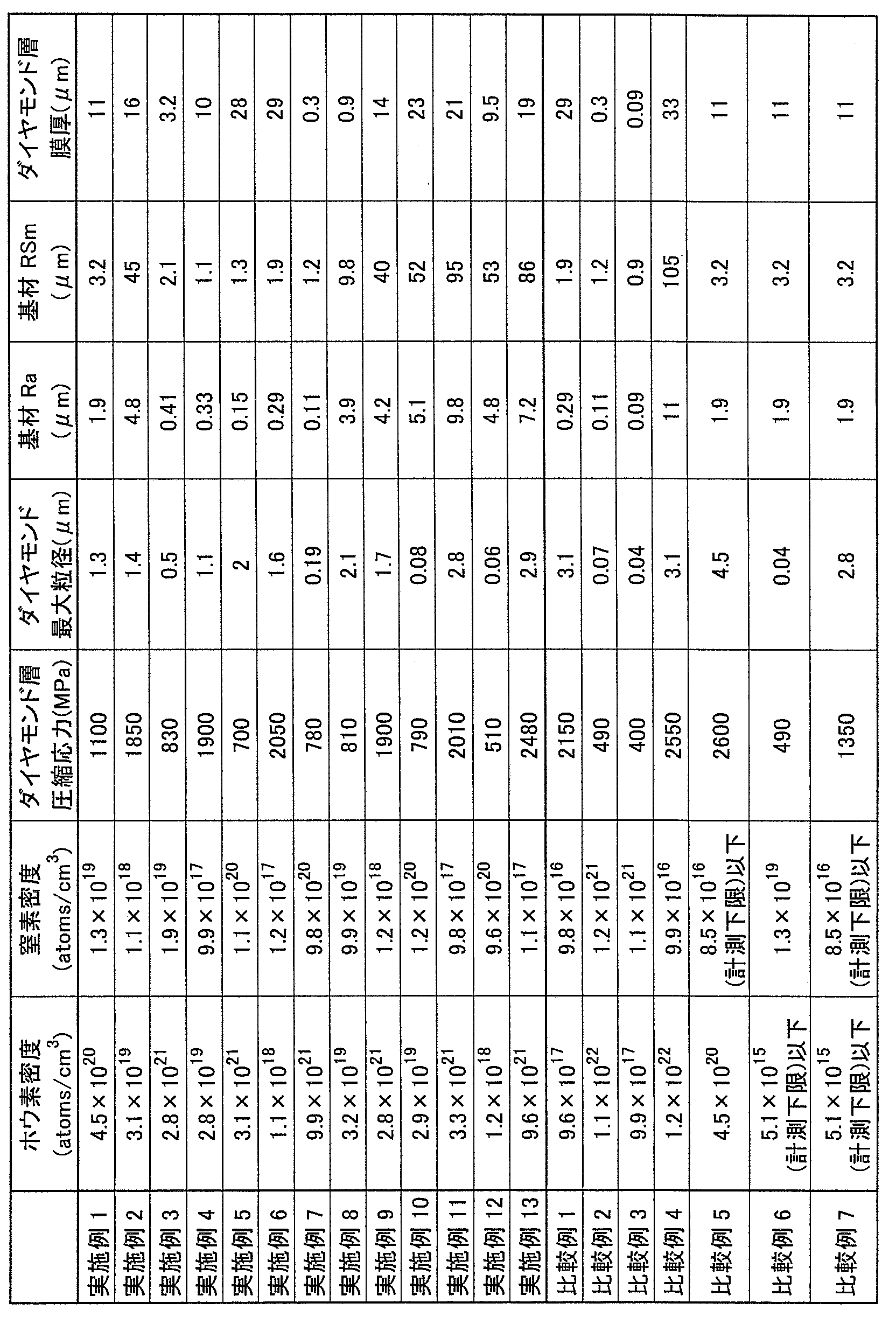
- polycrystalline diamond having a maximum particle size of 1.3 ⁇ m was coated on the substrate as a diamond layer by a scanning electron microscope (SEM), and the film thickness was 11 ⁇ m from cross-sectional observation. I found out that Elemental analysis of the diamond layer surface by SIMS confirmed that the diamond layer contained 4.5 ⁇ 10 20 atoms / cm 3 boron and 1.3 ⁇ 10 19 atoms / cm 3 nitrogen.
- the residual compressive stress on the surface of the diamond layer measured by the sin 2 ⁇ method using the (311) diffraction line of diamond was 1100 MPa.
- Table 1 shows the results obtained for Examples 2 to 13 and Comparative Examples 1 to 7 in the same manner as Example 1.
- “diamond layer compressive stress” indicates the residual compressive stress on the diamond layer surface
- “diamond maximum particle size” indicates the maximum particle size of diamond particles on the diamond layer surface
- “diamond layer film thickness” Indicates the diamond layer thickness.
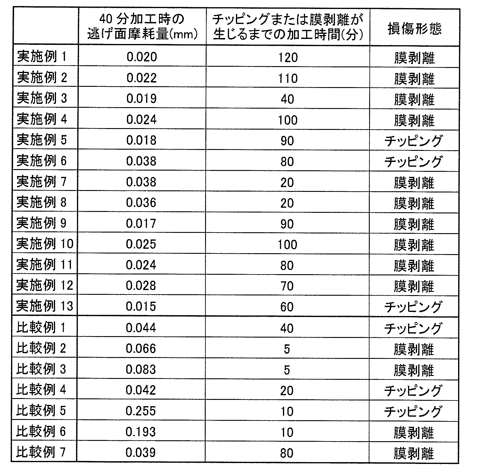
- each of the diamond-coated tools of Examples 1 to 13 and Comparative Examples 1 to 7 prepared above was subjected to wet intermittent cutting to evaluate the adhesion and chipping resistance of the diamond layer.
- Cutting conditions were as follows: a round bar made of ADC12 (12% Si-Al alloy) having 6 grooves in the axial direction as a work material, a cutting speed of 500 m / min, a cutting depth of 0.4 mm, and a feed of 0.1 mm. / Rev conditions.
- the damage pattern of the diamond layer was evaluated by evaluating the amount of flank wear during 40-minute processing and the processing time until chipping or film peeling (peeling of the diamond layer) occurred. The smaller the value of the flank wear amount and the longer the processing time until chipping or film peeling occurs, the longer the tool life is improved by improving the oxidation resistance and fracture resistance. The results are shown in Table 2.
Landscapes
- Chemical & Material Sciences (AREA)
- Engineering & Computer Science (AREA)
- Mechanical Engineering (AREA)
- Organic Chemistry (AREA)
- Chemical Kinetics & Catalysis (AREA)
- Materials Engineering (AREA)
- General Chemical & Material Sciences (AREA)
- Metallurgy (AREA)
- Inorganic Chemistry (AREA)
- Physics & Mathematics (AREA)
- Combustion & Propulsion (AREA)
- Plasma & Fusion (AREA)
- Cutting Tools, Boring Holders, And Turrets (AREA)
- Chemical Vapour Deposition (AREA)
- Drilling Tools (AREA)
- Crystals, And After-Treatments Of Crystals (AREA)
Description
<ダイヤモンド被覆工具>
本発明のダイヤモンド被覆工具は、基材と、該基材の表面を被覆したダイヤモンド層とを含む。これらの構成を有する限り、他の任意の構成を含んでいても差し支えない。なお、本発明において該基材の表面は、ダイヤモンド層により被覆されるものであるが、その表面の全面がダイヤモンド層で被覆される場合のみに限られるものではなく、その表面の一部がダイヤモンド層により被覆されていない場合も含まれる。
本発明のダイヤモンド層は、ダイヤモンドと1.0×10¹⁸~1.0×10²²atoms/cm3(1.0×1018atoms/cm3以上1.0×1022atoms/cm3以下、本願において数値をこのような範囲で示す場合は下限値および上限値を範囲内に含むものとする)のホウ素と1.0×1017~1.0×1021atoms/cm3の窒素とを含むことを特徴とする。
本発明のダイヤモンド被覆工具の基材としては、このような工具の基材として知られる従来公知のものを特に限定なく使用することができる。たとえば、超硬合金(たとえばWC基超硬合金、WCの他、Coを含み、あるいはさらにTi、Ta、Nb等の炭窒化物等を添加したものも含む)、サーメット(TiC、TiN、TiCN等を主成分とするもの)、高速度鋼、工具鋼、セラミックス(炭化チタン、炭化硅素、窒化硅素、窒化アルミニウム、酸化アルミニウム、およびこれらの混合体など)、立方晶型窒化硼素焼結体、ダイヤモンド焼結体等をこのような基材の例として挙げることができる。
本発明のダイヤモンド被覆工具の製造方法は、特に限定されるものではないが、たとえば基材上にダイヤモンド層を化学気相成長法により形成することにより製造することができる。
Claims (9)
- 基材と、該基材の表面を被覆したダイヤモンド層とを含み、
前記ダイヤモンド層は、ダイヤモンドと1.0×10¹⁸~1.0×10²²atoms/cm3のホウ素と1.0×1017~1.0×1021atoms/cm3の窒素とを含む、ダイヤモンド被覆工具。 - 前記ダイヤモンド層は、その表面における残留圧縮応力がX線応力測定において500~2500MPaである、請求項1に記載のダイヤモンド被覆工具。
- 前記ダイヤモンド層は、その表面におけるダイヤモンド粒子の最大粒径が0.05~3μmである、請求項1または2に記載のダイヤモンド被覆工具。
- 前記ダイヤモンド層は、3.0×10¹⁹~3.0×10²¹atoms/cm3のホウ素を含む、請求項1~3のいずれかに記載のダイヤモンド被覆工具。
- 前記ダイヤモンド層は、1.0×10¹⁸~1.0×10²⁰atoms/cm3の窒素を含む、請求項1~4のいずれかに記載のダイヤモンド被覆工具。
- 前記ダイヤモンド層は、その表面における残留圧縮応力がX線応力測定において800~2000MPaである、請求項1~5のいずれかに記載のダイヤモンド被覆工具。
- 前記基材は、超硬合金からなる、請求項1~6のいずれかに記載のダイヤモンド被覆工具。
- 前記基材は、その表面の算術平均粗さRaが0.1~10μmであり、かつ、粗さ曲線要素の平均長さRSmが1~100μmである、請求項1~7のいずれかに記載のダイヤモンド被覆工具。
- 前記ダイヤモンド層は、その膜厚が0.1~30μmである、請求項1~8のいずれかに記載のダイヤモンド被覆工具。
Priority Applications (3)
| Application Number | Priority Date | Filing Date | Title |
|---|---|---|---|
| CN201280066661.3A CN104053517A (zh) | 2012-01-10 | 2012-11-27 | 金刚石包覆工具 |
| EP12865072.8A EP2772330A4 (en) | 2012-01-10 | 2012-11-27 | DIAMOND COATED TOOL |
| US14/364,660 US20140341664A1 (en) | 2012-01-10 | 2012-11-27 | Diamond coated tool |
Applications Claiming Priority (2)
| Application Number | Priority Date | Filing Date | Title |
|---|---|---|---|
| JP2012-002149 | 2012-01-10 | ||
| JP2012002149 | 2012-01-10 |
Publications (1)
| Publication Number | Publication Date |
|---|---|
| WO2013105348A1 true WO2013105348A1 (ja) | 2013-07-18 |
Family
ID=48781312
Family Applications (1)
| Application Number | Title | Priority Date | Filing Date |
|---|---|---|---|
| PCT/JP2012/080582 Ceased WO2013105348A1 (ja) | 2012-01-10 | 2012-11-27 | ダイヤモンド被覆工具 |
Country Status (5)
| Country | Link |
|---|---|
| US (1) | US20140341664A1 (ja) |
| EP (1) | EP2772330A4 (ja) |
| JP (1) | JPWO2013105348A1 (ja) |
| CN (1) | CN104053517A (ja) |
| WO (1) | WO2013105348A1 (ja) |
Cited By (4)
| Publication number | Priority date | Publication date | Assignee | Title |
|---|---|---|---|---|
| EP3646975A1 (en) | 2018-10-31 | 2020-05-06 | Union Tool Co. | Drilling tool and method for manufacturing the same |
| WO2021075358A1 (ja) | 2019-10-18 | 2021-04-22 | 住友電工ハードメタル株式会社 | ダイヤモンド被覆工具 |
| EP3862117A1 (en) | 2020-02-07 | 2021-08-11 | Union Tool Co. | Cutting tool |
| KR20210101148A (ko) | 2020-02-07 | 2021-08-18 | 유니온쓰루 가부시키가이샤 | 절삭 공구 |
Families Citing this family (6)
| Publication number | Priority date | Publication date | Assignee | Title |
|---|---|---|---|---|
| CN103180073B (zh) * | 2010-10-27 | 2015-10-07 | 富士重工业株式会社 | 铣削加工用嵌件及铣削加工用刃尖更换式旋转切削刀具 |
| WO2016068231A1 (ja) * | 2014-10-29 | 2016-05-06 | 住友電気工業株式会社 | 複合ダイヤモンド体および複合ダイヤモンド工具 |
| TWI568670B (zh) * | 2015-10-30 | 2017-02-01 | 江信有限公司 | 具有高鑽石鍵結密度的複合鑽石材料 |
| EP3549911B1 (en) * | 2016-11-30 | 2022-06-01 | Sumitomo Electric Industries, Ltd. | Polycrystalline diamond and method for producing same, cutting tool, and processing method using polycrystalline diamond |
| US11292066B2 (en) | 2017-01-16 | 2022-04-05 | Osg Corporation | Tool having a boron doped diamond coating |
| US11739419B2 (en) * | 2017-04-27 | 2023-08-29 | INDIAN INSTITUTE OF TECHNOLOGY MADRAS (IIT Madras) | Highly adhesive CVD grown boron doped diamond graded layer on WC-Co |
Citations (5)
| Publication number | Priority date | Publication date | Assignee | Title |
|---|---|---|---|---|
| JPH03228504A (ja) * | 1989-06-15 | 1991-10-09 | Sumitomo Electric Ind Ltd | ダイヤモンド工具 |
| JPH0776775A (ja) * | 1993-09-10 | 1995-03-20 | Kobe Steel Ltd | ダイヤモンド被覆超硬合金工具 |
| JP2006150572A (ja) | 2004-12-01 | 2006-06-15 | Osg Corp | ボロンドープダイヤモンド被膜およびダイヤモンド被覆加工工具 |
| JP2009280421A (ja) | 2008-05-20 | 2009-12-03 | Sadao Takeuchi | 高強度ダイヤモンド膜工具 |
| JP2011038150A (ja) * | 2009-08-11 | 2011-02-24 | Sumitomo Electric Ind Ltd | ダイヤモンド被覆工具 |
Family Cites Families (9)
| Publication number | Priority date | Publication date | Assignee | Title |
|---|---|---|---|---|
| SE442305B (sv) * | 1984-06-27 | 1985-12-16 | Santrade Ltd | Forfarande for kemisk gasutfellning (cvd) for framstellning av en diamantbelagd sammansatt kropp samt anvendning av kroppen |
| GB9616043D0 (en) * | 1996-07-31 | 1996-09-11 | De Beers Ind Diamond | Diamond |
| JP4787387B2 (ja) * | 1998-07-22 | 2011-10-05 | 住友電工ハードメタル株式会社 | 耐クレータ性および強度に優れた切削工具とその製造方法 |
| JP3998871B2 (ja) * | 1999-07-28 | 2007-10-31 | 日本バイリーン株式会社 | 機能性粉体担持シート及び機能性粉体担持構造体 |
| BR0103109B1 (pt) * | 2001-06-08 | 2011-09-06 | ferramenta de corte e processo de formação desta. | |
| JP4985919B2 (ja) * | 2005-12-22 | 2012-07-25 | 三菱マテリアル株式会社 | 高硬度鋼の高速切削加工で優れた仕上げ面精度を長期にわたって発揮する表面被覆立方晶窒化ほう素基超高圧焼結材料製切削工具 |
| JP5005262B2 (ja) * | 2006-05-26 | 2012-08-22 | 三菱マテリアル株式会社 | 高硬度鋼の高速切削加工できわめて優れた仕上げ面精度を長期にわたって発揮する表面被覆立方晶窒化ほう素基超高圧焼結材料製切削工具 |
| TWI457475B (zh) * | 2008-05-05 | 2014-10-21 | Carnegie Inst Of Washington | 超韌性單晶型摻硼鑽石 |
| WO2010032137A1 (en) * | 2008-09-17 | 2010-03-25 | Diamond Innovations, Inc. | Cubic boron nitride ceramic composites and methods of making thereof |
-
2012
- 2012-11-27 US US14/364,660 patent/US20140341664A1/en not_active Abandoned
- 2012-11-27 JP JP2013553203A patent/JPWO2013105348A1/ja active Pending
- 2012-11-27 WO PCT/JP2012/080582 patent/WO2013105348A1/ja not_active Ceased
- 2012-11-27 CN CN201280066661.3A patent/CN104053517A/zh active Pending
- 2012-11-27 EP EP12865072.8A patent/EP2772330A4/en not_active Withdrawn
Patent Citations (5)
| Publication number | Priority date | Publication date | Assignee | Title |
|---|---|---|---|---|
| JPH03228504A (ja) * | 1989-06-15 | 1991-10-09 | Sumitomo Electric Ind Ltd | ダイヤモンド工具 |
| JPH0776775A (ja) * | 1993-09-10 | 1995-03-20 | Kobe Steel Ltd | ダイヤモンド被覆超硬合金工具 |
| JP2006150572A (ja) | 2004-12-01 | 2006-06-15 | Osg Corp | ボロンドープダイヤモンド被膜およびダイヤモンド被覆加工工具 |
| JP2009280421A (ja) | 2008-05-20 | 2009-12-03 | Sadao Takeuchi | 高強度ダイヤモンド膜工具 |
| JP2011038150A (ja) * | 2009-08-11 | 2011-02-24 | Sumitomo Electric Ind Ltd | ダイヤモンド被覆工具 |
Non-Patent Citations (1)
| Title |
|---|
| See also references of EP2772330A4 |
Cited By (6)
| Publication number | Priority date | Publication date | Assignee | Title |
|---|---|---|---|---|
| EP3646975A1 (en) | 2018-10-31 | 2020-05-06 | Union Tool Co. | Drilling tool and method for manufacturing the same |
| KR20200049539A (ko) | 2018-10-31 | 2020-05-08 | 유니온쓰루 가부시키가이샤 | 드릴링 공구 및 그 제조 방법 |
| WO2021075358A1 (ja) | 2019-10-18 | 2021-04-22 | 住友電工ハードメタル株式会社 | ダイヤモンド被覆工具 |
| US12257635B2 (en) | 2019-10-18 | 2025-03-25 | Sumitomo Electric Hardmetal Corp. | Diamond coated tool |
| EP3862117A1 (en) | 2020-02-07 | 2021-08-11 | Union Tool Co. | Cutting tool |
| KR20210101148A (ko) | 2020-02-07 | 2021-08-18 | 유니온쓰루 가부시키가이샤 | 절삭 공구 |
Also Published As
| Publication number | Publication date |
|---|---|
| JPWO2013105348A1 (ja) | 2015-05-11 |
| US20140341664A1 (en) | 2014-11-20 |
| CN104053517A (zh) | 2014-09-17 |
| EP2772330A1 (en) | 2014-09-03 |
| EP2772330A4 (en) | 2015-07-08 |
Similar Documents
| Publication | Publication Date | Title |
|---|---|---|
| WO2013105348A1 (ja) | ダイヤモンド被覆工具 | |
| EP3336218B1 (en) | Surface coated member | |
| KR102033188B1 (ko) | 경질 피복층이 우수한 내치핑성과 내마모성을 발휘하는 표면 피복 절삭 공구 | |
| JP5884138B2 (ja) | 表面被覆切削工具およびその製造方法 | |
| JP4690479B2 (ja) | ダイヤモンド被覆工具 | |
| JP5111379B2 (ja) | 切削工具及びその製造方法並びに切削方法 | |
| JP5768308B2 (ja) | 表面被覆切削工具 | |
| JP2009028894A (ja) | 被覆切削工具 | |
| WO2012063515A1 (ja) | 表面被覆切削工具 | |
| CN103108716B (zh) | 表面被覆切削工具 | |
| JP7649467B2 (ja) | 表面被覆切削工具 | |
| WO2015030073A1 (ja) | 被覆工具 | |
| WO2011052767A1 (ja) | 耐チッピング性にすぐれた表面被覆切削工具 | |
| US20210001409A1 (en) | Surface-coated cutting tool | |
| WO2018042740A1 (ja) | 硬質被覆層がすぐれた耐チッピング性、耐剥離性を発揮する表面被覆切削工具 | |
| WO2016158717A1 (ja) | 被覆切削工具 | |
| KR20180011148A (ko) | 경질 피복층이 우수한 내치핑성을 발휘하는 표면 피복 절삭 공구 | |
| JP7814093B2 (ja) | 耐欠損性にすぐれた表面被覆切削工具 | |
| JP7649468B2 (ja) | 表面被覆切削工具 | |
| CN111148589B (zh) | 硬质包覆层发挥优异的耐熔接性和耐异常损伤性的表面包覆切削工具 | |
| JP5569740B2 (ja) | 耐チッピング性にすぐれた表面被覆切削工具 | |
| WO2019065683A1 (ja) | 硬質被覆層がすぐれた耐溶着性と耐異常損傷性を発揮する表面被覆切削工具 | |
| JP2017024136A (ja) | 被覆切削工具 |
Legal Events
| Date | Code | Title | Description |
|---|---|---|---|
| 121 | Ep: the epo has been informed by wipo that ep was designated in this application |
Ref document number: 12865072 Country of ref document: EP Kind code of ref document: A1 |
|
| ENP | Entry into the national phase |
Ref document number: 2013553203 Country of ref document: JP Kind code of ref document: A |
|
| REEP | Request for entry into the european phase |
Ref document number: 2012865072 Country of ref document: EP |
|
| WWE | Wipo information: entry into national phase |
Ref document number: 2012865072 Country of ref document: EP |
|
| WWE | Wipo information: entry into national phase |
Ref document number: 14364660 Country of ref document: US |
|
| NENP | Non-entry into the national phase |
Ref country code: DE |