WO2013105509A1 - 生体試料測定装置 - Google Patents
生体試料測定装置 Download PDFInfo
- Publication number
- WO2013105509A1 WO2013105509A1 PCT/JP2013/000078 JP2013000078W WO2013105509A1 WO 2013105509 A1 WO2013105509 A1 WO 2013105509A1 JP 2013000078 W JP2013000078 W JP 2013000078W WO 2013105509 A1 WO2013105509 A1 WO 2013105509A1
- Authority
- WO
- WIPO (PCT)
- Prior art keywords
- measurement
- unit
- value
- check
- control unit
- Prior art date
- Legal status (The legal status is an assumption and is not a legal conclusion. Google has not performed a legal analysis and makes no representation as to the accuracy of the status listed.)
- Ceased
Links
Images


Classifications
-
- G—PHYSICS
- G01—MEASURING; TESTING
- G01N—INVESTIGATING OR ANALYSING MATERIALS BY DETERMINING THEIR CHEMICAL OR PHYSICAL PROPERTIES
- G01N27/00—Investigating or analysing materials by the use of electric, electrochemical, or magnetic means
- G01N27/26—Investigating or analysing materials by the use of electric, electrochemical, or magnetic means by investigating electrochemical variables; by using electrolysis or electrophoresis
- G01N27/416—Systems
- G01N27/4163—Systems checking the operation of, or calibrating, the measuring apparatus
-
- G—PHYSICS
- G01—MEASURING; TESTING
- G01N—INVESTIGATING OR ANALYSING MATERIALS BY DETERMINING THEIR CHEMICAL OR PHYSICAL PROPERTIES
- G01N33/00—Investigating or analysing materials by specific methods not covered by groups G01N1/00 - G01N31/00
- G01N33/48—Biological material, e.g. blood, urine; Haemocytometers
- G01N33/483—Physical analysis of biological material
- G01N33/487—Physical analysis of biological material of liquid biological material
- G01N33/4875—Details of handling test elements, e.g. dispensing or storage, not specific to a particular test method
- G01N33/48771—Coding of information, e.g. calibration data, lot number
-
- G—PHYSICS
- G01—MEASURING; TESTING
- G01N—INVESTIGATING OR ANALYSING MATERIALS BY DETERMINING THEIR CHEMICAL OR PHYSICAL PROPERTIES
- G01N33/00—Investigating or analysing materials by specific methods not covered by groups G01N1/00 - G01N31/00
- G01N33/48—Biological material, e.g. blood, urine; Haemocytometers
- G01N33/50—Chemical analysis of biological material, e.g. blood, urine; Testing involving biospecific ligand binding methods; Immunological testing
- G01N33/66—Chemical analysis of biological material, e.g. blood, urine; Testing involving biospecific ligand binding methods; Immunological testing involving blood sugars, e.g. galactose
Definitions
- the present invention relates to a biological sample measuring apparatus that measures biological information such as blood glucose level from blood.
- the configuration of a conventional biological sample measuring device includes a main body case having a sensor mounting portion, a measuring portion connected to the sensor mounting portion, a control portion connected to the measuring portion, and a storage portion connected to the control portion. And had.
- the conventional biological sample measuring apparatus is not easy to use in the following points.
- a dedicated management chip must be mounted on the sensor mounting portion in advance to determine whether there is an abnormality in the biological sample measurement device, which is inconvenient.
- the biological sample measuring device of the present invention includes a main body case having a sensor mounting portion, a measuring portion connected to the sensor mounting portion, a control portion connected to the measuring portion, and a storage portion connected to the control portion.
- the measurement unit connects its input side to a switch unit that switches to any one of connection to the sensor mounting unit, connection to the reference resistor, and open state.
- the control unit has a measurement preparation mode and a measurement mode. In the measurement preparation mode, the following (Check 01) and (Check 02) are performed to determine whether there is an abnormality in the measurement unit.
- the switch unit connects the input side of the measurement unit to a reference resistor to obtain a first measurement value, and whether or not the first measurement value is within the first reference range stored in the storage unit. Determine whether.
- the switch unit sets the input side of the measurement unit to an open state, obtains the second measurement value, and determines whether the second measurement value is within the second reference range stored in the storage unit To do.
- the control unit performs measurement in two states, that is, a state in which the input side of the measurement unit is connected to the reference resistor and an open state. Find the value. Then, it is determined that the two measurement values are within the reference range set at the time of manufacture, and it is confirmed that the current measurement unit maintains the characteristics at the time of manufacture, that is, there is no abnormality.
- the present invention provides an easy-to-use biological sample measuring device can do.
- FIG. 1 is a perspective view showing a method for using the biological sample measuring apparatus according to the first embodiment of the present invention.
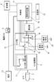
- FIG. 2 is a control block diagram of the biological sample measurement device according to the first and second embodiments of the present invention.
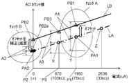
- FIG. 3 is a characteristic diagram of measured values of the biological sample measuring device according to the first and second embodiments of the present invention.
- FIG. 4 is an operation flowchart of the biological sample measuring apparatus according to the first embodiment of the present invention.
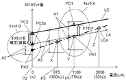
- FIG. 5 is a characteristic diagram of measured values of the biological sample measuring device according to the first embodiment of the present invention.
- a main body case 1 of a measuring instrument which is an example of a biological sample measuring device that measures a blood glucose level from blood is formed in a substantially rectangular shape.
- a sensor mounting portion 4 for inserting a connection terminal 3 of a blood glucose level sensor 2 as an example of a sensor is provided on the distal end side of the main body case 1.
- a power button 5 for turning on and off the measuring instrument, a display unit 6 for displaying measurement results, and a discharge lever 7 for removing the blood glucose level sensor 2 from the main body case 1 are provided on the upper surface of the main body case 1.
- the blood glucose level sensor 2 is attached to the sensor mounting portion 4 and blood is spotted on the spotting portion 8 on the distal end side of the blood glucose level sensor 2 in that state, the blood glucose level at that time is 2 is measured by the second measuring unit 9 and displayed on the display unit 6.
- FIG. 2 is an electrical control block diagram of the measuring instrument.
- the sensor mounting unit 4 is connected to the measuring unit 9 via the switch unit 10, and the measuring unit 9 is connected to the control unit 11.
- the control unit 11 is connected to a storage unit 12.
- the storage unit 12 stores a reference value PA1 and a reference value PA2 and a threshold value A1 of the reference value PA1 and a threshold value A2 of the reference value PA2 at the time of manufacture shown in FIG.
- a display unit 6 is connected to the control unit 11, and a battery 13 is connected via the power button 5.
- the sensor mounting part 4 is connected to the input side of the measuring part 9 via a switch 14, and one side of a reference resistor 16 is connected via a switch 15. The other side of the reference resistor 16 is connected to the ground.
- the switch 14 and the switch 15 constitute the switch unit 10 of the present embodiment, and are connected to the control unit 11, and the control unit 11 controls on / off.
- the control unit 11 includes a measurement preparation mode for preparing for measurement and a measurement mode for measuring blood glucose level.
- a sensor insertion detection unit 17 is provided in the sensor mounting unit 4 and connected to the control unit 11.
- control unit 11 performs measurement for determination at two locations, and obtains a characteristic line LB (shown in FIG. 3) indicating the measurement characteristics of the measurement unit 9 from the measurement values at the two locations. Then, the difference between the deviation and the inclination of the current characteristic line LB and the characteristic line LA at the time of manufacture (shown in FIG. 3) is determined at two places where measurement was performed for determination.
- a characteristic line LB shown in FIG. 3
- the determination at these two locations confirms that the current measurement unit 9 maintains the characteristics at the time of manufacture, that is, the measurement unit 9 has no abnormality.
- the measurer presses the power button 5 to turn on the power of the measuring instrument (step S1 in FIG. 4), and attaches the connection terminal 3 of the blood glucose level sensor 2 to the sensor mounting part 4. Then, the sensor insertion detection part 17 detects insertion of the blood glucose level sensor 2, and notifies the control part 11 (step S2 of FIG. 4).
- the power supply of the measuring device may be controlled by turning on the power of the measuring device when the sensor insertion detecting unit 17 detects the insertion of the blood glucose level sensor 2.
- the control unit 11 enters the measurement preparation mode and starts determining whether the measurement unit 9 is abnormal. The determination of the presence / absence of abnormality will be described with reference to FIG.
- the blood glucose level is measured by causing blood and a reagent (not shown) to react in the spotting part 8 of the blood glucose level sensor 2, and this reaction current is converted into a current-voltage circuit (not shown). )), And this voltage is converted into a digital AD count value by an AD conversion circuit (not shown). Then, a blood glucose level is calculated by obtaining a current value (a source value for calculating the blood glucose level) corresponding to the AD count value.
- the AD count value is on the vertical axis
- the current value (the value from which the blood glucose level is calculated) is on the horizontal axis.
- the measuring device is measured with three resistors of 100 k ⁇ , 75 k ⁇ , and 33 k ⁇ , for example, instead of the blood glucose level sensor 2, and each value (AD count value, specifically, a white circle in FIG. 3). Further, the AD count values X, Y, and Z are determined. An approximate straight line obtained from the values of these three points (AD count values X, Y, Z) is taken as a characteristic line LA (indicated by a one-dot chain line in FIG. 3) of the measurement unit 9 at the time of manufacture.
- 75 k ⁇ is a value corresponding to a standard blood glucose level (for example, 90 mg / dL) when a healthy person is measured using the blood glucose level sensor of the present embodiment.
- the measuring device converts the AD count value into a current value using the characteristic line LA of the measuring unit 9, and the control unit 11 performs correction such as temperature correction to calculate the blood sugar level.
- measurement for determination is performed at two points of reference point P1 (75 k ⁇ ) and reference point P2 ( ⁇ , that is, the input side of measurement unit 9 is open). And the presence or absence of abnormality of the measurement part 9 is determined with these two reference points P1 and P2.
- the data to be stored may not be the measured values of the reference value PA1 and the reference value PA2, but may be other numerical values that can be obtained by calculation.
- the reference point P1 is determined by check A, and the reference point P2 is determined by check B.
- check A it is determined how much the current characteristic of the measuring section 9 is offset from the characteristic line LA at the time of manufacture (how much it is shifted) at the reference point P1 (75 k ⁇ ).
- control unit 11 turns off the switch 14 of the switch unit 10 and turns on the switch 15 to connect the input side of the measurement unit 9 to the reference resistor 16 (75 k ⁇ ). Is measured to obtain a measured value PB1 (AD count value) (step S3 in FIG. 4).
- the measurement value PB1 is the same value as the reference value PA1, but, for example, the AD converter circuit (not shown) of the measurement unit 9 has an external influence such as a temperature drift due to the temperature of the measurement state.
- the value may be offset from the reference value PA1 at the time of manufacture.
- the abnormality determination unit 18 of the control unit 11 determines whether or not the measurement value PB1 is in the normal range (first reference range) defined by the size of the threshold value A1 above and below the reference value PA1. (Step S4 in FIG. 4).
- the current characteristic of the measurement unit 9 is different from the characteristic at the time of manufacture, and normal measurement cannot be performed. I contacted the store. 0120-01-0123> is displayed to inform the measurer that the measuring instrument has failed, and to contact the dealer or customer service (step S5 in FIG. 4).
- control unit 11 stores predetermined error information (for example, error content, occurrence date and time) in the storage unit 12 (step S6 in FIG. 4), and ends the process without shifting to the measurement mode (in FIG. 4). Step S7).
- predetermined error information for example, error content, occurrence date and time
- control unit 11 calculates an offset value by subtracting the reference value PA1 from the measured value PB1, and temporarily stores the offset value in the storage unit 12 (FIG. 4). Step S8).
- the switch unit 10 connects the input side of the measurement unit 9 to the reference resistor 16 to obtain the first measurement value PB1, and the first measurement value PB1 is stored in the storage unit 12. It is determined whether it is within the reference range of 1.
- check B is performed.
- this check B it is determined whether or not the slope indicating the characteristics of the measurement section 9 is the same as the slope of the characteristic line LA at the time of manufacture at the reference point P2 ( ⁇ , that is, the input side of the measurement section 9 is open). .
- control unit 11 turns off the switch 14 of the switch unit 10 and turns off the switch 15 so that the input side of the measurement unit 9 is in an open state, and the measurement unit 9 measures this open state and measures the measured value PB2. (AD count value) is obtained (step S9 in FIG. 4).
- a line connecting the measured value PB1 obtained by measuring the reference resistance 16 and the measured value PB2 becomes a characteristic line LB representing the current characteristic of the measuring unit 9.
- control unit 11 corrects (subtracts) the measurement value PB2 with the offset value obtained by the check A temporarily stored in the storage unit 12 to obtain the measurement value PB2a (FIG. 4). Step S10).
- the abnormality determination unit 18 of the control unit 11 determines whether or not the corrected measurement value PB2a is within the normal range (second reference range) defined by the magnitude of the threshold value A2 above and below the reference value PA2. (Step S11 in FIG. 4).
- the measured value PB2a is in the normal range, as shown in FIG. 3, when the current characteristic line LB is corrected (subtracted) by the offset value, it matches the characteristic line LA at the time of manufacture or falls within the normal range. . That is, in this state, the slope of the characteristic line LB is the same as or substantially the same as the slope of the characteristic line LA at the time of manufacture, and the current measuring unit 9 is offset from the characteristics at the time of manufacture. Maintains the characteristics of manufacturing. That is, there is no abnormality in the current measurement unit 9, and the control unit 11 determines that the blood glucose level can be measured.
- the switch unit 10 opens the input side of the measurement unit 9 to obtain the second measurement value PB2a, and the second measurement value PB2a is stored in the storage unit 12. It is determined whether it is within the range.
- the control unit 11 performs steps S5 to S6 in FIG. 4 and ends the processing without shifting to the measurement mode (step S7 in FIG. 4).
- step S11 in FIG. 4 when the measured value PB2a is within the normal range, the check B ends normally (step S11 in FIG. 4), and another error check before measurement (error check performed in the prior art, for example, environment After performing the temperature check, the hardware operation check, and the storage unit 12 check (step S12 in FIG. 4), the control unit 11 switches to the measurement mode. If an error occurs in step S12 in FIG. 4, the processing in steps S5 to S7 in FIG. 4 is performed, and the measurement ends.
- control unit 11 turns on the switch 14 of the switch unit 10 and turns off the switch 15, connects the input side of the measurement unit 9 to the sensor mounting unit 4, and displays “Ready for measurement” on the display unit 6. "Please apply blood to the sensor” is displayed.
- blood is spotted on the blood glucose level sensor 2, normal blood glucose level measurement is performed (step S13 in FIG. 4).
- control unit 11 displays the measured blood glucose level on the display unit 6 (step S14 in FIG. 4), stores the blood glucose level in the storage unit 12 (step S15 in FIG. 4), and ends the measurement. (Step S7 in FIG. 4).
- an AD conversion circuit (not shown) of the measuring unit 9 causes the impact of dropping the measuring instrument or the deterioration of parts due to aging.
- the measurement unit 9 is affected by external influence factors such as.
- the measurement value PC1 of the check A (resistance is 75 k ⁇ ) is in the normal range defined by the threshold A1
- the measurement value PC2a of the check B (the measurement value PC2 in the open state is
- the values corrected in steps S8 to S10 in FIG. 4 may be out of the normal range defined by the threshold A2 with respect to the reference value PA2.
- the characteristic line LC connecting the measured value PC1 of check A and the measured value PC2 of check B is different from the slope of the characteristic line LA at the time of manufacture.
- the characteristic line LC is corrected with an offset value.
- the characteristic line LCa no longer coincides with the characteristic line LA at the time of manufacture. For this reason, even if the blood glucose level sensor 2 is attached and the blood glucose level is measured, a correct blood glucose level cannot be obtained.
- control unit 11 determines that the current measurement unit 9 does not maintain the characteristics at the time of manufacture, performs the error processing of steps S5 to S6 in FIG. 4, and stops the subsequent blood glucose level measurement. (Step S7 in FIG. 4).
- the control unit 11 confirms that the current measurement unit 9 maintains the characteristics at the time of manufacture, that is, the measurement unit 9 has no abnormality.
- the reference point P1 75 k ⁇ , that is, the reference resistor 16
- the reference point P2 ⁇ , that is, the input of the measuring unit 9 are determined as described above in order to determine whether the measuring instrument is abnormal. Measurement and confirmation are performed at two places (a plurality of places) with the side open.
- one of the measurement points is measured and confirmed in an open state like the reference point P2 ( ⁇ ). For this reason, it is possible to perform measurement and confirmation at two locations with a configuration in which one reference resistor is provided, and it is possible to determine whether there is an abnormality in the measuring instrument with a simple configuration.
- the normal range (second reference range) defined by the threshold value A2 of check B is set smaller than the normal range (first reference range) defined by the threshold value A1 of check A. . For this reason, operation
- the measurement value of the measurement unit 9 is temporarily offset as described above. As described above, it can be corrected by obtaining the offset value. For this reason, in the check A, the normal range defined by the threshold A1 is set large. Thereby, it is possible to deal with a wider range of external influence factors such as temperature drift.
- the normal range defined by the threshold A2 is set small.
- the inclination of the characteristic line LC is strictly compared with the inclination of the characteristic line LA at the time of manufacture. That is, as described above, in the measurement unit 9, when the slope of the current characteristic line LC is different from the slope of the characteristic line LA at the time of manufacture, an accurate blood glucose level can no longer be obtained. This inclination is determined strictly.
- the reference point P1 75 k ⁇ , that is, the reference resistor 16
- the reference point P2 ⁇ , that is, the measurement unit 9 are determined as described above in order to determine whether the measuring instrument is abnormal or not. Measurement and confirmation are performed at two locations in a state where the input side is open), and it is confirmed that there is no abnormality in the measurement unit 9. That is, measurement and confirmation are performed at two places (a plurality of places).
- one side of a reference resistor 20 (a resistance corresponding to the reference point P3 is 100 k ⁇ ) is connected to the input side of the measurement unit 9 via a switch 19, and the reference resistor 20 Connect the other side of to the ground.
- the switch 19 together with the switch 14 and the switch 15 constitutes the switch unit 10 and is connected to the control unit 11.
- the switches 14, 15, and 19 are individually controlled by the control unit 11.
- the storage unit 12 stores a threshold value A3 shown in FIGS. 3 and 5 as a normal range (third reference range) of the measured value of the reference resistance 20 (100 k ⁇ ).
- control unit 11 uses the switch unit 10 to connect the input side of the measurement unit 9 to the sensor mounting unit 4, to the reference resistor 16 (75 k ⁇ ), and to the reference resistor 20 (100 k ⁇ ). It can be switched to either.
- measurement and confirmation can be performed at the reference point P1 and the reference point P3, and the presence / absence of abnormality of the measuring instrument can be determined.
- the switch unit 10 connects the input side of the measurement unit 9 to the first reference resistor 16 to obtain the first measurement value PB1, and the first measurement value PB1 is stored in the storage unit 12. It is determined whether it is within the set first reference range.
- the switch unit 10 connects the input side of the measurement unit 9 to the second reference resistor 20 to obtain the third measurement value PB3, and the third measurement value PB3 is stored in the storage unit 12. It is determined whether it is within the set third reference range.
- the present invention is expected to be widely used as a biological sample measuring device for measuring biological information such as blood glucose level from blood.
Landscapes
- Health & Medical Sciences (AREA)
- Life Sciences & Earth Sciences (AREA)
- Engineering & Computer Science (AREA)
- Biomedical Technology (AREA)
- Chemical & Material Sciences (AREA)
- Physics & Mathematics (AREA)
- Immunology (AREA)
- Hematology (AREA)
- Molecular Biology (AREA)
- Urology & Nephrology (AREA)
- General Health & Medical Sciences (AREA)
- General Physics & Mathematics (AREA)
- Pathology (AREA)
- Analytical Chemistry (AREA)
- Biochemistry (AREA)
- Medicinal Chemistry (AREA)
- Food Science & Technology (AREA)
- Biophysics (AREA)
- Optics & Photonics (AREA)
- Chemical Kinetics & Catalysis (AREA)
- Electrochemistry (AREA)
- Diabetes (AREA)
- Biotechnology (AREA)
- Cell Biology (AREA)
- Microbiology (AREA)
- Investigating Or Analyzing Materials By The Use Of Electric Means (AREA)
- Investigating Or Analysing Biological Materials (AREA)
Abstract
Description
以下、本発明の第1の実施の形態における生体試料測定装置について、図面を用いて説明する。
本発明の第1の実施の形態においては、測定器の異常有無を判定するために、上述のごとく、基準点P1(75kΩ、つまり基準抵抗16)、基準点P2(∞Ω、つまり測定部9の入力側がオープンな状態)の2箇所で測定および確認を行い、測定部9に異常がないことを確認する。すなわち、2箇所(複数箇所)で測定および確認を行うことを特徴とするものである。
2 血糖値センサ(センサの一例)
3 接続端子
4 センサ装着部
5 電源ボタン
6 表示部
7 排出レバー
8 点着部
9 測定部
10 スイッチ部
11 制御部
12 記憶部
13 電池
14 スイッチ
15 スイッチ
16 基準抵抗
17 センサ挿入検知部
18 異常判定部
19 スイッチ
20 基準抵抗
A1,A2,A3 閾値
LA,LB,LC,LCa 特性線
P1,P2,P3 基準点
PA1,PA2 基準値
PB1,PB2,PB2a,PB3 測定値
PC1,PC2,PC2a 測定値
Claims (4)
- センサ装着部を有する本体ケースと、前記センサ装着部に接続された測定部と、この測定部に接続された制御部と、この制御部に接続された記憶部と、を備え、
前記測定部は、その入力側を、前記センサ装着部への接続、第1の基準抵抗への接続、オープン状態、のいずれかに切り換えるスイッチ部に接続し、前記制御部は、測定準備モードと測定モードを有するとともに、測定準備モードでは、次の(チェック01)、(チェック02)を実施して前記測定部の異常の有無を判定する構成とした生体試料測定装置。
(チェック01)前記スイッチ部により前記測定部の入力側を前記第1の基準抵抗へ接続して第1の測定値を求め、この第1の測定値が前記記憶部に記憶された第1の基準範囲内であるか否かを判定する。
(チェック02)前記スイッチ部により前記測定部の入力側をオープン状態として第2の測定値を求め、この第2の測定値が前記記憶部に記憶された第2の基準範囲内であるか否かを判定する。 - 前記制御部は、前記(チェック01)の判定を実施した後、前記第1の判定値と前記第1の基準範囲内の基準値とからオフセット値を求め、前記(チェック02)の判定において、前記オフセット値で補正した前記第2の測定値が第2の基準範囲内であるか否かを判定する請求項1に記載の生体試料測定装置。
- 前記第2の基準範囲は、前記第1の基準範囲よりも小さくした請求項1または2のいずれか一項に記載の生体試料測定装置。
- センサ装着部を有する本体ケースと、前記センサ装着部に接続された測定部と、この測定部に接続された制御部と、この制御部に接続された記憶部と、を備え、前記測定部は、その入力側を、前記センサ装着部への接続、前記第1の基準抵抗への接続、第2の基準抵抗への接続、のいずれかに切り換えるスイッチ部に接続し、
前記制御部は、測定準備モードと測定モードを有するとともに、測定準備モードでは、次の(チェック03)、(チェック04)を実施して前記測定部の異常の有無を判定する構成とした生体試料測定装置。
(チェック03)前記スイッチ部により前記測定部の入力側を前記第1の基準抵抗へ接続して第1の測定値を求め、この第1の測定値が前記記憶部に記憶された第1の基準範囲内であるか否かを判定する。
(チェック04)前記スイッチ部により前記測定部の入力側を前記第2の基準抵抗に接続して第3の測定値を求め、この第3の測定値が前記記憶部に記憶された第3の基準範囲内であるか否かを判定する。
Priority Applications (3)
| Application Number | Priority Date | Filing Date | Title |
|---|---|---|---|
| EP13735998.0A EP2803986B1 (en) | 2012-01-13 | 2013-01-11 | Biological sample measurement apparatus |
| US14/370,215 US9581566B2 (en) | 2012-01-13 | 2013-01-11 | Biological sample measurement device |
| JP2013553270A JP5889920B2 (ja) | 2012-01-13 | 2013-01-11 | 生体試料測定装置 |
Applications Claiming Priority (4)
| Application Number | Priority Date | Filing Date | Title |
|---|---|---|---|
| JP2012005001 | 2012-01-13 | ||
| JP2012-005001 | 2012-01-13 | ||
| JP2012243345 | 2012-11-05 | ||
| JP2012-243345 | 2012-11-05 |
Publications (1)
| Publication Number | Publication Date |
|---|---|
| WO2013105509A1 true WO2013105509A1 (ja) | 2013-07-18 |
Family
ID=48781458
Family Applications (1)
| Application Number | Title | Priority Date | Filing Date |
|---|---|---|---|
| PCT/JP2013/000078 Ceased WO2013105509A1 (ja) | 2012-01-13 | 2013-01-11 | 生体試料測定装置 |
Country Status (4)
| Country | Link |
|---|---|
| US (1) | US9581566B2 (ja) |
| EP (1) | EP2803986B1 (ja) |
| JP (1) | JP5889920B2 (ja) |
| WO (1) | WO2013105509A1 (ja) |
Cited By (1)
| Publication number | Priority date | Publication date | Assignee | Title |
|---|---|---|---|---|
| JP2016003975A (ja) * | 2014-06-18 | 2016-01-12 | 沖電気工業株式会社 | 信号処理装置、信号処理方法及びプログラム |
Citations (5)
| Publication number | Priority date | Publication date | Assignee | Title |
|---|---|---|---|---|
| JP2003515122A (ja) | 1999-11-17 | 2003-04-22 | フェムトメトリクス,インコーポレイテッド | 化学物質を収集および検出するための装置および方法 |
| JP2010008121A (ja) * | 2008-06-25 | 2010-01-14 | Denso Corp | センサ出力処理装置及びセンサ出力処理システム |
| JP2010230525A (ja) * | 2009-03-27 | 2010-10-14 | Gunze Ltd | バイオセンサが取り付けられる計測表示装置 |
| JP2011027756A (ja) * | 2004-04-16 | 2011-02-10 | Denso Corp | ガス濃度検出装置 |
| JP2011143988A (ja) * | 2010-01-13 | 2011-07-28 | Toshiba Elevator Co Ltd | エレベータ案内装置 |
Family Cites Families (5)
| Publication number | Priority date | Publication date | Assignee | Title |
|---|---|---|---|---|
| ES2153335T3 (es) | 1993-06-08 | 2006-09-01 | Roche Diagnostics Operations, Inc. | Medidor biosensor que detecta el ajuste apropiado de los electrodos y distingue tiras de muestra y tiras de comprobacion. |
| FR2710413B1 (fr) | 1993-09-21 | 1995-11-03 | Asulab Sa | Dispositif de mesure pour capteurs amovibles. |
| JP3905764B2 (ja) | 2002-01-24 | 2007-04-18 | 株式会社東芝 | 小型検査機器及び精度管理チップ |
| US7776194B2 (en) | 2004-04-16 | 2010-08-17 | Denso Corporation | Gas concentration measuring apparatus designed to compensate for output error |
| US7556723B2 (en) | 2004-06-18 | 2009-07-07 | Roche Diagnostics Operations, Inc. | Electrode design for biosensor |
-
2013
- 2013-01-11 WO PCT/JP2013/000078 patent/WO2013105509A1/ja not_active Ceased
- 2013-01-11 JP JP2013553270A patent/JP5889920B2/ja active Active
- 2013-01-11 US US14/370,215 patent/US9581566B2/en active Active
- 2013-01-11 EP EP13735998.0A patent/EP2803986B1/en active Active
Patent Citations (5)
| Publication number | Priority date | Publication date | Assignee | Title |
|---|---|---|---|---|
| JP2003515122A (ja) | 1999-11-17 | 2003-04-22 | フェムトメトリクス,インコーポレイテッド | 化学物質を収集および検出するための装置および方法 |
| JP2011027756A (ja) * | 2004-04-16 | 2011-02-10 | Denso Corp | ガス濃度検出装置 |
| JP2010008121A (ja) * | 2008-06-25 | 2010-01-14 | Denso Corp | センサ出力処理装置及びセンサ出力処理システム |
| JP2010230525A (ja) * | 2009-03-27 | 2010-10-14 | Gunze Ltd | バイオセンサが取り付けられる計測表示装置 |
| JP2011143988A (ja) * | 2010-01-13 | 2011-07-28 | Toshiba Elevator Co Ltd | エレベータ案内装置 |
Non-Patent Citations (1)
| Title |
|---|
| See also references of EP2803986A4 |
Cited By (1)
| Publication number | Priority date | Publication date | Assignee | Title |
|---|---|---|---|---|
| JP2016003975A (ja) * | 2014-06-18 | 2016-01-12 | 沖電気工業株式会社 | 信号処理装置、信号処理方法及びプログラム |
Also Published As
| Publication number | Publication date |
|---|---|
| JP5889920B2 (ja) | 2016-03-22 |
| EP2803986A4 (en) | 2015-05-27 |
| US20140379274A1 (en) | 2014-12-25 |
| EP2803986B1 (en) | 2018-02-14 |
| JPWO2013105509A1 (ja) | 2015-05-11 |
| EP2803986A1 (en) | 2014-11-19 |
| US9581566B2 (en) | 2017-02-28 |
Similar Documents
| Publication | Publication Date | Title |
|---|---|---|
| US20160334357A1 (en) | Liquid sample measuring method, and measuring device | |
| US20070119267A1 (en) | Electronic torque wrench with a torque compensation device | |
| US20080136378A1 (en) | Method and apparatus for detecting battery state of charge | |
| US9316649B2 (en) | Biological sample measuring device and method for measuring biological sample using same | |
| US6356086B1 (en) | Method and apparatus for the in-circuit testing of a capacitor | |
| US9795317B2 (en) | Body composition measurement device, body composition measurement method, and correction method in body composition measurement | |
| CN102346242A (zh) | 电导率测量系统的校准 | |
| WO2023168542A1 (zh) | 电池连接件的接触电阻的标定方法、装置及用电装置 | |
| CN112731241B (zh) | 晶圆测试机台的校准工具和校准方法 | |
| US20020178808A1 (en) | Point level device with automatic threshold setting | |
| KR101022838B1 (ko) | 오토코딩용 저항전극을 구비한 센서 스트립을 채용하는 혈당측정장치 | |
| JP5889920B2 (ja) | 生体試料測定装置 | |
| US20200378851A1 (en) | Method and system for determining reliability of a pressure sensor | |
| TWI396842B (zh) | 生物感測測定機、生物感測測定系統及生物感測測定方法 | |
| EP2661617B1 (en) | Glucose measurement using a current source | |
| TW200600802A (en) | Method for correcting measurement error and instrument for measuring characteristics of electronic component | |
| US7794655B2 (en) | Test fluid measurement device and sensitivity calibration method thereof | |
| TWI516786B (zh) | Detection and debugging of the system | |
| JP7598659B2 (ja) | 計測装置 | |
| US12392836B2 (en) | Battery sensor | |
| JP2018132394A (ja) | pH計 | |
| US20170188915A1 (en) | Measurement error correction device of bio-measurer | |
| KR101084895B1 (ko) | 이차 전지 내부 저항 및 무부하 전위 검사 설비의 자체회로저항 보정 장치 | |
| JP2007285913A (ja) | 穀物水分測定装置 | |
| CN115183899B (zh) | 一种体温检测方法、装置、介质及体温检测仪 |
Legal Events
| Date | Code | Title | Description |
|---|---|---|---|
| 121 | Ep: the epo has been informed by wipo that ep was designated in this application |
Ref document number: 13735998 Country of ref document: EP Kind code of ref document: A1 |
|
| ENP | Entry into the national phase |
Ref document number: 2013553270 Country of ref document: JP Kind code of ref document: A |
|
| WWE | Wipo information: entry into national phase |
Ref document number: 14370215 Country of ref document: US |
|
| WWE | Wipo information: entry into national phase |
Ref document number: 2013735998 Country of ref document: EP |
|
| NENP | Non-entry into the national phase |
Ref country code: DE |