WO2013105590A1 - 燃料電池システム - Google Patents
燃料電池システム Download PDFInfo
- Publication number
- WO2013105590A1 WO2013105590A1 PCT/JP2013/050261 JP2013050261W WO2013105590A1 WO 2013105590 A1 WO2013105590 A1 WO 2013105590A1 JP 2013050261 W JP2013050261 W JP 2013050261W WO 2013105590 A1 WO2013105590 A1 WO 2013105590A1
- Authority
- WO
- WIPO (PCT)
- Prior art keywords
- cathode
- fuel cell
- flow rate
- internal resistance
- cathode gas
- Prior art date
- Legal status (The legal status is an assumption and is not a legal conclusion. Google has not performed a legal analysis and makes no representation as to the accuracy of the status listed.)
- Ceased
Links
Images







Classifications
-
- H—ELECTRICITY
- H01—ELECTRIC ELEMENTS
- H01M—PROCESSES OR MEANS, e.g. BATTERIES, FOR THE DIRECT CONVERSION OF CHEMICAL ENERGY INTO ELECTRICAL ENERGY
- H01M8/00—Fuel cells; Manufacture thereof
- H01M8/04—Auxiliary arrangements, e.g. for control of pressure or for circulation of fluids
- H01M8/04082—Arrangements for control of reactant parameters, e.g. pressure or concentration
- H01M8/04089—Arrangements for control of reactant parameters, e.g. pressure or concentration of gaseous reactants
-
- H—ELECTRICITY
- H01—ELECTRIC ELEMENTS
- H01M—PROCESSES OR MEANS, e.g. BATTERIES, FOR THE DIRECT CONVERSION OF CHEMICAL ENERGY INTO ELECTRICAL ENERGY
- H01M8/00—Fuel cells; Manufacture thereof
- H01M8/04—Auxiliary arrangements, e.g. for control of pressure or for circulation of fluids
- H01M8/04298—Processes for controlling fuel cells or fuel cell systems
- H01M8/04313—Processes for controlling fuel cells or fuel cell systems characterised by the detection or assessment of variables; characterised by the detection or assessment of failure or abnormal function
- H01M8/0432—Temperature; Ambient temperature
-
- H—ELECTRICITY
- H01—ELECTRIC ELEMENTS
- H01M—PROCESSES OR MEANS, e.g. BATTERIES, FOR THE DIRECT CONVERSION OF CHEMICAL ENERGY INTO ELECTRICAL ENERGY
- H01M8/00—Fuel cells; Manufacture thereof
- H01M8/04—Auxiliary arrangements, e.g. for control of pressure or for circulation of fluids
- H01M8/04298—Processes for controlling fuel cells or fuel cell systems
- H01M8/04313—Processes for controlling fuel cells or fuel cell systems characterised by the detection or assessment of variables; characterised by the detection or assessment of failure or abnormal function
- H01M8/0432—Temperature; Ambient temperature
- H01M8/04365—Temperature; Ambient temperature of other components of a fuel cell or fuel cell stacks
-
- H—ELECTRICITY
- H01—ELECTRIC ELEMENTS
- H01M—PROCESSES OR MEANS, e.g. BATTERIES, FOR THE DIRECT CONVERSION OF CHEMICAL ENERGY INTO ELECTRICAL ENERGY
- H01M8/00—Fuel cells; Manufacture thereof
- H01M8/04—Auxiliary arrangements, e.g. for control of pressure or for circulation of fluids
- H01M8/04298—Processes for controlling fuel cells or fuel cell systems
- H01M8/04313—Processes for controlling fuel cells or fuel cell systems characterised by the detection or assessment of variables; characterised by the detection or assessment of failure or abnormal function
- H01M8/0438—Pressure; Ambient pressure; Flow
- H01M8/04388—Pressure; Ambient pressure; Flow of anode reactants at the inlet or inside the fuel cell
-
- H—ELECTRICITY
- H01—ELECTRIC ELEMENTS
- H01M—PROCESSES OR MEANS, e.g. BATTERIES, FOR THE DIRECT CONVERSION OF CHEMICAL ENERGY INTO ELECTRICAL ENERGY
- H01M8/00—Fuel cells; Manufacture thereof
- H01M8/04—Auxiliary arrangements, e.g. for control of pressure or for circulation of fluids
- H01M8/04298—Processes for controlling fuel cells or fuel cell systems
- H01M8/04313—Processes for controlling fuel cells or fuel cell systems characterised by the detection or assessment of variables; characterised by the detection or assessment of failure or abnormal function
- H01M8/0438—Pressure; Ambient pressure; Flow
- H01M8/04395—Pressure; Ambient pressure; Flow of cathode reactants at the inlet or inside the fuel cell
-
- H—ELECTRICITY
- H01—ELECTRIC ELEMENTS
- H01M—PROCESSES OR MEANS, e.g. BATTERIES, FOR THE DIRECT CONVERSION OF CHEMICAL ENERGY INTO ELECTRICAL ENERGY
- H01M8/00—Fuel cells; Manufacture thereof
- H01M8/04—Auxiliary arrangements, e.g. for control of pressure or for circulation of fluids
- H01M8/04298—Processes for controlling fuel cells or fuel cell systems
- H01M8/04313—Processes for controlling fuel cells or fuel cell systems characterised by the detection or assessment of variables; characterised by the detection or assessment of failure or abnormal function
- H01M8/04537—Electric variables
- H01M8/04634—Other electric variables, e.g. resistance or impedance
- H01M8/04641—Other electric variables, e.g. resistance or impedance of the individual fuel cell
-
- H—ELECTRICITY
- H01—ELECTRIC ELEMENTS
- H01M—PROCESSES OR MEANS, e.g. BATTERIES, FOR THE DIRECT CONVERSION OF CHEMICAL ENERGY INTO ELECTRICAL ENERGY
- H01M8/00—Fuel cells; Manufacture thereof
- H01M8/04—Auxiliary arrangements, e.g. for control of pressure or for circulation of fluids
- H01M8/04298—Processes for controlling fuel cells or fuel cell systems
- H01M8/04313—Processes for controlling fuel cells or fuel cell systems characterised by the detection or assessment of variables; characterised by the detection or assessment of failure or abnormal function
- H01M8/04537—Electric variables
- H01M8/04634—Other electric variables, e.g. resistance or impedance
- H01M8/04649—Other electric variables, e.g. resistance or impedance of fuel cell stacks
-
- H—ELECTRICITY
- H01—ELECTRIC ELEMENTS
- H01M—PROCESSES OR MEANS, e.g. BATTERIES, FOR THE DIRECT CONVERSION OF CHEMICAL ENERGY INTO ELECTRICAL ENERGY
- H01M8/00—Fuel cells; Manufacture thereof
- H01M8/04—Auxiliary arrangements, e.g. for control of pressure or for circulation of fluids
- H01M8/04298—Processes for controlling fuel cells or fuel cell systems
- H01M8/04694—Processes for controlling fuel cells or fuel cell systems characterised by variables to be controlled
- H01M8/04746—Pressure; Flow
- H01M8/04753—Pressure; Flow of fuel cell reactants
-
- H—ELECTRICITY
- H01—ELECTRIC ELEMENTS
- H01M—PROCESSES OR MEANS, e.g. BATTERIES, FOR THE DIRECT CONVERSION OF CHEMICAL ENERGY INTO ELECTRICAL ENERGY
- H01M8/00—Fuel cells; Manufacture thereof
- H01M8/04—Auxiliary arrangements, e.g. for control of pressure or for circulation of fluids
- H01M8/04298—Processes for controlling fuel cells or fuel cell systems
- H01M8/04694—Processes for controlling fuel cells or fuel cell systems characterised by variables to be controlled
- H01M8/04858—Electric variables
- H01M8/04949—Electric variables other electric variables, e.g. resistance or impedance
- H01M8/04952—Electric variables other electric variables, e.g. resistance or impedance of fuel cell stacks
-
- H—ELECTRICITY
- H01—ELECTRIC ELEMENTS
- H01M—PROCESSES OR MEANS, e.g. BATTERIES, FOR THE DIRECT CONVERSION OF CHEMICAL ENERGY INTO ELECTRICAL ENERGY
- H01M8/00—Fuel cells; Manufacture thereof
- H01M8/10—Fuel cells with solid electrolytes
- H01M2008/1095—Fuel cells with polymeric electrolytes
-
- H—ELECTRICITY
- H01—ELECTRIC ELEMENTS
- H01M—PROCESSES OR MEANS, e.g. BATTERIES, FOR THE DIRECT CONVERSION OF CHEMICAL ENERGY INTO ELECTRICAL ENERGY
- H01M8/00—Fuel cells; Manufacture thereof
- H01M8/04—Auxiliary arrangements, e.g. for control of pressure or for circulation of fluids
- H01M8/04082—Arrangements for control of reactant parameters, e.g. pressure or concentration
- H01M8/04089—Arrangements for control of reactant parameters, e.g. pressure or concentration of gaseous reactants
- H01M8/04119—Arrangements for control of reactant parameters, e.g. pressure or concentration of gaseous reactants with simultaneous supply or evacuation of electrolyte; Humidifying or dehumidifying
- H01M8/04126—Humidifying
- H01M8/04141—Humidifying by water containing exhaust gases
-
- H—ELECTRICITY
- H01—ELECTRIC ELEMENTS
- H01M—PROCESSES OR MEANS, e.g. BATTERIES, FOR THE DIRECT CONVERSION OF CHEMICAL ENERGY INTO ELECTRICAL ENERGY
- H01M8/00—Fuel cells; Manufacture thereof
- H01M8/04—Auxiliary arrangements, e.g. for control of pressure or for circulation of fluids
- H01M8/04298—Processes for controlling fuel cells or fuel cell systems
- H01M8/04313—Processes for controlling fuel cells or fuel cell systems characterised by the detection or assessment of variables; characterised by the detection or assessment of failure or abnormal function
- H01M8/0432—Temperature; Ambient temperature
- H01M8/04358—Temperature; Ambient temperature of the coolant
-
- H—ELECTRICITY
- H01—ELECTRIC ELEMENTS
- H01M—PROCESSES OR MEANS, e.g. BATTERIES, FOR THE DIRECT CONVERSION OF CHEMICAL ENERGY INTO ELECTRICAL ENERGY
- H01M8/00—Fuel cells; Manufacture thereof
- H01M8/04—Auxiliary arrangements, e.g. for control of pressure or for circulation of fluids
- H01M8/04298—Processes for controlling fuel cells or fuel cell systems
- H01M8/04313—Processes for controlling fuel cells or fuel cell systems characterised by the detection or assessment of variables; characterised by the detection or assessment of failure or abnormal function
- H01M8/04492—Humidity; Ambient humidity; Water content
-
- H—ELECTRICITY
- H01—ELECTRIC ELEMENTS
- H01M—PROCESSES OR MEANS, e.g. BATTERIES, FOR THE DIRECT CONVERSION OF CHEMICAL ENERGY INTO ELECTRICAL ENERGY
- H01M8/00—Fuel cells; Manufacture thereof
- H01M8/04—Auxiliary arrangements, e.g. for control of pressure or for circulation of fluids
- H01M8/04298—Processes for controlling fuel cells or fuel cell systems
- H01M8/04313—Processes for controlling fuel cells or fuel cell systems characterised by the detection or assessment of variables; characterised by the detection or assessment of failure or abnormal function
- H01M8/04492—Humidity; Ambient humidity; Water content
- H01M8/04507—Humidity; Ambient humidity; Water content of cathode reactants at the inlet or inside the fuel cell
-
- Y—GENERAL TAGGING OF NEW TECHNOLOGICAL DEVELOPMENTS; GENERAL TAGGING OF CROSS-SECTIONAL TECHNOLOGIES SPANNING OVER SEVERAL SECTIONS OF THE IPC; TECHNICAL SUBJECTS COVERED BY FORMER USPC CROSS-REFERENCE ART COLLECTIONS [XRACs] AND DIGESTS
- Y02—TECHNOLOGIES OR APPLICATIONS FOR MITIGATION OR ADAPTATION AGAINST CLIMATE CHANGE
- Y02E—REDUCTION OF GREENHOUSE GAS [GHG] EMISSIONS, RELATED TO ENERGY GENERATION, TRANSMISSION OR DISTRIBUTION
- Y02E60/00—Enabling technologies; Technologies with a potential or indirect contribution to GHG emissions mitigation
- Y02E60/30—Hydrogen technology
- Y02E60/50—Fuel cells
Definitions
- the present invention relates to a fuel cell system.
- JP 2006-286436A includes a conventional fuel cell system that controls the wet state of an electrolyte membrane to a desired wet state by controlling the flow rate and pressure of cathode gas supplied to the fuel cell.
- the voltage drop occurs when the flow rate of the cathode gas supplied to the fuel cell becomes smaller than the flow rate required to make the output power of the fuel cell the target output power. Needs to be made larger than necessary, so that the power consumption of the cathode compressor increases and the fuel consumption deteriorates.
- the present invention has been made paying attention to such problems, and an object thereof is to provide a fuel cell system capable of accurately estimating the cathode gas flow rate.
- a cathode gas supply unit that supplies a cathode gas to a fuel cell
- a cathode pressure detection unit that detects the pressure of the cathode gas supplied to the fuel cell
- a fuel cell that detects the temperature of the fuel cell
- a temperature detection unit an internal resistance detection unit that detects internal resistance of the fuel cell
- a target cathode flow rate calculation unit that calculates a target cathode flow rate that needs to be supplied to the fuel cell based on the operating state of the fuel cell system
- Cathode gas supply based on the cathode flow rate estimation unit that estimates the cathode gas flow rate according to the cathode gas pressure, the fuel cell temperature, and the internal resistance of the fuel cell, and the target cathode flow rate and the estimated cathode gas flow rate
- a cathode flow rate control unit for controlling the unit.
- FIG. 1 is a schematic view of a fuel cell system according to a first embodiment of the present invention.
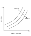
- FIG. 2 is a diagram showing the cathode flow rate necessary for maintaining the internal resistance of the fuel cell stack at a certain value in accordance with the stack inlet humidity RHc of the cathode gas.
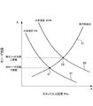
- FIG. 3 is a diagram showing the cathode flow rate when the cathode pressure, the stack temperature, and the atmospheric humidity each show a certain value according to the stack inlet humidity RHc of the cathode gas.
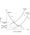
- FIG. 4 is a diagram illustrating a method for estimating the cathode flow rate based on the cathode pressure, the stack temperature, and the internal resistance.
- FIG. 5 is a diagram for explaining the wetting control of the electrolyte membrane when the actual internal resistance is larger than the target internal resistance.
- FIG. 6 is a diagram for explaining the wetting control of the electrolyte membrane when the actual internal resistance is larger than the target internal resistance.
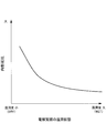
- FIG. 7 is a diagram showing the relationship between the wet state of the electrolyte membrane and the internal resistance.
- FIG. 8 is a map for estimating the cathode flow rate based on the rotational speed of the cathode compressor and the differential pressure across the cathode compressor.
- FIG. 9 is a diagram for explaining the wetting control of the electrolyte membrane when the actual internal resistance is smaller than the target internal resistance.
- FIG. 10 is a diagram for explaining the wetting control of the electrolyte membrane when the actual internal resistance is smaller than the target internal resistance.
- FIG. 11 is a flowchart for explaining control for controlling the wetting of the electrolyte membrane according to the first embodiment of the present invention.
- FIG. 12 is a flowchart for explaining the electrolyte membrane wetting control process.
- FIG. 13 is a flowchart illustrating control of the cathode compressor according to the second embodiment of the present invention.
- an electrolyte membrane is sandwiched between an anode electrode (fuel electrode) and a cathode electrode (oxidant electrode), an anode gas containing hydrogen in the anode electrode (fuel gas), and a cathode gas containing oxygen in the cathode electrode (oxidant) Electricity is generated by supplying gas.
- the electrode reaction that proceeds in both the anode electrode and the cathode electrode is as follows.
- Anode electrode 2H 2 ⁇ 4H + + 4e ⁇ (1)
- Cathode electrode 4H + + 4e ⁇ + O 2 ⁇ 2H 2 O (2)
- the fuel cell generates an electromotive force of about 1 volt by the electrode reactions (1) and (2).
- FIG. 1 is a schematic diagram of a fuel cell system 100 according to an embodiment of the present invention.
- the fuel cell system 100 includes a fuel cell stack 1, an anode gas supply / discharge device 2, a cathode gas supply / discharge device 3, a stack cooling device 4, and a controller 5.
- the fuel cell stack 1 is formed by stacking a plurality of fuel cells.
- the fuel cell stack 1 generates electric power by receiving supply of anode gas and cathode gas, and a motor (not shown) required to drive the generated electric power. Supplied to various electrical components such as
- the anode gas supply / discharge device 2 includes a high pressure tank 21, an anode gas supply passage 22, an anode pressure regulating valve 23, an anode gas discharge passage 24, an anode gas recirculation passage 25, a recycle compressor 26, a discharge valve 27, Is provided.
- the high-pressure tank 21 stores the anode gas supplied to the fuel cell stack 1 while maintaining the high-pressure state.
- the anode gas supply passage 22 is a passage through which the anode gas supplied to the fuel cell stack 1 flows. One end of the anode gas supply passage 22 is connected to the high-pressure tank 21 and the other end is connected to the anode gas inlet hole 11 of the fuel cell stack 1.
- the anode pressure regulating valve 23 is provided in the anode gas supply passage 22.
- the anode pressure regulating valve 23 is controlled to be opened and closed by the controller 5 and adjusts the pressure of the anode gas flowing out from the high-pressure tank 21 to the anode gas supply passage 22 to a desired pressure.
- the anode gas discharge passage 24 is a passage through which the anode off gas discharged from the fuel cell stack 1 flows. One end of the anode gas discharge passage 24 is connected to the anode gas outlet hole 12 of the fuel cell stack 11 and the other end is an open end.
- the anode off gas is a mixed gas of excess anode gas that has not been used in the electrode reaction and an inert gas such as nitrogen that has leaked from the cathode side.
- the anode gas recirculation passage 25 is a passage for returning the anode off gas discharged to the anode gas discharge passage 24 to the anode gas supply passage 22.
- One end of the anode gas recirculation passage 25 is connected to the anode gas discharge passage 24 upstream of the discharge valve 27, and the other end is connected to the anode gas supply passage 22 downstream of the anode pressure regulating valve 23.
- the recycle compressor 26 is provided in the anode gas recirculation passage 25.
- the recycle compressor 26 returns the anode off gas discharged to the anode gas discharge passage 24 to the anode gas supply passage 22.
- the exhaust valve 27 is provided in the anode gas discharge passage 24 on the downstream side of the connection portion between the anode gas discharge passage 24 and the anode gas recirculation passage 25.
- the discharge valve 27 is controlled to be opened and closed by the controller 5, and discharges anode off gas and condensed water to the outside of the fuel cell system 100.
- the cathode gas supply / discharge device 3 includes a cathode gas supply passage 31, a cathode gas discharge passage 32, a filter 33, a cathode compressor 34, an air flow sensor 35, and a water recovery device (Water ⁇ Recovery Device; hereinafter referred to as “WRD”). ) 36, a cathode pressure regulating valve 37, a first pressure sensor 38, and a second pressure sensor 39.
- a cathode gas supply passage 31 includes a cathode gas supply passage 31, a cathode gas discharge passage 32, a filter 33, a cathode compressor 34, an air flow sensor 35, and a water recovery device (Water ⁇ Recovery Device; hereinafter referred to as “WRD”).
- WDD Water ⁇ Recovery Device
- the cathode gas supply passage 31 is a passage through which the cathode gas supplied to the fuel cell stack 1 flows.
- the cathode gas supply passage 31 has one end connected to the filter 33 and the other end connected to the cathode gas inlet hole 13 of the fuel cell stack 1.
- the cathode gas discharge passage 32 is a passage through which the cathode off gas discharged from the fuel cell stack 1 flows. One end of the cathode gas discharge passage 32 is connected to the cathode gas outlet hole 14 of the fuel cell stack 1, and the other end is an open end.
- the cathode off gas is a mixed gas of the cathode gas and water vapor generated by the electrode reaction.
- the filter 33 removes foreign matters in the cathode gas taken into the cathode gas supply passage 31.
- the cathode compressor 34 is provided in the cathode gas supply passage 31.
- the cathode compressor 34 takes air (outside air) as cathode gas into the cathode gas supply passage 31 through the filter 33 and supplies the air to the fuel cell stack 1.
- the air flow sensor 35 is provided in the cathode gas supply passage 31 downstream of the cathode compressor 34.
- the air flow sensor 35 detects the flow rate of the cathode gas flowing through the cathode gas supply passage 31 (hereinafter referred to as “cathode flow rate”).
- the WRD 36 is a device that collects moisture in the cathode off-gas and humidifies the cathode gas with the collected moisture, and includes a humidifying unit 361 and a dehumidifying unit 362.
- the humidification unit 361 is provided in the cathode gas supply passage 31 downstream of the air flow sensor 35.
- the humidification unit 361 humidifies the cathode gas supplied to the fuel cell stack 1.
- the dehumidifying part 362 is provided in the cathode gas discharge passage 32.
- the dehumidifying unit 362 dehumidifies the cathode off gas flowing through the cathode gas discharge passage 32 and supplies the recovered water vapor to the humidifying unit 361.
- the cathode pressure regulating valve 37 is provided in the cathode gas discharge passage 32 downstream of the dehumidifying part 362 of the WRD 36.
- the cathode pressure regulating valve 37 is controlled to be opened and closed by the controller 5 and adjusts the pressure of the cathode gas (cathode pressure) supplied to the fuel cell stack 1 to a desired pressure.
- the first pressure sensor 38 is provided in the cathode supply passage 31 upstream of the cathode compressor 34, and detects the pressure of the cathode gas.
- the second pressure sensor 39 is provided in the cathode gas supply passage 31 downstream of the humidifying part 361 of the WRD 36.
- the pressure sensor 39 detects the pressure of the cathode gas supplied to the fuel cell stack 1 (hereinafter referred to as “cathode pressure”).
- the stack cooling device 4 is a device that cools the fuel cell stack 1 and maintains the fuel cell stack 1 at a temperature suitable for power generation.
- the stack cooling device 4 includes a cooling water circulation passage 41, a radiator 42, a bypass passage 43, a three-way valve 44, a cooling water circulation pump 45, and a water temperature sensor 46.
- the cooling water circulation passage 41 is a passage through which cooling water for cooling the fuel cell stack 11 circulates.
- the radiator 42 is provided in the cooling water circulation passage 41.
- the radiator 42 cools the cooling water discharged from the fuel cell stack 1.
- the bypass passage 43 has one end connected to the cooling water circulation passage 41 and the other end connected to the three-way valve 44 so that the cooling water can be circulated by bypassing the radiator 42.
- the three-way valve 44 is provided in the cooling water circulation passage 41 on the downstream side of the radiator 42.
- the three-way valve 44 switches the cooling water circulation path according to the temperature of the cooling water. Specifically, when the temperature of the cooling water is relatively high, the cooling water circulation path is such that the cooling water discharged from the fuel cell stack 1 is supplied again to the fuel cell stack 1 via the radiator 42. Switch. On the contrary, when the temperature of the cooling water is relatively low, the cooling water discharged from the cooling water discharged from the fuel cell stack 1 flows through the bypass passage 43 without passing through the radiator 42 and is again returned to the fuel cell stack 1. The cooling water circulation path is switched so as to be supplied.
- the cooling water circulation pump 45 is provided in the cooling water circulation passage 41 on the downstream side of the three-way valve 44 and circulates the cooling water.
- the water temperature sensor 46 is provided in the cooling water circulation passage 41 on the upstream side of the radiator 42.
- the water temperature sensor 46 detects the temperature of the cooling water discharged from the fuel cell stack 1 (hereinafter referred to as “stack temperature”).
- the controller 5 includes a microcomputer having a central processing unit (CPU), a read only memory (ROM), a random access memory (RAM), and an input / output interface (I / O interface).
- the controller 5 includes a current sensor 51 that detects the output current of the fuel cell stack 1, and the fuel cell stack 1 Signals from various sensors necessary for controlling the fuel cell system 100 such as a voltage sensor 52 for detecting the output voltage of the engine and an accelerator stroke sensor 53 for detecting the depression amount of the accelerator pedal are input.
- the controller 5 calculates electric power (hereinafter referred to as “required output power”) necessary for driving the vehicle based on detection signals of these various sensors.
- the controller 5 sets the cathode flow rate, the cathode flow rate, and the cathode flow rate so that the electrolyte membrane of each fuel cell constituting the fuel cell stack 1 is appropriately humidified.
- the internal moisture content of the fuel cell stack 1 is controlled by controlling the pressure and the stack temperature.
- the wet state of the electrolyte membrane is known to correlate with the internal high frequency resistance (HFR) of the fuel cell stack 1 (hereinafter referred to as “internal resistance”).
- HFR high frequency resistance
- internal resistance increases and the output voltage of the fuel cell stack 1 decreases.
- the controller 5 controls the internal water content of the fuel cell stack 1 by controlling the cathode flow rate, the cathode pressure, and the stack temperature so that the internal resistance of the fuel cell stack 1 becomes a predetermined target internal resistance. is doing.
- the cathode compressor 34 in order to improve the fuel consumption of the fuel cell system 100, it is desirable to operate the cathode compressor 34 at a low speed by reducing the cathode flow rate as much as possible.
- the cathode flow rate it is necessary that at least the output power of the fuel cell stack 1 is not lower than the minimum required flow rate (hereinafter referred to as “minimum cathode flow rate”) in order to obtain the required output power. Therefore, when the internal resistance of the fuel cell stack 1 is converged to the target internal resistance, the cathode pressure and the stack temperature must be controlled after the cathode flow rate is lowered to the minimum cathode flow rate.
- the cathode flow rate detection accuracy by the air flow sensor 35 tends to decrease as the cathode flow rate decreases, when the cathode flow rate is lowered to the lowest cathode flow rate, the cathode flow rate can actually be lowered to the lowest cathode flow rate. There wasn't. That is, there is a problem that the cathode flow rate can be lowered only to a flow rate with a sufficient margin added to the minimum cathode flow rate, and the fuel consumption deteriorates.
- the cathode flow rate is accurately estimated, and the cathode compressor 34 is controlled so that the estimated cathode flow rate does not fall below the minimum cathode flow rate, and the cathode resistance is set to the target internal resistance as necessary. Control pressure and stack temperature.
- FIG. 2 is a diagram showing the cathode flow rate required to maintain the internal resistance of the fuel cell stack 1 at a certain value according to the stack inlet humidity of the cathode gas.
- the cathode flow rate required to maintain the internal resistance at a certain value increases as the stack inlet humidity of the cathode gas increases. Further, when the stack inlet humidity of the cathode gas is the same, the required cathode flow rate is increased when the internal resistance is maintained at a high value.
- the electrolyte membrane gets wet as the stack inlet humidity of the cathode gas increases, and in order to maintain the internal resistance at a constant value, the cathode flow rate is correspondingly increased as the stack inlet humidity increases. This is because the electrolyte membrane needs to be increased and dried.
- FIG. 3 is a diagram showing the cathode flow rate when the cathode pressure, the stack temperature, and the atmospheric humidity each show a certain value according to the stack inlet humidity of the cathode gas.
- the lower the cathode flow rate the higher the stack inlet humidity of the cathode gas.
- the higher the cathode pressure, the lower the stack temperature, and the higher the atmospheric humidity the higher the stack inlet humidity of the cathode gas. That is, as the parameters of the cathode pressure, the stack temperature, and the atmospheric humidity change in the direction of increasing the internal moisture content of the fuel cell stack 1, the stack inlet humidity of the cathode gas increases.
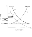
- FIG. 4 is a diagram for explaining a method for estimating the cathode flow rate based on the cathode pressure, the stack temperature, and the internal resistance.
- each of the cathode pressure, the stack temperature, and the internal resistance is detected, but the atmospheric humidity is not detected.
- a solid line A1 shown in FIG. 4 can be drawn by obtaining the relationship of FIG.
- a solid line A1 is a line indicating the cathode flow rate estimated from the detected current internal resistance (hereinafter referred to as “real internal resistance”) according to the stack inlet humidity of the cathode gas.
- the solid line B1 is a line showing the cathode flow rate estimated from the detected cathode pressure and the stack temperature when the atmospheric humidity is assumed to be 0% according to the stack inlet humidity of the cathode gas.
- a solid line B2 indicates a cathode flow rate estimated from the detected cathode pressure and the stack temperature when the atmospheric humidity is assumed to be 100% in accordance with the stack inlet humidity of the cathode gas.
- the actual cathode flow rate (hereinafter referred to as “actual cathode flow rate”) is at least the cathode flow rate (hereinafter referred to as “actual cathode flow rate lower limit value”) at the intersection C1 between the solid line A1 and the solid line B1, and the solid line A1 and the solid line B2.
- the cathode flow rate at the intersection C2 (hereinafter referred to as “the actual cathode flow rate upper limit value”).
- the cathode compressor 34 is controlled so that the lower limit value of the actual cathode flow rate does not fall below the minimum cathode flow rate, at least the actual cathode flow rate does not fall below the minimum cathode flow rate.
- the lower limit value of the actual cathode flow rate is basically set as the estimated value of the cathode flow rate, and the internal resistance is adjusted as necessary while controlling the cathode compressor 34 so that the lower limit value of the actual cathode flow rate does not fall below the minimum cathode flow rate.
- the cathode pressure and the stack temperature are controlled to achieve the target internal resistance.
- FIG. 5 and FIG. 6 are diagrams for explaining the wetting control of the electrolyte membrane when the actual internal resistance is larger than the target internal resistance.
- a solid line A2 indicates a cathode flow rate necessary for maintaining the internal resistance at the target internal resistance in accordance with the stack inlet humidity of the cathode gas.
- the solid line A1 is a line showing the cathode flow rate estimated from the detected current internal resistance (hereinafter referred to as “actual internal resistance”) in accordance with the stack inlet humidity of the cathode gas, as in FIG. .
- the solid line B1 shows the cathode flow rate estimated from the detected cathode pressure and the stack temperature when the atmospheric humidity is assumed to be 0%, according to the stack inlet humidity of the cathode gas. is there.
- target cathode flow rate lower limit the cathode flow rate at the intersection C3 between the solid line A2 and the solid line B1 is equal to or higher than the minimum cathode flow rate.
- the actual internal resistance can be converged to the target internal resistance by controlling the cathode compressor 34 such that the cathode flow rate is reduced by the difference between the actual cathode flow rate lower limit value and the target cathode flow rate lower limit value.
- the cathode flow rate when the target cathode flow rate lower limit value is smaller than the minimum cathode flow rate, the cathode flow rate cannot be reduced to the target cathode flow rate lower limit value, and can only be reduced to the minimum cathode flow rate. . This is because if the cathode flow rate is decreased to the target cathode flow rate lower limit value when the target cathode flow rate lower limit value is smaller than the minimum cathode flow rate, the output power becomes lower than the required output power.
- the cathode compressor 34 after controlling the cathode compressor 34 so that the sword flow rate is decreased by the difference between the actual cathode flow rate lower limit value and the minimum cathode flow rate, one or both of the cathode pressure and the stack temperature are controlled.
- the internal resistance is converged to the target internal resistance.
- the solid line B1 is moved to the solid line B1 ', and the internal resistance is converged to the target internal resistance.
- the solid line B1 ' is a line at which the cathode flow rate at the intersection C4 with the solid line A2 is the lowest cathode flow rate.
- FIG. 7 is a graph showing the relationship between the wet state of the electrolyte membrane and the internal resistance.
- the internal resistance of the fuel cell stack 1 varies depending on the wet state of the electrolyte membrane, and becomes higher as the electrolyte membrane is dried.
- the electrolyte membrane has a low degree of wetness, that is, when the electrolyte membrane is relatively dry, the change width of the internal resistance that changes in response to the change in the wet state of the electrolyte membrane becomes large.
- the electrolyte membrane is highly wet, that is, when the electrolyte membrane is relatively wet, the change width of the internal resistance when the wet state of the electrolyte membrane changes is small.
- the cathode flow rate is estimated based on the cathode pressure, the stack temperature, and the actual internal resistance when the electrolyte membrane is relatively wet and the actual internal resistance is small, the estimation accuracy may be reduced.
- the cathode flow rate is exceptionally referred to the map of FIG. 8 based on the rotational speed of the cathode compressor 34 and the differential pressure across the cathode compressor 34. Is estimated.
- FIG. 8 is a map for estimating the cathode flow rate based on the rotational speed of the cathode compressor 34 and the differential pressure across the cathode compressor 34.
- FIG. 9 and FIG. 10 are diagrams for explaining the wetting control of the electrolyte membrane when the actual internal resistance is smaller than the target internal resistance.
- the solid line A2 is a line indicating the cathode flow rate necessary for maintaining the internal resistance at the target internal resistance in accordance with the stack inlet humidity of the cathode gas, as in FIG. Similarly to FIG. 4, when the atmospheric humidity is assumed to be 0%, the cathode flow rate estimated from the detected cathode pressure and the stack temperature is a line corresponding to the stack inlet humidity of the cathode gas.
- an estimated value of the cathode flow rate (hereinafter referred to as an estimated value based on the minimum cathode flow rate, the rotational speed of the cathode compressor 34, and the differential pressure across the cathode 34).
- the cathode compressor 34 is controlled such that the cathode flow rate is increased by the difference between the “cathode flow rate estimated value”. Thereafter, the cathode pressure is increased or the stack temperature is lowered to move the solid line B1 to the solid line B1 ', thereby converging the internal resistance to the target internal resistance.
- the cathode compressor 34 is set so that the cathode flow rate increases by the difference between the minimum cathode flow rate and the estimated cathode flow rate. Control. Thereafter, by lowering the cathode pressure or raising the stack temperature, the solid line B1 is moved to the solid line B1 ', and the internal resistance is converged to the target internal resistance.
- FIG. 11 is a flowchart for explaining the wetting control of the electrolyte membrane according to the present embodiment.
- step S1 the controller 5 reads the detection signals of various sensors and detects the operating state of the fuel cell system 100.
- step S2 the controller 5 calculates the required output power based on the operating state of the fuel cell system 100.
- step S3 the controller 5 calculates the minimum cathode flow rate based on the required output power.
- the minimum cathode flow rate decreases as the required output power decreases.
- step S4 the controller 5 detects the actual internal resistance of the fuel cell stack 1.
- a DC / DC converter (not shown) is controlled to superimpose an alternating current on the output current of the fuel cell stack 1, and the voltage value of the fuel cell stack 11 at that time is detected by a voltage sensor. . Then, the voltage amplitude of the superimposed alternating current is calculated based on the voltage value, and the internal resistance of the fuel cell is calculated by dividing the voltage amplitude by the current amplitude of the superimposed alternating current.
- step S5 the controller 5 calculates the actual cathode flow rate lower limit value based on the cathode pressure, the stack temperature, and the actual internal resistance.
- step S6 the controller 5 calculates a target cathode flow rate lower limit value based on the cathode pressure, the stack temperature, and a predetermined target internal resistance set in advance.
- step S7 the controller 5 determines whether the actual internal resistance is equal to the target internal resistance. Specifically, if the absolute value of the difference between the actual internal resistance and the target internal resistance is within a predetermined value, it is determined that the actual internal resistance and the target internal resistance are equal. If the actual internal resistance is equal to the target internal resistance, the controller 5 ends the current process. On the other hand, if the actual internal resistance is not equal to the target internal resistance, the process of step S8 is performed.
- step S8 the controller 5 performs a wetness control process for the electrolyte membrane. Details of the electrolyte membrane wetting control process will be described later with reference to FIG.
- FIG. 12 is a flowchart for explaining the electrolyte membrane wetting control process.
- step S81 the controller 5 determines whether or not the actual internal resistance is larger than the target internal resistance. If the actual internal resistance is greater than the target internal resistance, the controller 5 performs the process of step S82. On the other hand, if the actual internal resistance is smaller than the target internal resistance, the process of step S86 is performed.
- step S82 the controller 5 determines whether or not the target cathode flow rate lower limit is equal to or higher than the minimum cathode flow rate. If the target cathode flow rate lower limit is equal to or greater than the minimum cathode flow rate, the controller 5 performs the process of step S83. On the other hand, if the target cathode flow rate lower limit is smaller than the minimum cathode flow rate, the process of step S84 is performed.
- step S83 the controller 5 controls the cathode compressor 34 so that the cathode flow rate is reduced by the difference amount between the actual cathode flow rate lower limit value and the target cathode flow rate lower limit value. As a result, the internal resistance is converged to the target internal resistance (see FIG. 5).
- step S84 the controller 5 controls the cathode compressor 34 so that the cathode flow rate is reduced by the difference between the actual cathode flow rate lower limit value and the minimum cathode flow rate (see FIG. 6).
- step S85 the controller 5 controls one or both of the cathode pressure and the stack temperature so that the internal resistance becomes the target internal resistance. Specifically, the cathode pressure is increased when the cathode pressure is controlled, and the stack temperature is decreased when the stack temperature is controlled. Thereby, the internal resistance is converged to the target internal resistance (see FIG. 6).
- step S86 the controller 5 refers to the map of FIG. 9 and calculates a cathode flow rate estimated value based on the rotational speed of the cathode compressor 34 and the differential pressure across the cathode compressor 34.
- step S87 the controller 5 controls the cathode compressor 34 so that the cathode flow rate is increased by the difference between the minimum cathode flow rate and the estimated cathode flow rate (see FIGS. 8 and 9).
- step S88 the controller 5 determines whether or not the minimum cathode flow rate is larger than the target cathode flow rate lower limit value. If the minimum cathode flow rate is larger than the target cathode flow rate lower limit value, the controller 5 performs the process of step S89. On the other hand, if the minimum cathode gas flow rate is smaller than the target cathode flow rate, the process of step S90 is performed.
- step S89 the controller 5 controls one or both of the cathode pressure and the stack temperature so that the internal resistance becomes the target internal resistance. Specifically, the cathode pressure is increased when the cathode pressure is controlled, and the stack temperature is decreased when the stack temperature is controlled (see FIG. 8).
- step S90 the controller 5 controls one or both of the cathode pressure and the stack temperature so that the internal resistance becomes the target internal resistance. Specifically, the cathode pressure is lowered when controlling the cathode pressure, and the stack temperature is raised when controlling the stack temperature (see FIG. 9).
- the cathode flow rate detected by the air flow sensor 35 When control is performed so that the cathode flow rate detected by the air flow sensor 35 does not fall below the minimum cathode flow rate, the cathode flow rate is only increased up to a flow rate obtained by adding a sufficient margin to the minimum cathode flow rate due to the detection accuracy of the air flow sensor 35. I could n’t lower it.
- the current cathode flow rate that takes the lowest value that is, the actual cathode flow rate lower limit value is calculated. Is the estimated value of the cathode flow rate.
- the cathode flow rate can be accurately estimated, so that the cathode flow rate is closer to the minimum cathode flow rate than when the cathode flow rate detected by the air flow sensor 35 is controlled so as not to fall below the minimum cathode flow rate. Can be lowered. Therefore, since the cathode compressor 34 can be operated at a low rotation, the fuel consumption of the fuel cell system 100 can be improved.
- the internal resistance is reduced as necessary while controlling the cathode compressor 34 so that the lower limit value of the actual cathode flow rate does not fall below the minimum cathode flow rate determined according to the operation state of the fuel cell system 100.
- the cathode pressure and stack temperature were controlled to achieve the target internal resistance.
- the wet state of the electrolyte membrane can be maintained in an optimum state, the power generation efficiency of the fuel cell system 100 can be improved.
- the internal resistance of the fuel cell stack 1 is larger than a predetermined value, there is a risk that the estimation accuracy when the cathode flow rate is estimated based on the cathode pressure, the stack temperature, and the internal resistance may be reduced. Is to estimate the cathode flow rate based on the rotational speed of the cathode compressor 34 and the differential pressure across it.
- the estimation accuracy of the cathode flow rate can be maintained, so that the cathode flow rate can be reliably prevented from falling below the minimum cathode flow rate, and the cathode compressor 34 can be operated at a low rotation speed.
- the fuel efficiency of the battery system 100 can be improved.
- the cathode compressor 34 is feedback-controlled using the estimated cathode flow rate instead of the cathode flow rate detected by the air flow sensor 35.
- the same reference numerals are used for portions that perform the same functions as those in the first embodiment described above, and repeated descriptions are omitted as appropriate.
- the cathode flow rate detection accuracy by the air flow sensor 35 tends to decrease as the cathode flow rate decreases.
- the cathode compressor 34 is fed back using the estimated cathode flow rate in a region where the accuracy of cathode flow rate detection by the air flow sensor 35 decreases, that is, in a region where the cathode flow rate detected by the air flow sensor 35 is less than a predetermined amount. Control.
- the estimated cathode flow rate and the target value of the cathode gas supplied to the fuel cell stack 1 (hereinafter referred to as “target cathode flow rate”).
- Feedback control of the cathode compressor 34 is performed so that the estimated cathode flow rate becomes the target cathode flow rate.
- the cathode flow rate detected by the airflow sensor 35 is equal to or larger than a predetermined amount, the cathode flow rate is detected so that the detected cathode flow rate becomes the target cathode flow rate based on the cathode flow rate detected by the air flow sensor 35 and the target cathode flow rate.
- the compressor 34 is feedback-controlled.
- FIG. 13 is a flowchart illustrating the control of the cathode compressor 34 according to the present embodiment.
- step S21 the controller 5 calculates a target cathode flow rate based on the operating state of the fuel cell system 100.
- the target cathode flow rate is a flow rate that can prevent flooding while satisfying the target output power.
- step S22 the controller 5 sets the actual cathode flow rate lower limit calculated based on the cathode pressure, the stack temperature, and the actual internal resistance as the estimated value of the cathode flow rate.
- step S23 the controller 5 determines whether or not the cathode flow rate detected by the air flow sensor 35 is less than a predetermined amount. If the cathode flow rate detected by the air flow sensor 35 is less than the predetermined amount, the controller 5 performs the process of step S24. On the other hand, if the cathode flow rate detected by the air flow sensor 35 is greater than or equal to a predetermined amount, the process of step S25 is performed.
- step S24 the controller 5 feedback-controls the cathode compressor 34 based on the estimated value of the cathode flow rate and the target cathode flow rate so that the estimated value of the cathode flow rate becomes the target cathode flow rate.
- step S25 the controller 5 feedback-controls the cathode compressor 34 based on the cathode flow rate and the target cathode flow rate detected by the air flow sensor 35 so that the detected cathode flow rate becomes the target cathode flow rate.
- the cathode compressor 34 is set to the target cathode flow rate using the estimated cathode flow rate with higher accuracy instead of the cathode flow rate detected by the air flow sensor 35.
- the cathode compressor 34 can be operated at a low speed, and the fuel cell system 100 fuel efficiency can be improved.
- the estimation accuracy when the cathode flow rate is estimated based on the cathode pressure, the stack temperature, and the actual internal resistance when the actual internal resistance is relatively small, the estimation accuracy may be reduced.
- the cathode flow rate was estimated according to the operating state of the cathode compressor 34.
- the minimum cathode flow rate is corrected to be higher, and the cathode flow rate is estimated based on the cathode pressure, stack temperature, and actual internal resistance regardless of the size of the actual internal resistance. good. By doing so, even if the estimation accuracy of the cathode flow rate is somewhat deteriorated, it is possible to suppress the actual cathode flow rate from being lower than the minimum cathode flow rate, and as a result, it is possible to prevent the power generation efficiency from being deteriorated.
- the cathode flow rate is estimated based on the cathode pressure, the stack temperature, and the actual internal resistance, assuming that the atmospheric humidity is 0%.
- the estimated cathode flow rate may be corrected according to the detected value of the humidity sensor. Specifically, correction may be made so that the estimated cathode flow rate increases as the atmospheric humidity increases. Thereby, the cathode flow rate can be estimated with higher accuracy.
- the wetting control of the electrolyte membrane may be performed only in a region where the detection accuracy of the airflow sensor 35 is low.
Landscapes
- Life Sciences & Earth Sciences (AREA)
- Engineering & Computer Science (AREA)
- Manufacturing & Machinery (AREA)
- Sustainable Development (AREA)
- Sustainable Energy (AREA)
- Chemical & Material Sciences (AREA)
- Chemical Kinetics & Catalysis (AREA)
- Electrochemistry (AREA)
- General Chemical & Material Sciences (AREA)
- Fuel Cell (AREA)
Abstract
Description
燃料電池は電解質膜をアノード電極(燃料極)とカソード電極(酸化剤極)とによって挟み、アノード電極に水素を含有するアノードガス(燃料ガス)、カソード電極に酸素を含有するカソードガス(酸化剤ガス)を供給することによって発電する。アノード電極及びカソード電極の両電極において進行する電極反応は以下の通りである。
カソード電極 : 4H+ +4e- +O2 →2H2O …(2)
次に、本発明の第2実施形態について説明する。本実施形態は、エアフローセンサ35の検出精度が低い領域では、エアフローセンサ35で検出したカソード流量ではなく、推定したカソード流量を用いてカソードコンプレッサ34をフィードバック制御する。なお、以下の各実施形態では上述した第1実施形態と同様の機能を果たす部分には、同一の符号を用いて重複する説明を適宜省略する。
Claims (11)
- アノードガス及びカソードガスを燃料電池に供給して発電させる燃料電池システムであって、
前記燃料電池にカソードガスを供給するカソードガス供給部と、
前記燃料電池に供給する前記カソードガスの圧力を検出するカソード圧検出部と、
前記燃料電池の温度を検出する燃料電池温度検出部と、
前記燃料電池の内部抵抗を検出する内部抵抗検出部と、
前記燃料電池システムの運転状態に基づいて、前記燃料電池に供給する必要のある目標カソード流量を算出する目標カソード流量算出部と、
前記カソードガスの圧力、前記燃料電池の温度及び前記燃料電池の内部抵抗に応じて、前記カソードガスの流量を推定するカソード流量推定部と、
前記目標カソード流量と前記推定した前記カソードガスの流量とに基づいて、前記カソードガス供給部を制御するカソード流量制御部と、
を備える燃料電池システム。 - 前記カソード流量推定部は、
前記燃料電池の内部抵抗が高いときほど、前記カソードガスの流量の推定値を大きくする、
請求項1に記載の燃料電池システム。 - 前記カソード流量推定部は、
前記カソードガスの圧力が高いときほど、前記カソードガスの流量の推定値を大きくする、
請求項1又は請求項2に記載の燃料電池システム。 - 前記カソード流量推定部は、
前記燃料電池の温度が低いときほど、前記カソードガスの流量の推定値を大きくする、
請求項1から請求項3までのいずれか1つに記載の燃料電池システム。 - 前記カソード流量推定部は、
大気湿度が前記燃料電池を使用する外部環境における最低値であると仮定して、前記カソードガスの流量を推定する、
請求項1から請求項4までのいずれか1つに記載の燃料電池システム。 - 大気湿度を検出する大気湿度検出部を備え、
前記カソード流量推定部は、
前記カソードガスの圧力、前記燃料電池の温度及び前記燃料電池の内部抵抗に応じて推定したカソードガスの流量の推定値を、前記大気湿度が高いときほど大きくなるように補正する、
請求項1から請求項4までのいずれか1つに記載の燃料電池システム。 - 前記燃料電池の内部抵抗を所定の目標内部抵抗に制御する内部抵抗制御部を備え、
前記内部抵抗制御部は、
推定した前記カソードガスの流量と前記目標カソード流量とが等しい場合に、前記燃料電池の内部抵抗が前記目標内部抵抗よりも高いときは、前記カソードガスの圧力を高くすることで、前記燃料電池の内部抵抗を所定の目標内部抵抗に制御する、
請求項1から請求項6までのいずれか1つに記載の燃料電池システム。 - 前記燃料電池の内部抵抗を所定の目標内部抵抗に制御する内部抵抗制御部を備え、
前記内部抵抗制御部は、
推定した前記カソードガスの流量と前記目標カソード流量とが等しい場合に、前記燃料電池の内部抵抗が前記目標内部抵抗よりも高いときは、前記燃料電池の温度を低くすることで、前記燃料電池の内部抵抗を所定の目標内部抵抗に制御する、
請求項1から請求項6までのいずれか1つに記載の燃料電池システム。 - 前記カソード流量推定部は、
前記燃料電池の内部抵抗が所定値よりも高いときに、前記カソードガスの圧力、前記燃料電池の温度及び前記燃料電池の内部抵抗に応じて、前記カソードガスの流量を推定し、
前記燃料電池の内部抵抗が前記所定値よりも低いときは、前記燃料電池にカソードガスを圧送するコンプレッサの回転速度と前後差圧とに基づいて、前記カソードガスの流量を推定する、
請求項1から請求項8までのいずれか1つに記載の燃料電池システム。 - 前記目標カソード流量算出部は、
前記燃料電池の内部抵抗が高いときほど、前記最低カソード流量が高くなるように補正する、
請求項1から請求項7までのいずれか1つに記載の燃料電池システム。 - 前記燃料電池に供給する前記カソードガスの流量を検出するカソード流量検出部を備え、
前記カソード流量制御部は、
前記カソードガスの流量が所定量より低いときに、前記目標カソード流量と前記推定した前記カソードガスの流量とに基づいて前記カソードガス供給部を制御する、
請求項1から請求項10までのいずれか1つに記載の燃料電池システム。
Priority Applications (5)
| Application Number | Priority Date | Filing Date | Title |
|---|---|---|---|
| CN201380005206.7A CN104040771B (zh) | 2012-01-10 | 2013-01-10 | 燃料电池系统 |
| JP2013553302A JP5812118B2 (ja) | 2012-01-10 | 2013-01-10 | 燃料電池システム |
| EP13736353.7A EP2804246B8 (en) | 2012-01-10 | 2013-01-10 | Fuel cell system |
| US14/371,103 US9350033B2 (en) | 2012-01-10 | 2013-01-10 | Fuel cell system |
| CA2860966A CA2860966C (en) | 2012-01-10 | 2013-01-10 | Fuel cell system provided with a cathode flow rate control unit |
Applications Claiming Priority (2)
| Application Number | Priority Date | Filing Date | Title |
|---|---|---|---|
| JP2012-002278 | 2012-01-10 | ||
| JP2012002278 | 2012-01-10 |
Publications (1)
| Publication Number | Publication Date |
|---|---|
| WO2013105590A1 true WO2013105590A1 (ja) | 2013-07-18 |
Family
ID=48781534
Family Applications (1)
| Application Number | Title | Priority Date | Filing Date |
|---|---|---|---|
| PCT/JP2013/050261 Ceased WO2013105590A1 (ja) | 2012-01-10 | 2013-01-10 | 燃料電池システム |
Country Status (6)
| Country | Link |
|---|---|
| US (1) | US9350033B2 (ja) |
| EP (1) | EP2804246B8 (ja) |
| JP (1) | JP5812118B2 (ja) |
| CN (1) | CN104040771B (ja) |
| CA (1) | CA2860966C (ja) |
| WO (1) | WO2013105590A1 (ja) |
Cited By (4)
| Publication number | Priority date | Publication date | Assignee | Title |
|---|---|---|---|---|
| WO2015049964A1 (ja) * | 2013-10-01 | 2015-04-09 | 日産自動車株式会社 | 燃料電池システム |
| WO2015098291A1 (ja) * | 2013-12-25 | 2015-07-02 | トヨタ自動車株式会社 | 燃料電池システム |
| WO2016125231A1 (ja) * | 2015-02-02 | 2016-08-11 | 日産自動車株式会社 | 燃料電池システム及び燃料電池システムの制御方法 |
| CN106104881A (zh) * | 2014-03-13 | 2016-11-09 | 日产自动车株式会社 | 燃料电池系统 |
Families Citing this family (4)
| Publication number | Priority date | Publication date | Assignee | Title |
|---|---|---|---|---|
| US10522862B2 (en) * | 2014-08-11 | 2019-12-31 | Johnson Ip Holding, Llc | Thermo-electrochemical converter |
| KR102552146B1 (ko) | 2018-04-05 | 2023-07-05 | 현대자동차주식회사 | 연료전지 시스템의 운전 제어 장치 및 방법 |
| DE102022103159A1 (de) | 2022-02-10 | 2023-08-10 | Bayerische Motoren Werke Aktiengesellschaft | Verfahren und Vorrichtung zur Ermittlung des Oxidationsmittel-Massenstroms in einen Energiewandler |
| KR102672284B1 (ko) | 2022-06-21 | 2024-06-03 | 주식회사 엘지에너지솔루션 | 배터리 관리 장치 및 방법 |
Citations (4)
| Publication number | Priority date | Publication date | Assignee | Title |
|---|---|---|---|---|
| JP2006185605A (ja) * | 2004-12-24 | 2006-07-13 | Aisin Seiki Co Ltd | 流体送出手段の制御装置、および燃料電池システム |
| JP2006286436A (ja) | 2005-04-01 | 2006-10-19 | Denso Corp | 燃料電池システム |
| JP2008282781A (ja) * | 2007-05-14 | 2008-11-20 | Aisin Seiki Co Ltd | 流体送出装置、改質器および燃料電池システム |
| JP2009211935A (ja) * | 2008-03-04 | 2009-09-17 | Nissan Motor Co Ltd | 燃料電池システム |
Family Cites Families (9)
| Publication number | Priority date | Publication date | Assignee | Title |
|---|---|---|---|---|
| JP3894026B2 (ja) * | 2001-05-18 | 2007-03-14 | 株式会社デンソー | 燃料電池内部の水分測定方法 |
| JP3905800B2 (ja) * | 2002-07-17 | 2007-04-18 | 本田技研工業株式会社 | 燃料電池の保護装置 |
| US7862935B2 (en) | 2005-05-17 | 2011-01-04 | Gm Global Technology Operations, Inc. | Management via dynamic water holdup estimator in a fuel cell |
| US8158294B2 (en) * | 2006-01-13 | 2012-04-17 | Panasonic Corporation | Fuel cell system and method of operating fuel cell system |
| JP5011733B2 (ja) * | 2006-01-23 | 2012-08-29 | 日産自動車株式会社 | 燃料電池システム及び燃料電池の加湿状態判定方法 |
| JP2008305700A (ja) * | 2007-06-08 | 2008-12-18 | Honda Motor Co Ltd | 燃料電池システム |
| JP5080876B2 (ja) * | 2007-06-20 | 2012-11-21 | 本田技研工業株式会社 | 燃料電池システム |
| JP5509728B2 (ja) * | 2009-08-24 | 2014-06-04 | 日産自動車株式会社 | 燃料電池システム |
| US8932775B2 (en) * | 2010-05-28 | 2015-01-13 | Toyota Jidosha Kabushiki Kaisha | Method and apparatus for controlling the operation of a fuel cell |
-
2013
- 2013-01-10 US US14/371,103 patent/US9350033B2/en not_active Expired - Fee Related
- 2013-01-10 CN CN201380005206.7A patent/CN104040771B/zh not_active Expired - Fee Related
- 2013-01-10 EP EP13736353.7A patent/EP2804246B8/en not_active Not-in-force
- 2013-01-10 CA CA2860966A patent/CA2860966C/en active Active
- 2013-01-10 JP JP2013553302A patent/JP5812118B2/ja not_active Expired - Fee Related
- 2013-01-10 WO PCT/JP2013/050261 patent/WO2013105590A1/ja not_active Ceased
Patent Citations (4)
| Publication number | Priority date | Publication date | Assignee | Title |
|---|---|---|---|---|
| JP2006185605A (ja) * | 2004-12-24 | 2006-07-13 | Aisin Seiki Co Ltd | 流体送出手段の制御装置、および燃料電池システム |
| JP2006286436A (ja) | 2005-04-01 | 2006-10-19 | Denso Corp | 燃料電池システム |
| JP2008282781A (ja) * | 2007-05-14 | 2008-11-20 | Aisin Seiki Co Ltd | 流体送出装置、改質器および燃料電池システム |
| JP2009211935A (ja) * | 2008-03-04 | 2009-09-17 | Nissan Motor Co Ltd | 燃料電池システム |
Non-Patent Citations (1)
| Title |
|---|
| See also references of EP2804246A4 * |
Cited By (11)
| Publication number | Priority date | Publication date | Assignee | Title |
|---|---|---|---|---|
| WO2015049964A1 (ja) * | 2013-10-01 | 2015-04-09 | 日産自動車株式会社 | 燃料電池システム |
| CN105594043A (zh) * | 2013-10-01 | 2016-05-18 | 日产自动车株式会社 | 燃料电池系统 |
| US9780397B2 (en) | 2013-10-01 | 2017-10-03 | Nissan Motor Co., Ltd. | Fuel cell system |
| CN105594043B (zh) * | 2013-10-01 | 2017-10-20 | 日产自动车株式会社 | 燃料电池系统 |
| WO2015098291A1 (ja) * | 2013-12-25 | 2015-07-02 | トヨタ自動車株式会社 | 燃料電池システム |
| JP2015122285A (ja) * | 2013-12-25 | 2015-07-02 | トヨタ自動車株式会社 | 燃料電池システム |
| KR101845144B1 (ko) | 2013-12-25 | 2018-04-03 | 도요타지도샤가부시키가이샤 | 연료 전지 시스템 |
| US10069159B2 (en) | 2013-12-25 | 2018-09-04 | Toyota Jidosha Kabushiki Kaisha | Fuel cell system |
| CN106104881A (zh) * | 2014-03-13 | 2016-11-09 | 日产自动车株式会社 | 燃料电池系统 |
| EP3118922A4 (en) * | 2014-03-13 | 2017-01-18 | Nissan Motor Co., Ltd | Fuel cell system |
| WO2016125231A1 (ja) * | 2015-02-02 | 2016-08-11 | 日産自動車株式会社 | 燃料電池システム及び燃料電池システムの制御方法 |
Also Published As
| Publication number | Publication date |
|---|---|
| US20150004506A1 (en) | 2015-01-01 |
| CA2860966C (en) | 2017-01-03 |
| CN104040771A (zh) | 2014-09-10 |
| JP5812118B2 (ja) | 2015-11-11 |
| EP2804246A4 (en) | 2015-07-29 |
| US9350033B2 (en) | 2016-05-24 |
| JPWO2013105590A1 (ja) | 2015-05-11 |
| EP2804246B1 (en) | 2016-09-14 |
| EP2804246A1 (en) | 2014-11-19 |
| CA2860966A1 (en) | 2013-07-18 |
| EP2804246B8 (en) | 2016-10-19 |
| CN104040771B (zh) | 2016-08-17 |
Similar Documents
| Publication | Publication Date | Title |
|---|---|---|
| JP4877656B2 (ja) | 燃料電池システムおよびその電流制御方法 | |
| JP5812118B2 (ja) | 燃料電池システム | |
| CN104380510B (zh) | 燃料电池系统 | |
| EP2720306B1 (en) | Wet state control device for fuel cell | |
| JP2013258111A (ja) | 燃料電池システム | |
| EP2717371B1 (en) | Fuel cell system | |
| JP2013114992A (ja) | 燃料電池システム | |
| JP6079227B2 (ja) | 燃料電池システム | |
| WO2007116814A1 (ja) | 燃料電池システムおよびその制御方法 | |
| JP6304366B2 (ja) | 燃料電池システム | |
| JP6136185B2 (ja) | 燃料電池システム | |
| JP4675605B2 (ja) | 燃料電池の酸化剤供給装置 | |
| JP6094214B2 (ja) | 燃料電池システム | |
| JP6287010B2 (ja) | 燃料電池システム | |
| JP2020068112A (ja) | 燃料電池システム | |
| JP2015076246A (ja) | 燃料電池システム | |
| WO2014192649A1 (ja) | 燃料電池システム及び燃料電池システムの制御方法 |
Legal Events
| Date | Code | Title | Description |
|---|---|---|---|
| 121 | Ep: the epo has been informed by wipo that ep was designated in this application |
Ref document number: 13736353 Country of ref document: EP Kind code of ref document: A1 |
|
| DPE2 | Request for preliminary examination filed before expiration of 19th month from priority date (pct application filed from 20040101) | ||
| WWE | Wipo information: entry into national phase |
Ref document number: 14371103 Country of ref document: US |
|
| ENP | Entry into the national phase |
Ref document number: 2013553302 Country of ref document: JP Kind code of ref document: A |
|
| ENP | Entry into the national phase |
Ref document number: 2860966 Country of ref document: CA |
|
| NENP | Non-entry into the national phase |
Ref country code: DE |
|
| REEP | Request for entry into the european phase |
Ref document number: 2013736353 Country of ref document: EP |
|
| WWE | Wipo information: entry into national phase |
Ref document number: 2013736353 Country of ref document: EP |