WO2013105592A1 - 過給システムおよび過給システムの制御方法 - Google Patents
過給システムおよび過給システムの制御方法 Download PDFInfo
- Publication number
- WO2013105592A1 WO2013105592A1 PCT/JP2013/050274 JP2013050274W WO2013105592A1 WO 2013105592 A1 WO2013105592 A1 WO 2013105592A1 JP 2013050274 W JP2013050274 W JP 2013050274W WO 2013105592 A1 WO2013105592 A1 WO 2013105592A1
- Authority
- WO
- WIPO (PCT)
- Prior art keywords
- temperature
- target temperature
- value
- gate valve
- waste gate
- Prior art date
- Legal status (The legal status is an assumption and is not a legal conclusion. Google has not performed a legal analysis and makes no representation as to the accuracy of the status listed.)
- Ceased
Links
Images




Classifications
-
- F—MECHANICAL ENGINEERING; LIGHTING; HEATING; WEAPONS; BLASTING
- F02—COMBUSTION ENGINES; HOT-GAS OR COMBUSTION-PRODUCT ENGINE PLANTS
- F02B—INTERNAL-COMBUSTION PISTON ENGINES; COMBUSTION ENGINES IN GENERAL
- F02B37/00—Engines characterised by provision of pumps driven at least for part of the time by exhaust
- F02B37/12—Control of the pumps
- F02B37/22—Control of the pumps by varying cross-section of exhaust passages or air passages, e.g. by throttling turbine inlets or outlets or by varying effective number of guide conduits
-
- F—MECHANICAL ENGINEERING; LIGHTING; HEATING; WEAPONS; BLASTING
- F02—COMBUSTION ENGINES; HOT-GAS OR COMBUSTION-PRODUCT ENGINE PLANTS
- F02B—INTERNAL-COMBUSTION PISTON ENGINES; COMBUSTION ENGINES IN GENERAL
- F02B37/00—Engines characterised by provision of pumps driven at least for part of the time by exhaust
- F02B37/12—Control of the pumps
- F02B37/18—Control of the pumps by bypassing exhaust from the inlet to the outlet of turbine or to the atmosphere
- F02B37/183—Arrangements of bypass valves or actuators therefor
-
- F—MECHANICAL ENGINEERING; LIGHTING; HEATING; WEAPONS; BLASTING
- F02—COMBUSTION ENGINES; HOT-GAS OR COMBUSTION-PRODUCT ENGINE PLANTS
- F02B—INTERNAL-COMBUSTION PISTON ENGINES; COMBUSTION ENGINES IN GENERAL
- F02B39/00—Component parts, details, or accessories relating to, driven charging or scavenging pumps, not provided for in groups F02B33/00 - F02B37/00
- F02B39/16—Other safety measures for, or other control of, pumps
-
- F—MECHANICAL ENGINEERING; LIGHTING; HEATING; WEAPONS; BLASTING
- F02—COMBUSTION ENGINES; HOT-GAS OR COMBUSTION-PRODUCT ENGINE PLANTS
- F02D—CONTROLLING COMBUSTION ENGINES
- F02D41/00—Electrical control of supply of combustible mixture or its constituents
- F02D41/0002—Controlling intake air
- F02D41/0007—Controlling intake air for control of turbo-charged or super-charged engines
-
- F—MECHANICAL ENGINEERING; LIGHTING; HEATING; WEAPONS; BLASTING
- F02—COMBUSTION ENGINES; HOT-GAS OR COMBUSTION-PRODUCT ENGINE PLANTS
- F02D—CONTROLLING COMBUSTION ENGINES
- F02D41/00—Electrical control of supply of combustible mixture or its constituents
- F02D41/02—Circuit arrangements for generating control signals
- F02D41/14—Introducing closed-loop corrections
- F02D41/1438—Introducing closed-loop corrections using means for determining characteristics of the combustion gases; Sensors therefor
- F02D41/1444—Introducing closed-loop corrections using means for determining characteristics of the combustion gases; Sensors therefor characterised by the characteristics of the combustion gases
- F02D41/1446—Introducing closed-loop corrections using means for determining characteristics of the combustion gases; Sensors therefor characterised by the characteristics of the combustion gases the characteristics being exhaust temperatures
-
- F—MECHANICAL ENGINEERING; LIGHTING; HEATING; WEAPONS; BLASTING
- F02—COMBUSTION ENGINES; HOT-GAS OR COMBUSTION-PRODUCT ENGINE PLANTS
- F02D—CONTROLLING COMBUSTION ENGINES
- F02D41/00—Electrical control of supply of combustible mixture or its constituents
- F02D41/24—Electrical control of supply of combustible mixture or its constituents characterised by the use of digital means
- F02D41/2406—Electrical control of supply of combustible mixture or its constituents characterised by the use of digital means using essentially read only memories
- F02D41/2425—Particular ways of programming the data
- F02D41/2429—Methods of calibrating or learning
-
- Y—GENERAL TAGGING OF NEW TECHNOLOGICAL DEVELOPMENTS; GENERAL TAGGING OF CROSS-SECTIONAL TECHNOLOGIES SPANNING OVER SEVERAL SECTIONS OF THE IPC; TECHNICAL SUBJECTS COVERED BY FORMER USPC CROSS-REFERENCE ART COLLECTIONS [XRACs] AND DIGESTS
- Y02—TECHNOLOGIES OR APPLICATIONS FOR MITIGATION OR ADAPTATION AGAINST CLIMATE CHANGE
- Y02T—CLIMATE CHANGE MITIGATION TECHNOLOGIES RELATED TO TRANSPORTATION
- Y02T10/00—Road transport of goods or passengers
- Y02T10/10—Internal combustion engine [ICE] based vehicles
- Y02T10/12—Improving ICE efficiencies
Definitions
- the present invention relates to a supercharging system and a method for controlling the supercharging system.
- a supercharger is used for the purpose of increasing output by connecting to an engine or the like.
- the flow rate and pressure of the exhaust gas thereafter increase.
- the rotational force of the supercharger increases, the supercharging pressure further increases.
- some turbochargers have a function of bypassing a part of the exhaust gas from the engine to the downstream of the turbine and suppressing the pressure of the exhaust gas flowing into the turbine housing.
- the turbocharger having the above function is provided with a bypass passage that communicates the upstream and downstream of the turbine impeller. Further, a wastegate valve that opens and closes the bypass flow path is provided. The opening degree of the waste gate valve is adjusted by an actuator connected to the waste gate valve in accordance with the pressure in the compressor housing.
- Patent Document 1 proposes a supercharger having a function of resetting the relationship between the control amount of the waste gate valve and the opening degree in a timely manner.
- the temperature of the supercharger varies greatly depending on the usage status of the engine output connected to the supercharger, for example. Due to the thermal expansion accompanying this temperature change, the overall shape of the supercharger also changes, and the relative positions of the waste gate valve and the hole closed by the waste gate valve also change. Therefore, for example, even if the supercharger described in Patent Document 1 is used and the wastegate valve is controlled by an electric actuator, a leak occurs due to a temperature change for each use situation, or the wastegate valve closes the hole. There is a possibility that the opening degree cannot be adjusted properly, for example, the tightening force becomes too strong.
- An object of the present invention is to provide a supercharging system and a supercharging system control method capable of appropriately adjusting the opening degree of the waste gate valve regardless of the temperature of the supercharger.
- 1st aspect of this invention is a supercharging system, Comprising: The supercharger main body which has a compressor housing and a turbine housing, The turbine impeller in the said turbine housing, and the said compressor are rotatably supported by the said supercharger main body.
- a turbine shaft that connects the compressor impeller in the housing, a waste gate valve that bypasses a part of the fluid guided to the turbine impeller to the downstream of the turbine impeller, and the waste gate valve that opens and opens the waste gate valve.
- An electric actuator that adjusts the temperature, a temperature acquisition unit that acquires a target temperature that is either the temperature of the supercharger main body or a temperature that has a correlation with the temperature of the supercharger main body, and the target temperature Actuator control unit for controlling the electric actuator based on , And summarized in that it comprises a.
- the supercharging system may further include a storage unit that stores relationship information in which the correction value is associated with the target temperature.
- the correction value is a control value for the electric actuator when the waste gate valve is fully closed at the target temperature corresponding to the correction value, and when the waste gate valve is fully closed at the reference temperature. Is a difference value from a reference value that is a control value for the electric actuator.
- the actuator control unit specifies the correction value based on the relationship information from the target temperature acquired by the temperature acquisition unit, and adds and subtracts the specified correction value to a control input value for the electric actuator.
- the electric actuator may be controlled with a control value.
- the storage unit may store a table in which the target temperature and the correction value are associated with each other as the relation information.
- the storage unit may store an arithmetic expression capable of calculating the correction value from the target temperature as the relation information.
- a second aspect of the present invention is a control method for a supercharging system including an electric actuator that adjusts an opening degree of a waste gate valve that bypasses a fluid guided to a turbine impeller downstream of the turbine impeller.
- This control method acquires a target temperature which is either a temperature of a supercharger main body or a temperature having a correlation with the temperature of the supercharger main body, and controls the electric actuator based on the target temperature. This is the gist.
- the opening degree of the waste gate valve can be appropriately adjusted regardless of the temperature of the supercharger.
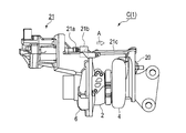
- FIG. 1 is a schematic sectional view of a supercharger.
- the direction of arrow F will be described as the front side of the supercharger C
- the direction of arrow R will be described as the rear side of the supercharger C.
- the supercharger C includes a supercharger main body 1.
- the supercharger main body 1 includes a bearing housing 2, a turbine housing 4, and a compressor housing 6.
- the turbine housing 4 is located on the front side of the bearing housing 2 and is connected by bolts 3.
- the compressor housing 6 is located on the rear side of the bearing housing 2 and is connected by a bolt 5.
- the bearing housing 2 has a bearing hole 2a.
- the bearing hole 2a penetrates the bearing housing 2 in the front-rear direction of the supercharger C.
- the turbine shaft 7 is inserted into the bearing hole 2a and is rotatably supported through the bearing.
- a turbine impeller 8 is integrally connected to a front end portion (one end) of the turbine shaft 7.
- the turbine impeller 8 is rotatably accommodated in the turbine housing 4.
- a compressor impeller 9 is integrally connected to the rear end (the other end) of the turbine shaft 7.
- the compressor impeller 9 is rotatably accommodated in the compressor housing 6.
- the compressor housing 6 has an intake port 10 that opens to the rear side of the supercharger C and is connected to an air cleaner (not shown).
- the intake port 10 opens to the rear side of the supercharger C and is connected to an air cleaner (not shown).
- the opposing surfaces of the two housings 2 and 6 form a diffuser flow path 11 that compresses and pressurizes air.
- the diffuser flow path 11 is formed in an annular shape from the radially inner side to the outer side of the turbine shaft 7 (compressor impeller 9), and communicates with the intake port 10 via the compressor impeller 9 on the radially inner side. Yes.
- the compressor housing 6 has an annular compressor scroll passage 12.
- the compressor scroll passage 12 is located on the radially outer side of the turbine shaft 7 (compressor impeller 9) with respect to the diffuser passage 11, communicates with the intake port of the engine, and also communicates with the diffuser passage 11. Therefore, when the compressor impeller 9 rotates, fluid is sucked into the compressor housing 6 from the intake port 10, and the sucked fluid is boosted in the diffuser flow path 11 and the compressor scroll flow path 12 and led to the intake port of the engine. It is burned.
- the turbine housing 4 has a discharge port 13.
- the discharge port 13 opens to the front side of the supercharger C and is connected to an exhaust gas purification device (not shown). Further, when the turbine housing 4 is connected to the bearing housing 2 by the bolt 3, the mutually facing surfaces of the two housings 2, 4 form a flow path 14.
- the flow path 14 is formed in an annular shape from the radially inner side to the outer side of the turbine shaft 7 (the turbine impeller 8).
- the turbine housing 4 has an annular turbine scroll passage 15.
- the turbine scroll passage 15 is located on the radially outer side of the turbine shaft 7 (turbine impeller 8) with respect to the passage 14, and a gas inlet 4a (see FIG. 3) through which exhaust gas discharged from the exhaust port of the engine is guided.
- the exhaust gas of the engine is guided from the gas inlet 4 a to the turbine scroll passage 15 and further to the discharge port 13 through the passage 14 and the turbine impeller 8.
- the exhaust gas rotates the turbine impeller 8.
- the rotational force of the turbine impeller 8 is transmitted to the compressor impeller 9 via the turbine shaft 7, and the compressor impeller 9 rotates.
- the intake fluid is boosted and guided to the intake port of the engine.
- FIG. 2 is a front view of the supercharger C
- FIG. 3 is a side view of the supercharger C.
- the turbine housing 4 is provided with a bypass hole 4 b.
- the bypass hole 4b penetrates from the wall portion between the gas inlet 4a and the turbine scroll passage 15 toward the surface where the discharge port 13 opens. A part of the fluid guided to the turbine impeller 8 can be bypassed (outflowed) downstream of the turbine impeller 8 through the bypass hole 4b.
- the waste gate valve 20 functions as an on-off valve that abuts the bypass hole 4b to close the bypass hole 4b or is spaced apart from the bypass hole 4b to open the bypass hole 4b. That is, the waste gate valve 20 bypasses part of the fluid guided to the turbine impeller 8 downstream of the turbine impeller 8.
- the waste gate valve 20 is connected to the electric actuator 21.
- the electric actuator 21 includes, for example, a movable portion 21a configured by a motor or the like, and a rod 21c connected to the movable portion 21a.
- a heat shield 21b is attached to the movable portion 21a.
- the heat shield 21b shields radiant heat from a heat source such as an engine. As shown in FIG. 2, the rod 21c moves in the direction indicated by the arrow A in conjunction with the operation of the movable portion 21a.
- One end of the connecting member 22 is rotatably supported at the tip of the rod 21c, and the other end of the connecting member 22 is fixed to one end of the shaft 23 held rotatably. Further, the other end of the shaft 23 is connected to the waste gate valve 20 via the mounting plate 24. Therefore, when the rod 21c moves in the direction indicated by the arrow A, the connecting member 22 rotates with the end portion fixed to the shaft 23 as the rotation axis. The shaft 23 rotates in the direction indicated by the arrow B in FIG. The opening degree of the waste gate valve 20 is adjusted by the rotation of the shaft 23.
- the electric actuator 21 adjusts the flow rate of the fluid (exhaust gas) that bypasses the turbine impeller 8 in accordance with the operation of the connecting member 22, and adjusts the pressure of the exhaust gas flowing into the turbine scroll passage 15 from the gas inlet 4 a.
- the rotational output of the turbine impeller 8 is adjusted.
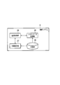
- FIG. 4 is a block diagram for explaining the control of the electric actuator 21 in the supercharging system S.
- the supercharging system S includes the supercharger C described above and an engine control device (ECU: Engine Control Unit) connected to the supercharger C.
- FIG. 4 shows functional units related to control of the electric actuator 21 in the ECU constituting the supercharging system S. In addition, description is abbreviate
- the functional unit related to the control of the electric actuator 21 is not limited to the configuration incorporated in the ECU, and may be incorporated in a separate control device.
- the target temperature is a temperature having a correlation with the temperature of the supercharger main body 1, and is, for example, a measured value of the temperature of the outer wall of the turbine housing 4 or the temperature of the surface of the rod 21c of the electric actuator 21.
- the target temperature may be a measured value of the temperature of the exhaust gas flowing into the turbine housing 4 or the temperature of the catalyst (exhaust gas purification device) connected to the supercharger C and provided in the exhaust path of the engine.
- the temperature acquisition unit 25 may always acquire the temperature of the temperature sensor, or may acquire only when there is an instruction to measure the temperature from the initial setting unit 27 or the actuator control unit 28.
- the storage unit 26 is composed of a storage medium such as a flash memory, for example.
- the storage unit 26 stores a reference value associated with a reference temperature (normal temperature in the present embodiment) in accordance with the control of the initial setting unit 27.
- the reference value is a control value (voltage) to the electric actuator 21 when the waste gate valve 20 is fully closed at the reference temperature.
- the storage unit 26 stores relationship information in which the correction value at the target temperature is associated with the target temperature in accordance with the control of the initial setting unit 27.
- the correction value is a difference value between the control value for the electric actuator 21 when the waste gate valve 20 is fully closed at the target temperature and the reference value.
- storage part 26 has memorize
- the reference value is determined as follows. First, the initial setting unit 27 causes the temperature acquisition unit 25 to acquire the target temperature, for example, in response to a user operation input. Next, the initial setting unit 27 sets the acquired target temperature as a reference temperature, and outputs a provisional control value at this temperature to the electric actuator 21. Here, the user performs an operation input to the initial setting unit 27 to finely adjust the control value so that the waste gate valve 20 is completely closed. Note that an operation program or the like may perform an operation input to the initial setting unit 27. The initial setting unit 27 stores the control value when the waste gate valve 20 is fully closed by this adjustment in the storage unit 26 as a reference value.
- the waste gate valve 20 When the waste gate valve 20 comes into contact with the bypass hole 4b and collides with the operation of the rod 21c of the electric actuator 21, the waste gate valve 20 is fully closed.
- the position of the rod 21c at which the waste gate valve 20 is fully closed is confirmed by, for example, a position sensor or a load sensor provided inside or outside the electric actuator.
- the hot state means a state (period) in which the supercharger C is placed at a temperature that causes thermal expansion or contraction. This is, for example, a state where the engine connected to the supercharger C is operating. In this case, high-temperature exhaust gas corresponding to the operating conditions is guided to the supercharger C, and the supercharger C is heated.
- the initial setting unit 27 causes the temperature acquisition unit 25 to acquire the target temperature, for example, in response to a user operation input.
- the temperature acquisition unit 25 outputs a control value based on the acquired target temperature to the electric actuator 21.
- a user or an operation program performs an operation input to the initial setting unit 27 so that the waste gate valve 20 is fully closed, and finely adjusts the control value. Then, the initial setting unit 27 derives a difference value between the control value when the waste gate valve 20 is fully closed by this adjustment and the reference value. Further, the initial setting unit 27 sets the derived difference value as a correction value, associates the correction value with the target temperature, and causes the storage unit 26 to store this combination as related information.
- the actuator control unit 28 controls the electric actuator 21 based on the target temperature acquired by the temperature acquisition unit 25. Specifically, the actuator control unit 28 specifies a correction value based on the target temperature acquired by the temperature acquisition unit 25 and the relationship information stored in the storage unit 26, and the control input value for the electric actuator 21 is The electric actuator 21 is controlled with a control value (voltage) derived by adding and subtracting the specified correction value.
- the control input value for the electric actuator 21 is derived based on the opening degree of the waste gate valve 20.
- the opening degree of the waste gate valve 20 is determined by the ECU in consideration of the engine speed, the engine supply / exhaust amount and the like.
- FIG. 5 is a flowchart for explaining a control method of the supercharging system S.
- FIG. 5 (a) shows the flow of the setting process of the supercharging system S at normal temperature
- FIG. 5 (b) shows the flow of the setting process of the supercharging system S at the hot time
- FIG. c) shows the flow of control processing of the supercharging system S during operation.
- the initial setting unit 27 acquires the target temperature from the temperature acquisition unit 25, and sets the acquired target temperature as the reference temperature (S200). Then, the initial setting unit 27 fully closes the waste gate valve 20 in accordance with, for example, user operation input or operation program input processing (S202). Further, the initial setting unit 27 stores the control value (voltage) to the electric actuator 21 when the waste gate valve 20 is fully closed in the storage unit 26 as a reference value (S204).
- the initial setting unit 27 acquires the target temperature from the temperature acquisition unit 25 during the hot time (S220).
- the initial setting unit 27 fully closes the waste gate valve 20 in accordance with, for example, a user operation input or an operation program input process, similarly to step S202 (S222).
- the initial setting unit 27 subtracts the control value for the electric actuator 21 at this time from the reference value stored in the storage unit 26 (S224), and associates this difference as a correction value with the target temperature in the storage unit 26. Store (S226).
- the processing shown in FIG. 5B is performed under a plurality of operating conditions, that is, at a plurality of different target temperatures.
- the actuator control part 28 acquires object temperature T from the temperature acquisition part 25 (S240). .
- the actuator control unit 28 refers to a table that is related information stored in the storage unit 26. In this table, for example, a correction value is associated with each predetermined range of the target temperature, and the actuator control unit 28 sets the correction value associated with the target temperature T acquired from the temperature acquisition unit 25 to the correction value. Obtained from the table (S242).
- the actuator control unit 28 adds the acquired correction value to the reference value stored in the storage unit 26, and derives an appropriate control value at the target temperature T (S244). Further, the actuator control unit 28 controls the electric actuator 21 with the derived control value to adjust the opening degree of the waste gate valve 20 (S246).
- the actuator control unit 28 controls the electric actuator 21 according to the target temperature. Therefore, the temperature of the supercharger main body 1 changes according to the use situation, and accordingly, the supercharger main body 1 and the electric actuator 21 are thermally expanded, and are bypass holes that are blocked by the waste gate valve 20 and the waste gate valve 20. Even if the relative position of 4b changes, the supercharging system S can adjust the opening degree of the waste gate valve 20 appropriately.
- the storage unit 26 may store an arithmetic expression capable of calculating a correction value from the target temperature as related information.
- FIG. 6 is a graph showing an example of the relationship between the target temperature and the correction value.
- the control value of the electric actuator 21 at the normal temperature T0 is used as a reference value, and a case where the correction value for the reference value and the target temperature are in a proportional relationship will be described as an example.
- the initial setting unit 27 performs the process shown in FIG. 5B under a plurality of operating conditions, and then approximates the correction value from the target temperature based on the target temperature and the correction value stored in the storage unit 26. Is calculated and stored in the storage unit 26.
- the actuator control unit 28 can specify that the correction value at the target temperature T1 is the correction value ⁇ a and the correction value at the target temperature T2 is the correction value ⁇ b by an arithmetic expression.
- the supercharging system S needs to store only the arithmetic expression as compared with the case where the table is stored in the storage unit 26, and the storage capacity required for the storage unit 26 is reduced. it can. Further, compared to the case where the correction value is specified based on the table, one correction value can be uniquely specified for one target temperature, and finer control can be realized.
- the supercharging system S does not need to perform a calculation process for deriving a control value from the target temperature, and can obtain a correction value only by referring to the table. Therefore, the supercharging system S can reduce a processing load compared with the case where the relationship information is an arithmetic expression. In addition, the supercharging system S can cope with the target information stored in the storage unit 26 as a simple table even if the relationship between the target temperature and the control value is so complex that it is difficult to express it with an arithmetic expression.
- the initial setting unit 27 is not limited to the configuration using the control value that fully closes the waste gate valve 20 at the normal temperature T0 as the reference temperature, and the target temperature at the time of operation, for example, the target temperature T1.
- a control value that sets the waste gate valve 20 at the target temperature T1 to be fully closed may be used as the reference value.
- this control value may be the upper limit value of the control value that fully closes the waste gate valve 20.
- the relative position of the waste gate valve 20 changes due to thermal expansion in a direction approaching the bypass hole 4b.
- control value and the correction value are represented by voltage, but may be represented by current. Further, the control value and the correction value may be expressed as an analog signal or a digital signal.
- the present invention can be used for a supercharging system for adjusting a flow rate for bypassing a fluid guided to a turbine impeller downstream of the turbine impeller and a control method for the supercharging system.
Landscapes
- Engineering & Computer Science (AREA)
- Chemical & Material Sciences (AREA)
- Combustion & Propulsion (AREA)
- Mechanical Engineering (AREA)
- General Engineering & Computer Science (AREA)
- Supercharger (AREA)
Description
本発明は、過給システムおよび過給システムの制御方法に関する。
過給機は、エンジン等に接続して出力を高める用途で用いられることが知られている。過給機の過給圧が高くなると、その後の排気ガスの流量や圧力が高まる。過給機の回転力が高まると、過給圧がさらに高まる。その結果、エンジンや過給機が損傷する可能性が高まる。そこで、過給機の中には、排気ガスの一部をエンジンからタービンの下流にバイパスさせ、タービンハウジングに流入する排気ガスの圧力を抑制する機能を備えたものがある。
上記の機能をもつ過給機には、タービンインペラの上流と下流とを連通するバイパス流路が設けられる。さらに、このバイパス流路を開閉するウェイストゲートバルブ(wastegate valve)が設けられている。そして、コンプレッサハウジング内の圧力に応じ、ウェイストゲートバルブに連結されたアクチュエータによってウェイストゲートバルブの開度が調節される。
過給機の形状が経年変化すると、ウェイストゲートバルブと、ウェイストゲートバルブで塞がれる孔の相対位置も変化する。そのため、アクチュエータが電動式の場合、ウェイストゲートバルブの制御を行っても、孔の開度を適切に調整できなくなる。特許文献1は、適時、ウェイストゲートバルブの制御量と開度との関係を設定し直す機能を備える過給機を提案している。
過給機の温度は、例えば、当該過給機に接続されたエンジン出力等の使用状況によって大きく変化する。この温度変化に伴う熱膨張によって、過給機全体の形状も変化し、ウェイストゲートバルブと、ウェイストゲートバルブで塞がれる孔の相対位置も変わる。そのため、例えば、特許文献1に記載の過給機を用い、電動式アクチュエータによってウェイストゲートバルブの制御を行っても、使用状況ごとの温度変化によって、リークが生じたり、ウェイストゲートバルブが孔を塞ぐ際の締め付け力が強くなり過ぎたりするなど、開度を適切に調整できなくなるおそれがある。
本発明の目的は、過給機の温度に関わらず、ウェイストゲートバルブの開度を適切に調整することができる過給システムおよび過給システムの制御方法を提供することである。
本発明の第1の態様は過給システムであって、コンプレッサハウジングおよびタービンハウジングを有する過給機本体と、前記過給機本体に回転自在に支持され、前記タービンハウジング内のタービンインペラと前記コンプレッサハウジング内のコンプレッサインペラとを連結するタービン軸と、前記タービンインペラに導かれる流体の一部をタービンインペラの下流にバイパスさせるウェイストゲートバルブと、前記ウェイストゲートバルブに連結され、該ウェイストゲートバルブの開度を調整する電動アクチュエータと、前記過給機本体の温度、または、該過給機本体の温度と相関関係を有する温度のいずれかである対象温度を取得する温度取得部と、前記対象温度に基づいて前記電動アクチュエータを制御するアクチュエータ制御部と、を備えることを要旨とする。
過給システムは、補正値がその対象温度に対応付けられた関係情報を記憶する記憶部をさらに備えてもよい。この場合、前記補正値は、前記補正値に対応する対象温度において前記ウェイストゲートバルブが全閉となるときの前記電動アクチュエータへの制御値と、基準温度において前記ウェイストゲートバルブが全閉となるときの前記電動アクチュエータへの制御値である基準値との差分値である。前記アクチュエータ制御部は、前記温度取得部によって取得された前記対象温度から前記関係情報に基づいて前記補正値を特定し、前記電動アクチュエータに対する制御の入力値に当該特定した補正値を加減算して導出される制御値で、前記電動アクチュエータを制御してもよい。
前記記憶部は、前記対象温度と前記補正値とが対応付けられたテーブルを前記関係情報として記憶していてもよい。
前記記憶部は、前記対象温度から前記補正値を算出可能な演算式を前記関係情報として記憶していてもよい。
本発明の第2の態様は、タービンインペラに導かれる流体を該タービンインペラの下流にバイパスさせるウェイストゲートバルブの開度を調整する電動アクチュエータを備えた過給システムの制御方法である。この制御方法は、過給機本体の温度、または、該過給機本体の温度と相関関係を有する温度のいずれかである対象温度を取得し、前記対象温度に基づいて前記電動アクチュエータを制御することを要旨とする。
本発明によれば、過給機の温度に関わらず、ウェイストゲートバルブの開度を適切に調整することができる。
以下に添付図面を参照しながら、本発明の一実施形態について説明する。かかる実施形態に示す寸法、材料、その他具体的な数値等は、発明の理解を容易とするための例示にすぎず、特に断る場合を除き、本発明を限定するものではない。なお、本明細書および図面において、実質的に同一の機能、構成を有する要素については、同一の符号を付することにより重複説明を省略し、また本発明に直接関係のない要素は図示を省略する。
図1は、過給機の概略断面図である。以下、矢印F方向を過給機Cの前側とし、矢印R方向を過給機Cの後側として説明する。図1に示すように、過給機Cは、過給機本体1を備える。過給機本体1は、ベアリングハウジング2と、タービンハウジング4と、コンプレッサハウジング6とを有する。タービンハウジング4はベアリングハウジング2の前側に位置し、ボルト3によって連結されている。コンプレッサハウジング6はベアリングハウジング2の後側に位置し、ボルト5によって連結されている。
ベアリングハウジング2には、軸受孔2aが形成されている。軸受孔2aは過給機Cの前後方向にベアリングハウジング2を貫通する。タービン軸7はこの軸受孔2aに挿入され、ベアリングを介して回転自在に支持されている。タービン軸7の前端部(一端)にはタービンインペラ8が一体的に連結されている。タービンインペラ8は、タービンハウジング4内に回転自在に収容されている。また、タービン軸7の後端部(他端)にはコンプレッサインペラ9が一体的に連結されている。コンプレッサインペラ9は、コンプレッサハウジング6内に回転自在に収容されている。
コンプレッサハウジング6は、過給機Cの後側に開口するとともに不図示のエアクリーナに接続される吸気口10を有する。吸気口10は、過給機Cの後側に開口し、不図示のエアクリーナに接続される。また、ボルト5によってコンプレッサハウジング6がベアリングハウジング2に連結されたとき、これら両ハウジング2、6の互いの対向面は、空気を圧縮して昇圧するディフューザ流路11を形成する。ディフューザ流路11は、タービン軸7(コンプレッサインペラ9)の径方向内側から外側に向けて環状に形成されており、上記の径方向内側において、コンプレッサインペラ9を介して吸気口10に連通している。
コンプレッサハウジング6は、環状のコンプレッサスクロール流路12を有する。コンプレッサスクロール流路12は、ディフューザ流路11よりもタービン軸7(コンプレッサインペラ9)の径方向外側に位置し、エンジンの吸気口に連通し、且つ、ディフューザ流路11にも連通している。したがって、コンプレッサインペラ9が回転すると、吸気口10からコンプレッサハウジング6内に流体が吸気され、当該吸気された流体は、ディフューザ流路11およびコンプレッサスクロール流路12で昇圧されてエンジンの吸気口に導かれる。
タービンハウジング4は吐出口13を有する。吐出口13は、過給機Cの前側に開口し、不図示の排気ガス浄化装置に接続されている。また、ボルト3によってタービンハウジング4がベアリングハウジング2に連結したとき、両ハウジング2、4の互いの対向面は、流路14を形成する。流路14は、タービン軸7(タービンインペラ8)の径方向内側から外側に向けて環状に形成される。
タービンハウジング4は、環状のタービンスクロール流路15を有する。タービンスクロール流路15は、流路14よりもタービン軸7(タービンインペラ8)の径方向外側に位置し、エンジンの排気口から排出された排気ガスが導かれるガス流入口4a(図3参照)に連通し、上記の流路14にも連通している。したがって、エンジンの排気ガスは、ガス流入口4aからタービンスクロール流路15に導かれ、更に、流路14およびタービンインペラ8を介して吐出口13に導かれる。この流通過程において、排気ガスは、タービンインペラ8を回転させる。そして、タービンインペラ8の回転力は、タービン軸7を介してコンプレッサインペラ9に伝達され、コンプレッサインペラ9は回転する。このコンプレッサインペラ9の回転力によって、吸気された流体が昇圧され、エンジンの吸気口に導かれる。
図2は過給機Cの正面図であり、図3は過給機Cの側面図である。図3に示すように、タービンハウジング4にはバイパス孔4bが設けられている。バイパス孔4bは、ガス流入口4aとタービンスクロール流路15との間の壁部から、吐出口13が開口する面に向かって貫通している。タービンインペラ8に導かれる流体の一部は、このバイパス孔4bを介して、タービンインペラ8の下流にバイパス(流出)可能となっている。ウェイストゲートバルブ20は、このバイパス孔4bに当接してバイパス孔4bを閉めたり、バイパス孔4bから離隔してバイパス孔4bを開いたりする開閉弁として機能する。即ち、ウェイストゲートバルブ20は、タービンインペラ8に導かれる流体の一部を、タービンインペラ8の下流にバイパスさせる。
ウェイストゲートバルブ20は電動アクチュエータ21に連結されている。電動アクチュエータ21は、例えばモータ等で構成される可動部21aと、可動部21aに連結されたロッド21cとを有する。可動部21aには遮熱板21bが取り付けられている。遮熱板21bは、エンジンなどの熱源からの輻射熱を遮蔽する。図2に示すように、ロッド21cは、可動部21aの動作に連動して、矢印Aで示す方向に移動する。
連結部材22の一端は、ロッド21cの先端に回転自在に軸支され、連結部材22の他端は、回転自在に保持されたシャフト23の一端に固定されている。さらに、シャフト23の他端は、取付板24を介してウェイストゲートバルブ20に接続している。したがって、ロッド21cが矢印Aで示す方向に移動すると、連結部材22がシャフト23に固定された端部を回転軸として回転する。この連結部材22の回転によって、シャフト23は、図3の矢印Bで示す方向に回転する。シャフト23の回転によって、ウェイストゲートバルブ20の開度が調整される。
こうして、電動アクチュエータ21は、連結部材22の作動に伴ってタービンインペラ8をバイパスする流体(排気ガス)の流量を調整し、ガス流入口4aからタービンスクロール流路15に流入する排気ガスの圧力を抑制し、タービンインペラ8の回転出力を調整する。
図4は、過給システムSにおける電動アクチュエータ21の制御を説明するためのブロック図である。過給システムSは、上述した過給機Cと、過給機Cに接続されたエンジンの制御装置(ECU:Engine Control Unit)とで構成される。図4は、過給システムSを構成するECUのうち、電動アクチュエータ21の制御に関わる機能部を示している。なお、ECUのその他の機能部については記載を省略する。ただし、かかる電動アクチュエータ21の制御に関わる機能部は、ECUに組み込まれる構成に限らず、別体の制御装置に組み込まれてもよい。
図4に示す温度取得部25は、後述する初期設定部27またはアクチュエータ制御部28からの制御に応じて、対象温度を不図示の温度センサーを介して取得する。
対象温度は、過給機本体1の温度と相関関係を有する温度であり、例えば、タービンハウジング4の外壁の温度や電動アクチュエータ21のロッド21cの表面の温度の測定値である。あるいは対象温度は、タービンハウジング4に流入する排気ガスの温度や過給機Cに接続されエンジンの排気経路に設けられている触媒(排気ガス浄化装置)の温度の測定値であってもよい。また、温度取得部25は、温度センサーの温度を常時取得してもよいし、初期設定部27またはアクチュエータ制御部28から温度を測定すべき指示があったときのみ取得してもよい。
記憶部26は、例えば、フラッシュメモリ等の記憶媒体で構成される。記憶部26は、初期設定部27の制御に応じて、基準温度(本実施形態においては常温とする)に対応付けられた基準値を記憶する。ここで、基準値は、基準温度においてウェイストゲートバルブ20が全閉となるときの電動アクチュエータ21への制御値(電圧)である。
また、記憶部26は、初期設定部27の制御に応じて、対象温度における補正値が当該対象温度に対応付けられた関係情報を記憶する。補正値は、対象温度においてウェイストゲートバルブ20が全閉となるときの電動アクチュエータ21への制御値と、基準値との差分値である。ここでは、記憶部26は、対象温度と補正値とが対応付けられたテーブルを関係情報として記憶している。
常温時における過給システムSの設定処理において、基準値は次のように定められる。まず、初期設定部27は、例えばユーザの操作入力に応じて、温度取得部25に対象温度を取得させる。次に、初期設定部27は、取得した対象温度を基準温度として設定し、この温度での暫定的な制御値を電動アクチュエータ21に出力する。ここでユーザは、ウェイストゲートバルブ20がちょうど全閉となるように、初期設定部27に対する操作入力を行い、制御値の微調整を行う。なお、動作プログラムなどが初期設定部27に対する操作入力を行ってもよい。そして、初期設定部27は、この調整によってウェイストゲートバルブ20が全閉になったときの制御値を基準値として記憶部26に記憶させる。
電動アクチュエータ21のロッド21cの動作に連動してウェイストゲートバルブ20がバイパス孔4bに当接し突き当たったとき、ウェイストゲートバルブ20は全閉になる。このようなウェイストゲートバルブ20が全閉となるロッド21cの位置は、例えば電動アクチュエータの内部あるいは外部に備えられた位置センサーや荷重センサー等によって確認される。
熱間時における過給システムSの設定処理において、補正値は次のように定められる。ここで、熱間時とは、過給機Cが熱膨張または熱収縮を伴うような温度に置かれている状態(期間)をいう。これは、例えば、過給機Cを接続したエンジンが運転している状態である。この場合、運転条件に応じた高温の排気ガスが過給機Cに導かれ、過給機Cは加熱される。まず、初期設定部27は、例えばユーザの操作入力に応じて、温度取得部25に対象温度を取得させる。次に、温度取得部25は、取得した対象温度に基づいた制御値を電動アクチュエータ21に出力する。ユーザあるいは動作プログラムなどは、ウェイストゲートバルブ20がちょうど全閉となるように、初期設定部27に対する操作入力を行い、制御値の微調整を行う。そして、初期設定部27は、この調整によってウェイストゲートバルブ20が全閉となったときの制御値と、基準値との差分値を導出する。さらに、初期設定部27は、導出した差分値を補正値として設定し、この補正値と対象温度とを対応付け、この組合せを関係情報として記憶部26に記憶させる。
過給機Cに接続されたエンジンの運転時において、アクチュエータ制御部28は、温度取得部25が取得した対象温度に基づいて、電動アクチュエータ21を制御する。詳細には、アクチュエータ制御部28は、温度取得部25によって取得された対象温度と記憶部26に記憶された関係情報とに基づいて補正値を特定し、電動アクチュエータ21に対する制御の入力値に、当該特定した補正値を加減算して導出される制御値(電圧)で、電動アクチュエータ21を制御する。
電動アクチュエータ21に対する制御の入力値は、ウェイストゲートバルブ20の開度に基づいて導出される。ウェイストゲートバルブ20の開度は、エンジン回転数、エンジン給排気量などを考慮してECUによって決定される。
図5は、過給システムSの制御方法を説明するためのフローチャートである。特に、図5(a)は、常温時における過給システムSの設定処理の流れを示し、図5(b)は、熱間時における過給システムSの設定処理の流れを示し、図5(c)は、運転時における過給システムSの制御処理の流れを示す。
図5(a)に示すように、まず常温時において、初期設定部27は、温度取得部25から対象温度を取得し、取得した対象温度を基準温度に設定する(S200)。そして、初期設定部27は、例えばユーザの操作入力や動作プログラムの入力処理などに応じて、ウェイストゲートバルブ20を全閉にする(S202)。さらに、初期設定部27は、ウェイストゲートバルブ20が全閉になったときの電動アクチュエータ21への制御値(電圧)を、基準値として、記憶部26に記憶させる(S204)。
続いて、図5(b)に示すように、熱間時において、初期設定部27は、温度取得部25から対象温度を取得する(S220)。
初期設定部27は、ステップS202と同様に、例えばユーザの操作入力や動作プログラムの入力処理などに応じて、ウェイストゲートバルブ20を全閉にする(S222)。初期設定部27は、このときの電動アクチュエータ21への制御値を、記憶部26に記憶させた基準値から減算し(S224)、この差分を補正値として対象温度と対応付けて記憶部26に記憶させる(S226)。
かかる図5(b)に示す処理は、複数の運転条件において、すなわち、異なる複数の対象温度において、それぞれ行われる。
図5(c)に示すように、過給機Cの運転時において、バイパス孔4bの開度を調整する場合、アクチュエータ制御部28は、温度取得部25から対象温度Tを取得する(S240)。アクチュエータ制御部28は、記憶部26に記憶された関係情報であるテーブルを参照する。このテーブルには、例えば、対象温度の所定の範囲ごとに、補正値が対応付けられており、アクチュエータ制御部28は、温度取得部25から取得した対象温度Tに対応付けられた補正値を当該テーブルから取得する(S242)。
アクチュエータ制御部28は、取得した補正値を、記憶部26に記憶された基準値に加算し、対象温度Tにおいて適切となる制御値を導出する(S244)。さらに、アクチュエータ制御部28は、導出された制御値で電動アクチュエータ21を制御して、ウェイストゲートバルブ20の開度を調整する(S246)。
このように、本実施形態の過給システムSでは、アクチュエータ制御部28が、対象温度に応じて電動アクチュエータ21を制御する。そのため、過給機本体1の温度が使用状況に応じて変化し、それに伴って過給機本体1や電動アクチュエータ21が熱膨張し、ウェイストゲートバルブ20とウェイストゲートバルブ20で塞がれるバイパス孔4bの相対位置が変化しても、過給システムSは、ウェイストゲートバルブ20の開度を適切に調整できる。
また、記憶部26は、対象温度から補正値を算出可能な演算式を関係情報として記憶していてもよい。
図6は、対象温度と補正値との関係の一例を示すグラフである。ここでは、常温T0における電動アクチュエータ21の制御値を基準値とし、この基準値に対する補正値と対象温度とが比例関係にある場合を例に挙げて説明する。
初期設定部27は、上述した図5(b)に示す処理を複数の運転条件において行った後、記憶部26に記憶された対象温度と補正値に基づいて、対象温度から補正値を近似的に算出可能な演算式(ここでは比例式)を導出し、記憶部26に記憶させる。
すると、図6に示すように、アクチュエータ制御部28は、演算式によって、対象温度T1における補正値が補正値Δa、対象温度T2における補正値が補正値Δbであることを特定可能となる。
このように、関係情報を演算式とすることで、過給システムSは、記憶部26にテーブルを記憶させる場合に比べ演算式のみを記憶させればよく、記憶部26に要する記憶容量を削減できる。また、テーブルに基づいて補正値を特定する場合に比べて、1つの対象温度について、一意に1つの補正値を特定でき、より細やかな制御を実現することができる。
一方、上記のように関係情報をテーブルとする場合、過給システムSは、対象温度から制御値を導出する演算処理を行う必要がなく、テーブルを参照するのみで補正値を取得できる。そのため、過給システムSは、関係情報を演算式とする場合に比べて処理負荷を低減できる。また、過給システムSは、対象温度と制御値の関係が演算式で表すことが困難なほど複雑であっても、対象情報を簡易なテーブルとして記憶部26に記憶させて対応可能となる。
したがって、関係情報としてテーブルを記憶するか、演算式を記憶するかは、記憶部26の容量や初期設定部27およびアクチュエータ制御部28の処理能力などに応じて決定されることが望ましい。
また、初期設定部27は、基準温度として常温T0、基準値として、常温T0におけるウェイストゲートバルブ20を全閉とする制御値を用いる構成に限らず、運転時の対象温度、例えば対象温度T1を基準温度とし、対象温度T1におけるウェイストゲートバルブ20を全閉とする制御値を基準値としてもよい。また、運転条件で想定される最高温度を対象温度T1とした場合、この制御値を、ウェイストゲートバルブ20を全閉にする制御値の上限値としてもよい。対象温度が高くなるにつれて、ウェイストゲートバルブ20はバイパス孔4bに近づく方向に相対位置が熱膨張によって変化する。運転条件で想定される最高温度における制御値を上限値に設定することで、全閉時に過度な荷重がウェイストゲートバルブ20や電動アクチュエータ21のロッド21cなどにかかることを抑制できる。
また、上述した実施形態において、制御値および補正値は、電圧で表されるものとしたが、電流で表されてもよい。また、制御値および補正値は、アナログ信号で表されてもデジタル信号で表されてもよい。
以上、添付図面を参照しながら本発明の好適な実施形態について説明したが、本発明はかかる実施形態に限定されないことは言うまでもない。当業者であれば、特許請求の範囲に記載された範疇において、各種の変更例または修正例に想到し得ることは明らかであり、それらについても当然に本発明の技術的範囲に属するものと了解される。
本発明は、タービンインペラに導かれる流体をタービンインペラの下流にバイパスさせる流量を調整する過給システムおよび過給システムの制御方法に利用することができる。
Claims (5)
- コンプレッサハウジングおよびタービンハウジングを有する過給機本体と、
前記過給機本体に回転自在に支持され、前記タービンハウジング内のタービンインペラと前記コンプレッサハウジング内のコンプレッサインペラとを連結するタービン軸と、
前記タービンインペラに導かれる流体の一部を該タービンインペラの下流にバイパスさせるウェイストゲートバルブと、
前記ウェイストゲートバルブに連結され、該ウェイストゲートバルブの開度を調整する電動アクチュエータと、
前記過給機本体の温度、または、該過給機本体の温度と相関関係を有する温度のいずれかである対象温度を取得する温度取得部と、
前記対象温度に基づいて前記電動アクチュエータを制御するアクチュエータ制御部と、を備えることを特徴とする過給システム。 - 補正値がその対象温度に対応付けられた関係情報を記憶する記憶部をさらに備え、
前記補正値は、前記補正値に対応する対象温度において前記ウェイストゲートバルブが全閉となるときの前記電動アクチュエータへの制御値と、基準温度において前記ウェイストゲートバルブが全閉となるときの前記電動アクチュエータへの制御値である基準値との差分値であり、
前記アクチュエータ制御部は、前記温度取得部によって取得された前記対象温度から前記関係情報に基づいて前記補正値を特定し、前記電動アクチュエータに対する制御の入力値に当該特定した補正値を加減算して導出される制御値で、前記電動アクチュエータを制御することを特徴とする請求項1に記載の過給システム。 - 前記記憶部は、前記対象温度と前記補正値とが対応付けられたテーブルを前記関係情報として記憶していることを特徴とする請求項2に記載の過給システム。
- 前記記憶部は、前記対象温度から前記補正値を算出可能な演算式を前記関係情報として記憶していることを特徴とする請求項2に記載の過給システム。
- タービンインペラに導かれる流体を該タービンインペラの下流にバイパスさせるウェイストゲートバルブの開度を調整する電動アクチュエータを備えた過給システムの制御方法であって、過給機本体の温度、または、該過給機本体の温度と相関関係を有する温度のいずれかである対象温度を取得し、前記対象温度に基づいて前記電動アクチュエータを制御することを特徴とする過給システムの制御方法。
Priority Applications (3)
| Application Number | Priority Date | Filing Date | Title |
|---|---|---|---|
| EP13735573.1A EP2803837B1 (en) | 2012-01-12 | 2013-01-10 | Turbocharger system and control method for the same |
| CN201380004964.7A CN104040139B (zh) | 2012-01-12 | 2013-01-10 | 增压系统和增压系统的控制方法 |
| US14/308,769 US10006353B2 (en) | 2012-01-12 | 2014-06-19 | Turbocharger system and control method for the same |
Applications Claiming Priority (2)
| Application Number | Priority Date | Filing Date | Title |
|---|---|---|---|
| JP2012004473A JP6155542B2 (ja) | 2012-01-12 | 2012-01-12 | 過給システムおよび過給システムの制御方法 |
| JP2012-004473 | 2012-01-12 |
Related Child Applications (1)
| Application Number | Title | Priority Date | Filing Date |
|---|---|---|---|
| US14/308,769 Continuation US10006353B2 (en) | 2012-01-12 | 2014-06-19 | Turbocharger system and control method for the same |
Publications (1)
| Publication Number | Publication Date |
|---|---|
| WO2013105592A1 true WO2013105592A1 (ja) | 2013-07-18 |
Family
ID=48781536
Family Applications (1)
| Application Number | Title | Priority Date | Filing Date |
|---|---|---|---|
| PCT/JP2013/050274 Ceased WO2013105592A1 (ja) | 2012-01-12 | 2013-01-10 | 過給システムおよび過給システムの制御方法 |
Country Status (5)
| Country | Link |
|---|---|
| US (1) | US10006353B2 (ja) |
| EP (1) | EP2803837B1 (ja) |
| JP (1) | JP6155542B2 (ja) |
| CN (1) | CN104040139B (ja) |
| WO (1) | WO2013105592A1 (ja) |
Cited By (5)
| Publication number | Priority date | Publication date | Assignee | Title |
|---|---|---|---|---|
| JP2015001203A (ja) * | 2013-06-17 | 2015-01-05 | 株式会社デンソー | ターボチャージャ |
| JP2015025409A (ja) * | 2013-07-26 | 2015-02-05 | 三菱自動車工業株式会社 | エンジンの制御装置 |
| JP2015040487A (ja) * | 2013-08-21 | 2015-03-02 | 日産自動車株式会社 | 過給機付き内燃エンジンの過給圧制御装置及び過給圧制御方法 |
| GB2519164A (en) * | 2013-10-14 | 2015-04-15 | Gm Global Tech Operations Inc | Method of controlling the pressure of a turbocharger |
| US20150198120A1 (en) * | 2014-01-14 | 2015-07-16 | Honda Motor Co., Ltd. | Valve reference position-learning device for internal combustion engine |
Families Citing this family (10)
| Publication number | Priority date | Publication date | Assignee | Title |
|---|---|---|---|---|
| US9273597B2 (en) * | 2013-05-16 | 2016-03-01 | Ford Global Technologies, Llc | Method and system for operating an engine turbocharger waste gate |
| JP2015059549A (ja) * | 2013-09-20 | 2015-03-30 | 日立オートモティブシステムズ株式会社 | 内燃機関の制御装置 |
| JP6295725B2 (ja) * | 2014-02-28 | 2018-03-20 | トヨタ自動車株式会社 | ターボチャージャの異常判定装置 |
| JP6123707B2 (ja) * | 2014-03-04 | 2017-05-10 | 株式会社デンソー | 内燃機関の制御装置 |
| JP2015214935A (ja) * | 2014-05-12 | 2015-12-03 | 日産自動車株式会社 | エンジンの制御装置 |
| CN107429606B (zh) | 2015-03-26 | 2019-09-06 | 株式会社京滨 | 阀控制装置及阀系统 |
| JP6477404B2 (ja) * | 2015-10-13 | 2019-03-06 | 株式会社デンソー | ターボチャージャ |
| WO2018067152A1 (en) * | 2016-10-06 | 2018-04-12 | Cummins Inc. | System, method, and apparatus for throttled engine control using turbocharger wastegate |
| JP7127285B2 (ja) * | 2018-01-25 | 2022-08-30 | マツダ株式会社 | ターボ過給機付エンジン |
| US10801417B1 (en) * | 2019-07-12 | 2020-10-13 | GM Global Technology Operations LLC | Methods and systems for regulating exhaust gas flow |
Citations (4)
| Publication number | Priority date | Publication date | Assignee | Title |
|---|---|---|---|---|
| JPS62175237U (ja) * | 1986-04-28 | 1987-11-07 | ||
| JP2003214171A (ja) * | 2002-01-23 | 2003-07-30 | Hks Co Ltd | エンジンの過給圧制御装置 |
| JP2006274834A (ja) * | 2005-03-28 | 2006-10-12 | Denso Corp | 内燃機関の過給圧制御装置 |
| JP2009185737A (ja) * | 2008-02-07 | 2009-08-20 | Mazda Motor Corp | エンジンの過給装置 |
Family Cites Families (10)
| Publication number | Priority date | Publication date | Assignee | Title |
|---|---|---|---|---|
| US5551236A (en) * | 1994-05-02 | 1996-09-03 | Dresser Industries, Inc. | Turbocharger control management system |
| JPH09195782A (ja) * | 1996-01-16 | 1997-07-29 | Toyota Motor Corp | 過給機の過給圧制御装置 |
| JP2007092622A (ja) | 2005-09-28 | 2007-04-12 | Toyota Motor Corp | 内燃機関の制御装置 |
| JP5051008B2 (ja) * | 2008-06-10 | 2012-10-17 | トヨタ自動車株式会社 | ターボチャージャの制御装置および制御方法 |
| JP5053221B2 (ja) | 2008-06-27 | 2012-10-17 | 本田技研工業株式会社 | 内燃機関の過給圧制御装置 |
| US8360394B2 (en) * | 2008-07-30 | 2013-01-29 | GM Global Technology Operations LLC | Control system and method for transitioning between position control and force control for multi-stage turbo engine turbine bypass valve |
| JP2010121534A (ja) * | 2008-11-19 | 2010-06-03 | Toyota Motor Corp | 内燃機関の制御装置 |
| JP5155911B2 (ja) | 2009-03-13 | 2013-03-06 | 本田技研工業株式会社 | 内燃機関の過給圧制御装置 |
| JP2011190778A (ja) | 2010-03-16 | 2011-09-29 | Toyota Motor Corp | 内燃機関の制御装置 |
| US8485498B2 (en) * | 2010-06-30 | 2013-07-16 | Denso Corporation | Valve control apparatus |
-
2012
- 2012-01-12 JP JP2012004473A patent/JP6155542B2/ja not_active Expired - Fee Related
-
2013
- 2013-01-10 WO PCT/JP2013/050274 patent/WO2013105592A1/ja not_active Ceased
- 2013-01-10 EP EP13735573.1A patent/EP2803837B1/en not_active Not-in-force
- 2013-01-10 CN CN201380004964.7A patent/CN104040139B/zh not_active Expired - Fee Related
-
2014
- 2014-06-19 US US14/308,769 patent/US10006353B2/en active Active
Patent Citations (5)
| Publication number | Priority date | Publication date | Assignee | Title |
|---|---|---|---|---|
| JPS62175237U (ja) * | 1986-04-28 | 1987-11-07 | ||
| JP2003214171A (ja) * | 2002-01-23 | 2003-07-30 | Hks Co Ltd | エンジンの過給圧制御装置 |
| JP2006274834A (ja) * | 2005-03-28 | 2006-10-12 | Denso Corp | 内燃機関の過給圧制御装置 |
| JP4434057B2 (ja) | 2005-03-28 | 2010-03-17 | 株式会社デンソー | 内燃機関の過給圧制御装置 |
| JP2009185737A (ja) * | 2008-02-07 | 2009-08-20 | Mazda Motor Corp | エンジンの過給装置 |
Cited By (6)
| Publication number | Priority date | Publication date | Assignee | Title |
|---|---|---|---|---|
| JP2015001203A (ja) * | 2013-06-17 | 2015-01-05 | 株式会社デンソー | ターボチャージャ |
| JP2015025409A (ja) * | 2013-07-26 | 2015-02-05 | 三菱自動車工業株式会社 | エンジンの制御装置 |
| JP2015040487A (ja) * | 2013-08-21 | 2015-03-02 | 日産自動車株式会社 | 過給機付き内燃エンジンの過給圧制御装置及び過給圧制御方法 |
| GB2519164A (en) * | 2013-10-14 | 2015-04-15 | Gm Global Tech Operations Inc | Method of controlling the pressure of a turbocharger |
| US20150198120A1 (en) * | 2014-01-14 | 2015-07-16 | Honda Motor Co., Ltd. | Valve reference position-learning device for internal combustion engine |
| US9611812B2 (en) * | 2014-01-14 | 2017-04-04 | Honda Motor Co., Ltd. | Valve reference position-learning device for internal combustion engine |
Also Published As
| Publication number | Publication date |
|---|---|
| EP2803837B1 (en) | 2018-05-16 |
| CN104040139A (zh) | 2014-09-10 |
| JP6155542B2 (ja) | 2017-07-05 |
| EP2803837A4 (en) | 2015-08-19 |
| CN104040139B (zh) | 2017-02-22 |
| US10006353B2 (en) | 2018-06-26 |
| US20140301831A1 (en) | 2014-10-09 |
| JP2013142379A (ja) | 2013-07-22 |
| EP2803837A1 (en) | 2014-11-19 |
Similar Documents
| Publication | Publication Date | Title |
|---|---|---|
| WO2013105592A1 (ja) | 過給システムおよび過給システムの制御方法 | |
| US7260933B2 (en) | Method for limiting a boost pressure | |
| JP5888422B2 (ja) | ウェイストゲートバルブの制御装置 | |
| JP4750791B2 (ja) | 内燃機関用の排気ガスターボチャージャ | |
| CN102803679A (zh) | 涡轮增压器和用于装配涡轮增压器的调节装置的方法 | |
| JP2011501043A5 (ja) | ||
| US10060340B2 (en) | Twin scroll turbocharger device with improved turbo response | |
| JP2010180781A (ja) | 過給機付き内燃機関の制御装置 | |
| CN104508267B (zh) | 内燃发动机和操作内燃发动机的方法 | |
| CN103797225B (zh) | 用于调节火花点火燃气发动机的装置和方法 | |
| JP2010529351A (ja) | 二段ターボチャージャを有する内燃機関の過給圧の調整システム | |
| JP4952849B2 (ja) | 内燃機関の制御装置 | |
| CN103597184B (zh) | 排气涡轮增压器 | |
| CN211819533U (zh) | 涡轮增压器的涡轮机壳体 | |
| CN105298632A (zh) | 机动车辆和适配方法 | |
| JP2012241619A (ja) | ターボチャージャー付内燃機関 | |
| JP6101797B2 (ja) | 排気ガスターボチャージャ | |
| JP2017186960A (ja) | 排気切替弁のハウジングの構造 | |
| JP2008025442A (ja) | 過給機 | |
| KR20180006425A (ko) | 배기 가스 미립자 필터의 로드 조건을 결정하기 위한 방법 및 디바이스 | |
| JP6077485B2 (ja) | エンジン | |
| BR102016012447A2 (pt) | dispositivo para motor de combustão interna, motor de combustão interna, veículo a motor e processo de funcionamento para o dispositivo | |
| CN203742772U (zh) | 废气旁通阀 | |
| JP2012097714A (ja) | 過給機付き内燃機関の制御装置 | |
| KR20130020011A (ko) | 터보 차져 시스템 및 그 제어 방법 |
Legal Events
| Date | Code | Title | Description |
|---|---|---|---|
| 121 | Ep: the epo has been informed by wipo that ep was designated in this application |
Ref document number: 13735573 Country of ref document: EP Kind code of ref document: A1 |
|
| WWE | Wipo information: entry into national phase |
Ref document number: 2013735573 Country of ref document: EP |
|
| NENP | Non-entry into the national phase |
Ref country code: DE |