WO2013106730A1 - Carbon dioxide sequestration involving two-salt-based thermolytic processes - Google Patents
Carbon dioxide sequestration involving two-salt-based thermolytic processes Download PDFInfo
- Publication number
- WO2013106730A1 WO2013106730A1 PCT/US2013/021264 US2013021264W WO2013106730A1 WO 2013106730 A1 WO2013106730 A1 WO 2013106730A1 US 2013021264 W US2013021264 W US 2013021264W WO 2013106730 A1 WO2013106730 A1 WO 2013106730A1
- Authority
- WO
- WIPO (PCT)
- Prior art keywords
- mgcl
- water
- product
- reaction
- cacl
- Prior art date
- Legal status (The legal status is an assumption and is not a legal conclusion. Google has not performed a legal analysis and makes no representation as to the accuracy of the status listed.)
- Ceased
Links
Classifications
-
- B—PERFORMING OPERATIONS; TRANSPORTING
- B01—PHYSICAL OR CHEMICAL PROCESSES OR APPARATUS IN GENERAL
- B01D—SEPARATION
- B01D53/00—Separation of gases or vapours; Recovering vapours of volatile solvents from gases; Chemical or biological purification of waste gases, e.g. engine exhaust gases, smoke, fumes, flue gases, aerosols
- B01D53/34—Chemical or biological purification of waste gases
- B01D53/46—Removing components of defined structure
- B01D53/62—Carbon oxides
-
- C—CHEMISTRY; METALLURGY
- C01—INORGANIC CHEMISTRY
- C01B—NON-METALLIC ELEMENTS; COMPOUNDS THEREOF; METALLOIDS OR COMPOUNDS THEREOF NOT COVERED BY SUBCLASS C01C
- C01B32/00—Carbon; Compounds thereof
- C01B32/60—Preparation of carbonates or bicarbonates in general
-
- C—CHEMISTRY; METALLURGY
- C01—INORGANIC CHEMISTRY
- C01F—COMPOUNDS OF THE METALS BERYLLIUM, MAGNESIUM, ALUMINIUM, CALCIUM, STRONTIUM, BARIUM, RADIUM, THORIUM, OR OF THE RARE-EARTH METALS
- C01F11/00—Compounds of calcium, strontium, or barium
- C01F11/18—Carbonates
-
- C—CHEMISTRY; METALLURGY
- C01—INORGANIC CHEMISTRY
- C01F—COMPOUNDS OF THE METALS BERYLLIUM, MAGNESIUM, ALUMINIUM, CALCIUM, STRONTIUM, BARIUM, RADIUM, THORIUM, OR OF THE RARE-EARTH METALS
- C01F5/00—Compounds of magnesium
- C01F5/24—Magnesium carbonates
-
- B—PERFORMING OPERATIONS; TRANSPORTING
- B01—PHYSICAL OR CHEMICAL PROCESSES OR APPARATUS IN GENERAL
- B01D—SEPARATION
- B01D2251/00—Reactants
- B01D2251/40—Alkaline earth metal or magnesium compounds
- B01D2251/402—Alkaline earth metal or magnesium compounds of magnesium
-
- B—PERFORMING OPERATIONS; TRANSPORTING
- B01—PHYSICAL OR CHEMICAL PROCESSES OR APPARATUS IN GENERAL
- B01D—SEPARATION
- B01D2251/00—Reactants
- B01D2251/40—Alkaline earth metal or magnesium compounds
- B01D2251/404—Alkaline earth metal or magnesium compounds of calcium
-
- B—PERFORMING OPERATIONS; TRANSPORTING
- B01—PHYSICAL OR CHEMICAL PROCESSES OR APPARATUS IN GENERAL
- B01D—SEPARATION
- B01D2251/00—Reactants
- B01D2251/60—Inorganic bases or salts
-
- B—PERFORMING OPERATIONS; TRANSPORTING
- B01—PHYSICAL OR CHEMICAL PROCESSES OR APPARATUS IN GENERAL
- B01D—SEPARATION
- B01D2251/00—Reactants
- B01D2251/60—Inorganic bases or salts
- B01D2251/604—Hydroxides
-
- B—PERFORMING OPERATIONS; TRANSPORTING
- B01—PHYSICAL OR CHEMICAL PROCESSES OR APPARATUS IN GENERAL
- B01D—SEPARATION
- B01D2257/00—Components to be removed
- B01D2257/50—Carbon oxides
- B01D2257/504—Carbon dioxide
-
- Y—GENERAL TAGGING OF NEW TECHNOLOGICAL DEVELOPMENTS; GENERAL TAGGING OF CROSS-SECTIONAL TECHNOLOGIES SPANNING OVER SEVERAL SECTIONS OF THE IPC; TECHNICAL SUBJECTS COVERED BY FORMER USPC CROSS-REFERENCE ART COLLECTIONS [XRACs] AND DIGESTS
- Y02—TECHNOLOGIES OR APPLICATIONS FOR MITIGATION OR ADAPTATION AGAINST CLIMATE CHANGE
- Y02C—CAPTURE, STORAGE, SEQUESTRATION OR DISPOSAL OF GREENHOUSE GASES [GHG]
- Y02C20/00—Capture or disposal of greenhouse gases
- Y02C20/40—Capture or disposal of greenhouse gases of CO2
-
- Y—GENERAL TAGGING OF NEW TECHNOLOGICAL DEVELOPMENTS; GENERAL TAGGING OF CROSS-SECTIONAL TECHNOLOGIES SPANNING OVER SEVERAL SECTIONS OF THE IPC; TECHNICAL SUBJECTS COVERED BY FORMER USPC CROSS-REFERENCE ART COLLECTIONS [XRACs] AND DIGESTS
- Y02—TECHNOLOGIES OR APPLICATIONS FOR MITIGATION OR ADAPTATION AGAINST CLIMATE CHANGE
- Y02P—CLIMATE CHANGE MITIGATION TECHNOLOGIES IN THE PRODUCTION OR PROCESSING OF GOODS
- Y02P20/00—Technologies relating to chemical industry
- Y02P20/151—Reduction of greenhouse gas [GHG] emissions, e.g. CO2
Definitions
- the present invention generally relates to the field of removing carbon dioxide from a source, such as the waste stream (e.g. flue gas) of a power plant, whereby Group 2 silicate minerals are converted into Group 2 chloride salts and Si0 2 , Group 2 chloride salts are converted into Group 2 hydroxide and/or Group 2 hydroxychloride salts. These in turn may be reacted with carbon dioxide to form Group 2 carbonate salts, optionally in the presence of catalysts. These steps may be combined to form a cycle in which carbon dioxide is sequestered in the form of carbonate salts and byproducts from one or more steps, such as heat and chemicals, are re-used or recycled in one or more other steps.
- a source such as the waste stream (e.g. flue gas) of a power plant
- Group 2 silicate minerals are converted into Group 2 chloride salts and Si0 2
- Group 2 chloride salts are converted into Group 2 hydroxide and/or Group 2 hydroxychloride salts.
- These in turn may be
- Greenhouse gases are predominately made up of carbon dioxide and are produced by municipal power plants and large-scale industry in site-power-plants, though they are also produced in any normal carbon combustion (such as automobiles, rain-forest clearing, simple burning, etc.). Though their most concentrated point-emissions occur at power-plants across the planet, making reduction or removal from those fixed sites an attractive point to effect a removal-technology. Because energy production is a primary cause of greenhouse gas emissions, methods such as reducing carbon intensity, improving efficiency, and sequestering carbon from power-plant flue-gas by various means has been researched and studied intensively over the last thirty years.
- methods of sequestering carbon dioxide produced by a source comprising:
- step (b) reacting some or all of the Mg(OH)Cl from step (a) with a quantity of water and a quantity of MgCi 2 in a second admixture under conditions suitable to form a second product mixture comprising a first step (b) product comprising Mg(OH) 2 and a second step (b) product comprising MgCl 2 , wherein the quantity of water is sufficient to provide a molar ratio of water to MgCl 2 of greater than or equal to 6 to 1 in the second product mixture;
- step (c) admixing some or all of the Mg(OH) 2 from the first step (b) product with CaCl 2 or a hydrate thereof and carbon dioxide produced by the source in a third admixture under conditions suitable to form a third product mixture comprising a first step (c) product comprising MgCl 2 or a hydrate thereof, a second step (c) product comprising CaC0 3 , and a third step (c) product comprising water; and
- the MgCl 2 of step (a) is a MgCl 2 hydrate (e.g.,
- the MgCl 2 of step (a) is greater than 90% by weight MgCl 2 -6(H 2 0).
- some or all of the MgCl 2 formed in step (b) and/or step (c) is the MgCl 2 used in step (a).
- some or all of the water in step (a) is present in the form of a hydrate of the MgCl 2 or is obtained from the water of step (c) or step (b).
- some or all of the water in step (a) is present in the form of steam or supercritical water.
- the hydrogen chloride of step (a) is admixed with water to form hydrochloric acid.
- the first step (a) product comprises greater than 90% by weight Mg(OH)Cl.
- step (a) occurs in one, two or three reactors.
- a defined quantity of water is maintained in the second product mixture of step (b).
- the molar ratio of water to MgCl 2 in the second product mixture is between about 6 and about 10, between about 6 and 9, between about 6 and 8 , between about 6 and 7 or is about 6.
- a method comprises monitoring the concentration of MgCl 2 in the second product mixture, the quantity of water in the second product mixture or both.
- the amount MgCl 2 and/or water in step (b) (or the flow rates of MgCl 2 and/or water into the second admixture) is adjusted based on such monitoring.
- a method comprises separating the step (b) products.
- the Mg(OH) 2 product of step (b) can be a solid and separating the step (b) products can comprise separating some or all of the solid Mg(OH) 2 from the water and MgCl 2 solution.
- the MgCl 2 product of step (b) is aqeous MgCl 2 .
- step (b) comprises reacting some or all of the Mg(OH)Cl from step (a) with MgCl 2 and a quantity of water in a second admixture under conditions suitable to form a second product mixture comprising a first step (b) product comprising Mg(OH) 2 and a second step (b) product comprising MgCl 2 , wherein the quantity of water is sufficient to provide a molar ratio of water to Mg of greater than or equal to 6 to 1 in said second admixture.
- the some or all of the MgCl 2 for the reaction of step (b) is the MgCl 2 product of step (c).
- step (c) further comprises admixing sodium hydroxide salt in the third admixture.
- a method comprises:
- step (e) further comprises agitating the calcium silicate mineral with HC1.
- some or all of the heat generated in step (e) is recovered.
- some or all of the CaCl 2 of step (c) is the CaCl 2 of step (e).
- a method comprises a separation step, wherein the silicon dioxide is removed from the CaCl 2 formed in step (e).
- some or all of the water of step (a) and/or (b) is obtained from the water of step (e).
- the embodiments comprise use of a calcium silicate mineral, such as a calcium inosilicate.
- the calcium silicate mineral comprises diopside (CaMg[Si 2 0 6 ]), tremolite Ca2Mg 5 ⁇ [OH]Si 4 0i i ⁇ 2 or CaSi0 3 .
- the calcium silicate further comprises iron (e.g., fayalite (Fe 2 [Si0 4 ])) and or manganese silicates.
- the carbon dioxide is in the form of flue gas, wherein the flue gas further comprises N 2 and H 2 0.
- suitable reacting conditions of step (a) comprise a temperature from about 200 °C to about 500 °C. In some embodiments, the temperature is from about 230 °C to about 260 °C. In some embodiments, the temperature is about 250 °C. In some embodiments, the temperature is from about 200 °C to about 250 °C. In some embodiments, the temperature is about 240 °C.
- suitable reacting conditions of step (b) comprise a temperature from about 140 °C to about 240 °C.
- suitable reacting conditions of step (c) comprise a temperature from about 20 °C to about 100 °C. In some embodiments, the temperature is from about 25 °C to about 95 °C. In some embodiments, suitable reacting conditions of step (e) comprise a temperature from about 50 °C to about 200 °C. In some embodiments, the temperature is from about 90 °C to about 150 °C.
- step (b) admixing some or all of the first step (a) product with a second cation-based halide, sulfate or nitrate salt or hydrate thereof and carbon dioxide produced by the source in a second admixture under conditions suitable to form a second product mixture comprising a first step (b) product comprising a first cation-based halide, sulfate and/or nitrate salt or hydrate thereof, a second step (b) product comprising a second cation-based carbonate salt, and a third step (b) product comprising water; and
- the first cation-based halide sulfate or nitrate salt or hydrate thereof of step (a) is a first cation-based chloride salt or hydrate thereof
- the second step (a) product is HCl
- the first cation-based halide, sulfate, or nitrate salt or hydrate thereof of step (b) is a first cation-based chloride salt or hydrate thereof.
- the first cation-based chloride salt or hydrate thereof of step (a) is MgCl 2 . In some embodiments, the first cation-based chloride salt or hydrate thereof of step (a) is a hydrated form of MgCl 2 . In some embodiments, the first cation-based chloride salt or hydrate thereof of step (a) is MgCl 2 '6H 2 0. In some embodiments, the first cation- based hydroxide salt of step (a) is Mg(OH) 2 . In some embodiments, the first cation-based hydroxychloride salt of step (a) is Mg(OH)Cl. In some embodiments, the first step (a) product comprises predominantly Mg(OH)Cl.
- the first step (a) product comprises greater than 90% by weight Mg(OH)Cl. In some embodiments, the first step (a) product is Mg(OH)Cl. In some embodiments, the first cation-based oxide salt of step (a) is MgO. In some embodiments, the second cation-based halide, sulfate or nitrate salt or hydrate thereof of step (b) is a second cation-based chloride salt or hydrate thereof, for example, CaCl 2 . In some embodiments, the first cation-based chloride salt of step (b) is MgCl 2 .
- the first cation-based chloride salt of step (b) is a hydrated form of MgCl 2 . In some embodiments, the first cation-based chloride salt of step (b) is MgCl 2 -6H 2 0.
- step (a) some or all of the water in step (a) is present in the form of steam or supercritical water. In some embodiments, some or all of the water of step (a) is obtained from the water of step (b). In some embodiments, step (b) further comprises admixing sodium hydroxide salt in the second admixture.
- the methods further comprise:
- step (d) some or all of the HC1 in step (d) is obtained from step (a).
- the methods of step (d) further comprises agitating the Group 2 silicate mineral with HC1.
- some or all of the heat generated in step (d) is recovered.
- some or all of the second cation-based chloride salt of step (b) is the Group 2 chloride salt of step (d).
- the methods further comprise a separation step, wherein the silicon dioxide is removed from the Group 2 chloride salt formed in step (d).
- some or all of the water of step (a) is obtained from the water of step (d).
- the Group 2 silicate mineral of step (d) comprises a Group 2 inosilicate. In some embodiments, the Group 2 silicate mineral of step (d) comprises CaSi0 3 . In some embodiments, the Group 2 silicate mineral of step (d) comprises MgSi0 3 . In some embodiments, the Group 2 silicate mineral of step (d) comprises olivine (Mg 2 [Si0 4 ]). In some embodiments, the Group 2 silicate mineral of step (d) comprises serpentine (Mg6[OH]g[Si 4 0io]).
- the Group 2 silicate mineral of step (d) comprises sepiolite (Mg 4 [(OH) 2 Si 6 Oi 5] -6H 2 0), enstatite (Mg 2 [Si 2 0 6 ]), diopside (CaMg[Si 2 0 6 ]), and/or tremolite Ca 2 Mg 5 ⁇ [OH]Si 4 0n ⁇ 2 .
- the Group 2 silicate further comprises iron and or manganese silicates.
- the iron silicate is fayalite (Fe 2 [Si0 4 ]).
- the first cation-based chloride salt formed in step (b) is the first cation-based chloride salt used in step (a).
- the carbon dioxide is in the form of flue gas, wherein the flue gas further comprises N 2 and H 2 0.
- suitable reacting conditions of step (a) comprise a temperature from about 200 °C to about 500 °C. In some embodiments, the temperature is from about 230 °C to about 260 °C. In some embodiments, the temperature is about 250 °C. In some embodiments, the temperature is from about 200 °C to about 250 °C. In some embodiments, the temperature is about 240 °C.
- suitable reacting conditions of step (a) comprise a temperature from about 50 °C to about 200 °C. In some embodiments, the temperature is from about 90 °C to about 260 °C. In some embodiments, the temperature is from about 90 °C to about 230 °C. In some embodiments, the temperature is about 130 °C.
- suitable reacting conditions of step (a) comprise a temperature from about 400 °C to about 550 °C. In some embodiments, the temperature is from about 450 °C to about 500 °C.
- suitable reacting conditions of step (a) comprise a temperature from about 20 °C to about 100 °C. In some embodiments, the temperature is from about 25 °C to about 95 °C.
- suitable reacting conditions of step (a) comprise a temperature from about 50 °C to about 200 °C. In some embodiments, the temperature is from about 90 °C to about 150 °C.
- the present invention provides methods of sequestering carbon dioxide produced by a source, comprising:
- step (a) some or all of the hydrogen chloride of step (a) is admixed with water to form hydrochloric acid.
- some or all of the magnesium hydroxide, magnesium oxide and/or Mg(OH)Cl of step (b)(i) is obtained from step (a)(i).
- some of all the water in step (a) is present in the form of a hydrate of the magnesium chloride salt.
- step (a) occurs in one, two or three reactors.
- step (a) occurs in one reactor.
- the magnesium hydroxide, magnesium oxide and/or Mg(OH)Cl of step (a)(i) is greater than 90% by weight Mg(OH)Cl.
- the magnesium chloride salt is greater than 90% by weight MgCl 2 -6(H 2 0).
- the methods further comprise:
- step (d) further comprises agitating the Group 2 silicate mineral with the hydrochloric acid.
- step (d) further comprises agitating the Group 2 silicate mineral with the hydrochloric acid.
- some or all of the magnesium chloride salt in step (a) is obtained from step (d).
- the methods further comprise a separation step, wherein the silicon dioxide is removed from the Group 2 chloride salt formed in step (d).
- some or all of the water of step (a) is obtained from the water of step (d).
- the Group 2 silicate mineral of step (d) comprises a Group 2 inosilicate.
- the Group 2 silicate mineral of step (d) comprises CaSi0 3 . In some embodiments, the Group 2 silicate mineral of step (d) comprises MgSi0 3 . In some embodiments, the Group 2 silicate mineral of step (d) comprises olivine. In some embodiments, the Group 2 silicate mineral of step (d) comprises serpentine. In some embodiments, the Group 2 silicate mineral of step (d) comprises sepiolite, enstatite, diopside, and/or tremolite. In some embodiments, the Group 2 silicate further comprises mineralized iron and or manganese.
- step (b) further comprises admixing CaCl 2 and water to the second admixture.
- FIG. 1 is block diagram of a system for a Group 2 hydroxide-based process to sequester C0 2 as Group 2 carbonates according to some embodiments of the present invention.
- FIG. 2 is block diagram of a system in which Mg functions as a catalyst for the sequestration of C0 2 as calcium carbonate according to some embodiments of the present invention.
- FIG. 3 is a simplified process flow diagram according to some embodiments of the processes provided herein. Shown is a Group-II hydroxide-based process, which sequesters C0 2 as limestone (composed largely of the mineral calcite, CaC0 3 ).
- the term "road salt” in this figure refers to a Group II chloride, such as CaCl 2 and/or MgCl 2 , either or both of which are optionally hydrated.
- heat may be used to drive the reaction between road salt and water (including water of hydration) to form HC1 and magnesium hydroxide, Mg(OH) 2 , and/or magnesium hydroxychloride, Mg(OH)Cl.
- heat may be used to drive the reaction between road salt and water to form calcium hydroxide and HC1.
- the HC1 is reacted with, for example, calcium inosilicate rocks (optionally ground), to form additional road salt, e.g. , CaCl 2 , and sand (Si0 2 ).
- FIG. 4 is a simplified process-flow diagram corresponding to some embodiments of the present invention.
- Silicate rocks may be used in some embodiments of the present invention to sequester C0 2 as CaC0 3 .
- the term "road salt” in this figure refers to a Group II chloride, such as CaCl 2 and/or MgCl 2 , either or both of which are optionally hydrated.
- heat may be used to drive the reaction between road salt, e.g.
- HC1 and Group II hydroxides, oxides, and/or mixed hydroxide-chlorides, including, for example, magnesium hydroxide, Mg(OH) 2 , and/or magnesium hydroxychloride, Mg(OH)Cl.
- heat may be used to drive the reaction between road salt and water to form calcium hydroxide and HC1.
- the HC1 may be sold or reacted with silicate rocks, e.g., inosilicates, to form additional road salt, e.g. , CaCl 2 , and sand (Si0 2 ).
- Ion exchange reaction between Mg and Ca may used, in some of these embodiments, to allow, for example, the cycling of Mg 2+ ions.
- FIG. 5 is a process flow diagram showing parameters and results from a process simulation using Aspen Plus process software.
- a 35% MgCl 2 , 65% H 2 0 solution is heated to 536 °F (280 °C), then the stream leaves in the stream labeled "H 2 0- MgOH," which comprises a solution of MgCl 2 and solid Mg(OH) 2 .
- H 2 0- MgOH comprises a solution of MgCl 2 and solid Mg(OH) 2 .
- Mg(OH)Cl dissolves in water it forms Mg(OH) 2 (solid) and MgCl 2 (dissolved).
- the MgCl 2 is not used to absorb C0 2 directly, rather it is recycled.
- the net reaction is the capture of C0 2 from flue gas using inexpensive raw materials, CaCl 2 and water, to form CaC0 3 .
- Results from the simulation suggest that it is efficient to recirculate a MgCl 2 stream and then to react it with H 2 0 and heat to form Mg(OH) 2 .
- One or more of the aforementioned compounds then reacts with a CaCl 2 /H 2 0 solution and C0 2 from the flue gas to ultimately form CaC0 3 , which is filtered out of the stream.
- the resulting MgCl 2 formed is recycled to the first reactor to repeat the process.
- FIG. 6 is a process flow diagram showing parameters and results from a process simulation using Aspen Plus process software.
- the net reaction is the capture of C0 2 from flue gas using inexpensive raw materials, CaCl 2 and water, to form CaC0 3 .
- the hexahydrate is dehydrated in three separate chambers and decomposed in the fourth chamber where the HCl that is formed from the decomposition is recirculated back to the third chamber to prevent any side reactions. Reactions occurring in these chambers include the following:
- HCl recirculates to the 3 r chamber.
- the first three reactions above may be characterized as dehydrations, while the fourth may be characterized as a decomposition.
- Results from this simulation indicate that at lower temperatures (130-250 °C) the decomposition of MgCl 2 -6H 2 0 results in the formation of Mg(OH)Cl instead of MgO.
- the Mg(OH)Cl then reacts with H 2 0 to form MgCl 2 and Mg(OH)2, which then reacts with a saturated CaCl 2 /H 2 0 solution and C0 2 from the flue gas to form CaC0 3 , which is filtered out of the stream.
- the resulting MgCl 2 formed is recycled to the first reactor to begin the process again.
- FIG. 7 is a process flow diagram showing parameters and results from a process simulation using Aspen Plus process software.
- the net reaction is the capture of C0 2 from flue gas using inexpensive raw materials, CaCl 2 and water, to form CaC0 3 .
- the magnesium hexahydrate is dehydrated in two separate chambers and decomposed in a third chamber. Both dehydration and decomposition reactions occur in the third chamber. There is no recirculating HCl. Reactions occurring in these chambers include the following:
- the first, second and fourth reactions above may be characterized as dehydrations, while the third may be characterized as a decomposition.
- the temperatures used in this embodiment result in the formation of Mg(OH)Cl from the MgCl 2 -6H 2 0 rather than MgO.
- the Mg(OH)Cl then reacts with H 2 0 to form MgCl 2 and Mg(OH) 2 , which reacts with a saturated CaCl 2 /H 2 0 solution and C0 2 from the flue gas to form CaC0 3 , which is filtered out of the stream.
- the resulting MgCl 2 formed is recycled to the first reactor to begin the process again. Additional details regarding this simulation are provided in Example 3 below.
- FIG. 8 is a process flow diagram showing parameters and results from a process simulation using Aspen Plus process software.
- the net reaction is the capture of C0 2 from flue gas using inexpensive raw materials, CaCl 2 and water, to form CaC0 3 .
- Results from this simulation indicate that it is efficient to heat MgCl 2 -6H 2 0 to form MgO.
- the MgO then reacts with H 2 0 to form Mg(OH) 2 , which then reacts with a saturated CaCl 2 /H 2 0 solution and C0 2 from the flue gas to form CaC0 3 , which is filtered out of the stream.
- the resulting MgCl 2 formed is recycled to the first reactor to begin the process again.
- the magnesium hexahydrate is simultaneously dehydrated and decomposed in one chamber at 450 °C.
- This is the model termperature range.
- the preferred range in some emobodiments, is 450 °C - 500 °C.
- the main reaction occurring in this chamber can be represented as follows:
- FIG. 9 is a process flow diagram showing parameters and results from a process simulation using Aspen Plus process software similar to the embodiment of FIG. 8 except that the MgCl 2 -6H 2 0 is decomposed into an intermediate compound, Mg(OH)Cl at a lower temperature of 250 °C in one chamber.
- the Mg(OH)Cl is then dissolved in water to form MgCl 2 and Mg(OH) 2 , which follows through with the same reaction with CaCl 2 and C0 2 to form CaC0 3 and MgCl 2 .
- the main reaction occurring in this chamber can be represented as follows:
- the reaction was modeled at 250 °C. In some embodiments, the preferred range is from 230 °C to 260 °C. Additional details regarding this simulation are provided in Example 5 below.
- FIG. 10 shows a graph of the mass percentage of a heated sample of MgCl 2 -6H 2 0.
- the sample's initial mass was approximately 70 mg and set at 100%.
- the temperature was quickly ramped up to 150 °C, and then slowly increased by 0.5 °C per minute. At approximately 220 °C, the weight became constant, consistent with the formation of Mg(OH)Cl.
- FIG. 11 shows X-ray diffraction data corresponding to the product of Example 7.
- FIG. 12 shows X-ray diffraction data corresponding to the product from the reaction using Mg(OH)2 of Example 8.
- FIG. 13 shows X-ray diffraction data corresponding to the product from the reaction using Mg(OH)Cl of Example 8.
- FIG. 14 shows the effect of temperature and pressure on the decomposition of MgCl 2 -(H 2 0).
- FIG. 15 is a process flow diagram of an embodiment of the Ca Mg process described herein.
- FIG. 16 is a process flow diagram of a variant of the process, whereby only magnesium compounds are used. In this embodiment the Ca 2+ - Mg 2+ switching reaction does not occur.
- FIG. 17 is a process flow diagram of a different variant of the process which is in between the previous two embodiments.
- Half of the Mg is replaced by Ca , thereby making the resulting mineralized carbonate MgCa(C0 3 ) 2 or dolomite.
- This figure shows a process flow diagram providing parameters and results from a process simulation using Aspen Plus process software.
- the net reaction is the capture of C0 2 from flue gas using inexpensive raw materials, CaSi0 3 , C0 2 and water, to form Si0 2 and CaC0 3 .
- Results from this simulation indicate that it is efficient to use heat from the HCl reacting with CaSi0 3 and heat from the flue gas emitted by a natural gas or coal fired power plant to carry out the decomposition of MgCl 2 -6H 2 0 to form Mg(OH)Cl.
- the Mg(OH)Cl then reacts with H 2 0 to form MgCl 2 and Mg(OH) 2 , which then reacts with a saturated CaCl 2 /H 2 0 solution and C0 2 from the flue gas to form CaC0 3 , which is filtered out of the stream.
- the resulting MgCl 2 formed is recycled to the first reactor to begin the process again.
- the magnesium chloride hexahydrate is dehydrated to magnesium chloride dihydrate MgCl 2 -2H 2 0 in the first chamber using heat from the HCl and CaSi0 3 reaction and decomposed in a second chamber at 250°C using heat from the flue gas.
- the main reactions occurring in this chamber can be represented as follows: ⁇ ** Reaction
- FIG. 19 CaSi03-MgO Process, Cases 12 & 13.
- This figure shows a process flow diagram providing parameters and results from a process simulation using Aspen Plus process software.
- the net reaction is the capture of C0 2 from flue gas using inexpensive raw materials, CaSi0 3 , C0 2 and water, to form Si0 2 and CaC0 3 .
- Results from this simulation indicate that it is efficient to use heat from the HC1 reacting with CaSi0 3 and heat from flue gas emitted by a natural gas or coal fired power plant to carry out the decomposition of MgCl 2 -6H 2 0 to form MgO.
- the MgO then reacts with H 2 0 to form Mg(OH) 2 , which then reacts with a saturated CaCl 2 /H 2 0 solution and C0 2 from the flue gas to form CaC0 3 , which is filtered out of the stream.
- the resulting MgCl 2 formed is recycled to the first reactor to begin the process again.
- the magnesium chloride hexahydrate is dehydrated to magnesium chloride dihydrate MgCl 2 -2H 2 0 in the first chamber using heat from the HC1 and CaSi0 3 reaction and decomposed in a second chamber at 450°C using heat from the flue gas.
- the main reactions occurring in this chamber can be represented as follows:
- This figure shows a process flow diagram providing parameters and results from a process simulation using Aspen Plus process software.
- the net reaction is the capture of C0 2 from flue gas using inexpensive raw materials, MgSi0 3 , C0 2 and water, to form Si0 2 and MgC0 3 .
- Results from this simulation indicate that it is efficient to use heat from the HC1 reacting with MgSi0 3 and heat from the flue gas emitted by a natural gas or coal fired power plant to carry out the decomposition of MgCl 2 -2H 2 0 to form Mg(OH)Cl.
- the Mg(OH)Cl then reacts with H 2 0 to form MgCl 2 and Mg(OH) 2 , which then reacts with C0 2 from the flue gas to form MgC0 3 , which is filtered out of the stream.
- the resulting MgCl 2 formed is recycled to the first reactor to begin the process again.
- the magnesium chloride remains in the dihydrate form MgCl 2 -2H 2 0 due to the heat from the HC1 and MgSi0 3 prior to decomposition at 250°C using heat from the flue gas.
- the main reactions occurring in this chamber can be represented as follows:
- This figure shows a process flow diagram providing parameters and results from a process simulation using Aspen Plus process software.
- the net reaction is the capture of C0 2 from flue gas using inexpensive raw materials, MgSi0 3 , C0 2 and water, to form Si0 2 and MgC0 3 .
- Results from this simulation indicate that it is efficient to use heat from the HC1 reacting with MgSi0 3 and heat from the flue gas emitted by a natural gas or coal fired power plant to carry out the decomposition of MgCl 2 -2H 2 0 to form MgO.
- the MgO then reacts with H 2 0 to form Mg(OH) 2 , which then reacts with C0 2 from the flue gas to form MgC0 3 , which is filtered out of the stream.
- the magnesium chloride remains in the dihydrate form MgCl 2 -2H 2 0 due to the heat from the HC1 and MgSi0 3 prior to decomposition at 450°C using heat from the flue gas.
- the main reactions occurring in this chamber can be represented as follows: Reaction ⁇ kJ/mole Reaction Temp.
- FIG. 22 Diopside-Mg(OH)Cl Process, Cases 18 & 19.
- This figure shows a process flow diagram providing parameters and results from a process simulation using Aspen Plus process software.
- the net reaction is the capture of C0 2 from flue gas using inexpensive raw materials, diopside MgCa(Si03) 2 , C0 2 and water, to form Si0 2 and dolomite MgCa(CC>3) 2 .
- Results from this simulation indicate that it is efficient to use heat from the HC1 reacting with MgCa(Si03) 2 and heat from the flue gas emitted by a natural gas or coal fired power plant to carry out the decomposition of MgCl 2 -6H 2 0 to form Mg(OH)Cl.
- the Mg(OH)Cl then reacts with H 2 0 to form MgCl 2 and Mg(OH) 2 , which then reacts with a saturated CaCl 2 /H 2 0 solution and C0 2 from the flue gas to form MgCa(C0 3 ) 2 which is filtered out of the stream.
- the resulting MgCl 2 formed is recycled to the first reactor to begin the process again.
- the magnesium chloride hexahydrate is dehydrated to magnesium chloride dihydrate MgCl 2 -2H 2 0 in the first chamber using heat from the HC1 and CaSi0 3 reaction and decomposed to Mg(OH)Cl in a second chamber at 250°C using heat from the flue gas.
- the main reactions occurring in this chamber can be represented as follows:
- FIG. 23 Diopside-MgO Process, Cases 20 & 21.
- This figure shows a process flow diagram providing parameters and results from a process simulation using Aspen Plus process software.
- the net reaction is the capture of C0 2 from flue gas using inexpensive raw materials, diopside MgCa(Si0 3 ) 2 , C0 2 and water, to form Si0 2 and dolomite MgCa(C0 3 ) 2 .
- results from this simulation indicate that it is efficient to use heat from the HCl reacting with MgCa(Si0 3 ) 2 and heat from the flue gas emitted by a natural gas or coal fired power plant and/or other heat source to carry out the decomposition of MgCl 2 -6H 2 0 to form MgO.
- the MgO then reacts with H 2 0 to form Mg(OH) 2 , which then reacts with a saturated CaCl 2 /H 2 0 solution and C0 2 from the flue gas to form MgCa(C0 3 ) 2 which is filtered out of the stream.
- the resulting MgCl 2 formed is recycled to the first reactor to begin the process again.
- the magnesium chloride hexahydrate is dehydrated to magnesium chloride dihydrate MgCl 2 -2H 2 0 in the first chamber using heat from the HCl and CaSi0 3 reaction and decomposed to MgO in a second chamber at 450°C using heat from the flue gas.
- the main reactions occurring in this chamber can be represented as follows:
- FIG. 24 illustrates the percent C0 2 captured for varying C0 2 flue gas concentrations, varying temperatures, whether the flue gas was originated from coal or natural gas, and also whether the process relied on full or partial decomposition. See Examples 10 through 13 of the CaSi0 3 -Mg(OH)Cl and CaSi0 3 -MgO processes.
- FIG. 25 illustrates the percent C0 2 captured for varying C0 2 flue gas concentrations, varying temperatures, whether the flue gas was originated from coal or natural gas, and also whether the process relied on full or partial decomposition. See Examples 14 through 17 of the MgSi0 3 -Mg(OH)Cl and MgSi0 3 -MgO processes.
- FIG. 26 illustrates the percent C0 2 captured for varying C0 2 flue gas concentrations, varying temperatures, whether the flue gas was originated from coal or natural gas, and also whether the process relied on full or partial decomposition. See Examples 18 through 21 of the Diopside - Mg(OH)Cl and Diopside - MgO processes.
- FIG. 27 is a simplified process-flow diagram corresponding to some embodiments of the present invention in which two different salts, e.g. , Ca 2+ and Mg 2+ , are used for decomposition and carbonation.
- two different salts e.g. , Ca 2+ and Mg 2+
- FIGS. 28-29 show graphs of the mass percentages of heated samples of MgCl 2 -6H 2 0.
- the initial masses of the samples were approximately 70 mg each and were each set at 100%.
- the temperature was ramped up to 200 °C then further increased over the course of a 12 hour run.
- the identities of the decomposed materials can be confirmed by comparing against the theoretical plateaus provided.
- FIG. 28 is a superposition of two plots, the first one being the solid line, which is a plot of time (minutes) versus temperature (°C).
- FIG. 29 is also a superposition of two plots, the first (the solid line) is a plot of weighf% versus temperature (°C), illustrating the sample's weight decreasing as the temperature increases; the second plot (the dashed line) is a plot of the derivative of the weight% with respect to temperature (wt.%/°C) versus temperature °C. When this value is high it indicates a higher rate of weight loss for each change per degree. If this value is zero, the sample's weight remains the same although the temperature is increasing, indicating an absence of dehydration or decomposition. Note Figure 28 and 29 are of the same sample.
- FIG. 30 - MgCl 2 -6H 2 0 Decomposition at 500°C after One Hour.
- This graph shows the normalized final and initial weights of four test runs of MgCl 2 -6H 2 0 after heating at 500 °C for one hour. The consistent final weight confirms that MgO is made by decomposition at this temperature.
- FIG. 31 Three-Chamber Decomposition.
- This figure shows a process flow diagram providing parameters and results from a process simulation using Aspen Plus process software.
- heat from cold flue gas (chamber 1 )
- heat from mineral dissolution reactor (chamber 2)
- external natural gas (chamber 3) are used as heat sources.
- This process flow diagram illustrates a three chamber process for the decomposition to Mg(OH)Cl.
- the first chamber is heated by 200 °C flue gas to provide some initial heat about -8.2% of the total required heat
- the second chamber which relies on heat recovered from the mineral dissolution reactor to provide 83% of the needed heat for the decomposition of which 28% is from the hydrochloric acid/mineral silicate reaction and 55% is from the condensation and formation of hydrochloric acid
- the third chamber which uses natural gas as an external source of the remaining heat which is 8.5% of the total heat.
- the C0 2 is from a combined cycle power natural gas plant, so very little heat is available from the power plant to power the decomposition reaction.
- FIG. 32 Four-Chamber Decomposition. This figure shows a process flow diagram providing parameters and results from a process simulation using Aspen Plus process software.
- heat from cold flue gas (chamber 1), heat from additional steam (chamber 2), heat from mineral dissolution reactor (chamber 3), and external natural gas (chamber 4) are used as heat sources.
- This process flow diagram illustrates a four chamber process for the decomposition to Mg(OH)Cl, the first chamber provides 200 °C flue gas to provide some initial heat about -8.2% of the total required heat, the second chamber provides heat in the form of extra steam which is 0.8% of the total heat needed, the third chamber which relies on heat recovered from the mineral dissolution reactor to provide 83% of the needed heat for the decomposition of which 28% is from the hydrochloric acid/mineral silicate reaction and 55% is from the condensation and formation of hydrochloric acid, and finally the fourth chamber, which uses natural gas as an external source of the remaining heat which is 8.0% of the total heat.
- the C0 2 is from a combined cycle natural gas power plant, so very little heat is available from the power plant to power the decomposition reaction.
- FIG. 33 Two-Chamber Decomposition.
- This figure shows a process flow diagram providing parameters and results from a process simulation using Aspen Plus process software.
- heat from mineral dissolution reactor (chamber 1), and external natural gas (chamber 2) are used as heat sources.
- This process flow diagram illustrates a two chamber process for the decomposition to Mg(OH)Cl, the first chamber which relies on heat recovered from the mineral dissolution reactor to provide 87% of the needed heat for the decomposition of which 28% is from the hydrochloric acid/mineral silicate reaction and 59% is from the condensation and formation of hydrochloric acid, and the second chamber, which uses natural gas as an external source of the remaining heat which is 13% of the total heat.
- the C0 2 is from a combined cycle natural gas power plant, so very little heat is available from the power plant to power the decomposition reaction.
- FIG. 34 Two-Chamber Decomposition.
- This figure shows a process flow diagram providing parameters and results from a process simulation using Aspen Plus process software.
- heat from mineral dissolution reactor (chamber 1), and hot flue gas from open cycle natural gas plant (chamber 2) are used as heat sources.
- This process flow diagram illustrates a two chamber process for the decomposition to Mg(OH)Cl, the first chamber which relies on heat recovered from the mineral dissolution reactor to provide 87% of the needed heat for the decomposition of which 28% is from the hydrochloric acid/mineral silicate reaction and 59% is from the condensation and formation of hydrochloric acid, and the second chamber, which uses hot flue gas as an external source of the remaining heat which is 13%) of the total heat.
- the C0 2 is from an open cycle natural gas power plant, therefore substantial heat is available from the power plant in the form of 600 °C flue gas to power the decomposition reaction.
- FIG. 35 shows a schematic diagram of a Auger reactor which may be used for the salt decomposition reaction, including the decomposition of MgCl 2 -6H 2 0 to M(OH)Cl or MgO.
- Such reactors may comprises internal heating for efficient heat utilization, external insulation for efficient heat utilization, a screw mechanism for adequate solid transport (when solid is present), adequate venting for HC1 removal.
- Such a reactors has been used to prepare ⁇ 1.8kg of -90% Mg(OH)Cl.
- FIG. 36 shows the optimization index for two separate runs of making Mg(OH)Cl using an Auger reactor.
- the optimization index % conversion ⁇ % efficiency.
- FIG. 37 shows a process flow diagram of an Aspen model that simulates an CaSi0 3 - Mg(OH)Cl Process.
- FIG. 38A-I shows a process flow diagram providing parameters and results from a process simulation using Aspen Plus process software.
- the net reaction is the capture of C0 2 from flue gas using inexpensive raw materials, CaSi0 3 , C0 2 and water, to form Si0 2 and CaC0 3 .
- Heat is used to carry out the decomposition of MgCl 2 -6H 2 0 to form Mg(OH)Cl.
- the Mg(OH)Cl then reacts with H 2 0 to form MgCl 2 and Mg(OH) 2 .
- the quantity of H 2 0 is regulated to favor formation of solid Mg(OH) 2 and aqueous MgCl 2 (which is recycled to the first reactor to begin the process again)
- the Mg(OH) 2 then reacts with a saturated CaCl 2 /H 2 0 solution and C0 2 from the flue gas to form CaC0 3 , which is filtered out of the stream.
- the resulting MgCl 2 formed is recycled to the first reactor to begin the process again.
- A is an overview diagram of the process.
- B-I are overlapping enlargements of the overview diagram shown in A.
- FIG. 39A-I shows a process flow diagram providing parameters and results from a process simulation using Aspen Plus process software.
- the net reaction is the capture of C0 2 from flue gas using inexpensive raw materials, CaSi0 3 , C0 2 and water, to form Si0 2 and CaC0 3 .
- Heat is used to carry out the decomposition of MgCl 2 -6H 2 0 to form Mg(OH)Cl.
- the Mg(OH)Cl then reacts with H 2 0 to form MgCl 2 and Mg(OH) 2 .
- the quantity of H 2 0 is regulated to favor formation of solid Mg(OH) 2 and aqueous MgCl 2 (which is recycled to the first reactor to begin the process again).
- A is an overview diagram of the process.
- B-I are overlapping enlargements of the overview diagram shown in A.
- the present invention relates to carbon dioxide sequestration, including energy- efficient processes in which Group 2 chlorides are converted to Group 2 hydroxides and hydrogen chloride, which are then used to remove carbon dioxide from waste streams.
- hydrogen chloride may be further reacted with Group 2 silicates to produce additional Group 2 chloride starting materials and silica.
- the methods and apparatuses of the invention comprise one or more of the following general components: (1) the conversion of Group 2 silicate minerals with hydrogen chloride into Group 2 chlorides and silicon dioxide, (2) conversion of Group 2 chlorides into Group 2 hydroxides and hydrogen chloride, (3) an aqueous decarbonation whereby gaseous C0 2 is absorbed into an aqueous caustic mixture comprising Group 2 hydroxides to form Group 2 carbonate and/or bicarbonate products and water, (4) a separation process whereby the carbonate and/or bicarbonate products are separated from the liquid mixture, (5) the reuse or cycling of by-products, including energy, from one or more of the steps or process streams into another one or more steps or process streams.
- each of these general components is explained in further detail below.
- one advantage of certain embodiments of the present invention is that they provide ecological efficiencies that are superior to those of the prior art, while absorbing most or all of the emitted C0 2 from a given source, such as a power plant.
- carbonates or “carbonate products” are generally defined as mineral components containing the carbonate group, [C0 3 ] . Thus, the terms encompass both carbonate/bicarbonate mixtures and species containing solely the carbonate ion.
- bicarbonates and bicarbonate products are generally defined as mineral components containing the bicarbonate group, [HC0 3 ]' ⁇ . Thus, the terms encompass both carbonate/bicarbonate mixtures and species containing solely the bicarbonate ion.
- Ca/Mg signifies either Ca alone, Mg alone or a mixture of both Ca and Mg.
- the ratio of Ca to Mg may range from 0: 100 to 100:0, including, e.g., 1 :99, 5:95, 10:90, 20:80, 30:70, 40:60, 50:50, 60:40, 70:30, 80:20, 90: 10, 95:5, and 99: 1.
- the symbols "Ca/Mg”, “MgxCa(l-x)” and CaxMg(l-x)” are synonymous.
- “CaMg” or “MgCa” refers to a 1 : 1 ratio of these two ions.
- ecological efficiency is used synonymously with the term “thermodynamic efficiency” and is defined as the amount of C0 2 sequestered by certain embodiments of the present invention per energy consumed (represented by the equation "3C0 2 / ⁇ 9E"), appropriate units for this value are kWh/ton C0 2 .
- C0 2 sequestration is denominated in terms of percent of total plant C0 2 ; energy consumption is similarly denominated in terms of total plant power consumption.
- “Hexahydrate” refers to MgCl 2 -6H 2 0.
- the term "ion ratio” refers to the ratio of cations in the product divided by the number of carbons present in that product.
- a product stream formed of calcium bicarbonate (Ca(HC0 3 ) 2 ) may be said to have an "ion ratio" of 0.5 (Ca/C)
- a product stream formed of pure calcium carbonate (CaC0 3 ) may be said to have an "ion ratio” of 1.0 (Ca/C).
- an infinite number of continuous mixtures of carbonate and bicarbonate of mono-, di- and trivalent cations may be said to have ion ratios varying between 0.5 and 3.0.
- MW either means molecular weight or megawatts.
- PFD process flow diagram
- Q heat (or heat duty), and heat is a type of energy. This does not include any other types of energy.
- the term "sequestration” is used to refer generally to techniques or practices whose partial or whole effect is to remove C0 2 from point emissions sources and to store that C0 2 in some form so as to prevent its return to the atmosphere. Use of this term does not exclude any form of the described embodiments from being considered “sequestration” techniques.
- the pyroxenes are a group of silicate minerals found in many igneous and metamorphic rocks. They share a common structure consisting of single chains of silica tetrahedra and they crystallize in the monoclinic and orthorhombic systems. Pyroxenes have the general formula XY(Si,Al) 2 0 6 , where X represents calcium, sodium, iron (II) and magnesium and more rarely zinc, manganese and lithium and Y represents ions of smaller size, such as chromium, aluminium, iron(III), magnesium, manganese, scandium, titanium, vanadium and even iron (II).
- atoms making up the compounds of the present invention are intended to include all isotopic forms of such atoms.
- Isotopes include those atoms having the same atomic number but different mass numbers.
- isotopes of hydrogen include tritium and deuterium
- isotopes of carbon include 13 C and 14 C.
- the term “about” is used to indicate that a value includes the inherent variation of error for the device, the method being employed to determine the value, or the variation that exists among the study subjects.
- the terms “comprise,” “have” and “include” are open-ended linking verbs. Any forms or tenses of one or more of these verbs, such as “comprises,” “comprising,” “has,” “having,” “includes” and “including,” are also open-ended. For example, any method that "comprises,” “has” or “includes” one or more steps is not limited to possessing only those one or more steps and also covers other unlisted steps.
- FIG. 1 depicts a simplified process-flow diagram illustrating general, exemplary embodiments of the apparatuses and methods of the present disclosure. This diagram is offered for illustrative purposes only, and thus it merely depicts specific embodiments of the present invention and is not intended to limit the scope of the claims in any way.
- reactor 10 e.g., a road salt boiler
- power such as external power and/or recaptured power (e.g., heat from hot flue gas or an external source of heat such as solar concentration or combustion), to drive a reaction represented by equation 1.
- external power and/or recaptured power e.g., heat from hot flue gas or an external source of heat such as solar concentration or combustion
- the water used in this reaction may be in the form of liquid, steam, a crystalline hydrate, e.g. , MgCl 2 -6H 2 0, CaCl 2 -2H 2 0, or it may be supercritical.
- the reaction uses MgCl 2 to form Mg(OH) 2 and/or Mg(OH)Cl (see, e.g., FIG. 2).
- the reaction uses CaCl 2 to form Ca(OH) 2 .
- Some or all of the Group 2 hydroxide or hydroxychloride (not shown) from equation 1 may be delivered to reactor 20.
- some or all of the Group 2 hydroxide and/or Group 2 hydroxychloride is delivered to reactor 20 as an aqueous solution.
- some or all of the Group 2 hydroxide is delivered to reactor 20 in an aqueous suspension. In some embodiments, some or all of the Group 2 hydroxide is delivered to reactor 20 as a solid. In some embodiments, some or all of the hydrogen chloride (e.g. , in the form of vapor or in the form of hydrochloric acid) may be delivered to reactor 30 (e.g. , a rock melter). In some embodiments, the resulting Group 2 hydroxides are further heated to remove water and form corresponding Group 2 oxides. In some variants, some or all of these Group 2 oxides may then be delivered to reactor 20.
- the hydrogen chloride e.g. , in the form of vapor or in the form of hydrochloric acid
- reactor 30 e.g. , a rock melter
- the resulting Group 2 hydroxides are further heated to remove water and form corresponding Group 2 oxides. In some variants, some or all of these Group 2 oxides may then be delivered to reactor 20.
- Carbon dioxide from a source enters the process at reactor 20 (e.g. , a fluidized bed reactor, a spray-tower decarbonator or a decarbonation bubbler), potentially after initially exchanging waste-heat with a waste-heat/DC generation system.
- reactor 20 e.g. , a fluidized bed reactor, a spray-tower decarbonator or a decarbonation bubbler
- the temperature of the flue gas is at least 125 °C.
- the Group 2 hydroxide, some or all of which may be obtained from reactor 10 reacts with carbon dioxide in reactor 20 according to the reaction represented by equation 2.
- the water produced from this reaction may be delivered back to reactor 10.
- the Group 2 carbonate is typically separated from the reaction mixture.
- Group 2 carbonates have a very low ⁇ Sp (solubility product constant). So they be separated as solids from other, more soluble compounds that can be kept in solution.
- the reaction proceeds through Group 2 bicarbonate salts.
- Group 2 bicarbonate salts are generated and optionally then separated from the reaction mixture.
- Group 2 oxides, optionally together with or separately from the Group 2 hydroxides are reacted with carbon dioxide to also form Group 2 carbonate salts.
- the flue gas from which C0 2 and/or other pollutants have been removed, is released to the air.
- Group 2 silicates enter the process at reactor 30 (e.g. , a rock melter or a mineral dissociation reactor).
- reactor 30 e.g. , a rock melter or a mineral dissociation reactor.
- these Group 2 silicates are ground in a prior step.
- the Group 2 silicates are inosilicates.
- These minerals may be reacted with hydrochloric acid, either as a gas or in the form of hydrochloric acid, some or all of which may be obtained from reactor 10, to form the corresponding Group 2 metal chlorides (CaCl 2 and/or MgCl 2 ), water and sand (Si0 2 ).
- the reaction can be represented by equation 3.
- Some or all of the water produced from this reaction may be delivered to reactor 10.
- Some or all of the Group 2 chlorides from equation 3 may be delivered to reactor 20.
- some or all of the Group 2 chloride is delivered to reactor 20 as an aqueous solution.
- some or all of the Group 2 chloride is delivered to reactor 20 in an aqueous suspension.
- some or all of the Group 2 chloride is delivered to reactor 20 as a solid. The net reaction capturing the summation of equations 1 -3 is shown here as equation
- the resulting Mg x Ca ( ]- X) C0 3 sequestrant is reacted with HC1 in a manner to regenerate and concentrate the C0 2 .
- the Ca/MgCl 2 thus formed is returned to the decomposition reactor to produce C0 2 absorbing hydroxides or hydroxyhalides.
- Group 2 carbonates are generated as end-sequestrant material from the captured C0 2 .
- Some or all of the water, hydrogen chloride and/or reaction energy may be cycled. In some embodiments, only some or none of these are cycled. In some embodiments, the water, hydrogen chloride and reaction energy made be used for other purposes.
- the methods disclosed herein may be used to capture 33-66% of the plant's C0 2 using heat-only as the driver (no electrical penalty).
- the efficiencies of the methods disclosed herein improve with lower C0 2 -concentrations, and increase with higher (unscrubbed) flue-gas temperatures.
- 33% of flue-gas C0 2 can be mineralized from waste-heat alone.
- approximately 100% mineralization can be achieved.
- FIG. 2 depicts a simplified process-flow diagram illustrating general, exemplary embodiments of the apparatuses and methods of the present disclosure. This diagram is offered for illustrative purposes only, and thus it merely depicts specific embodiments of the present invention and is not intended to limit the scope of the claims in any way.
- reactor 100 uses power, such as external power and/or recaptured power (e.g., heat from hot flue gas), to drive a decomposition -type reaction represented by equation 5.
- power such as external power and/or recaptured power (e.g., heat from hot flue gas)
- recaptured power e.g., heat from hot flue gas
- the water used in this reaction may be in the form of a hydrate of magnesium chloride, liquid, steam and/or it may be supercritical.
- the reaction may occur in one, two, three or more reactors. In some embodiments, the reaction may occur as a batch, semi-batch of continuous process.
- some or all of the magnesium salt product may be delivered to reactor 200. In some embodiments, some or all of the magnesium salt product is delivered to reactor 200 as an aqueous solution.
- some or all of the magnesium salt product is delivered to reactor 200 in an aqueous suspension. In some embodiments, some or all of the magnesium salt product is delivered to reactor 200 as a solid. In some embodiments, some or all of the hydrogen chloride (e.g. , in the form of vapor or in the form of hydrochloric acid) may be delivered to reactor 300 (e.g. , a rock melter).
- the Mg(OH)2 is further heated to remove water and form MgO. In some embodiments, the MgCl(OH) is further heated to remove HC1 and form MgO. In some variants, one or more of Mg(OH)2, MgCl(OH) and MgO may then be delivered to reactor 200.
- Carbon dioxide from a source enters the process at reactor 200 (e.g. , a fluidized bed reactor, a spray-tower decarbonator or a decarbonation bubbler), potentially after initially exchanging waste-heat with a waste-heat/DC generation system.
- reactor 200 e.g. , a fluidized bed reactor, a spray-tower decarbonator or a decarbonation bubbler
- the temperature of the flue gas is at least 125 °C.
- Admixed with the carbon dioxide is the magnesium salt product from reactor 100 and CaCl 2 ⁇ e.g. , rock salt). The carbon dioxide reacts with the magnesium salt product and CaCl 2 in reactor 200 according to the reaction represented by equation 6.
- the water produced from this reaction may be delivered back to reactor 100.
- the calcium carbonate product e.g., limestone, calcite
- the reaction proceeds through magnesium carbonate and bicarbonate salts.
- the reaction proceeds through calcium bicarbonate salts.
- various Group 2 bicarbonate salts are generated and optionally then separated from the reaction mixture.
- the flue gas, from which C0 2 and/or other pollutants have been removed is released to the air, optionally after one or more further purification and/or treatment steps.
- the MgCl 2 product, optionally hydrated is returned to reactor 100.
- the MgCl 2 product is subjected to one or more isolation, purification and/or hydration steps before being returned to reactor 100.
- Calcium silicate ⁇ e.g. , 3CaOSi0 2 , Ca 3 Si0 5 ; 2CaOSi0 2 , Ca 2 Si0 4 ; 3CaO2Si0 2 , Ca 3 Si 2 0 7 and CaOSi0 2 , CaSi0 3 enters the process at reactor 300 ⁇ e.g. , a rock melter).
- these Group 2 silicates are ground in a prior step.
- the Group 2 silicates are inosilicates.
- the inosilicate is CaSi0 3 ⁇ e.g., wollastonite, which may itself, in some embodiments, contain small amounts of iron, magnesium and/or manganese substituting for iron).
- the CaSi0 3 is reacted with hydrogen chloride, either gas or in the form of hydrochloric acid, some or all of which may be obtained from reactor 100, to form CaCl 2 , water and sand (Si0 2 ).
- the reaction can be represented by equation 7.
- a Group 2 chloride e.g. , CaCl 2 or MgCl 2
- water may be in the form of liquid, steam, from a hydrate of the Group 2 chloride, and/or it may be supercritical.
- the steam may come from a heat exchanger whereby heat from an enormous combustible reaction, i.e. natural gas and oxygen or hydrogen and chlorine heats a stream of water.
- steam may also be generated through the use of plant or factory waste heat.
- the chloride salt, anhydrous or hydrated is also heated.
- the reactions are endothermic meaning energy, e.g., heat has to be applied to make these reactions occur. Such energy may be obtained from the waste-heat generated from one or more of the exothermic process steps disclosed herein.
- the above reactions may occur according to one of more of the following steps:
- reaction enthalpy ( ⁇ ) for CaCl 2 + 2 3 ⁇ 40 ⁇ Ca(OH) 2 + 2 HCl(g) is 284 kJ/mole at 100 °C.
- the salt MgCl 2 -6H 2 0, magnesium hexahydrate is used. Since water is incorporated into the molecular structure of the salt, direct heating without any additional steam or water may be used to initiate the decomposition. Typical reactions temperatures for the following reactions are shown here:
- Mg(OH) 2 can be more efficiently generated from MgCl 2 (via Mg(OH)Cl) by adjusting the proportion of MgCl 2 and water in the presence of Mg(OH)Cl.
- the amount of water in the chamber is adjusted to favor Mg(OH) 2 precipitation, while preventing formation of MgCl 2 -6(H 2 0) hydrates.
- the amount of water in a Mg(OH)Cl solution is maintained at a water to MgCl 2 molar ratio of greater than or equal to 6, such as a ratio of of between about 6 and 7.
- Mg(OH)Cl + 1 ⁇ 2 MgCl 2 - 12H 2 0(liquid) > 1 ⁇ 2 Mg(OH) 2 + MgCl 2 -6H 2 0
- the MgCl 2 (aq) is being reconstituted to half of the original MgCl 2 -6H 2 0 by water removal and the remaining half of the MgCl 2 -6H 2 0 forms from the disproportionation of Mg(OH)Cl by addition of water.
- FIG. 38A-I An example of a system that utilizes Mg(OH) 2 generated as detailed above is shown in FIG. 38A-I.
- the Aspen diagram is below, and has a red rectangle around the defined "water disproportionator".
- Mg(OH)Cl, stream SOLIDS- 1 is leaving the decomposition reactor labeled "DECOMP”.
- the Mg(OH)Cl is mixed the aqueous MgC12 from the absorption column, stream RECYCLE2. They leave as a slurry from the unit as stream "4", pass through a heat exchanger and send heat to the decomposition chamber.
- the stream is then named "13" which passes through a separation unit which separates the stream into stream MGCLSLRY (MgCl 2 .6H 2 0 almost) and stream SOLIDS-2, which is the Mg(OH) 2 heading to the absorption column.
- apparatuses and methods for the decarbonation of carbon dioxide sources using Group 2 hydroxides, Group 2 oxides, and/or Group 2 hydroxide chlorides as C0 2 adsorbents are provided.
- C0 2 is absorbed into an aqueous caustic mixture and/or solution where it reacts with the hydroxide and/or oxide salts to form carbonate and bicarbonate products.
- Sodium hydroxide, calcium hydroxide and magnesium hydroxide, in various concentrations, are known to readily absorb C0 2 .
- Group 2 hydroxides, Group 2 oxides (such as CaO and/or MgO) and/or other hydroxides and oxides, e.g. , sodium hydroxide may be used as the absorbing reagent.
- a Group 2 hydroxide e.g. , obtained from a Group 2 chloride, may be used in an adsorption tower to react with and thereby capture C0 2 based on one or both of the following reactions:
- the reaction may be driven to completion, for example, through the removal of water, whether through continuous or discontinous processes, and/or by means of the precipitation of bicarbonate, carbonate, or a mixture of both types of salts. See example 1, below, providing a simulation demonstrating the ability to capture C0 2 from flue gas using an inexpensive raw material, Ca(CO) 2 derived from CaCl 2 , to form CaC0 3 .
- an initially formed Group 2 may undergo an salt exchange reaction with a second Group 2 hydroxide to transfer the carbonate anion.
- a second Group 2 hydroxide may undergo an salt exchange reaction with a second Group 2 hydroxide to transfer the carbonate anion.
- silicate minerals make up one of the largest and most important classes of rock-forming minerals, constituting approximately 90 percent of the crust of the Earth. They are classified based on the structure of their silicate group. Silicate minerals all contain silicon and oxygen. In some aspects of the present invention, Group 2 silicates may be used to accomplish the energy efficient sequestration of carbon dioxide.
- compositions comprising Group 2 inosilicates may be used.
- Inosilicates, or chain silicates have interlocking chains of silicate tetrahedra with either Si0 3 , 1 :3 ratio, for single chains or Si 4 Oi i, 4: 1 1 ratio, for double chains.
- compositions comprising Group 2 inosilicates from the pyroxene group.
- enstatite MgSi0 3
- MgSi0 3 enstatite
- compositions comprising Group 2 inosilicates from the pyroxenoid group are used.
- wollastonite CaSi0 3
- compositions comprising mixtures of Group 2 inosilicates may be employed, for example, mixtures of enstatite and wollastonite.
- compositions comprising mixed-metal Group 2 inosilicates may be used, for example, diopside (CaMgSi 2 0 6 ).
- Wollastonite usually occurs as a common constituent of a thermally metamorphosed impure limestone. Typically wollastonite results from the following reaction (equation 26) between calcite and silica with the loss of carbon dioxide:
- the present invention has the result of effectively reversing this natural process.
- Wollastonite may also be produced in a diffusion reaction in skarn. It develops when limestone within a sandstone is metamorphosed by a dyke, which results in the formation of wollastonite in the sandstone as a result of outward migration of calcium ions.
- the purity of the Group 2 inosilicate compositions may vary.
- the Group 2 inosilicate compositions used in the disclosed processes may contain varying amounts of other compounds or minerals, including non-Group 2 metal ions.
- wollastonite may itself contain small amounts of iron, magnesium, and manganese substituting for calcium.
- compositions comprising olivine and/or serpentine may be used.
- CO 2 mineral sequestration processes utilizing these minerals have been attempted. The techniques of Goldberg et al. (2001) are incorporated herein by reference.
- the mineral olivine is a magnesium iron silicate with the formula (Mg,Fe) 2 SiC>4. When in gem-quality, it is called peridot. Olivine occurs in both mafic and ultramafic igneous rocks and as a primary mineral in certain metamorphic rocks. Mg-rich olivine is known to crystallize from magma that is rich in magnesium and low in silica. Upon crystallization, the magna forms mafic rocks such as gabbro and basalt. Ultramafic rocks, such as peridotite and dunite, can be residues left after extraction of magmas and typically are more enriched in olivine after extraction of partial melts.
- Olivine and high pressure structural variants constitute over 50% of the Earth's upper mantle, and olivine is one of the Earth's most common minerals by volume.
- the metamorphism of impure dolomite or other sedimentary rocks with high magnesium and low silica content also produces Mg-rich olivine, or forsterite.
- Group 2 silicates e.g., CaSi0 3 , MgSi0 3 , and/or other silicates disclosed herein, may be reacted with hydrochloric acid, either as a gas or in the form of aqueous hydrochloric acid, to form the corresponding Group 2 metal chlorides (CaCl 2 and/or MgCl 2 ), water and sand.
- the HCl produced in equation 1 is used to regenerate the MgCl 2 and/or CaCl 2 in equation 3.
- a process loop is thereby created.
- Table 1 below depicts some of the common calcium/magnesium containing silicate minerals that may be used, either alone or in combination. Initial tests by reacting olivine and serpentine with HCl have been successful. Si0 2 was observed to precipitate out and MgCl 2 and CaCl 2 were collected. Table 1. Calcium/Magnesium Minerals.
- the conversion of carbon dioxide to mineral carbonates may be defined by two salts.
- the first salt is one that may be heated to decomposition until it becomes converted to a base (hydroxide and/or oxide) and emits an acid, for example, as a gas. This same base reacts with carbon dioxide to form a carbonate, bicarbonate or basic carbonate salt.
- the present disclosure provides processes that react one or more salts from Tables A-C below with water to form a hydroxides, oxides, and/or a mixed hydroxide halides. Such reactions are typically referred to as decompositions.
- the water may be in the form of liquid, steam, and/or from a hydrate of the selected salt.
- the steam may come from a heat exchanger whereby heat from an enormous combustible reaction, i.e. natural gas and oxygen or hydrogen and chlorine heats a stream of water.
- steam may also be generated through the use of plant or factory waste heat.
- the halide salt, anhydrous or hydrated is also heated.
- This same carbonate, bicarbonate or basic carbonate of the first salt reacts with a second salt to do a carbonate/bicarbonate exchange, such that the anion of second salt combines with the cation of the first salt and the cation of the second salt combines with the carbonate/bicarbonate ion of the first salt, which forms the final carbonate/bicarbonate.
- the hydroxide derived from the first salt is reacted with carbon dioxide and the second salt directly to form a carbonate/bicarbonate derived from (combined with the cation of) the second salt.
- the carbonate/bicarbonate/basic carbonate derived from (combined with the cation of) the first salt is removed from the reactor chamber and placed in a second chamber to react with the second salt.
- FIG. 27 shows an embodiment of this 2-salt process.
- This reaction may be beneficial when making a carbonate/bicarbonate when a salt of the second metal is desired, and this second metal is not as capable of decomposing to form a C0 2 absorbing hydroxide, and if the carbonate/bicarbonate compound of the second salt is insoluble, i.e. it precipitates from solution.
- this reaction may be beneficial when making a carbonate/bicarbonate when a salt of the second metal is desired, and this second metal is not as capable of decomposing to form a C0 2 absorbing hydroxide, and if the carbonate/bicarbonate compound of the second salt is insoluble, i.e. it precipitates from solution.
- Known carbonate compounds include H 2 C0 3 , Li 2 C0 3 , Na 2 C0 3 , K 2 C0 3 , Rb 2 C0 3 , Cs 2 C0 3 , BeC0 3 , MgC0 3 , CaC0 3 , MgC0 3 , SrC0 3 , BaC0 3 , MnC0 3 , FeC0 3 , CoC0 3 , CuC0 3 , ZnC0 3 , Ag 2 C0 3 , CdC0 3 , A1 2 (C0 3 ) 3 , T1 2 C0 3 , PbC0 3 , and La 2 (C0 3 ) 3 .
- Group IA elements are known to be stable bicarbonates, e.g., LiHC0 3 , NaHC0 3 , RbHC0 3 , and CsHC0 3 .
- Group IIA and some other elements can also form bicarbonates, but in some cases, they may only be stable in solution.
- rock-forming elements are H, C, O, F, Na, Mg, Al, Si, P, S, CI, K, Ca, Ti, Mg and Fe. Salts of these that can be thermally decomposed into corresponding hydroxides by the least amount of energy per mole of C0 2 absorbing hydroxide may therefore be considered potential Salt-1 candidates.
- the following salts specify a decomposition reaction through their respective available MSDS information.
- Limestone is a sedimentary rock composed largely of the mineral calcite (calcium carbonate: CaC0 3 ). This mineral has many uses, some of which are identified below.
- Limestone in powder or pulverized form may be used as a soil conditioner (agricultural lime) to neutralize acidic soil conditions, thereby, for example, neutralizing the effects of acid rain in ecosystems.
- soil conditioner agricultural lime
- Upstream applications include using limestone as a reagent in desulfurizations.
- Limestone is an important stone for masonry and architecture. One of its advantages is that it is relatively easy to cut into blocks or more elaborate carving. It is also long-lasting and stands up well to exposure. Limestone is a key ingredient of quicklime, mortar, cement, and concrete.
- Calcium carbonate is also used as an additive for paper, plastics, paint, tiles, and other materials as both white pigment and an inexpensive filler. Purified forms of calcium carbonate may be used in toothpaste and added to bread and cereals as a source of calcium. CaC0 3 is also commonly used medicinally as an antacid.
- this invention provides a non-extractive source of this important product.
- MgC0 3 is a white solid that occurs in nature as a mineral.
- the most common magnesium carbonate forms are the anhydrous salt called magnesite (MgC0 3 ) and the di, tri, and pentahydrates known as barringtonite (MgC0 3 -2H 2 0), nesquehonite (MgC0 3 -3H 2 0), and lansfordite (MgC0 3 -5H 2 0), respectively.
- MgC0 3 anhydrous salt
- barringtonite MgC0 3 -2H 2 0
- nesquehonite MgC0 3 -3H 2 0
- lansfordite MgC0 3 -5H 2 0
- Magnesium carbonate may be used to produce magnesium metal and basic refractory bricks. MgC0 3 is also used in flooring, fireproofing, fire extinguishing compositions, cosmetics, dusting powder, and toothpaste. Other applications are as filler material, smoke suppressant in plastics, a reinforcing agent in neoprene rubber, a drying agent, a laxative, and for color retention in foods. In addition, high purity magnesium carbonate is used as antacid and as an additive in table salt to keep it free flowing.
- magnesium carbonate is typically obtained by mining the mineral magnesite. By co-generating this mineral as part of carbon dioxide sequestration in some embodiments, this invention provides a non-extractive source of this important product.
- Silicon dioxide also known as silica
- silica is an oxide of silicon with a chemical formula of Si0 2 and is known for its hardness.
- Silica is most commonly found in nature as sand or quartz, as well as in the cell walls of diatoms. Silica is the most abundant mineral in the Earth's crust. This compound has many uses; some of these are briefly discussed below.
- Silica is used primarily in the production of window glass, drinking glasses and bottled beverages.
- the majority of optical fibers for telecommunications are also made from silica. It is a primary raw material for many whiteware ceramics such as earthenware, stoneware and porcelain, as well as industrial Portland cement.
- Silica is a common additive in the production of foods, where it is used primarily as a flow agent in powdered foods, or to absorb water in hygroscopic applications. In hydrated form, silica is used in toothpaste as a hard abrasive to remove tooth plaque. Silica is the primary component of diatomaceous earth which has many uses ranging from filtration to insect control. It is also the primary component of rice husk ash which is used, for example, in filtration and cement manufacturing.
- Thin films of silica grown on silicon wafers via thermal oxidation methods can be quite beneficial in microelectronics, where they act as electric insulators with high chemical stability. In electrical applications, it can protect the silicon, store charge, block current, and even act as a controlled pathway to limit current flow.
- Silica is typically manufactured in several forms including glass, crystal, gel, aerogel, fumed silica, and colloidal silica. By co-generating this mineral as part of carbon dioxide sequestration in some embodiments, this invention provides another source of this important product.
- Separation processes may be employed to separate carbonate and bicarbonate products from the liquid solution and/or reaction mixture. By manipulating the basic concentration, temperature, pressure, reactor size, fluid depth, and degree of carbonation, precipitates of one or more carbonate and/or bicarbonate salts may be caused to occur. Alternatively, carbonate/bicarbonate products may be separated from solution by the exchange of heat energy with incoming flue-gases.
- the exit liquid streams may include water, CaC0 3 ,
- removing/separating the water from the carbonate product involves adding heat energy to evaporate water from the mixture, for example, using a reboiler.
- retaining a partial basic solution and subsequently heating the solution in a separating chamber may be used to cause relatively pure carbonate salts to precipitate into a holding tank and the remaining hydroxide salts to recirculate back to the reactor.
- pure carbonate, pure bicarbonate, and mixtures of the two in equilibrium concentrations and/or in a slurry or concentrated form may then be periodically transported to a truck/tank-car.
- the liquid streams may be displaced to evaporation tanks/fields where the liquid, such as water, may be carried off by evaporation.
- the release of gaseous products includes a concern whether hydroxide or oxide salts will be released safely, i.e., emitting "basic rain.” Emission of such aerosolized caustic salts may be prevented in some embodiments by using a simple and inexpensive condenser/reflux unit.
- the carbonate salt may be precipitated using methods that are used separately or together with a water removal process.
- Various carbonate salt equilibria have characteristic ranges where, when the temperature is raised, a given carbonate salt, e.g. , CaC0 3 will naturally precipitate and collect, which makes it amenable to be withdrawn as a slurry, with some fractional NaOH drawn off in the slurry.
- waste-heat recovery energy quantities may be found to entirely power embodiments of the present invention.
- some embodiments of the apparatuses and methods of the present disclosure produce a number of useful intermediates, by-products, and final products from the various reaction steps, including hydrogen chloride, Group 2 carbonate salts, Group 2 hydroxide salts, etc. In some embodiments, some or all of these may be used in one or more of the methods described below. In some embodiments, some or all of one of the starting materials or intermediates employed in one or more of the steps described above are obtained using one or more of the methods outlined below.
- the chlorine gas may be liquefied to hydrochloric acid that is then used to chlorinate Group 2 silicate minerals. Liquefaction of chlorine and subsequent use of the hydrochloric acid is particularly attractive especially in situations where the chlorine market is saturated. Liquefaction of chlorine may be accomplished according to equation 27:
- the oxygen so produced may be returned to the air-inlet of the power plant itself, where it has been demonstrated throughout the course of power-industry investigations that enriched oxygen-inlet plants have (a) higher Carnot-efficiencies, (b) more concentrated C0 2 exit streams, (c) lower heat-exchange to warm inlet air, and (d) other advantages over non-oxygen-enhanced plants.
- the oxygen may be utilized in a hydrogen/oxygen fuel cell.
- the oxygen may serve as part of the oxidant in a turbine designed for natural gas power generation, for example, using a mixture of hydrogen and natural gas.
- the chlorine gas may be reacted with a Group 2 hydroxide salts to yield a mixture of a chloride and a hypochlorite salts (equation 28).
- a Group 2 hydroxide salt may be sold as a product and the Group 2 hydroxide salt may be used to remove excess chlorine.
- the Group 2 hypochlorites may then be decomposed using a cobalt or nickel catalyst to form oxygen and the corresponding chloride (equation 29).
- the calcium chloride and/or the magnesium chloride may then be recovered.
- the decarbonation conditions will also remove SOx and ⁇ and, to a lesser extent, mercury.
- the incidental scrubbing of ⁇ , SOx, and mercury compounds can assume greater economic importance; i.e., by employing embodiments of the present invention, coals that contain large amounts of these compounds can be combusted in the power plant with, in some embodiments, less resulting pollution than with higher-grade coals processed without the benefit of the C0 2 absorption process.
- Such principles and techniques are taught, for example, in U.S. Patent 7,727,374, U.S. Patent Application No. 1 1/233,509, filed September 22, 2005, U.S.
- the entire text of each of the above-referenced disclosures is specifically incorporated by reference herein.
- One embodiment of the present invention was simulated using Aspen Plus v. 7.1 software using known reaction enthalpies, reaction free energies and defined parameters to determine mass and energy balances and suitable conditions for capturing C0 2 from a flue gas stream utilizing CaCl 2 and heat to form CaC0 3 product. These results show that it is possible to capture C0 2 from flue gas using inexpensive raw materials, CaCl 2 and water, to form CaC0 3 .
- Part of the defined parameters includes the process flow diagram shown in FIG. 5. Results from the simulation suggest that it is efficient to recirculate an MgCl 2 stream to react with H 2 0 and heat to form Mg(OH) 2 .
- This Mg(OH) 2 then reacts with a saturated CaCl 2 /H 2 0 solution and C0 2 from the flue gas to form CaC0 3 , which is filtered out of the stream.
- the resulting MgCl 2 formed is recycled to the first reactor to begin the process again.
- This process is not limited to any particular source for CaCl 2 .
- it may be obtained from reacting calcium silicate with HQ to yield CaCl 2 .
- Constraints and parameters specified for this simulation include:
- Tables 2a and 2b provide mass and energy accounting for the various streams (the columns in the table) of the simulated process. Each stream corresponds to the stream of FIG. 5.
- the process consists of two primary reaction sections and one solids filtration section.
- the first reactor heats MgCl 2 /water solution causing it to break down into a HC1/H 2 0 vapor stream and a liquid stream of Mg(OH) 2 .
- the HC1/H 2 0 vapor stream is sent to the HC1 absorber column.
- the Mg(OH) 2 solution is sent to reactor 2 for further processing.
- the chemical reaction for this reactor can be represented by the following equation:
- a CaCl 2 solution and a flue gas stream are added to the MgCl 2 in reactor 2.
- This reaction forms CaC0 3 , MgCl 2 and water.
- the CaC0 3 precipitates and is removed in a filter or decanter.
- the remaining MgCl 2 and water are recycled to the first reactor. Additional water is added to complete the water balance required by the first reactor.
- the chemical reaction for this reactor can be represented by the following equation:
- the primary feeds to this process are CaCl 2 , flue gas (C0 2 ) and water.
- MgCl 2 in the system is used, reformed and recycled.
- the only MgCl 2 make-up required is to replace small amounts that leave the system with the CaC0 3 product, and small amounts that leave with the HCl/water product.
- This process is a net energy user.
- results from the simulation suggest that it is efficient to heat a MgCl 2 -6H 2 0 stream in three separate dehydration reactions, each in its own chamber, followed by a decomposition reaction, also in its own chamber, to form Mg(OH)Cl and HC1, i.e. total of four chambers.
- the Mg(OH)Cl is reacted with H 2 0 to form MgCl 2 and Mg(OH) 2 , which then reacts with a saturated CaCl 2 /H 2 0 solution and C0 2 from the flue gas to form CaC0 3 , which is filtered out of the stream.
- the resulting MgCl 2 -6H 2 0 formed is recycled along with the earlier product to the first reactor to begin the process again.
- This process is not limited to any particular source for CaCl 2 .
- it may be obtained from reacting calcium silicate with HC1 to yield CaCl 2 .
- Constraints and parameters specified for this simulation include:
- Table 3 provides mass and energy accounting for the various streams of the simulated process. Each stream corresponds to the stream of FIG. 6.
- the process consists of two primary reactors and one solids filtration section.
- the first reactor heats MgCl 2 -6H 2 0 causing it to break down into a HC1/H 2 0 vapor stream and a solid stream of Mg(OH)Cl.
- the HC1/H 2 0 vapor stream is sent to a heat exchanger to recover extra heat.
- the Mg(OH) 2 formed from the Mg(OH)Cl is sent to reactor 2 for further processing.
- Chemical reaction(s) occurring in this reactor include the following:
- a CaCl 2 solution and a flue gas stream are added to the Mg(OH) 2 in reactor 2.
- This reaction forms CaC0 3 , MgCl 2 and water.
- the CaC0 3 precipitates and is removed in a filter or decanter.
- the remaining MgCl 2 and water are recycled to the first reactor. Additional water is added to complete the water balance required by the first reactor.
- Chemical reaction(s) occurring in this reactor include the following:
- the primary feeds to this process are CaCl 2 , flue gas (C0 2 ) and water.
- MgCl 2 in the system is used, reformed and recycled.
- the only MgCl 2 make-up required is to replace small amounts that leave the system with the CaC0 3 product, and small amounts that leave with the HCl/water product.
- This process is a net energy user.
- the amount of energy is under investigation and optimization.
- Part of the defined parameters includes the process flow diagram shown in FIG. 7. Results from the simulation suggest that it is efficient to heat a MgCl 2 '6H 2 0 stream to form Mg(OH)Cl in two separate dehydration reactions, each in their own chambers followed by a decomposition reaction, also in its own chamber to form Mg(OH)Cl and HC1, i.e. a total of three chambers.
- the Mg(OH)Cl is reacted with H 2 0 to form MgCl 2 and Mg(OH) 2 , which then reacts with a saturated CaCl 2 /H 2 0 solution and C0 2 from the flue gas to form CaC0 3 , which is filtered out of the stream.
- the resulting MgCl 2 .6H 2 0 formed is recycled to the first reactor to begin the process again.
- This process is not limited to any particular source for CaCl 2 .
- it may be obtained from reacting calcium silicate with HC1 to yield CaCl 2 .
- Constraints and parameters specified for this simulation include:
- Table 4 provides mass and energy accounting for the various streams of the simulated process. Each stream corresponds to the stream in FIG. 7.
- the process consists of two primary reactors and one solids filtration section.
- the first reactor heats MgCl 2 .6H 2 0 causing it to break down into a HC1/H 2 0 vapor stream and a solid stream of Mg(OH)Cl.
- the HC1/H 2 0 vapor stream is sent to a heat exchanger to recover extra heat.
- the Mg(OH) 2 formed from the Mg(OH)Cl is sent to reactor 2 for further processing.
- Chemical reaction(s) occurring in this reactor include the following:
- a CaCl 2 solution and a flue gas stream are added to the Mg(OH) 2 in reactor 2.
- This reaction forms CaC0 3 , MgCl 2 and water.
- the CaC0 3 precipitates and is removed in a filter or decanter.
- the remaining MgCl 2 and water are recycled to the first reactor. Additional water is added to complete the water balance required by the first reactor.
- Chemical reaction(s) occurring in this reactor include the following: Mg(OH) 2 + CaCl 2 + C0 2 ⁇ CaC0 3 0) + MgCl 2 + H 2 0 (37)
- the primary feeds to this process are CaCl 2 , flue gas (C0 2 ) and water.
- MgCl 2 in the system is used, reformed and recycled.
- the only MgCl 2 make-up required is to replace small amounts that leave the system with the CaC0 3 product, and small amounts that leave with the HCl/water product.
- This process is a net energy user.
- the amount of energy is under investigation and optimization.
- Hexahydrate is dehydrated in 2 separate chambers. Step 1 hex to tetra, Step 2 tetra to di. Di-hydrate is decomposed into 100% Mg(OH)CI.
- Part of the defined parameters include the process flow diagram shown in FIG. 8. Results from the simulation suggest that it is efficient to heat a MgCl 2 -6H 2 0 stream to form MgO in a single chamber.
- the MgO is reacted with H 2 0 to form Mg(OH) 2 , which then reacts with a saturated CaCl 2 /H 2 0 solution and C0 2 from the flue gas to form CaC0 3 , which is filtered out of the stream.
- the resulting MgCl 2 -6H 2 0 formed is recycled to the first reactor to begin the process again.
- This process is not limited to any particular source for CaCl 2 . For example, it may be obtained from reacting calcium silicate with HC1 to yield CaCl 2 .
- Constraints and parameters specified for this simulation include:
- Table 5 provides mass and energy accounting for the various streams of the simulated process. Each stream corresponds to the stream of FIG. 8.
- the process consists of two primary reactors and one solids filtration section.
- the first reactor heats MgCl 2 -6H 2 0 causing it to break down into a HC1/H 2 0 vapor stream and a solid stream of MgO.
- the HC1/H 2 0 vapor stream is sent to a heat exchanger to recover extra heat.
- the Mg(OH) 2 formed from the MgO is sent to reactor 2 for further processing.
- Chemical reaction(s) occurring in this reactor include the following:
- a CaCl 2 solution and a flue gas stream are added to the Mg(OH) 2 in reactor 2.
- This reaction forms CaC0 3 , MgCl 2 and water.
- the CaC0 3 precipitates and is removed in a filter or decanter.
- the remaining MgCl 2 and water are recycled to the first reactor. Additional water is added to complete the water balance required by the first reactor.
- Chemical reaction(s) occurring in this reactor include the following::
- the primary feeds to this process are CaCl 2 , flue gas (C0 2 ) and water.
- MgCl 2 in the system is used, reformed and recycled.
- the only MgCl 2 make-up required is to replace small amounts that leave the system with the CaC0 3 product, and small amounts that leave with the
- This process is a net energy user.
- the amount of energy is under investigation and optimization.
- Hexahydrate is dehydrated and decomposed simultaneously at 450C. Reactor yeilds 100% MgO.
- Part of the defined parameters include the process flow diagram shown in FIG. 9. Results from the simulation suggest that it is efficient to heat a MgCl 2 '6H 2 0 stream to form Mg(OH)Cl in a single chamber.
- the Mg(OH)Cl is reacted with H 2 0 to form MgCl 2 and Mg(OH) 2 , which then reacts with a saturated CaCb/FbO solution and CO 2 from the flue gas to form CaC0 3 , which is filtered out of the stream.
- the resulting MgCl 2 -6H 2 0 formed is recycled to the first reactor to begin the process again.
- This process is not limited to any particular source for CaC ⁇ . For example, it may be obtained from reacting calcium silicate with HC1 to yield CaCl 2 .
- Constraints and parameters specified for this simulation include:
- the process consists of two primary reactors and one solids filtration section.
- the first reactor heats MgCl 2 .6H 2 0 causing it to break down into a HCI/H 2 O vapor stream and a solid stream of Mg(OH)Cl.
- the HCI/H 2 O vapor stream is sent to a heat exchanger to recover extra heat.
- the Mg(OH) 2 formed from the Mg(OH)Cl is sent to reactor 2 for further processing.
- Chemical reaction(s) occurring in this reactor include the following:
- a CaCh solution and a flue gas stream are added to the Mg(OH) 2 in reactor 2.
- This reaction forms CaC0 3 , MgCl 2 and water.
- the CaC0 3 precipitates and is removed in a filter or decanter.
- the remaining MgCl 2 and water are recycled to the first reactor. Additional water is added to complete the water balance required by the first reactor.
- Chemical reaction(s) occurring in this reactor include the following:
- the primary feeds to this process are CaCl 2 , flue gas (C0 2 ) and water.
- MgCl 2 in the system is used, reformed and recycled. The only MgCl 2 make-up required is to replace small amounts that leave the system with the CaC0 3 product, and small amounts that leave with the HCl/water product.
- This process is a net energy user.
- the amount of energy is under investigation and optimization.
- Hexahydrate is dehydrated and decomposed simultaneously at 250 °C. Reactor yields 100%
- Example 6 Road Salt Boiler: Decomposition of Mg0 -6H 2 0
- FIG. 10 shows a graph of the mass percentage of a heated sample of MgCl 2 -6H 2 0.
- the sample's initial mass was approximately 70 mg and set at 100%.
- the temperature was quickly ramped up to 150 °C, and then slowly increased by 0.5 °C per minute.
- the weight became constant, consistent with the formation of Mg(OH)Cl.
- the absence of further weight decrease indicated that almost all the water has been removed.
- FIGS. 28 and 29 Two different detailed decompositional mass analyses are shown in FIGS. 28 and 29, with the theoretical plateaus of different final materials shown.
- FIG. 30 confirms that MgO can be made by higher temperatures (here, 500 °C) than those which produce Mg(OH)Cl.
- Results do not include elements with Z ⁇ 11 (Na) .
- the EDS analysis indicates almost pure CaC0 3 with only a 1.55% by weight magnesium impurity and almost no Chlorine from the CaCl 2 .
- the same test was performed, except that Mg(OH)Cl from the decomposition of MgCl 2 -6H 2 0 was used instead of Mg(OH) 2 .
- Mg(OH)Cl has half the hydroxide [OH-], as Mg(OH) 2 it is expected to absorb C0 2 and form precipitated CaC0 3 (PCC).
- the X D analysis coincides with the CaC0 3 signature.
- olivine (Mg,Fe) 2 Si0 4 and serpentine Mg 3 Si 2 C> 5 (OH) 4 were crushed and reacted with 6.1 molar HCl over a period of approximately 72 hours. Two sets of tests were run, the first at room temperature and the second at 70 °C. These minerals have variable formulae and often contain iron. After the samples were filtered, the resulting filtrand and filtrate were dried in an oven overnight. The samples then went through XRD and EDS analysis. The filtrates should have MgCl 2 present and the filtrand should be primarily Si0 2 . Olivine Filtrate Reacted with HCl at Room Temperature
- Results do not include elements with Z ⁇ 11 (Na) .
- Results do not include elements with Z ⁇ 11 (Na) .
- Results do not include elements with Z ⁇ 11 (Na) .
- Results do not include elements with Z ⁇ 11 (Na) ,
- Results do not include elements with Z ⁇ 11 (Na) .
- olivine is (Mg,Fe) 2 Si0 , and this is a magnesium rich olivine.
- the raw compound has a Mg:Si ratio of 2: 1.
- the filtrand, that which does not pass through the filter has a (Mg + Fe:Si) ratio of (37+5.5:52) or 0.817:1. (Atom % on the chart), evidently more than 50% of the magnesium passed through the filter.
- the heat source may be located prior to the baghouse where the temperature ranges from 320-480 °C in lieu of the air pre-heater. See Reference: pages 1 1-15 of "The structural design of air and gas ducts for power stations and industrial Boiler Applications," Publisher: American Society of Civil Engineers (March 1995), which is incorporated by reference herein in its entirety. Open cycle natural gas plants have much higher exhaust temperatures of 600 °C.
- the decomposition reaction of MgCi 2 -6H 2 0 may also run in two different modes, complete decomposition to MgO or a partial decomposition to Mg(OH)Cl.
- the partial decomposition to Mg(OH)Cl requires in some embodiments a temperature greater than 180 °C whereas the total decomposition to MgO requires in some embodiments a temperature of 440 °C or greater.
- the incoming feed to the process can be represented as a continuum between 100% Calcium Silicate (CaSi0 3 ) and 100% Magnesium Silicate (MgSi0 3 ) with Diopside (MgCa(Si0 3 )2) (or a mixture of CaSi0 3 and MgSi0 3 in a 1 : 1 molar ratio) representing an intermediate 50% case.
- the resulting output will range in some embodiments from calcium carbonate (CaC0 3 ) to magnesium carbonate (MgC0 3 ) with Dolomite CaMg(C0 3 )2 representing the intermediate case.
- the process using 100% calcium silicate is the Ca-Mg process used in all of the previously modeled embodiments. It is also important to note that the 100% magnesium silicate process uses no calcium compounds; whereas the 100% calcium silicate incoming feed process does use magnesium compounds, but in a recycle loop, only makeup magnesium compounds are required.
- Mg(OH) 2 which is formed from MgO and H 2 0.
- diopside is a mixed calcium and magnesium silicate and dolomite is a mixed calcium and magnesium carbonate.
- the temperature range of 320-550 °C includes models run at 320, 360, 400, 440 and 550 °C respectively.
- the C0 2 percentage of flue gas 7.2% - 18%) includes models run at 7.2%, 10%, 14% and 18%) respectively.
- the CaSi0 3 -MgO and CaSi0 3 -Mg(OH)Cl decomposition processes are further divided into two stages, the first step consists of a dehydration reaction where MgCl 2 -6H 2 0 is converted to MgCl 2 -2H 2 0 + 4 H 2 0 and the second step in which the MgCl 2 -2H 2 0 is converted to Mg(OH)Cl + HQ + H 2 0 if partial decomposition is desired or required and MgO + 2HC1 + H 2 0 if total decomposition is desired or required.
- FIG. 15 describes a layout of this process.
- the MgSi0 3 -MgO and MgSi0 3 -Mg(OH)Cl processes consists of a one chamber decomposition step in which the HC1 from the decomposition chamber reacts with MgSi0 3 in the rock-melting reactor and the ensuing heat of reaction leaves the MgCl 2 in the dihydrate form MgCl 2 -2H 2 0 as it leaves the rock-melting chamber in approach to the decomposition reactor where it is converted to either MgO or Mg(OH)Cl as described earlier. This process may be preferred if calcium silicates are unavailable.
- the HC1 emitted from the decomposition reacts with MgSi0 3 to form more MgCl 2 .
- the magnesium silicate process follows a different path from the calcium. The process starts from the “rock melting reaction HC1 + silicate”, and then moves to the “decomposition reaction (MgCl 2 + heat),” and lastly the absorption column. In the calcium silicate process, all the magnesium compounds rotate between the decomposition reaction and the absorption reaction. FIG. 16 describes the layout of this process.
- Diopside-MgO and Diopside-Mg(OH)Cl also involve a two stage decomposition consisting of the dehydration reaction MgCl 2 -6H 2 0 + ⁇ — > MgCl 2 -2H 2 0 + 4 H 2 0 followed by the decomposition reaction MgCl 2 -2H 2 0 + ⁇ MgO + 2HC1 + H 2 0 (full decomposition) or MgCl 2 -2H 2 0 + ⁇ Mg(OFI)Cl + HC1 + FI 2 0 partial decomposition.
- FIG. 17 describes a layout of this process.
- the ensuing HC1 from the decomposition then reacts with the Diopside CaMg(Si0 3 ) 2 in a two step "rock melting reaction.”
- the first reaction creates CaCl 2 through the reaction 2HC1 + CaMg(Si0 3 ) 2 ⁇ CaC ⁇ 2 (aq) + MgSi0 3
- the solids from the previous reaction are then reacted with HC1 a second time to produce MgCl 2 through the reaction MgSi0 3 + 2HC1 ⁇ MgCl 2 + Si0 2 J +H 2 0.
- the CaCl 2 from the first rock melter is transported to the absorption column and the MgCl 2 from the second rock melter is transported to the decomposition reactor to make Mg(OH)Cl or MgO.
- Basis of the reaction Basis of the reaction:
- the Aspen model enters the required inputs for the process and calculates the required flue gas to provide the heat needed for the decomposition reaction to produce the carbon dioxide absorbing compounds MgO, Mg(OH) 2 or Mg(OH)Cl.
- This flue gas may be from a natural gas or a coal plant and in the case of coal was tested at a range of temperatures from 320 °C to 550 °C. This flue gas should not be confused with the reference flue gas which was used a standard to provide a specific amount of C0 2 removal for each example. A process with a higher temperature flue gas would typically require a lesser amount of flue gas to capture the same amount of carbon dioxide from the basis.
- a flue gas with a greater carbon dioxide concentration would typically result in greater amount of flue gas needed to capture the carbon dioxide because there is a greater amount of carbon dioxide that needs to be captured.
- the consumption of reactants and generation of products can be determined from the basis of C0 2 captured and the molecular weights of each input and each output for each example.
- the CaSi0 3 consumption is:
- the CaC0 3 production is:
- the Si0 2 production is:
- Running the Aspen models generated the following results for the heat duty for each step of the decomposition reaction, dehydration and decomposition.
- the results for each example are summarized in the table below.
- FIG. 24 illustrates the percent C captured for varying C0 2 flue gas concentrations, varying temperatures, whether the flue gas was originated from coal or natural gas, and al whether the process relied on full or partial decomposition for examples 10 through 13 of the CaSi0 3 -Mg(OH)Cl and CaSi0 3 -MgO processes.
- FIG. 25 illustrates the percent C0 2 captured for varying C0 2 flue gas concentrations, varying temperatures, whether the flue gas w originated from coal or natural gas, and also whether the process relied on full or partial decomposition for examples 14 through 17 of t MgSi0 3 -Mg(OH)Cl and MgSi0 3 -MgO processes.
- FIG. 26 illustrates the percent C0 2 captured for varying C0 2 flue gas concentrations, varying temperatures, whether the flue gas w originated from coal or natural gas, and also whether the process relied on full or partial decomposition for examples 18 through 21 of t Diopside - Mg(OH)Cl and Diopside - MgO processes.
- Example 22 Decomposition of other salts.
- Table 23 (see below) is a comparison of the four configurations corresponding to FIGS. 31-34. Depicted are the number and description of the chambers, the heat consumed in MW (Megawatts), the percentage of heat from that particular source and the reduction of required external heat in kW-H/tonne of C0 2 because of available heat from other reactions in the process, namely the hydrochloric acid reaction with mineral silicates and the condensation of hydrochloric acid.
- the hot flue gas from the open- cycle natural gas plant also qualifies.
- Example 23 Output Mineral Compared with Input Minerals— Coal
- Table 24 illustrates that the volume of mineral outputs (limestone and sand) are 83% of the volume of input minerals (coal and inosilicate). The results summarized in Table 24 are based on a 600 MWe coal plant; total 4.66 E6 tonne C0 2 , includes C0 2 for process-required heat.
- Example 25 Selective production of magnesium hydroxide by disproportionation of water and magnesium chloride
- Mg(OH) 2 can be used in the following reaction to produce limestone from C0 2 gas.
- CaCl 2 (aq) + C0 2 + Mg(OH) 2 > MgCl 2 (aq) + CaC0 3 l+ H 2 0
- the amount of water in the reaction chamber will be adjusted to favor Mg(OH) 2 precipitation.
- Mg(OH)Cl and MgCl 2 is provided in a large enough volume of water, the magnesium hydroxide precipitates, as it is virtually insoluble, whereas the magnesium chloride forms an aqueous solution.
- the water (H 2 0) in the reaction below does not become part of the products, it merely solvates the Mg and CI " so they become an ionic solution.
- an example set of C0 2 capture reactions can be represented as:
Landscapes
- Chemical & Material Sciences (AREA)
- Organic Chemistry (AREA)
- Engineering & Computer Science (AREA)
- Inorganic Chemistry (AREA)
- Geology (AREA)
- Life Sciences & Earth Sciences (AREA)
- Chemical Kinetics & Catalysis (AREA)
- Oil, Petroleum & Natural Gas (AREA)
- Analytical Chemistry (AREA)
- Environmental & Geological Engineering (AREA)
- Biomedical Technology (AREA)
- General Chemical & Material Sciences (AREA)
- Health & Medical Sciences (AREA)
- Treating Waste Gases (AREA)
- Gas Separation By Absorption (AREA)
- Carbon And Carbon Compounds (AREA)
- Physical Or Chemical Processes And Apparatus (AREA)
- Compounds Of Alkaline-Earth Elements, Aluminum Or Rare-Earth Metals (AREA)
- Solid-Sorbent Or Filter-Aiding Compositions (AREA)
Description


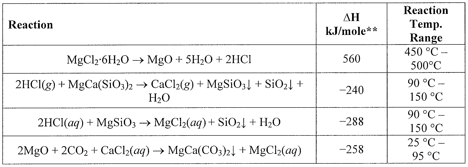


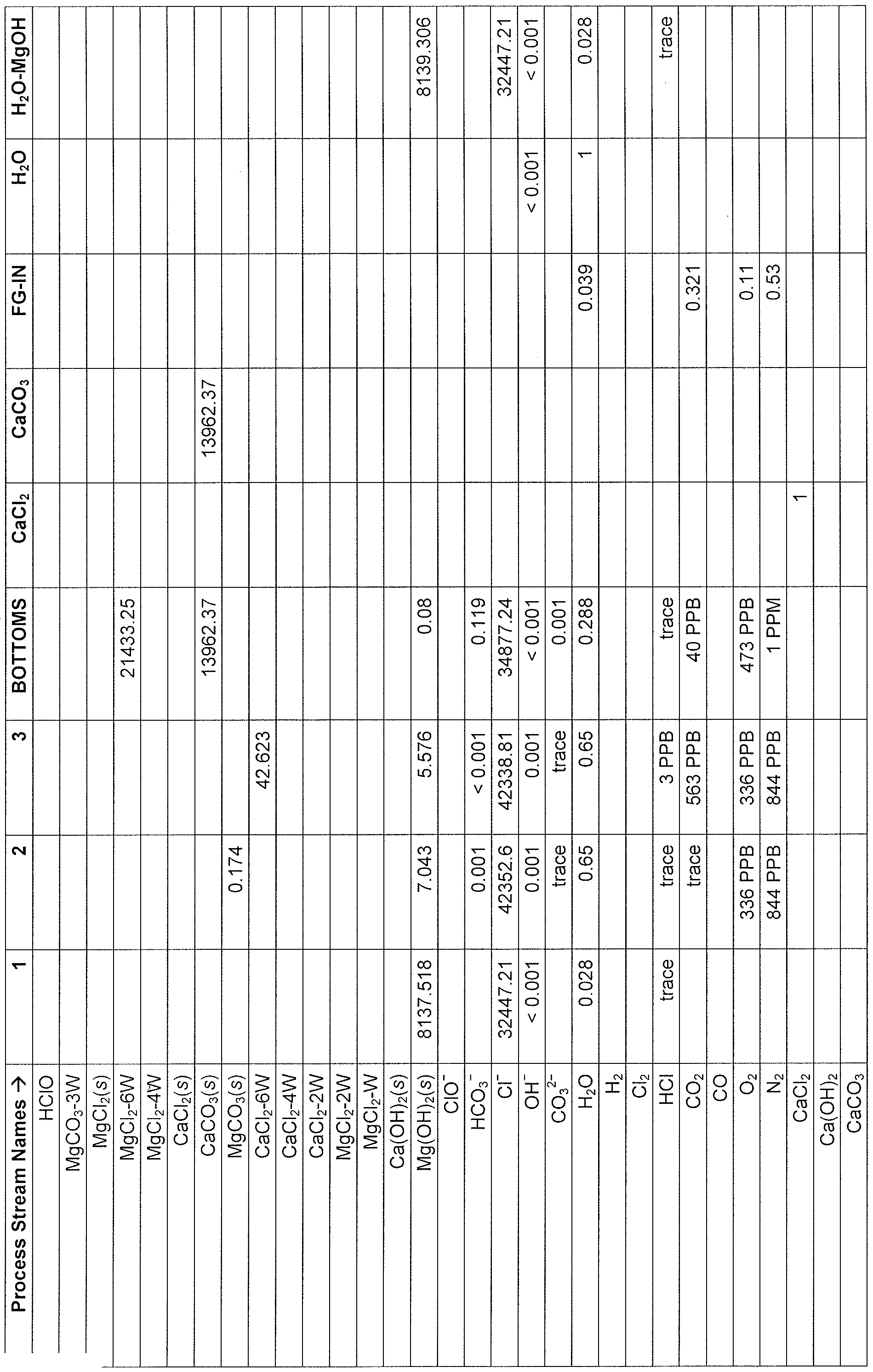


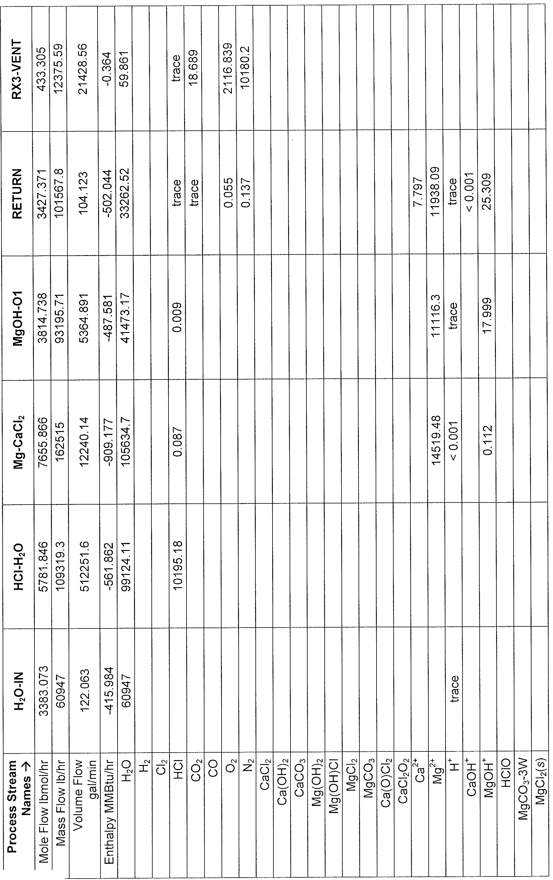


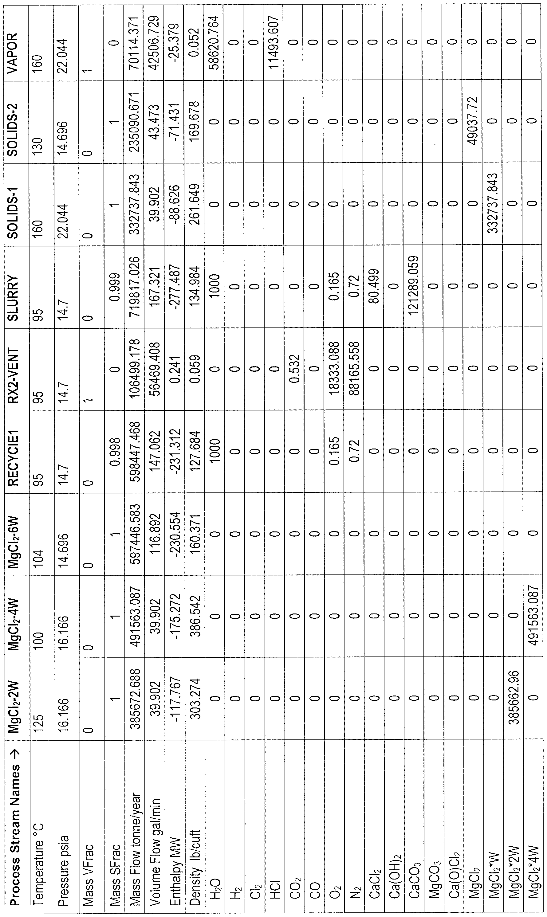


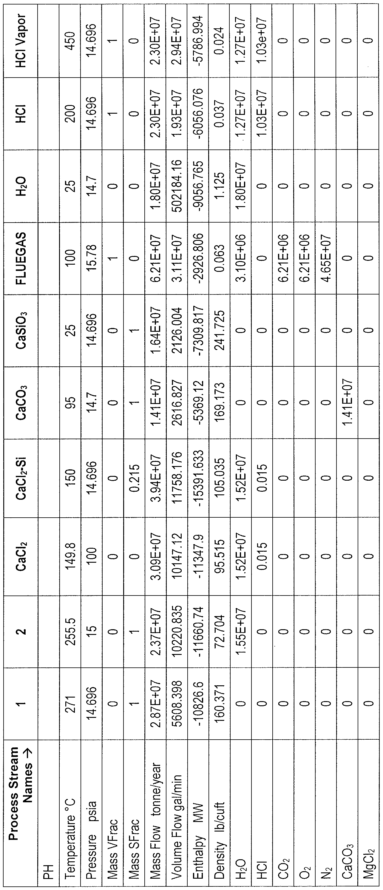


Claims
Priority Applications (17)
| Application Number | Priority Date | Filing Date | Title |
|---|---|---|---|
| SG11201404005SA SG11201404005SA (en) | 2012-01-11 | 2013-01-11 | Carbon dioxide sequestration involving two-salt-based thermolytic processes |
| AU2013203886A AU2013203886B2 (en) | 2012-01-11 | 2013-01-11 | Carbon dioxide sequestration involving two-salt-based thermolytic processes |
| NZ628133A NZ628133A (en) | 2012-01-11 | 2013-01-11 | Carbon dioxide sequestration involving two-salt-based thermolytic processes |
| CA2863326A CA2863326A1 (en) | 2012-01-11 | 2013-01-11 | Carbon dioxide sequestration involving two-salt-based thermolytic processes |
| HK15105469.4A HK1205039A1 (en) | 2012-01-11 | 2013-01-11 | Carbon dioxide sequestration involving two-salt-based thermolytic processes |
| AP2014007853A AP2014007853A0 (en) | 2012-01-11 | 2013-01-11 | Carbon dioxide sequestration involving two-salt-based thermolytic processes |
| JP2014552337A JP2015508332A (en) | 2012-01-11 | 2013-01-11 | Sequestration of carbon dioxide with pyrolysis process based on two kinds of salts |
| IN5949DEN2014 IN2014DN05949A (en) | 2012-01-11 | 2013-01-11 | |
| CN201380011318.3A CN104284707A (en) | 2012-01-11 | 2013-01-11 | Carbon dioxide sequestration involving two-salt-based thermolytic processes |
| BR112014017019A BR112014017019A8 (en) | 2012-01-11 | 2013-01-11 | carbon dioxide sequestration involving two-salt thermolytic processes |
| EP13736385.9A EP2809427A4 (en) | 2012-01-11 | 2013-01-11 | Carbon dioxide sequestration involving two-salt-based thermolytic processes |
| MX2014008491A MX2014008491A (en) | 2012-01-11 | 2013-01-11 | Carbon dioxide sequestration involving two-salt-based thermolytic processes. |
| EA201491342A EA201491342A1 (en) | 2012-01-11 | 2013-01-11 | COVER OF CARBON DIOXIDE, INCLUDING TWO-SOLE THERMOLYTIC WAYS |
| KR1020147022332A KR20140111034A (en) | 2012-01-11 | 2013-01-11 | Carbon dioxide sequestration involving two-salt-based thermolytic processes |
| HK15106677.0A HK1205976A1 (en) | 2012-01-11 | 2013-01-11 | Carbon dioxide sequestration involving two-salt-based thermolytic processes |
| IL233577A IL233577A0 (en) | 2012-01-11 | 2014-07-09 | Carbon dioxide sequestration involving two-salt-based thermolytic processes |
| PH12014501606A PH12014501606A1 (en) | 2012-01-11 | 2014-07-11 | Carbon dioxide sequestration involving two-salt-based thermolytic processes |
Applications Claiming Priority (2)
| Application Number | Priority Date | Filing Date | Title |
|---|---|---|---|
| US201261585597P | 2012-01-11 | 2012-01-11 | |
| US61/585,597 | 2012-01-11 |
Publications (1)
| Publication Number | Publication Date |
|---|---|
| WO2013106730A1 true WO2013106730A1 (en) | 2013-07-18 |
Family
ID=48781952
Family Applications (1)
| Application Number | Title | Priority Date | Filing Date |
|---|---|---|---|
| PCT/US2013/021264 Ceased WO2013106730A1 (en) | 2012-01-11 | 2013-01-11 | Carbon dioxide sequestration involving two-salt-based thermolytic processes |
Country Status (23)
| Country | Link |
|---|---|
| US (1) | US20130202516A1 (en) |
| EP (1) | EP2809427A4 (en) |
| JP (1) | JP2015508332A (en) |
| KR (1) | KR20140111034A (en) |
| CN (1) | CN104284707A (en) |
| AP (1) | AP2014007853A0 (en) |
| AR (1) | AR090051A1 (en) |
| AU (1) | AU2013203886B2 (en) |
| BR (1) | BR112014017019A8 (en) |
| CA (1) | CA2863326A1 (en) |
| CL (1) | CL2014001842A1 (en) |
| CO (1) | CO7020904A2 (en) |
| EA (1) | EA201491342A1 (en) |
| HK (2) | HK1205039A1 (en) |
| IL (1) | IL233577A0 (en) |
| IN (1) | IN2014DN05949A (en) |
| MX (1) | MX2014008491A (en) |
| NZ (1) | NZ628133A (en) |
| PE (1) | PE20142384A1 (en) |
| PH (1) | PH12014501606A1 (en) |
| SG (1) | SG11201404005SA (en) |
| TW (1) | TW201335071A (en) |
| WO (1) | WO2013106730A1 (en) |
Cited By (3)
| Publication number | Priority date | Publication date | Assignee | Title |
|---|---|---|---|---|
| WO2017113539A1 (en) * | 2015-12-29 | 2017-07-06 | 原初科技(北京)有限公司 | Carbon dioxide absorption and mineralization device and method |
| WO2019014309A1 (en) | 2017-07-13 | 2019-01-17 | Verdezyne (Abc), Llc | Biological methods for modifying cellular carbon flux |
| US10583394B2 (en) | 2015-02-23 | 2020-03-10 | Carbonfree Chemicals Holdings, Llc | Carbon dioxide sequestration with magnesium hydroxide and regeneration of magnesium hydroxide |
Families Citing this family (10)
| Publication number | Priority date | Publication date | Assignee | Title |
|---|---|---|---|---|
| CA2937108A1 (en) | 2014-01-17 | 2015-07-23 | Skyonic Corporation | Acid gas removal from a gaseous stream |
| EA201790890A1 (en) | 2014-10-21 | 2017-10-31 | Скайоник Корпорейшн | TREATMENT OF SEWAGE WATER UP TO A LEVEL SUITABLE FOR REPEATED USE IN A CO REMOVAL METHOD AND SYSTEM |
| AU2017381715B2 (en) | 2016-12-21 | 2023-11-09 | Isca Management Ltd. | Removal of greenhouse gases and heavy metals from an emission stream |
| CN107324753B (en) * | 2017-04-10 | 2020-01-17 | 南京工业大学 | A kind of carbonate cementitious material and preparation method thereof |
| CN107720800A (en) * | 2017-11-07 | 2018-02-23 | 王麒 | Recycle the method and system of carbon dioxide |
| KR102140915B1 (en) * | 2018-11-27 | 2020-08-05 | 한국에너지기술연구원 | Carbon dioxide mineralization reactor and carbon dioxide immobilization method |
| US11717802B2 (en) | 2021-03-04 | 2023-08-08 | Energy And Environmental Research Center Foundation | Methods of treating metal carbonate salts |
| US11858819B2 (en) | 2021-03-04 | 2024-01-02 | Energy And Environmental Research Center Foundation | Methods of producing a syngas composition |
| WO2023210261A1 (en) * | 2022-04-26 | 2023-11-02 | 株式会社Inpex | Processing method and processing apparatus |
| WO2025171399A1 (en) * | 2024-02-09 | 2025-08-14 | Carbonfree Chemicals Holdings, Llc | Co2 capture device using cavitation |
Citations (2)
| Publication number | Priority date | Publication date | Assignee | Title |
|---|---|---|---|---|
| US1978403A (en) * | 1932-12-31 | 1934-10-30 | Dow Chemical Co | Process of separating calcium and magnesium chlorides |
| US20120034144A1 (en) * | 2010-07-08 | 2012-02-09 | Joe David Jones | Carbon dioxide sequestration involving two-salt-based thermolytic processes |
Family Cites Families (1)
| Publication number | Priority date | Publication date | Assignee | Title |
|---|---|---|---|---|
| WO2012122496A1 (en) * | 2011-03-09 | 2012-09-13 | Skyonic Corporation | Carbon dioxide sequestration methods using group 2 silicates and chlor-alkali processes |
-
2013
- 2013-01-11 MX MX2014008491A patent/MX2014008491A/en unknown
- 2013-01-11 HK HK15105469.4A patent/HK1205039A1/en unknown
- 2013-01-11 KR KR1020147022332A patent/KR20140111034A/en not_active Withdrawn
- 2013-01-11 AR ARP130100085A patent/AR090051A1/en unknown
- 2013-01-11 IN IN5949DEN2014 patent/IN2014DN05949A/en unknown
- 2013-01-11 JP JP2014552337A patent/JP2015508332A/en not_active Withdrawn
- 2013-01-11 EP EP13736385.9A patent/EP2809427A4/en not_active Withdrawn
- 2013-01-11 NZ NZ628133A patent/NZ628133A/en not_active IP Right Cessation
- 2013-01-11 CA CA2863326A patent/CA2863326A1/en not_active Abandoned
- 2013-01-11 AP AP2014007853A patent/AP2014007853A0/en unknown
- 2013-01-11 BR BR112014017019A patent/BR112014017019A8/en not_active IP Right Cessation
- 2013-01-11 SG SG11201404005SA patent/SG11201404005SA/en unknown
- 2013-01-11 WO PCT/US2013/021264 patent/WO2013106730A1/en not_active Ceased
- 2013-01-11 US US13/739,456 patent/US20130202516A1/en not_active Abandoned
- 2013-01-11 PE PE2014001101A patent/PE20142384A1/en not_active Application Discontinuation
- 2013-01-11 TW TW102101277A patent/TW201335071A/en unknown
- 2013-01-11 AU AU2013203886A patent/AU2013203886B2/en not_active Ceased
- 2013-01-11 HK HK15106677.0A patent/HK1205976A1/en unknown
- 2013-01-11 CN CN201380011318.3A patent/CN104284707A/en active Pending
- 2013-01-11 EA EA201491342A patent/EA201491342A1/en unknown
-
2014
- 2014-07-09 IL IL233577A patent/IL233577A0/en unknown
- 2014-07-11 CL CL2014001842A patent/CL2014001842A1/en unknown
- 2014-07-11 PH PH12014501606A patent/PH12014501606A1/en unknown
- 2014-07-23 CO CO14160004A patent/CO7020904A2/en unknown
Patent Citations (2)
| Publication number | Priority date | Publication date | Assignee | Title |
|---|---|---|---|---|
| US1978403A (en) * | 1932-12-31 | 1934-10-30 | Dow Chemical Co | Process of separating calcium and magnesium chlorides |
| US20120034144A1 (en) * | 2010-07-08 | 2012-02-09 | Joe David Jones | Carbon dioxide sequestration involving two-salt-based thermolytic processes |
Non-Patent Citations (2)
| Title |
|---|
| HAYWOOD ET AL.: "Carbon dioxide sequestration as stable carbonate minerals - environmental barriers", ENVIRONMENTAL GEOLOGY, vol. 41, no. IS. 1-, 2001, pages 11 - 16, XP055159410 * |
| See also references of EP2809427A4 * |
Cited By (6)
| Publication number | Priority date | Publication date | Assignee | Title |
|---|---|---|---|---|
| US10583394B2 (en) | 2015-02-23 | 2020-03-10 | Carbonfree Chemicals Holdings, Llc | Carbon dioxide sequestration with magnesium hydroxide and regeneration of magnesium hydroxide |
| US11498029B2 (en) | 2015-02-23 | 2022-11-15 | Carbonfree Chemicals Holdings, Llc | Carbon dioxide sequestration with magnesium hydroxide and regeneration of magnesium hydroxide |
| US11772046B2 (en) | 2015-02-23 | 2023-10-03 | Carbonfree Chemicals Holdings, Llc | Carbon dioxide sequestration with magnesium hydroxide and regeneration of magnesium hydroxide |
| US12179148B2 (en) | 2015-02-23 | 2024-12-31 | Carbonfree Chemicals Holdings, Llc | Carbon dioxide sequestration with magnesium hydroxide and regeneration of magnesium hydroxide |
| WO2017113539A1 (en) * | 2015-12-29 | 2017-07-06 | 原初科技(北京)有限公司 | Carbon dioxide absorption and mineralization device and method |
| WO2019014309A1 (en) | 2017-07-13 | 2019-01-17 | Verdezyne (Abc), Llc | Biological methods for modifying cellular carbon flux |
Also Published As
| Publication number | Publication date |
|---|---|
| MX2014008491A (en) | 2015-04-16 |
| NZ628133A (en) | 2015-11-27 |
| AP2014007853A0 (en) | 2014-08-31 |
| CN104284707A (en) | 2015-01-14 |
| HK1205039A1 (en) | 2015-12-11 |
| JP2015508332A (en) | 2015-03-19 |
| IL233577A0 (en) | 2014-08-31 |
| BR112014017019A8 (en) | 2017-07-04 |
| EP2809427A4 (en) | 2015-08-26 |
| AR090051A1 (en) | 2014-10-15 |
| CL2014001842A1 (en) | 2015-05-08 |
| PE20142384A1 (en) | 2015-01-25 |
| AU2013203886A1 (en) | 2013-07-25 |
| EP2809427A1 (en) | 2014-12-10 |
| CA2863326A1 (en) | 2013-07-18 |
| AU2013203886B2 (en) | 2015-10-29 |
| BR112014017019A2 (en) | 2017-06-13 |
| CO7020904A2 (en) | 2014-08-11 |
| PH12014501606A1 (en) | 2014-10-13 |
| SG11201404005SA (en) | 2014-08-28 |
| TW201335071A (en) | 2013-09-01 |
| IN2014DN05949A (en) | 2015-06-26 |
| KR20140111034A (en) | 2014-09-17 |
| US20130202516A1 (en) | 2013-08-08 |
| HK1205976A1 (en) | 2015-12-31 |
| EA201491342A1 (en) | 2015-05-29 |
Similar Documents
| Publication | Publication Date | Title |
|---|---|---|
| US9359221B2 (en) | Carbon dioxide sequestration involving two-salt-based thermolytic processes | |
| US9339761B2 (en) | Carbon dioxide sequestration methods using group 2 silicates and chlor-alkali processes | |
| WO2013106730A1 (en) | Carbon dioxide sequestration involving two-salt-based thermolytic processes | |
| US8795508B2 (en) | Carbon dioxide sequestration through formation of group-2 carbonates and silicon dioxide | |
| CA2777893A1 (en) | Method and apparatus to sequester co2 gas | |
| KR20250056231A (en) | Passive and forced synthesis of MG(OH)2 for magnesium-based CO2 capture | |
| AU2011274391B8 (en) | Carbon dioxide sequestrations involving two-salt-based thermolytic processes | |
| HK1185302B (en) | Carbon dioxide sequestrations involving two-salt-based thermolytic processes | |
| OA16950A (en) | Carbon dioxide sequestration involving two-salt-based thermolytic processes. |
Legal Events
| Date | Code | Title | Description |
|---|---|---|---|
| WWE | Wipo information: entry into national phase |
Ref document number: 2013203886 Country of ref document: AU |
|
| 121 | Ep: the epo has been informed by wipo that ep was designated in this application |
Ref document number: 13736385 Country of ref document: EP Kind code of ref document: A1 |
|
| ENP | Entry into the national phase |
Ref document number: 2863326 Country of ref document: CA |
|
| WWE | Wipo information: entry into national phase |
Ref document number: 233577 Country of ref document: IL |
|
| ENP | Entry into the national phase |
Ref document number: 2014552337 Country of ref document: JP Kind code of ref document: A |
|
| NENP | Non-entry into the national phase |
Ref country code: DE |
|
| WWE | Wipo information: entry into national phase |
Ref document number: 2014001842 Country of ref document: CL Ref document number: 001101-2014 Country of ref document: PE Ref document number: 12014501606 Country of ref document: PH Ref document number: MX/A/2014/008491 Country of ref document: MX |
|
| WWE | Wipo information: entry into national phase |
Ref document number: 14160004 Country of ref document: CO |
|
| ENP | Entry into the national phase |
Ref document number: 13541 Country of ref document: GE Kind code of ref document: P |
|
| WWE | Wipo information: entry into national phase |
Ref document number: 201491342 Country of ref document: EA |
|
| ENP | Entry into the national phase |
Ref document number: 20147022332 Country of ref document: KR Kind code of ref document: A |
|
| WWE | Wipo information: entry into national phase |
Ref document number: A201408973 Country of ref document: UA Ref document number: 2013736385 Country of ref document: EP |
|
| REG | Reference to national code |
Ref country code: BR Ref legal event code: B01A Ref document number: 112014017019 Country of ref document: BR |
|
| ENP | Entry into the national phase |
Ref document number: 112014017019 Country of ref document: BR Kind code of ref document: A2 Effective date: 20140710 |