WO2013108311A1 - 携帯端末装置 - Google Patents
携帯端末装置 Download PDFInfo
- Publication number
- WO2013108311A1 WO2013108311A1 PCT/JP2012/006315 JP2012006315W WO2013108311A1 WO 2013108311 A1 WO2013108311 A1 WO 2013108311A1 JP 2012006315 W JP2012006315 W JP 2012006315W WO 2013108311 A1 WO2013108311 A1 WO 2013108311A1
- Authority
- WO
- WIPO (PCT)
- Prior art keywords
- housing
- terminal device
- frame member
- mobile terminal
- battery
- Prior art date
- Legal status (The legal status is an assumption and is not a legal conclusion. Google has not performed a legal analysis and makes no representation as to the accuracy of the status listed.)
- Ceased
Links
Images










Classifications
-
- H—ELECTRICITY
- H04—ELECTRIC COMMUNICATION TECHNIQUE
- H04M—TELEPHONIC COMMUNICATION
- H04M1/00—Substation equipment, e.g. for use by subscribers
- H04M1/02—Constructional features of telephone sets
- H04M1/0202—Portable telephone sets, e.g. cordless phones, mobile phones or bar type handsets
- H04M1/0249—Details of the mechanical connection between the housing parts or relating to the method of assembly
-
- G—PHYSICS
- G06—COMPUTING OR CALCULATING; COUNTING
- G06F—ELECTRIC DIGITAL DATA PROCESSING
- G06F1/00—Details not covered by groups G06F3/00 - G06F13/00 and G06F21/00
- G06F1/16—Constructional details or arrangements
- G06F1/1613—Constructional details or arrangements for portable computers
- G06F1/1633—Constructional details or arrangements of portable computers not specific to the type of enclosures covered by groups G06F1/1615 - G06F1/1626
- G06F1/1656—Details related to functional adaptations of the enclosure, e.g. to provide protection against EMI, shock, water, or to host detachable peripherals like a mouse or removable expansions units like PCMCIA cards, or to provide access to internal components for maintenance or to removable storage supports like CDs or DVDs, or to mechanically mount accessories
-
- G—PHYSICS
- G06—COMPUTING OR CALCULATING; COUNTING
- G06F—ELECTRIC DIGITAL DATA PROCESSING
- G06F1/00—Details not covered by groups G06F3/00 - G06F13/00 and G06F21/00
- G06F1/16—Constructional details or arrangements
- G06F1/1613—Constructional details or arrangements for portable computers
- G06F1/1633—Constructional details or arrangements of portable computers not specific to the type of enclosures covered by groups G06F1/1615 - G06F1/1626
- G06F1/1635—Details related to the integration of battery packs and other power supplies such as fuel cells or integrated AC adapter
-
- G—PHYSICS
- G06—COMPUTING OR CALCULATING; COUNTING
- G06F—ELECTRIC DIGITAL DATA PROCESSING
- G06F1/00—Details not covered by groups G06F3/00 - G06F13/00 and G06F21/00
- G06F1/16—Constructional details or arrangements
- G06F1/1613—Constructional details or arrangements for portable computers
- G06F1/1633—Constructional details or arrangements of portable computers not specific to the type of enclosures covered by groups G06F1/1615 - G06F1/1626
- G06F1/1637—Details related to the display arrangement, including those related to the mounting of the display in the housing
-
- H—ELECTRICITY
- H04—ELECTRIC COMMUNICATION TECHNIQUE
- H04M—TELEPHONIC COMMUNICATION
- H04M1/00—Substation equipment, e.g. for use by subscribers
- H04M1/02—Constructional features of telephone sets
- H04M1/0202—Portable telephone sets, e.g. cordless phones, mobile phones or bar type handsets
- H04M1/026—Details of the structure or mounting of specific components
- H04M1/0262—Details of the structure or mounting of specific components for a battery compartment
-
- H—ELECTRICITY
- H04—ELECTRIC COMMUNICATION TECHNIQUE
- H04M—TELEPHONIC COMMUNICATION
- H04M1/00—Substation equipment, e.g. for use by subscribers
- H04M1/02—Constructional features of telephone sets
- H04M1/0202—Portable telephone sets, e.g. cordless phones, mobile phones or bar type handsets
- H04M1/026—Details of the structure or mounting of specific components
- H04M1/0266—Details of the structure or mounting of specific components for a display module assembly
-
- H—ELECTRICITY
- H04—ELECTRIC COMMUNICATION TECHNIQUE
- H04M—TELEPHONIC COMMUNICATION
- H04M1/00—Substation equipment, e.g. for use by subscribers
- H04M1/02—Constructional features of telephone sets
- H04M1/0202—Portable telephone sets, e.g. cordless phones, mobile phones or bar type handsets
- H04M1/026—Details of the structure or mounting of specific components
- H04M1/0277—Details of the structure or mounting of specific components for a printed circuit board assembly
-
- H—ELECTRICITY
- H04—ELECTRIC COMMUNICATION TECHNIQUE
- H04M—TELEPHONIC COMMUNICATION
- H04M1/00—Substation equipment, e.g. for use by subscribers
- H04M1/02—Constructional features of telephone sets
- H04M1/18—Telephone sets specially adapted for use in ships, mines, or other places exposed to adverse environment
- H04M1/185—Improving the shock resistance of the housing, e.g. by increasing the rigidity
Definitions
- the present invention relates to a mobile terminal device, and more particularly to a mobile terminal device using a thin flat housing.
- mobile terminal devices such as mobile phones and smartphones have become widespread.
- a user often carries and uses a mobile terminal device, for example, when the user accidentally drops the mobile terminal device, a strong impact is applied to the mobile terminal device.
- Patent Document 1 discloses a technique related to a liquid crystal device that can prevent deterioration in orientation and image quality of a liquid crystal panel even when a strong impact is applied.
- a vibration-resistant shock unit having two shock absorbing spaces provided on both sides of the liquid crystal panel for preventing the shock applied to the liquid crystal device body from being transmitted to the liquid crystal panel is fixed. It is fixed to the member.
- the vibration-resistant shock unit is indirectly fixed to the first exterior member by fixing the fixing member to which the vibration-resistant impact unit is fixed to the first exterior member that forms the outer surface of the liquid crystal device main body. The strong shock applied to the main body is not transmitted to the liquid crystal panel.
- an object of the present invention is to provide a portable terminal device capable of realizing a reduction in thickness and an improvement in impact resistance.
- a mobile terminal device is fixed to the housing on a frame member to which a substrate and a battery are fixed, a housing to which the frame member is fixed, and a side to which the frame member is fixed.
- a display unit is fixed to the housing on a frame member to which a substrate and a battery are fixed, a housing to which the frame member is fixed, and a side to which the frame member is fixed.
- the present invention it is possible to provide a mobile terminal device capable of realizing a reduction in thickness and an improvement in impact resistance.
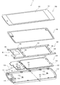
- FIG. 1 is an exploded perspective view illustrating an example of a mobile terminal device according to a first exemplary embodiment
- FIG. 3 is an exploded perspective view showing an example of a display unit of the mobile terminal device according to the first exemplary embodiment.
- FIG. 3 is a bottom view of the display unit of the mobile terminal device according to the first exemplary embodiment;
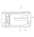
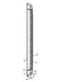
- FIG. 4 is a cross-sectional view taken along IV-IV of the mobile terminal device shown in FIG. 1. It is a perspective view which shows an example of the battery with which the portable terminal device concerning Embodiment 1 is provided.
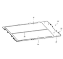
- FIG. 2 is a perspective view of the back surface of the mobile terminal device according to the first exemplary embodiment;
- FIG. 5 is an exploded perspective view showing another example of the mobile terminal device according to the first exemplary embodiment.
- FIG. 1 is an exploded perspective view illustrating an example of a mobile terminal device according to a first exemplary embodiment
- FIG. 3 is an exploded perspective view showing an example of a display unit of the mobile terminal device according to the first
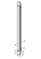
- FIG. 8 is a cross-sectional view taken along line VIII-VIII of the mobile terminal device shown in FIG.
- FIG. 6 is an exploded perspective view illustrating an example of a mobile terminal device according to a second exemplary embodiment.
- FIG. 6 is an exploded perspective view illustrating an example of a display unit of a mobile terminal device according to a second exemplary embodiment.
- FIG. 6 is a bottom view of a display unit of a mobile terminal device according to a second exemplary embodiment.
- FIG. 10 is a cross-sectional view taken along the line XII-XII of the mobile terminal device shown in FIG. It is a perspective view which shows an example of the battery with which the portable terminal device concerning Embodiment 2 is provided.
- FIG. 10 is an exploded perspective view showing another example of the mobile terminal device according to the second exemplary embodiment.
- FIG. 16 is a cross-sectional view taken along the line XVI-XVI of the mobile terminal device shown in FIG.
- FIG. 1 is an exploded perspective view showing an example of a mobile terminal device according to the present embodiment.
- 4 is a cross-sectional view taken along IV-IV of the mobile terminal device 1 shown in FIG.
- the battery 20, the substrate 30, and the frame member 40 are accommodated in a space formed by joining the housing 10 and the display unit 50.
- the mobile terminal device 1 according to the present embodiment is, for example, a smartphone, a tablet-type mobile terminal device, a mobile phone, a game machine, an electronic book terminal, or the like.
- the battery 20 includes a battery main body 21 and a fixing member 22 for fixing the battery main body 21 to the frame member 40.
- the battery body 21 is a lithium ion secondary battery, for example.
- the fixing member 22 is provided around the battery main body 21.
- a plurality of mounting holes 23 for fixing the battery 20 to the frame member 40 using screws or the like are formed in the fixing member 22 at positions corresponding to the mounting holes 44 of the frame member 40. In the example shown in FIG. 1, two attachment holes 23 are formed at both ends of the battery 20 in the longitudinal direction.
- the fixing member 22 may be a member that can fix the battery main body 21 to the frame member 40, and may be a member that is integrally formed so as to surround the battery main body 21. A plurality of members may be provided separately at a plurality of surrounding locations.
- the fixing member 22 can be formed using a resin, for example. Further, the battery body 21 and the fixing member 22 may be integrally formed. That is, when the battery main body 21 is formed, the attachment holes 23 may be formed around the battery main body 21.
- the battery 20 may be configured using a plurality of cells 25 and 26, as in the battery 20 ′ shown in FIG.
- the strength in the longitudinal direction of the battery can be improved. That is, by setting the boundary between the cells 25 and 26 as the longitudinal direction of the housing 10, the strength in the longitudinal direction of the battery is improved as compared with the case where the cell boundary is provided in a direction perpendicular to the longitudinal direction of the housing 10. be able to.
- the strength in the longitudinal direction of the battery can be improved by providing the beam 28 at the central portion of the fixing member 22 for fixing the battery body (cells 25, 26) to the frame member 40.
- the substrate 30 is provided with circuit elements 31 and 32.
- the circuit elements 31 and 32 are, for example, an integrated circuit device such as a processor, a memory, and a communication module for driving a mobile terminal device, an image sensor for a camera, and the like.
- a plurality of attachment holes 33 for fixing the substrate 30 to the frame member 40 using screws or the like are formed in the substrate 30 at positions corresponding to the attachment holes 45 of the frame member 40. In the example shown in FIG. 1, three attachment holes 33 for attaching the substrate 30 to the frame member 40 are formed.
- the frame member 40 is a member for holding the battery 20 and the substrate 30. Since the frame member 40 requires a certain level of strength, it is preferably formed of a metal material. Examples of the material used for the frame member 40 include magnesium alloy, aluminum, and stainless steel. In view of weight reduction of the mobile terminal device 1, it is preferable to use a magnesium alloy. Further, the frame member 40 may be formed using a resin material as long as the strength can be ensured.
- the frame member 40 has an opening 41 at a position corresponding to the position where the battery 20 is attached. That is, the frame member 40 has an opening (first opening) 41 at a position facing the upper surface (first surface) of the battery 20.
- the opening 41 By providing the opening 41 in this manner, as shown in the cross-sectional view of FIG. 4, a part of the battery 40 can be provided inside the frame member 40, and the space inside the housing can be effectively used. it can.
- the battery 20 may be fixed so that the upper surface of the battery 20 protrudes from the upper surface of the frame member 40, and the battery 20 is mounted so that the upper surface of the battery 20 and the upper surface of the frame member 40 are flush with each other. It may be fixed.
- the interference between the display unit 50 (that is, the touch panel 51 and the display panel 52) and the battery 20 is reduced, and the thickness can be reduced. Further, when the upper surface of the battery 20 and the upper surface of the frame member 40 are the same surface, and the same surface and the display unit 50 (that is, the touch panel 51 or the display panel 52) are in close contact with each other, the thickness is further reduced. And the strength of the entire terminal can be improved.
- the frame member 40 is formed with a plurality of mounting holes 44 for fixing the battery 20 to the frame member 40 using screws or the like at positions corresponding to the mounting holes 23 of the battery 20.
- four attachment holes 44 for attaching the battery 20 to the frame member 40 are formed.
- the battery 40 is fixed to the frame member 40 from the side where the housing 10 is provided using screws or the like.
- the frame member 40 has openings (second openings) 42 and 43 at positions corresponding to the circuit elements 31 and 32 provided on the substrate 30.
- the frame member 40 and the circuit elements 31 and 32 interfere with each other even when the circuit elements 31 and 32 provided on the substrate 30 are high. Can be suppressed.
- the frame member 40 is formed with a plurality of attachment holes 45 for fixing the substrate 30 to the frame member 40 using screws or the like at positions corresponding to the attachment holes 33 of the substrate 30.
- three attachment holes 45 for attaching the substrate 30 to the frame member 40 are formed.
- the substrate 30 is fixed to the frame member 40 from the side where the housing 10 is provided using screws or the like.
- the frame member 40 has a plurality of mounting holes 46 for fixing the frame member 40 to the housing 10 with screws or the like at positions corresponding to the fixing portion 11 of the housing 10.
- ten attachment holes 46 are provided in the outer peripheral portion of the frame member 40.
- the housing 10 is configured to accommodate the battery 20, the substrate 30, and the frame member 40 inside the housing 10.
- the housing 10 is provided with a camera hole 15.
- a plurality of fixing portions 11 for fixing the frame member 40 are provided on the inner wall of the housing 10.
- the fixing portion 11 is provided at a location corresponding to the fixing position (attachment hole 46) of the frame member 40 so as to protrude inward from the outer peripheral portion.
- a mounting hole 12 is formed in each fixing portion 11. In the example shown in FIG. 1, ten fixing portions 11 are provided in the housing 10.
- a fixing surface 13 for fixing the display unit 50 is provided on the outer peripheral portion of the housing 10.
- the fixing portion 11 is provided at a position inside the outer peripheral portion of the housing 10 and lower than the fixing surface 13.
- the frame member 40 is supported on the upper surface of the fixing portion 11 of the housing 10, and is fixed to the fixing portion 11 from the display portion 50 side using screws 48.
- the display unit 50 is fixed to the fixed surface 13 of the housing 10.
- the display unit 50 can be fixed to the fixing surface 13 of the housing 10 using an adhesive.
- the housing 10 is configured to include a carbon composite material (carbon fiber reinforced plastic (CFRP: Carbon Fiber Reinforced Plastics)).
- CFRP Carbon Fiber Reinforced Plastics
- the carbon composite material is a composite material containing 50% by volume or more of carbon and containing an inorganic binder such as silica and alumina, a fiber, and the like. Carbon composite material has both high strength and lightness. Carbon composite materials have higher thermal conductivity than resin materials (plastic materials).
- the case 10 of the portable terminal device has a portion formed using a carbon composite material and a portion formed using a resin material.
- the back surface of the housing 10 may be formed of a carbon composite material, and the periphery (portion having a curvature) of the housing 10 may be formed using a resin material (see the periphery 18 in FIG. 6).
- the housing 10 is easily processed by forming the portion having a curvature using a resin material.
- the housing 10 having the carbon composite material and the resin material can be formed, for example, by placing the carbon composite material at a predetermined location on the mold of the housing 10 and performing injection molding.
- the carbon composite material includes carbon fiber.
- Carbon fiber has the properties of high thermal conductivity and high strength along the direction of the carbon fiber. Therefore, the heat generated from the battery 20 and the substrate 30 can be diffused in the longitudinal direction of the housing 10 by providing the carbon fiber on the back surface of the housing 10 in the longitudinal direction of the housing 10. . That is, the heat dissipation effect can be improved by diffusing heat in the longitudinal direction with a large area. Further, the temperature of the housing 10 can be made uniform. Furthermore, when the mobile terminal device is dropped, a large impact is applied in the longitudinal direction of the mobile terminal device, but the strength in the longitudinal direction of the housing 10 can be improved by aligning the carbon fibers in the longitudinal direction. It is possible to improve resistance to impact at times.
- carbon fibers may be provided in a direction intersecting the longitudinal direction of the housing 10 (typically, an orthogonal direction). At this time, for the above reason, it is preferable that the amount of carbon fiber provided in the longitudinal direction of the housing 10 is larger than the amount of carbon fiber provided in the direction intersecting with the longitudinal direction of the housing 10. . Note that the amount of carbon fiber provided in the longitudinal direction of the housing 10 and the amount of carbon fiber provided in the direction intersecting the longitudinal direction of the housing 10 take into account the thermal diffusion and strength of the housing 10. Can be changed as appropriate.
- a carbon fiber layer in which the direction of the carbon fibers is oriented in the longitudinal direction of the casing 10 and a direction intersecting the longitudinal direction of the casing 10 You may laminate
- the user by setting the direction of the carbon fiber of the carbon fiber layer arranged on the outermost side (side touching the user's hand) of the housing 10 among the plurality of carbon fiber layers as the longitudinal direction of the housing 10, the user The heat diffusion on the outside of the casing 10 that touches the hand can be promoted. Thereby, when a user picks up a portable terminal device, it can be made hard to feel heat.
- the carbon fiber direction of the carbon fiber layer disposed on the innermost side of the housing 10 among the plurality of carbon fiber layers may be the longitudinal direction of the housing 10.
- the thermal conductivity in the fiber direction of the carbon fibers is about 20 to 30 times the thermal conductivity in the lamination direction of the carbon fibers. Therefore, by doing in this way, the heat generated from the battery 20 and the board 30 provided inside the housing 10 is diffused in the longitudinal direction of the housing 10 before diffusing to the outside of the housing 10. Can do.
- FIG. 6 is a rear perspective view of the mobile terminal device 1 according to the present embodiment. As shown in FIG. 6, the portions 10 and 17 where the antenna is provided in the housing 10 are formed using an insulating material such as a resin material, thereby suppressing the radio waves received by the antenna from being shielded. can do.
- a space can be provided at the longitudinal end in the casing, and an impact at the longitudinal end is achieved. Can be absorbed.
- impact absorption at the longitudinal end can be improved by forming the longitudinal end using a resin material that is softer than the carbon composite material.
- the longitudinal end portion using a resin material, and further forming the longitudinal end portion of the mobile terminal device so as to have a curvature, the impact received by the mobile terminal device at the time of dropping is reduced using the resin material.
- the vertex of the portion having the curvature is a portion that easily collides when dropped, it is preferable to form the casing using the resin material so as to include the vertex of the portion having the curvature.
- FIG. 2 is an exploded perspective view showing an example of the display unit 50 of the mobile terminal device 1 according to the present embodiment.
- the display unit 50 includes a display panel 52, a bezel 53 provided so as to surround the display panel 52, and a touch panel 51 provided on the surface side of the display panel 52.
- a panel made of glass or plastic that does not have a touch panel function may be provided on the surface side of the display panel 52 instead of the touch panel 51.
- the touch panel 51 includes a panel 61, an electrode portion 62 provided on the surface of the panel 61, and a wiring 63. Since the touch panel 51 detects the position touched by the user's finger using the capacitance, the detection signal is weak. Therefore, it is preferable that the portion where the wiring 63 of the touch panel 51 is taken out is arranged so as to overlap the substrate 30 in a direction perpendicular to the main surface (front surface) of the touch panel 51. By arranging the touch panel 51 and the substrate 30 in this manner, the length of the wiring 63 of the touch panel 51 can be shortened, and noise can be prevented from being mixed into the detection signal.
- the display panel 52 is, for example, a liquid crystal panel or an organic EL (Electro Luminescence) panel.
- a flexible cable 72 for supplying an image signal or the like to the display panel main body 71 is connected to the display panel main body 71 at an end 73 of the display panel main body 71.
- the display panel main body 71 is held by a bezel 53.
- the bezel 53 has a side wall 81 that covers the side surface of the display panel body 71 and a bottom surface 82 that covers a part of the back surface of the display panel body 71.
- An opening 83 is formed in a part of the bottom surface of the bezel 53 for weight reduction.
- the bezel 53 Since the bezel 53 needs a certain level of strength, it is preferable to form it using a metal material such as stainless steel.
- the bezel 53 is formed so that the thickness of a portion 84 corresponding to a portion (end portion 73) where the flexible cable 72 is connected to the display panel main body 71 is thin. Thereby, it can suppress that the bezel 53 and the flexible cable 72 interfere, and the thickness including the display panel 52 and the bezel 53 can be made thin.
- FIG. 3 is a bottom view of the display unit 50 of the mobile terminal device 1 according to the present embodiment.
- a display panel 52 and a bezel 53 that holds the display panel 52 are provided inside the touch panel 51.
- the size of the touch panel 51 corresponds to the size of the housing 10, and the outer peripheral portion of the touch panel 51 is fixed to the fixed surface 13 provided on the outer peripheral portion of the housing 10.
- FIG. 7 is an exploded perspective view showing another example of the portable terminal device according to the present embodiment.
- 8 is a cross-sectional view of the mobile terminal device shown in FIG. 7 taken along line VIII-VIII.
- the spacer 90 is provided between the fixing surface 13 of the housing 10 and the touch panel 51. .
- the spacer 90 is provided so as to cover the fixed surface 13 of the housing 10. At this time, as shown in the cross-sectional view of FIG.
- the spacer 90 covers the outer peripheral side surface of the touch panel 51, and the step 18 is provided on the fixed surface 13 of the housing 10, so Even when stress is applied, the touch panel 51 can be prevented from being displaced from the housing 10. In addition, by providing the spacer 90, positioning when fixing the touch panel 51 to the fixing surface 13 of the housing 10 can be facilitated.
- the mobile terminal device includes the frame member 40 to which the battery 20 and the substrate 30 are fixed, the casing 10 to which the frame member 40 is fixed and including the carbon composite material, and the frame. And at least a display unit 50 fixed to the housing 10 on the side on which the member 40 is fixed.
- the housing 10 is configured to include a carbon composite material that is stronger than resin.
- the frame member 40 to which the battery 20 and the substrate 30 are fixed is fixed to the housing 10. Therefore, the plastic deformation of the frame member 40 can be suppressed by the restoring force of the strong casing 10.
- the rigidity of the mobile terminal device can be ensured at a portion where the housing 10 and the frame member 40 are integrated. Therefore, the strength of the mobile terminal device can be maintained even when the housing 10 is thinned.
- substrate 30 are being fixed to the housing
- an impact applied to the housing 10 when the mobile terminal device is dropped is not directly transmitted to the battery 20 or the substrate 30, but is transmitted from the housing 10 to the frame member 40, and then the frame member. Since the electric power is transmitted from the battery 40 to the battery 20 and the substrate 30, the impact transmitted to the battery 20 and the substrate 30 can be reduced.
- the display unit 50 is fixed to the fixing surface 13 of the housing 10, and the frame member 40 is It is fixed to the fixing part 11. That is, the display unit 50 and the frame member 40 are independently fixed at different locations of the housing 10. Therefore, a space can be provided between the periphery of the bezel 53 and the frame member 40 (see FIGS. 4 and 8).
- the battery 20, the substrate 30, and the frame member 40 can display the display unit. The impact transmitted to 50 can be reduced.
- the invention according to this embodiment can provide a mobile terminal device capable of realizing a reduction in thickness and an improvement in impact resistance.
- FIG. 9 is an exploded perspective view showing an example of the mobile terminal device according to the present embodiment.
- 12 is a cross-sectional view taken along the line XII-XII of the mobile terminal device 2 shown in FIG.
- the battery 120, the substrate 130, and the frame member 140 are accommodated in a space formed by joining the housing 110 and the display unit 150.
- the mobile terminal device 2 according to the present embodiment is, for example, a smartphone, a tablet-type mobile terminal device, a mobile phone, a game machine, an electronic book terminal, or the like.
- the battery 120 includes a battery main body 121 and a fixing member 122 for fixing the battery main body 121 to the frame member 140.
- the battery body 121 is, for example, a lithium ion secondary battery.
- the fixing member 122 is provided around the battery main body 121.
- a plurality of mounting holes 123 for fixing the battery 120 to the frame member 140 using screws or the like are formed in the fixing member 122 at positions corresponding to the mounting holes 144 of the frame member 140. In the example shown in FIG. 9, two attachment holes 123 are formed at both ends in the longitudinal direction of the battery 120.
- the fixing member 122 only needs to be a member that can fix the battery main body 121 to the frame member 140.
- the fixing member 122 may be a member that is integrally formed so as to surround the battery main body 121.
- a plurality of members may be provided separately at a plurality of surrounding locations.
- the fixing member 122 can be formed using a resin, for example.
- the battery main body 121 and the fixing member 122 may be integrally formed. That is, when the battery main body 121 is formed, the attachment holes 123 may be formed around the battery main body 121.
- the battery 120 may be configured by using a plurality of cells 125 and 126 as in the battery 120 ′ shown in FIG.
- the strength in the longitudinal direction of the battery can be improved. That is, by setting the boundary between the cells 125 and 126 as the longitudinal direction of the housing 110, the strength in the longitudinal direction of the battery is improved as compared with the case where the cell boundary is provided in a direction perpendicular to the longitudinal direction of the housing 110. be able to.
- the beam 128 at the central portion of the fixing member 122 for fixing the battery body (cells 125 and 126) to the frame member 140, the strength in the longitudinal direction of the battery can be improved.
- the substrate 130 is provided with circuit elements 131 and 132.
- the circuit elements 131 and 132 are, for example, an integrated circuit device such as a processor, a memory, and a communication module for driving the mobile terminal device, an image sensor for a camera, and the like.
- a plurality of attachment holes 133 for fixing the substrate 130 to the frame member 140 using screws or the like are formed in the substrate 130 at positions corresponding to the attachment holes 145 of the frame member 140. In the example shown in FIG. 9, three attachment holes 133 for attaching the substrate 130 to the frame member 140 are formed.
- the frame member 140 is a member for holding the battery 120 and the substrate 130. Since the frame member 140 requires a certain level of strength, it is preferably formed of a metal material. Examples of the material used for the frame member 140 include magnesium alloy, aluminum, and stainless steel. In view of reducing the weight of the mobile terminal device 2, it is preferable to use a magnesium alloy. Further, the frame member 140 may be formed using a resin material as long as strength can be ensured.
- the frame member 140 has an opening 141 at a position corresponding to a position where the battery 120 is attached. That is, the frame member 140 has an opening (first opening) 141 at a position facing the upper surface (first surface) of the battery 120.
- the opening 141 By providing the opening 141 in this manner, as shown in the cross-sectional view of FIG. 12, a part of the battery 140 can be provided inside the frame member 140, and the space inside the housing can be effectively used. it can.
- the battery 120 may be fixed so that the upper surface of the battery 120 protrudes from the upper surface of the frame member 140, and the battery 120 is mounted so that the upper surface of the battery 120 and the upper surface of the frame member 140 are flush with each other. It may be fixed.
- the interference between the display unit 150 (that is, the touch panel 151 and the display panel 152) and the battery 120 is reduced, and the thickness can be reduced. Further, when the upper surface of the battery 120 and the upper surface of the frame member 140 are the same surface, and the same surface and the display unit 150 (that is, the touch panel 151 or the display panel 152) are in close contact with each other, the thickness is further reduced. And the strength of the entire terminal can be improved.
- the frame member 140 has a plurality of attachment holes 144 for fixing the battery 120 to the frame member 140 using screws or the like at positions corresponding to the attachment holes 123 of the battery 120.
- four attachment holes 144 for attaching the battery 120 to the frame member 140 are formed.
- the battery 140 is fixed to the frame member 140 from the side where the housing 110 is provided using screws or the like.
- the frame member 140 has openings (second openings) 142 and 143 at positions corresponding to the circuit elements 131 and 132 provided on the substrate 130.
- second openings second openings
- the frame member 140 and the circuit elements 131 and 132 interfere with each other even when the circuit elements 131 and 132 provided on the substrate 130 are high. Can be suppressed.
- the frame member 140 has a plurality of attachment holes 145 for fixing the substrate 130 to the frame member 140 with screws or the like at positions corresponding to the attachment holes 133 of the substrate 130.
- three attachment holes 145 for attaching the substrate 130 to the frame member 140 are formed.
- the substrate 130 is fixed to the frame member 140 from the side where the housing 110 is provided using screws or the like.
- the frame member 140 has a plurality of mounting holes 146 for fixing the frame member 140 to the housing 110 using screws or the like at positions corresponding to the fixing portion 11 of the housing 10. In the example shown in FIG. 9, a total of twelve attachment holes 146 are provided in the frame member 140.
- the housing 110 is configured to accommodate the battery 120, the substrate 130, and the frame member 140 inside the housing 110.
- the housing 110 is provided with a camera hole 115.
- a plurality of fixing portions 111 for fixing the frame member 140 are provided on the inner wall of the housing 110.
- the fixing portion 111 is provided at a position corresponding to the fixing position (attachment hole 146) of the frame member 140 so as to protrude inward from the outer peripheral portion.
- a fixing portion 114 for fixing the frame member 140 is also provided inside the housing 110.
- a mounting hole 112 is formed in each of the fixing portions 111 and 114. In the example shown in FIG. 9, twelve fixing portions 111 and 114 are provided in the housing 110.
- a fixing surface 113 for fixing the display unit 150 is provided on the outer periphery of the housing 110.
- the fixing portion 111 is provided at a position inside the outer peripheral portion of the housing 110 and lower than the fixing surface 113.
- the frame member 140 is supported on the upper surface of the fixing unit 111 of the housing 110 and is fixed to the fixing unit 111 from the display unit 150 side using screws 148.
- the display unit 150 is fixed to the fixed surface 113 of the housing 110.
- the display unit 150 can be fixed to the fixing surface 113 of the housing 110 using an adhesive.
- the attachment position of the frame member 140 can be separated from the display portion 150. For example, when the mobile terminal device is dropped, the display portion is removed from the battery. The impact transmitted to 150 can be reduced.
- the housing 110 includes a carbon composite material (carbon fiber reinforced plastic (CFRP: Carbon Fiber Reinforced Plastics)).
- CFRP Carbon Fiber Reinforced Plastics
- the carbon composite material is a composite material containing 50% by volume or more of carbon and containing an inorganic binder such as silica and alumina, a fiber, and the like. Carbon composite material has both high strength and lightness. Carbon composite materials have higher thermal conductivity than resin materials (plastic materials).
- the case 110 of the portable terminal device has a portion formed using a carbon composite material and a portion formed using a resin material.
- the back surface of the housing 110 may be formed of a carbon composite material, and the periphery (portion having a curvature) of the housing 110 may be formed using a resin material (see the periphery 118 in FIG. 14).
- the housing 110 is easily processed by forming the portion having a curvature using a resin material.
- the housing 110 having the carbon composite material and the resin material can be formed, for example, by placing the carbon composite material at a predetermined location on the mold of the housing 110 and performing injection molding.
- the carbon composite material includes carbon fiber.
- Carbon fiber has the properties of high thermal conductivity and high strength along the direction of the carbon fiber. Therefore, the heat generated from the battery 120 or the substrate 130 can be diffused in the longitudinal direction of the housing 110 by providing the carbon fiber on the back surface of the housing 110 so as to be in the longitudinal direction of the housing 110. . That is, the heat dissipation effect can be improved by diffusing heat in the longitudinal direction with a large area. Further, the temperature of the housing 110 can be made uniform. Furthermore, when the mobile terminal device is dropped, a large impact is applied in the longitudinal direction of the mobile terminal device, but the strength in the longitudinal direction of the housing 110 can be improved by aligning the carbon fibers in the longitudinal direction, and the mobile terminal device is dropped. It is possible to improve resistance to impact at times.
- carbon fibers may be provided in a direction (typically, an orthogonal direction) that intersects the longitudinal direction of the housing 110. At this time, for the reason described above, it is preferable that the amount of carbon fiber provided in the longitudinal direction of the housing 110 is larger than the amount of carbon fiber provided in the direction intersecting the longitudinal direction of the housing 110. . Note that the amount of carbon fiber provided in the longitudinal direction of the housing 110 and the amount of carbon fiber provided in a direction intersecting the longitudinal direction of the housing 110 take into account the thermal diffusion and strength of the housing 110. Can be changed as appropriate.
- the carbon fiber direction of the carbon fiber layer disposed on the innermost side of the housing 110 among the plurality of carbon fiber layers may be the longitudinal direction of the housing 110.
- the thermal conductivity in the fiber direction of the carbon fibers is about 20 to 30 times the thermal conductivity in the lamination direction of the carbon fibers. Therefore, by doing in this way, the heat generated from the battery 120 and the board 130 provided in the housing 110 is diffused in the longitudinal direction of the housing 110 before diffusing to the outside of the housing 110. Can do.
- FIG. 14 is a rear perspective view of the portable terminal device 2 according to the present embodiment. As shown in FIG. 14, the portions 116 and 117 where the antenna is provided in the housing 110 are formed using an insulating material such as a resin material, thereby suppressing radio waves received by the antenna from being shielded. can do.
- a space can be provided at the longitudinal end in the casing, and an impact at the longitudinal end is achieved. Can be absorbed.
- impact absorption at the longitudinal end can be improved by forming the longitudinal end using a resin material that is softer than the carbon composite material.
- the longitudinal end portion using a resin material, and further forming the longitudinal end portion of the mobile terminal device so as to have a curvature, the impact received by the mobile terminal device at the time of dropping is reduced using the resin material.
- the vertex of the portion having the curvature is a portion that easily collides when dropped, it is preferable to form the casing using the resin material so as to include the vertex of the portion having the curvature.
- FIG. 10 is an exploded perspective view showing an example of the display unit 150 of the mobile terminal device 2 according to the present embodiment.
- the display unit 150 includes a display panel 152, a bezel 153 provided so as to surround the display panel 152, and a touch panel 151 provided on the surface side of the display panel 152.
- a panel formed of glass or plastic that does not have a touch panel function may be provided on the surface side of the display panel 152 instead of the touch panel 151.
- the touch panel 151 includes a panel 161, an electrode portion 162 provided on the surface of the panel 161, and a wiring 163. Since the touch panel 151 detects a position touched by a user's finger using capacitance, the detection signal is weak. Therefore, it is preferable that a portion where the wiring 163 of the touch panel 151 is taken out is arranged so as to overlap the substrate 130 in a direction perpendicular to the main surface (front surface) of the touch panel 151. By arranging the touch panel 151 and the substrate 130 in this manner, the length of the wiring 163 of the touch panel 151 can be shortened, and noise can be prevented from being mixed into the detection signal.
- the display panel 152 is, for example, a liquid crystal panel or an organic EL panel.
- Flexible cables 172 and 174 for supplying image signals and the like to the display panel body 171 are connected to the display panel body 171 at end portions 173 and 175 of the display panel body 171.
- the display panel main body 171 is held by a bezel 153.
- the bezel 153 has a side wall 181 that covers the side surface of the display panel body 171 and a bottom surface 182 that covers a part of the back surface of the display panel body 171.
- An opening 183 is formed in a part of the bottom surface of the bezel 153 to reduce the weight.
- the bezel 153 is provided to prevent the display panel body 171 from being distorted by its own weight when the size of the display panel body 171 is large. For example, if the size of the display panel main body 171 is about 4 inches, the display panel main body 171 is less distorted by its own weight. However, when the size of the display panel main body 171 is 7 inches or more, distortion due to its own weight increases, and the bezel 153 is required. The reason for leaving the corners of the bezel 153 is to ensure the strength of the bezel 153.
- the bezel 153 is preferably formed using a metal material such as stainless steel because a certain level of strength is required.
- the bezel 153 is formed so that the thickness of a portion 184 corresponding to a portion (end portions 173 and 175) where the flexible cables 172 and 174 are connected to the display panel main body 171 is reduced. Accordingly, interference between the bezel 153 and the flexible cables 172 and 175 can be suppressed, and the thickness including the display panel 152 and the bezel 153 can be reduced.
- FIG. 11 is a bottom view of the display unit 150 of the mobile terminal device 2 according to the present embodiment.
- FIG. 11 is a diagram for comparing the sizes of the touch panel 151, the display panel 152, and the frame member 140 (the bezel 153 is omitted).
- the frame member 140 is provided inside the touch panel 151
- the display panel 152 is further provided inside the frame member 140.
- the size of the touch panel 151 corresponds to the size of the housing 110, and the outer peripheral portion of the touch panel 151 is fixed to a fixing surface 113 provided on the outer peripheral portion of the housing 110.
- FIG. 15 is an exploded perspective view showing another example of the portable terminal device according to the present embodiment.
- 16 is a cross-sectional view taken along the line XVI-XVI of the mobile terminal device shown in FIG.
- the spacer 190 is provided between the fixing surface 113 of the casing 110 and the touch panel 151.
- the spacer 190 is provided so as to cover the fixing surface 113 of the housing 110. At this time, as shown in the cross-sectional view of FIG.
- the spacer 190 covers the outer peripheral side surface of the touch panel 151, and a step 118 is provided on the fixed surface 113 of the housing 110, so that the touch panel 151 has an in-plane direction. Even when stress is applied, the touch panel 151 can be prevented from being displaced from the housing 110. In addition, by providing the spacer 190, positioning when the touch panel 151 is fixed to the fixing surface 113 of the housing 110 can be facilitated.
- the mobile terminal device includes the frame member 140 to which the battery 120 and the substrate 130 are fixed, the casing 110 to which the frame member 140 is fixed and including the carbon composite material, and the frame. And a display unit 150 fixed to the housing 110 on the side where the member 140 is fixed.
- the housing 110 is configured to include a carbon composite material that is stronger than the resin.
- the frame member 140 to which the battery 120 and the substrate 130 are fixed is fixed to the housing 110. Therefore, plastic deformation of the frame member 140 can be suppressed by the restoring force of the strong casing 110.
- the rigidity of the mobile terminal device can be ensured at a portion where the casing 110 and the frame member 140 are integrated. Therefore, the strength of the mobile terminal device can be maintained even when the housing 110 is thinned.
- substrate 30 are being fixed to the housing
- the impact applied to the casing 110 when the mobile terminal device is dropped is not transmitted directly to the battery 120 or the substrate 130 but is transmitted from the casing 110 to the frame member 140, and then the frame member 140 is transmitted to the battery 120 and the substrate 130, the impact transmitted to the battery 120 and the substrate 130 can be reduced.
- the display unit 150 is fixed to the fixing surface 113 of the casing 110, and the frame member 140 is It is fixed to the fixing part 111. That is, the display unit 150 and the frame member 140 are fixed independently at different locations of the housing 110. Therefore, a space can be provided between the periphery of the bezel 153 and the frame member 140 (see FIGS. 12 and 16).
- the battery 120, the substrate 130, and the frame member 140 are connected to the display unit. The impact transmitted to 50 can be reduced.
- the invention according to this embodiment can provide a mobile terminal device capable of realizing a reduction in thickness and an improvement in impact resistance.
Landscapes
- Engineering & Computer Science (AREA)
- Computer Hardware Design (AREA)
- Theoretical Computer Science (AREA)
- General Engineering & Computer Science (AREA)
- Human Computer Interaction (AREA)
- Physics & Mathematics (AREA)
- General Physics & Mathematics (AREA)
- Signal Processing (AREA)
- Power Engineering (AREA)
- Telephone Set Structure (AREA)
- Casings For Electric Apparatus (AREA)
- Devices For Indicating Variable Information By Combining Individual Elements (AREA)
Description
以下、図面を参照して本発明の実施の形態について説明する。
図1は、本実施の形態にかかる携帯端末装置の一例を示す分解斜視図である。図4は、図1に示す携帯端末装置1のIV-IVにおける断面図である。本実施の形態にかかる携帯端末装置1では、筐体10と表示部50とを接合することで形成される空間に、バッテリ20、基板30、およびフレーム部材40が収容される。本実施の形態にかかる携帯端末装置1は、例えばスマートフォン、タブレット型の携帯端末装置、携帯電話、ゲーム機、電子書籍端末などである。
図9は、本実施の形態にかかる携帯端末装置の一例を示す分解斜視図である。図12は、図9に示す携帯端末装置2のXII-XIIにおける断面図である。本実施の形態にかかる携帯端末装置2では、筐体110と表示部150とを接合することで形成される空間に、バッテリ120、基板130、およびフレーム部材140が収容される。本実施の形態にかかる携帯端末装置2は、例えばスマートフォン、タブレット型の携帯端末装置、携帯電話、ゲーム機、電子書籍端末などである。
10 筐体
11 固定部
12 取り付け穴
13 固定面
20 バッテリ
21 バッテリ本体
22 固定部材
23 取り付け穴
25、26 セル
28 梁
30 基板
31、32 回路素子
33 取り付け穴
40 フレーム部材
41、42、43 開口部
44、45、46 取り付け穴
50 表示部
51 タッチパネル
52 表示パネル
53 ベゼル
61 パネル
62 電極部
63 配線
71 表示パネル本体
72 フレキシブルケーブル
73 端部
81 側壁
82 底面
83 開口部
Claims (17)
- 基板およびバッテリが固定されたフレーム部材と、
前記フレーム部材が固定された筐体と、
前記フレーム部材が固定されている側において前記筐体に固定された表示部と、を備える、
携帯端末装置。 - 前記筐体は、カーボンコンポジット材料を含む、請求項1に記載の携帯端末装置。
- 前記筐体に含まれるカーボンコンポジット材料は炭素繊維を含み、
前記炭素繊維は、当該炭素繊維の向きが前記筐体の長手方向となるように設けられている、
請求項2に記載の携帯端末装置。 - 前記炭素繊維は、当該炭素繊維の向きが前記筐体の長手方向および前記筐体の長手方向と交差する方向となるように設けられており、
前記筐体の長手方向に設けられている炭素繊維の量は、前記筐体の長手方向と交差する方向に設けられている炭素繊維の量よりも多い、
請求項3に記載の携帯端末装置。 - 前記筐体は、前記筐体の主面と垂直な方向に積層された複数の炭素繊維層を有し、
前記複数の炭素繊維層のうち前記筐体の最も外側に配置されている炭素繊維層の炭素繊維の方向は前記筐体の長手方向である、
請求項3または4に記載の携帯端末装置。 - 前記筐体は、前記筐体の主面と垂直な方向に積層された複数の炭素繊維層を有し、
前記複数の炭素繊維層のうち前記筐体の最も内側に配置されている炭素繊維層の炭素繊維の方向は前記筐体の長手方向である、
請求項3乃至5のいずれか一項に記載の携帯端末装置。 - 前記フレーム部材は、前記バッテリの第1の面と対向する位置に第1の開口部を有する、請求項1乃至6のいずれか一項に記載の携帯端末装置。
- 前記フレーム部材は、前記基板に設けられた回路素子に対応する位置に第2の開口部を有する、請求項1乃至7のいずれか一項に記載の携帯端末装置。
- 前記基板および前記バッテリは、前記筐体が設けられている側から前記フレーム部材に固定されている、請求項1乃至8のいずれか一項に記載の携帯端末装置。
- 前記筐体は、
前記筐体の外周部分に前記表示部を固定するための固定面と、
前記外周部分よりも内側で且つ前記固定面よりも低い位置に前記フレーム部材を固定するための固定部と、を有する、
請求項1乃至9のいずれか一項に記載の携帯端末装置。 - 前記固定部は、前記外周部分よりも内側に突出するように設けられている、請求項10に記載の携帯端末装置。
- 前記表示部はスペーサを介して前記固定面に固定されている、請求項10または11に記載の携帯端末装置。
- 前記表示部は、
表示パネルと、
前記表示パネルの周囲を取り囲むように設けられたベゼルと、
前記表示パネルの表面側に設けられたタッチパネルと、を有する
請求項1乃至12のいずれか一項に記載の携帯端末装置。 - 前記ベゼルは、前記表示パネルにフレキシブルケーブルが接続されている箇所に対応する部分の厚さが薄くなるように形成されている、
請求項13に記載の携帯端末装置。 - 前記タッチパネルの配線取り出し部分が、前記タッチパネルの主面と垂直な方向において前記基板と重なるように配置されている、請求項13または14に記載の携帯端末装置。
- 前記バッテリは、前記筐体の長手方向に延びる複数のセルを備え、当該複数のセルは前記筐体の長手方向と垂直な方向に配列するように設けられている、請求項1乃至15のいずれか一項に記載の携帯端末装置。
- 前記筐体は、カーボンコンポジット材料と絶縁性材料とを用いて形成されており、前記筐体のうちアンテナが設けられている箇所に対応する部分が絶縁性材料で形成されている、請求項1乃至16のいずれか一項に記載の携帯端末装置。
Priority Applications (2)
| Application Number | Priority Date | Filing Date | Title |
|---|---|---|---|
| EP12865950.5A EP2806418A4 (en) | 2012-01-16 | 2012-10-02 | MOBILE TERMINAL DEVICE |
| US14/372,048 US20140355194A1 (en) | 2012-01-16 | 2012-10-02 | Portable terminal device |
Applications Claiming Priority (2)
| Application Number | Priority Date | Filing Date | Title |
|---|---|---|---|
| JP2012006587 | 2012-01-16 | ||
| JP2012-006587 | 2012-03-23 |
Publications (1)
| Publication Number | Publication Date |
|---|---|
| WO2013108311A1 true WO2013108311A1 (ja) | 2013-07-25 |
Family
ID=48798770
Family Applications (1)
| Application Number | Title | Priority Date | Filing Date |
|---|---|---|---|
| PCT/JP2012/006315 Ceased WO2013108311A1 (ja) | 2012-01-16 | 2012-10-02 | 携帯端末装置 |
Country Status (4)
| Country | Link |
|---|---|
| US (1) | US20140355194A1 (ja) |
| EP (1) | EP2806418A4 (ja) |
| JP (1) | JPWO2013108311A1 (ja) |
| WO (1) | WO2013108311A1 (ja) |
Cited By (2)
| Publication number | Priority date | Publication date | Assignee | Title |
|---|---|---|---|---|
| CN107181836A (zh) * | 2017-04-26 | 2017-09-19 | 广东欧珀移动通信有限公司 | 显示组件及移动终端 |
| US10481654B2 (en) | 2014-03-21 | 2019-11-19 | Huawei Device Co., Ltd. | Holder and mobile terminal |
Families Citing this family (9)
| Publication number | Priority date | Publication date | Assignee | Title |
|---|---|---|---|---|
| CA154443S (en) * | 2013-07-04 | 2014-10-27 | Lg Electronics Inc | Mobile phone |
| USD753640S1 (en) * | 2013-07-04 | 2016-04-12 | Lg Electronics Inc. | Mobile phone |
| KR102365738B1 (ko) * | 2015-03-10 | 2022-02-22 | 삼성디스플레이 주식회사 | 표시 장치 및 휴대용 단말기 |
| EP3104250A1 (en) | 2015-06-10 | 2016-12-14 | FairPhone B.V. | Modular electronic device |
| KR102335421B1 (ko) * | 2015-07-03 | 2021-12-06 | 삼성전자주식회사 | 휴대용 전자 장치 및 그의 내부 구조 |
| CN107566571A (zh) * | 2017-09-06 | 2018-01-09 | 广东欧珀移动通信有限公司 | 承载结构、壳体组件及其制备方法和移动终端 |
| US10864686B2 (en) * | 2017-09-25 | 2020-12-15 | Apple Inc. | Continuous carbon fiber winding for thin structural ribs |
| KR102650029B1 (ko) * | 2019-08-07 | 2024-03-22 | 삼성전자주식회사 | 센서를 포함하는 전자 장치 |
| WO2022169305A1 (ko) | 2021-02-05 | 2022-08-11 | 삼성전자 주식회사 | 유전체를 포함하는 디스플레이 구조 및 이를 포함하는 전자 장치 |
Citations (6)
| Publication number | Priority date | Publication date | Assignee | Title |
|---|---|---|---|---|
| JPH1090656A (ja) | 1996-09-18 | 1998-04-10 | Canon Inc | 液晶装置 |
| JP2003167235A (ja) * | 2001-12-03 | 2003-06-13 | Nec Kagoshima Ltd | 液晶表示装置の組み立て構造及びその組み立て方法 |
| JP2003216057A (ja) * | 2001-11-14 | 2003-07-30 | Canon Inc | 画像表示装置 |
| JP2004209717A (ja) * | 2002-12-27 | 2004-07-29 | Toray Ind Inc | 繊維強化成形品 |
| JP2009086276A (ja) * | 2007-09-28 | 2009-04-23 | Hitachi Ltd | 画像表示装置とその支持体構造 |
| WO2011084186A1 (en) * | 2010-01-06 | 2011-07-14 | Apple Inc. | Component assembly |
Family Cites Families (36)
| Publication number | Priority date | Publication date | Assignee | Title |
|---|---|---|---|---|
| JPH02262724A (ja) * | 1989-04-03 | 1990-10-25 | Mitsubishi Electric Corp | 携帯無線装置の筐体 |
| US5404271A (en) * | 1991-07-30 | 1995-04-04 | Kabushiki Kaisha Toshiba | Electronic apparatus having a card storing section formed within a body between a support frame and an upper case of the body and having functional elements mounted between the support frame and a lower case of the body |
| JPH08223260A (ja) * | 1995-02-16 | 1996-08-30 | Fujitsu Ltd | 携帯無線端末装置 |
| JP4430804B2 (ja) * | 2000-08-31 | 2010-03-10 | ノキア コーポレイション | 装置カバーケース構造および電子装置 |
| EP1219401A3 (en) * | 2000-12-29 | 2004-02-04 | Nokia Corporation | Resin injection molded article with reinforcing or decorative core |
| US6900984B2 (en) * | 2001-04-24 | 2005-05-31 | Apple Computer, Inc. | Computer component protection |
| US7609512B2 (en) * | 2001-11-19 | 2009-10-27 | Otter Products, Llc | Protective enclosure for electronic device |
| US20090053601A1 (en) * | 2005-03-31 | 2009-02-26 | Kelley Kurtis C | Modular Bipolar Battery |
| EP2047983B1 (en) * | 2006-07-28 | 2016-09-14 | Toray Industries, Inc. | Molded article and method for producing the same |
| US7889139B2 (en) * | 2007-06-21 | 2011-02-15 | Apple Inc. | Handheld electronic device with cable grounding |
| KR101319590B1 (ko) * | 2007-02-15 | 2013-10-16 | 삼성디스플레이 주식회사 | 액정표시장치 및 이를 구비한 태블릿 컴퓨터 |
| EP2001047A1 (en) * | 2007-06-07 | 2008-12-10 | Semiconductor Energy Laboratory Co, Ltd. | Semiconductor device |
| US7628879B2 (en) * | 2007-08-23 | 2009-12-08 | The Boeing Company | Conductive scrim embedded structural adhesive films |
| US8324515B2 (en) * | 2007-10-16 | 2012-12-04 | Honeywell International Inc. | Housings for electronic components |
| US7790637B2 (en) * | 2007-10-31 | 2010-09-07 | Apple Inc. | Composite laminate having an improved cosmetic surface and method of making same |
| KR100893619B1 (ko) * | 2008-02-18 | 2009-04-20 | 삼성모바일디스플레이주식회사 | 유기발광 표시장치를 구비한 전자 기기 |
| US8912901B2 (en) * | 2008-07-16 | 2014-12-16 | Gregory J. Hoeth | Portable security and protection enclosures |
| KR101545573B1 (ko) * | 2008-08-27 | 2015-08-19 | 엘지전자 주식회사 | 휴대 단말기용 케이스 제조 방법 |
| US20100233424A1 (en) * | 2009-03-10 | 2010-09-16 | The Boeing Company | Composite structures employing quasi-isotropic laminates |
| US8857128B2 (en) * | 2009-05-18 | 2014-10-14 | Apple Inc. | Reinforced device housing |
| CN102118925A (zh) * | 2009-12-30 | 2011-07-06 | 深圳富泰宏精密工业有限公司 | 电子装置外壳及其制作方法 |
| JP2011166124A (ja) * | 2010-01-14 | 2011-08-25 | Toray Ind Inc | 電気・電子機器筐体 |
| US8372495B2 (en) * | 2010-05-26 | 2013-02-12 | Apple Inc. | Electronic device enclosure using sandwich construction |
| US9109093B2 (en) * | 2010-09-27 | 2015-08-18 | Apple Inc. | Formation of structural components using ceramic fibers |
| US8618415B2 (en) * | 2010-10-22 | 2013-12-31 | Blackberry Limited | Portable electronic device and method of manufacturing parts thereof |
| US8467177B2 (en) * | 2010-10-29 | 2013-06-18 | Apple Inc. | Displays with polarizer windows and opaque masking layers for electronic devices |
| US20120113616A1 (en) * | 2010-11-10 | 2012-05-10 | Research In Motion Limited | Frame incorporating a fuel cell for an electronic portable device |
| JP5771972B2 (ja) * | 2010-12-15 | 2015-09-02 | コニカミノルタ株式会社 | カセッテ型放射線画像固体検出器 |
| JP5597566B2 (ja) * | 2011-02-10 | 2014-10-01 | パナソニック株式会社 | 筐体、および電子機器 |
| US20140246609A1 (en) * | 2012-12-10 | 2014-09-04 | Icaro Group | Body shield for thermal and electromagnetic radiation |
| US9124680B2 (en) * | 2012-01-19 | 2015-09-01 | Google Technology Holdings LLC | Managed material fabric for composite housing |
| US8873226B1 (en) * | 2012-09-10 | 2014-10-28 | Amazon Technologies, Inc. | Electronic device housing having a low-density component and a high-stiffness component |
| KR20150131242A (ko) * | 2013-03-15 | 2015-11-24 | 매이브 아이피 엘엘씨 | 인체공학적 충격 손상 내성 프로텍터 및 그 사용 방법 |
| CN106104410B (zh) * | 2014-03-13 | 2020-02-14 | 株式会社半导体能源研究所 | 电子设备 |
| CN104978054A (zh) * | 2014-04-01 | 2015-10-14 | 天津富纳源创科技有限公司 | 薄型可挠式电子装置 |
| US9411380B2 (en) * | 2014-05-26 | 2016-08-09 | Apple Inc. | Portable computing system |
-
2012
- 2012-10-02 US US14/372,048 patent/US20140355194A1/en not_active Abandoned
- 2012-10-02 WO PCT/JP2012/006315 patent/WO2013108311A1/ja not_active Ceased
- 2012-10-02 JP JP2013554084A patent/JPWO2013108311A1/ja active Pending
- 2012-10-02 EP EP12865950.5A patent/EP2806418A4/en not_active Withdrawn
Patent Citations (6)
| Publication number | Priority date | Publication date | Assignee | Title |
|---|---|---|---|---|
| JPH1090656A (ja) | 1996-09-18 | 1998-04-10 | Canon Inc | 液晶装置 |
| JP2003216057A (ja) * | 2001-11-14 | 2003-07-30 | Canon Inc | 画像表示装置 |
| JP2003167235A (ja) * | 2001-12-03 | 2003-06-13 | Nec Kagoshima Ltd | 液晶表示装置の組み立て構造及びその組み立て方法 |
| JP2004209717A (ja) * | 2002-12-27 | 2004-07-29 | Toray Ind Inc | 繊維強化成形品 |
| JP2009086276A (ja) * | 2007-09-28 | 2009-04-23 | Hitachi Ltd | 画像表示装置とその支持体構造 |
| WO2011084186A1 (en) * | 2010-01-06 | 2011-07-14 | Apple Inc. | Component assembly |
Non-Patent Citations (1)
| Title |
|---|
| See also references of EP2806418A4 |
Cited By (2)
| Publication number | Priority date | Publication date | Assignee | Title |
|---|---|---|---|---|
| US10481654B2 (en) | 2014-03-21 | 2019-11-19 | Huawei Device Co., Ltd. | Holder and mobile terminal |
| CN107181836A (zh) * | 2017-04-26 | 2017-09-19 | 广东欧珀移动通信有限公司 | 显示组件及移动终端 |
Also Published As
| Publication number | Publication date |
|---|---|
| US20140355194A1 (en) | 2014-12-04 |
| JPWO2013108311A1 (ja) | 2015-05-11 |
| EP2806418A1 (en) | 2014-11-26 |
| EP2806418A4 (en) | 2015-12-16 |
Similar Documents
| Publication | Publication Date | Title |
|---|---|---|
| JPWO2013108311A1 (ja) | 携帯端末装置 | |
| WO2013136398A1 (ja) | 携帯端末装置 | |
| WO2013108312A1 (ja) | 携帯端末装置 | |
| US8774876B2 (en) | Mobile electronic device | |
| US9639148B2 (en) | Mobile information terminal | |
| US9285843B2 (en) | Electronic device | |
| CN104604207A (zh) | 便携终端设备 | |
| US9137918B2 (en) | Electronic apparatus and method for assembling the same | |
| ES2787880T3 (es) | Estructura de bastidor para evitar deformaciones y dispositivo electrónico que incluye la misma | |
| CN108539369B (zh) | 天线组件、天线组件的制作方法及电子设备 | |
| BR202012004685U2 (pt) | Dispositivo eletrônico móvel com construção laminada melhorada | |
| CN104160685A (zh) | 便携式终端设备 | |
| KR20240044361A (ko) | 플렉서블 디스플레이를 포함하는 전자 장치 | |
| CN108234702B (zh) | 显示屏组件及电子设备 | |
| CN108541156B (zh) | 壳体组件、天线组件、电子设备及加工方法 | |
| CN108539373B (zh) | 壳体组件、天线组件、天线组件的制作方法及电子设备 | |
| WO2013183193A1 (ja) | 携帯端末装置 | |
| WO2013183192A1 (ja) | 携帯端末装置 | |
| JP2014033393A (ja) | 携帯端末 | |
| JP2014045295A (ja) | 携帯端末装置 | |
| JP2015070366A (ja) | 携帯端末装置 | |
| JP6033603B2 (ja) | 携帯端末 | |
| KR20260056825A (ko) | 방열 부재를 포함하는 전자 장치 | |
| JP2013187884A (ja) | 携帯端末装置 | |
| KR20260071438A (ko) | 플렉서블 디스플레이를 포함하는 전자 장치 |
Legal Events
| Date | Code | Title | Description |
|---|---|---|---|
| 121 | Ep: the epo has been informed by wipo that ep was designated in this application |
Ref document number: 12865950 Country of ref document: EP Kind code of ref document: A1 |
|
| ENP | Entry into the national phase |
Ref document number: 2013554084 Country of ref document: JP Kind code of ref document: A |
|
| WWE | Wipo information: entry into national phase |
Ref document number: 2012865950 Country of ref document: EP |
|
| WWE | Wipo information: entry into national phase |
Ref document number: 14372048 Country of ref document: US |
|
| NENP | Non-entry into the national phase |
Ref country code: DE |