WO2013108375A1 - 被検体情報取得装置及び被検体情報取得方法 - Google Patents
被検体情報取得装置及び被検体情報取得方法 Download PDFInfo
- Publication number
- WO2013108375A1 WO2013108375A1 PCT/JP2012/050914 JP2012050914W WO2013108375A1 WO 2013108375 A1 WO2013108375 A1 WO 2013108375A1 JP 2012050914 W JP2012050914 W JP 2012050914W WO 2013108375 A1 WO2013108375 A1 WO 2013108375A1
- Authority
- WO
- WIPO (PCT)
- Prior art keywords
- region
- interest
- acoustic wave
- sound pressure
- light amount
- Prior art date
- Legal status (The legal status is an assumption and is not a legal conclusion. Google has not performed a legal analysis and makes no representation as to the accuracy of the status listed.)
- Ceased
Links
Images


Classifications
-
- A—HUMAN NECESSITIES
- A61—MEDICAL OR VETERINARY SCIENCE; HYGIENE
- A61B—DIAGNOSIS; SURGERY; IDENTIFICATION
- A61B5/00—Measuring for diagnostic purposes; Identification of persons
- A61B5/0093—Detecting, measuring or recording by applying one single type of energy and measuring its conversion into another type of energy
- A61B5/0095—Detecting, measuring or recording by applying one single type of energy and measuring its conversion into another type of energy by applying light and detecting acoustic waves, i.e. photoacoustic measurements
-
- A—HUMAN NECESSITIES
- A61—MEDICAL OR VETERINARY SCIENCE; HYGIENE
- A61B—DIAGNOSIS; SURGERY; IDENTIFICATION
- A61B2562/00—Details of sensors; Constructional details of sensor housings or probes; Accessories for sensors
- A61B2562/14—Coupling media or elements to improve sensor contact with skin or tissue
Definitions
- the present invention relates to a subject information acquisition apparatus and a subject information acquisition method for acquiring subject information by detecting a photoacoustic wave generated by irradiating a subject with light.
- Photoacoustic imaging refers to detecting and detecting photoacoustic waves generated by irradiating a subject (living body) with pulsed light generated from a light source and absorbing and propagating light within the subject. This is a technique for visualizing information related to optical characteristics in a subject by analyzing acoustic waves. Thereby, an optical characteristic value distribution in the subject, in particular, an absorption coefficient distribution, an oxygen saturation distribution, and the like can be obtained.
- the initial sound pressure P 0 of a photoacoustic wave generated from a region of interest in a subject can be expressed by the following equation.
- gamma is Gurunaizen coefficient is obtained by dividing the product of the square of the volume expansion coefficient ⁇ and sonic c at constant pressure specific heat C P. It is known that ⁇ takes a substantially constant value when the subject is determined. ⁇ a is an absorption coefficient of the region of interest, and ⁇ is an integrated light amount value in the region of interest.
- Patent Document 1 describes a technique for detecting a temporal change in the sound pressure P of a photoacoustic wave propagating through a subject with an acoustic wave detector and calculating an initial sound pressure distribution in the subject from the detection result.
- Patent Document 1 by dividing the calculated initial sound pressure in Gurunaizen coefficient gamma, it is possible to obtain a product of mu a and [Phi, i.e. the optical energy absorption density. Then, as shown by the equation (1), in order to obtain the absorption coefficient ⁇ a from the initial sound pressure P 0, it is necessary to divide the light energy absorption density by the light quantity ⁇ .
- an object of the present invention is to provide a subject information acquisition apparatus and a subject information acquisition method capable of acquiring an optical characteristic value with higher accuracy in photoacoustic imaging.
- the subject information acquisition apparatus is based on the sensitivity distribution of the plurality of acoustic wave detection elements, and sets a predetermined sensitivity region corresponding to each of the plurality of acoustic wave detection elements;
- An initial sound pressure acquisition unit that acquires an initial sound pressure in a region of interest without using a detection signal corresponding to the region of interest acquired by an acoustic wave detection element that does not include the region of interest in a predetermined sensitivity region;
- the light amount value acquisition unit that acquires the integrated light amount value in the region of interest, the initial sound pressure acquired by the initial sound pressure acquisition unit, and the integrated light amount value acquired by the light amount value acquisition unit ,
- an optical characteristic value acquisition unit that acquires an optical characteristic value in the region of interest.
- the present invention it is possible to provide a subject information acquisition apparatus and a subject information acquisition method capable of acquiring optical characteristic values with higher accuracy.
- a detection signal obtained by detecting a photoacoustic wave includes background noise. Therefore, in photoacoustic imaging, it is desirable to acquire the initial sound pressure in the region of interest without using a detection signal with low S / N including background noise.
- Patent Document 2 although ultrasound imaging is used, if the angle formed between the region of interest and the acoustic wave detection element is equal to or smaller than a predetermined value (the region of interest is in a predetermined sensitivity region corresponding to the acoustic wave detection element). If not, it is described that the acoustic wave detection element prevents the reception of acoustic waves from the region of interest. By performing such a method, an ultrasonic image is acquired without using a detection signal having a low S / N.
- the present inventor applied the technique described in Patent Document 2 to photoacoustic imaging. Specifically, reconstruction was performed by using a detection signal acquired by an acoustic wave detection element that does not include a region of interest in a predetermined sensitivity region by simulation, and an initial sound pressure in the region of interest was acquired. Since the initial sound pressure obtained in this manner is an initial sound pressure reconstructed without using a detection signal having a low S / N, an error due to noise is small. And this inventor calculated
- the detection signal to be used is selected based on the sensitivity of the acoustic wave detection element. It was found that the cause was that the sensitivity of the acoustic wave detection element was not taken into account when acquiring the.
- the present inventor obtains the integrated light amount value based on the sensitivity of the acoustic wave detection element in addition to selecting the detection signal used based on the sensitivity of the acoustic wave detection element when acquiring the absorption coefficient.
- an absorption coefficient as an optical characteristic value can be obtained with high accuracy.
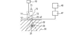
- FIG. 1 is a schematic diagram of a subject information acquisition apparatus according to this embodiment.
- the pulsed light emitted from the light source 10 is guided to the optical system 11 and irradiated onto the subject 30 as the irradiation light 12.
- the photoacoustic wave 32 generated from the light absorber 31 in the subject 30 is detected by the acoustic wave detector 20 including the acoustic wave detection elements e1, e2, and e3.
- the plurality of detection signals acquired by the acoustic wave detector 20 are amplified and digitally converted by the signal collector 47 and stored in the memory of the signal processing device 40.
- the initial sound pressure acquisition module 42 as the initial sound pressure acquisition unit provided in the signal processing device 40 as the signal processing means reconstructs an image using a plurality of detection signals, and thereby interests in the subject 30.
- the initial sound pressure in the area 33 is acquired.
- the light quantity value acquisition module 43 as a light quantity value acquisition unit provided in the signal processing device 40 acquires the integrated light quantity value in the region of interest 33.
- the optical characteristic value acquisition module 44 as an optical characteristic value acquisition unit provided in the signal processing device 40 acquires the optical characteristic value in the region of interest 33 using the initial sound pressure and the light amount value in the region of interest 33. And the acquired optical characteristic value is displayed on the display apparatus 50 as a display means.
- the region of interest refers to a voxel that is the minimum unit of the region reconstructed by the initial sound pressure acquisition module 42.
- the initial sound pressure acquisition module 42 can acquire the initial sound pressure distribution of the entire subject by setting the region of interest over the entire region of the subject 30.
- the light amount value acquisition module 43 and the optical characteristic value acquisition module 44 can acquire the integrated light amount value distribution and the absorption coefficient distribution of the entire subject by setting the region of interest over the entire region of the subject. it can.
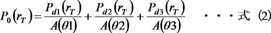
- P d1 (r T ), P d2 (r T ), P d3 (r T ) are detected signals corresponding to the region of interest 33 acquired by each of the acoustic wave detection elements e1, e2, e3 shown in FIG.
- the conversion efficiency of the photoacoustic wave that enters from the front of the acoustic wave detection element into the detection signal of the photoacoustic wave that enters at an angle of ⁇ from the front of the acoustic wave detection element is represented by A ( ⁇ ).
- the conversion efficiencies due to the directivities of the respective acoustic wave detection elements are A ( ⁇ 1), A ( ⁇ 2), It can be expressed as A ( ⁇ 3).
- the region of interest is set 33 to the position r T of the light absorber 31.
- the distance from the acoustic wave detection element to the region of interest 33 is r
- the propagation speed of the photoacoustic wave in the subject is c
- the initial sound pressure acquisition module 42 detects the detection signals P d1 (r T ), P d2 (r T ), P d3 (r T ) and the conversion efficiencies A ( ⁇ 1), A as shown in Equation (2).
- the initial sound pressure P 0 (r T ) in the region of interest 33 is acquired using ( ⁇ 2) and A ( ⁇ 3).
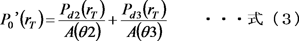
- a region (predetermined sensitivity region) where the conversion efficiency of the acoustic wave detection element is larger than a predetermined value is indicated by a dotted triangular region.
- the conversion efficiency A ( ⁇ ) 0.5 is set as a predetermined value.
- the region of interest 33 is not included in the triangular region (predetermined sensitivity region) corresponding to the acoustic wave detection element e1. Therefore, the initial sound pressure obtaining module 42, without using the detection signal corresponding to the region of interest 33 in which the acoustic wave detecting element e1 is obtained P d1 (r T), the initial sound in the region of interest 33 of the formula (3) The pressure P 0 ′ (r T ) is acquired.
- the light amount acquisition module 43 acquires the integrated light amount value in the subject using the light propagation Monte Carlo method, the transport equation, the light diffusion equation, or the like from the background optical coefficient of the subject.
- the light quantity value acquisition module 43 includes the light quantity values ⁇ 1 (r T ) and ⁇ in the region of interest 33 corresponding to the detection signals P d1 (r T ), P d2 (r T ), and P d3 (r T ). 2 (r T ) and ⁇ 3 (r T ) are calculated.
- the light quantity value obtaining module 43 obtains the integrated light quantity value [Phi (r T) in the region of interest 33 of the formula (4) using these.
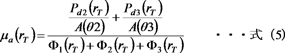
- the optical characteristic value acquisition module 44 has an initial sound pressure P 0 ′ (r T ) in the region of interest 33 shown in Expression (3) and an integrated light amount value ⁇ (r T ) in the region of interest 33 shown in Expression (4). ) To obtain the absorption coefficient ⁇ a (r T ) in the region of interest 33 shown in Expression (5).
- S100 a step of setting a predetermined sensitivity region based on the sensitivity distribution of the acoustic wave detection element
- a predetermined sensitivity region corresponding to each of the plurality of acoustic wave detection elements is set based on the sensitivity distribution of the plurality of acoustic wave detection elements.
- a table of predetermined sensitivity regions corresponding to each acoustic wave detection element is stored in the memory of the signal processing device 40.
- the setting module 41 as a setting unit provided in the signal processing device 40 may set a region where the sensitivity of the acoustic wave detection element is larger than a predetermined value as the predetermined sensitivity region.
- the predetermined value may be automatically set by the setting module 41 based on the system noise.
- the predetermined value may be displayed on the display device 50 as a sensitivity of the acoustic wave detection element as a histogram, and the operator may select the predetermined value based on the histogram. At this time, the predetermined value is preferably selected in consideration of system noise.
- the sensitivity of the acoustic wave detection element is determined by, for example, the conversion efficiency of the acoustic wave detection element, the attenuation rate indicating attenuation due to diffusion or scattering of the photoacoustic wave from the region of interest to the acoustic wave detection element, and the like. .
- the conversion efficiency is determined by the angle at which the photoacoustic wave is incident on the acoustic wave detection element.
- the attenuation rate is determined by the distance between the region of interest and the acoustic wave detection element.
- the image data of the sensitivity distribution of the acoustic wave detection element stored in the memory of the signal processing device 40 is displayed on the display device 50. Then, the worker selects an arbitrary region from the displayed sensitivity distribution image using the PC input device. Then, the setting module 41 can set the selected arbitrary region as a predetermined sensitivity region. At this time, for example, while displaying an image of the sensitivity distribution, an arbitrary region can be selected by connecting from the start point to the end point by the recognition by the mouse or the recognition method by the sensor on the touch panel.
- the setting module 41 may set as a predetermined sensitivity region based on the sensitivity distribution of the selected arbitrary region. For example, a predetermined sensitivity region can be set with the smallest sensitivity as a reference.
- a predetermined sensitivity region may be set individually for each acoustic wave detection element, or a predetermined sensitivity region is set for one acoustic wave detection element, and the same sensitivity region as the predetermined sensitivity region is set. May be set for other acoustic wave detection elements.
- S200 A step of acquiring the initial sound pressure in the region of interest without using the detection signal acquired by the acoustic wave detection element whose region of interest is not included in the predetermined sensitivity region
- the detection signal corresponding to the region of interest acquired by the acoustic wave detection element is not used, and the initial value in the region of interest. Get sound pressure. Then, the initial sound pressure data is stored in the memory of the signal processing device 40.
- the initial sound pressure acquisition module 42 detects the detection signal corresponding to the region of interest acquired by the acoustic wave detection element e1 among the detection signals P d1 (r T ), P d2 (r T ), and P d3 (r T ).
- the initial sound pressure P 0 ′ (r T ) represented by the equation (4) is acquired.
- the image reconstruction algorithm performed by the initial sound pressure acquisition module 42 includes, for example, back projection in the time domain or Fourier domain normally used in the tomography technique.
- a predetermined sensitivity region is included in a part of the region of interest, it can be assumed that the region of interest is included in the predetermined sensitivity region.
- not using a detection signal is a concept including not using a detection signal at all and acquiring substantially no detection signal when acquiring an initial sound pressure.
- Step 300 Step of acquiring the integrated light amount value in the region of interest without using the light amount value corresponding to the detection signal not used when acquiring the initial sound pressure
- the integrated light amount value in the region of interest is acquired without using the light amount value in the region of interest corresponding to the detection signal not used in S200.
- the integrated light quantity value data is stored in the memory of the signal processing device 40.
- the light quantity value acquisition module 43 detects the detection signal P d1 (r) that is not used by the initial sound pressure acquisition module 42 among the light quantity values ⁇ 1 (r T ), ⁇ 2 (r T ), and ⁇ 3 (r T ). without using the light quantity value ⁇ 1 (r T) in the region of interest corresponding to T), to obtain the formula (integrated light intensity values in the region of interest indicated by 6) ⁇ '(r T) .
- the light amount acquisition module 43 acquires the integrated light amount value in the region of interest using the light amount value in the region of interest corresponding to the detection signal used when the initial sound pressure acquisition module 42 calculates the initial sound pressure. ing.
- not using a light amount value is a concept including not using a light amount value at all and not substantially using a light amount value when acquiring an integrated light amount value.
- the light amount acquisition module 43 calculates a value obtained by multiplying the number of detection signals used when the initial sound pressure acquisition module 42 acquires the initial sound pressure by the amount of light reaching the region of interest 33. You may acquire as an integrated light quantity value in 33. In the present invention, the integrated light quantity value acquired in this way is also handled as an integrated light quantity value acquired without using the light quantity value.
- Step 400 Step of obtaining an optical characteristic value in the region of interest using the initial sound pressure and the integrated light amount value in the region of interest
- an absorption coefficient as an optical characteristic value in the region of interest is acquired using the initial sound pressure in the region of interest acquired in S200 and the integrated light amount value in the region of interest acquired in S300.
- the optical characteristic value acquisition module 44 uses the initial sound pressure P 0 ′ (r T ) shown in Equation (3) and the integrated light amount value ⁇ ′ shown in Equation (6). (R T ) is applied to Equation (1). Then, the absorption coefficient ⁇ a (r T ) in the region of interest 33 represented by Expression (7) is acquired.
- the Gruneisen coefficient ⁇ 1.
- the detection signal corresponding to the region of interest acquired by the acoustic wave detection element and the light amount value in the region of interest corresponding to the detection signal By not using the above, it is possible to obtain an absorption coefficient having a high quantitative property with less error due to noise.
- a program including the above steps may be executed by the signal processing device 40 as a computer.
- (Second Embodiment) 3A to 3C are schematic views of the subject information acquiring apparatus according to the present embodiment.
- the subject information acquisition apparatus includes an acoustic wave detector 20 including one acoustic wave detection element. Further, a detector scanning mechanism 21 for relatively moving the subject 30 and the acoustic wave detector 20 is provided. In the present embodiment, the detector scanning mechanism 21 is capable of detecting photoacoustic waves at a plurality of positions by scanning the acoustic wave detector 20 having one acoustic wave detection element in the right direction on the paper surface.
- the acoustic wave detection elements at the respective positions shown in FIGS. 3A, 3B, and 3C are denoted by e1, e2, and e3.
- region shown with the dotted line shows the predetermined
- the plurality of acoustic wave detecting elements means that the acoustic wave detecting elements can detect photoacoustic waves at a plurality of positions. That is, as in the present embodiment, an acoustic wave detection element that can detect photoacoustic waves at a plurality of positions by scanning the acoustic wave detector 20 is also a plurality of acoustic wave detection elements.
- the subject information acquiring apparatus is provided with an optical scanning mechanism 13 that scans the optical system 11 in order to scan the irradiation light 12.
- the acoustic wave detector 20 and the irradiation light 12 are scanned synchronously. In this way, by scanning the acoustic wave detector 20 and the irradiation light 12 in synchronization, the irradiation light 12 is always irradiated to a predetermined sensitivity region (triangular region) corresponding to the acoustic wave detection element. A detection signal with a high S / N can always be obtained.
- the region of interest 33 is not included in the predetermined sensitivity region corresponding to the acoustic wave detection element e1 as in the first embodiment. Therefore, the initial sound pressure acquisition module 42 acquires the initial sound pressure in the region of interest 33 without using the detection signal corresponding to the region of interest 33 acquired by the acoustic wave detection element e1. Then, the light amount value acquisition module 43 acquires the integrated light amount value in the region of interest 33 without using the light amount value in the region of interest 33 corresponding to the detection signal not used when acquiring the initial sound pressure. Then, the optical characteristic value acquisition module 44 acquires the absorption coefficient in the region of interest 33 represented by Expression (7) using the initial sound pressure and the integrated light quantity value. By acquiring the absorption coefficient in this way, the absorption coefficient can be acquired with high accuracy also in the present embodiment.
- a detection signal corresponding to the region of interest acquired by the acoustic wave detection element, and the The absorption coefficient is acquired without using the light amount value in the region of interest corresponding to the detection signal.
- the absorption coefficient is acquired by reducing the detection signal and the light amount value in the region of interest corresponding to the detection signal.
- the initial sound pressure acquisition module 42 applies the first reduction coefficient to the detection signal corresponding to the region of interest 33 acquired by the acoustic wave detection element e1 that does not include the region of interest 33 in the predetermined sensitivity region. Multiply.
- the initial sound pressure acquisition module 42 acquires the initial sound pressure in the region of interest 33 using the detection signal multiplied by the first reduction coefficient.
- the detection signal corresponding to the region of interest acquired by the acoustic wave detection element is multiplied by the first reduction coefficient to obtain S /
- the initial sound pressure can be acquired by reducing the detection signal having a low N. Therefore, it is possible to acquire an initial sound pressure with little error due to noise.
- the light quantity value acquisition module 43 multiplies the light quantity value in the region of interest 33 corresponding to the detection signal multiplied by the first reduction coefficient by the second reduction coefficient. And the light quantity value acquisition module 43 acquires the integrated light quantity value in the region of interest 33 using the light quantity value multiplied by the second reduction coefficient.
- the optical characteristic value acquisition module 44 acquires the absorption coefficient in the region of interest 33 by using the initial sound pressure acquired by the initial sound pressure acquisition module 42 and the integrated light amount value acquired by the light amount value acquisition module 43.
- the absorption coefficient can be obtained with high accuracy by multiplying the light quantity value corresponding to the detection signal by the second reduction coefficient.
- first reduction coefficient and the second reduction coefficient are values smaller than 1. Further, another reduction coefficient may be set depending on the region of interest.
- the first reduction coefficient and the second reduction coefficient are preferably the same value.
- the same value is a concept that includes a completely same value and a value that is substantially the same when acquiring the absorption coefficient.
- the present invention is also applicable to the subject information acquiring apparatus shown in FIGS. 4A to 4C and the subject information acquiring apparatus shown in FIGS. 5A to 5C.
- the detector scanning mechanism 21 rotates and scans the acoustic wave detector 20 around the subject 30 so that photoacoustic waves can be detected at a plurality of positions.
- the subject 30 is immersed in water 51 filled in a water tank 52 in order to achieve acoustic impedance matching between the subject 30 and the acoustic wave detector 20.
- a subject scanning mechanism 34 that scans the subject 30 is provided.
- the subject scanning mechanism 34 scans the subject in the downward direction on the sheet from the state shown in FIG. 4A, so that the state shown in FIG. Then, when the detector scanning mechanism 21 scans the acoustic wave detector 20 from the state of FIG. 4B, the state of FIG. 4C is obtained.
- the acoustic wave detection elements in the respective states of FIGS. 4A, 4B, and 4C be e1, e2, and e3.
- region shown with the dotted line shows the predetermined
- the object information acquiring apparatus shown in FIGS. 5A to 5C is provided with the acoustic wave detector 20 and the optical system 11 housed in one housing 70.
- the housing 70 also includes a handheld mechanism 71 that allows the operator to grip the handheld mechanism 71 and scan the housing 70. By scanning the housing 70 in this manner, the acoustic wave detection element can detect photoacoustic waves at a plurality of positions. 5A to 5C, the operator grasps the hand-held mechanism 71 and scans the housing 70 in the right direction on the paper surface, so that the acoustic wave detecting element detects the photoacoustic wave.
- the acoustic wave detection elements in the respective states of FIGS. 5A, 5B, and 5C be e1, e2, and e3.
- region shown with the dotted line shows the predetermined
- this embodiment does not mechanically scan the acoustic wave detector 20, but the operator grips the handheld mechanism 71 and freely scans the housing 70. Therefore, the positional relationship between the acoustic wave detector 20 and the region of interest 33 when the photoacoustic wave 32 is detected cannot be grasped.
- the housing 70 includes the position detector 72 for detecting the position of the housing 70, that is, the position of the acoustic wave detector 20 and the optical system 11 housed in the housing 70. .
- the region of interest 33 is not included in the predetermined sensitivity region corresponding to the acoustic wave detection element e1. Therefore, the signal processing device 40 uses the subject information acquisition method described in the first and second embodiments and the subject information acquisition method described in the third embodiment to calculate the absorption coefficient of the region of interest 33. Can be acquired. By acquiring the absorption coefficient in this way, the absorption coefficient can be acquired with high accuracy also in the present embodiment.
- the light source 10 includes a light source capable of generating pulsed light of 5 to 50 nanoseconds. Although a laser capable of obtaining a large output is preferable as the light source, a light emitting diode or the like can be used instead of the laser. As the laser, various lasers such as a solid laser, a gas laser, a dye laser, and a semiconductor laser can be used. Ideally, an Nd: YAG-excited Ti: sa laser or an alexandrite laser that has a strong output and can continuously change the wavelength is preferable. A plurality of single wavelength lasers having different wavelengths may be held.
- the pulsed light emitted from the light source 10 is typically guided to the subject while being processed into a desired light distribution shape by an optical component such as a lens or a mirror, but propagates using an optical waveguide such as an optical fiber. It is also possible to make it.
- the optical system 11 is, for example, a mirror that reflects light, a lens that collects or enlarges light, or changes its shape, or a diffusion plate that diffuses light.
- any optical component may be used as long as pulse light emitted from a light source is irradiated in a desired shape on the subject.
- an optical scanning mechanism may be provided in the optical system 11 in order to scan the irradiation light.
- the acoustic wave detector 20 which is a detector that detects photoacoustic waves generated on the subject surface and inside the subject by light, detects the acoustic waves and converts them into electrical signals that are analog signals. Hereinafter, it may be simply referred to as a probe or a transducer. Any acoustic wave detector may be used as long as it can detect an acoustic wave signal, such as a transducer using a piezoelectric phenomenon, a transducer using optical resonance, or a transducer using a change in capacitance.
- the acoustic wave detector 20 includes a plurality of acoustic wave detection elements. By arranging the plurality of acoustic wave detection elements in a one-dimensional or two-dimensional array in an array, photoacoustic waves can be detected at a plurality of positions. By using such a multidimensional array element, acoustic waves can be detected at a plurality of positions simultaneously, so that the detection time can be shortened and the influence of vibration of the subject can be reduced.
- the acoustic wave detector 20 may be configured to be mechanically scanable by the detector scanning mechanism 21 in order to enable detection of photoacoustic waves at a plurality of positions.
- a handheld mechanism that can be gripped by an operator and freely scanned by the acoustic wave detector 20 can be provided.
- the signal collector 47 It is preferable to have a signal collector 47 that amplifies the electrical signal obtained from the acoustic wave detector 20 and converts the electrical signal from an analog signal to a digital signal.
- the signal collector 47 is typically composed of an amplifier, an A / D converter, an FPGA (Field Programmable Gate Array) chip, and the like.
- FPGA Field Programmable Gate Array
- the “detection signal” is a concept including an analog signal output from the acoustic wave detector 20 and a digital signal AD-converted by the signal collector 47.
- the signal processing device 40 acquires an optical characteristic value inside the subject by performing image reconstruction or the like.
- a workstation or the like is typically used, and image reconstruction processing or the like is performed by software programmed in advance.
- software used in the workstation includes a setting module 41, an initial sound pressure acquisition module 42, a light amount acquisition module 43, an optical characteristic value acquisition module 44, and the like.
- each module may be provided as separate hardware.
- the respective hardware may be collectively used as the signal processing device 40.
- the signal collector 47 and the signal processing device 40 may be integrated.
- the optical characteristic value of the subject can be generated not by software processing as performed at the workstation but by hardware processing.
Landscapes
- Life Sciences & Earth Sciences (AREA)
- Health & Medical Sciences (AREA)
- Physics & Mathematics (AREA)
- Molecular Biology (AREA)
- Animal Behavior & Ethology (AREA)
- Pathology (AREA)
- Engineering & Computer Science (AREA)
- Biomedical Technology (AREA)
- Heart & Thoracic Surgery (AREA)
- Medical Informatics (AREA)
- Acoustics & Sound (AREA)
- Surgery (AREA)
- Biophysics (AREA)
- General Health & Medical Sciences (AREA)
- Public Health (AREA)
- Veterinary Medicine (AREA)
- Ultra Sonic Daignosis Equipment (AREA)
- Investigating Or Analyzing Materials By The Use Of Ultrasonic Waves (AREA)
- Breeding Of Plants And Reproduction By Means Of Culturing (AREA)
- Pharmaceuticals Containing Other Organic And Inorganic Compounds (AREA)
Description
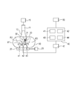
図1は、本実施形態に係る被検体情報取得装置の模式図である。光源10から発したパルス光は、光学系11に導かれ、照射光12として被検体30に照射される。被検体30内の光吸収体31から発生した光音響波32は、音響波検出素子e1,e2,e3を備えた音響波検出器20で検出される。そして、音響波検出器20が取得した複数の検出信号は、信号収集器47で増幅、デジタル変換され、信号処理装置40のメモリに格納される。そして、信号処理手段としての信号処理装置40に備えられた初期音圧取得部としての初期音圧取得モジュール42は、複数の検出信号を用いて画像再構成することにより、被検体30内の関心領域33における初期音圧を取得する。また、信号処理装置40に備えられた光量値取得部としての光量値取得モジュール43は、関心領域33における積算光量値を取得する。そして、信号処理装置40に備えられた光学特性値取得部としての光学特性値取得モジュール44は、関心領域33における初期音圧及び光量値を用いて、関心領域33における光学特性値を取得する。そして、取得した光学特性値を表示手段としての表示装置50に表示させる。
以下に、図1を用いて、音響波検出素子の感度に基づき、一部の検出信号を用いずに取得した初期音圧より、吸収係数を取得するシミュレーションの例を説明する。本シミュレーションでは、光吸収体31の吸収係数を、μa=0.088/mmと設定した。
Pd1(rT)=132Pa
Pd2(rT)=231Pa
Pd3(rT)=198Pa
A(θ1)=0.4
A(θ2)=0.7
A(θ3)=0.6
Φ1(rT)=3750mJ/m2
Φ2(rT)=3750mJ/m2
Φ3(rT)=3750mJ/m2
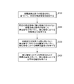
そこで、以下に、本発明者が見出した本実施形態に係る被検体情報取得方法を、図2のフローチャートを用いて説明する。以下の番号は、図2に示す処理番号と一致する。
この工程では、複数の音響波検出素子の感度分布に基づいて、複数の音響波検出素子のそれぞれに対応する所定の感度領域を設定する。それぞれの音響波検出素子に対応する所定の感度領域のテーブルを、信号処理装置40のメモリに格納する。
この工程では、S100で設定した所定の感度領域に、関心領域が含まれない音響波検出素子について、その音響波検出素子が取得した関心領域に対応する検出信号を用いずに、関心領域における初期音圧を取得する。そして、この初期音圧のデータを信号処理装置40のメモリに格納する。
この工程では、S200で用いなかった検出信号に対応する、関心領域における光量値を用いずに、関心領域における積算光量値を取得する。そして、この積算光量値のデータを、信号処理装置40のメモリに格納する。
この工程では、S200で取得した関心領域における初期音圧と、S300で取得した関心領域における積算光量値とを用いて、関心領域における光学特性値としての吸収係数を取得する。
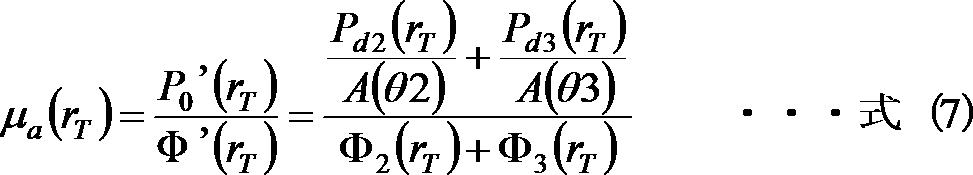
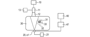
図3A~3Cは、本実施形態に係る被検体情報取得装置の模式図である。
第1の実施形態および第2の実施形態では、所定の感度領域に関心領域が含まれていない音響波検出素子について、その音響波検出素子が取得した関心領域に対応する検出信号、および、その検出信号に対応する関心領域における光量値を用いずに吸収係数を取得していた。一方、本実施形態では、上記検出信号と、この検出信号に対応する関心領域における光量値とを低減して、吸収係数を取得する。
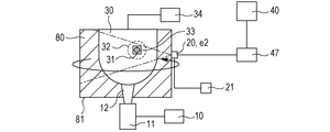
本発明は、図4A~4Cに示される被検体情報取得装置や、図5A~5Cに示される被検体情報取得装置にも適用可能である。図4A~4Cに示す被検体情報取得装置は、検出器走査機構21が音響波検出器20を被検体30の周囲を回転走査することにより、複数の位置で光音響波を検出可能としている。また、被検体30と音響波検出器20との間の音響インピーダンスマッチングを図るために、被検体30は水槽52に満たされた水51に浸かっている。また、被検体30を走査する被検体走査機構34を有している。このような構成とすることで、保持板等で形状を規定出来ない部位でも測定可能となる。また、被検体に対して多くの方向に検出素子を設置可能となるため、情報量の多いデータの取得が可能となる。
光源10は、5ナノ秒乃至50ナノ秒のパルス光を発生可能な光源を備えている。光源としては大きな出力が得られるレーザーが好ましいが、レーザーのかわりに発光ダイオードなどを用いることも可能である。レーザーとしては、固体レーザー、ガスレーザー、色素レーザー、半導体レーザーなど様々なレーザーを使用することができる。理想的には、出力が強く連続的に波長を変えられる、Nd:YAG励起のTi:saレーザーや、アレキサンドライトレーザーがよい。異なる波長の単波長レーザーを複数で保有していてもよい。
光源10から出射されたパルス光は、典型的にはレンズやミラーなどの光学部品により、所望の光分布形状に加工されながら被検体に導かれるが、光ファイバなどの光導波路などを用いて伝搬させることも可能である。光学系11は、例えば、光を反射するミラーや、光を集光したり拡大したり形状を変化させるレンズ、光を拡散させる拡散板などである。このような光学部品は、光源から発せられたパルス光が被検体に所望の形状で照射されれば、どのようなものを用いてもかまわない。なお、光はレンズで集光させるより、ある程度の面積に広げる方が被検体への安全性ならびに診断領域を広げられるという観点で好ましい。なお、照射光を走査するために、光学系11に光学走査機構を設けてもよい。
光により被検体表面及び被検体内部で発生する光音響波を検出する検出器である音響波検出器20は、音響波を検知し、アナログ信号である電気信号に変換するものである。以後、単に探触子あるいはトランスデューサということもある。圧電現象を用いたトランスデューサ、光の共振を用いたトランスデューサ、容量の変化を用いたトランスデューサなど音響波信号を検知できるものであれば、どのような音響波検出器を用いてもよい。
音響波検出器20より得られた電気信号を増幅し、その電気信号をアナログ信号からデジタル信号に変換する信号収集器47を有することが好ましい。信号収集器47は、典型的には増幅器、A/D変換器、FPGA(Field Programmable Gate Array)チップなどで構成される。音響波検出器から得られる検出信号が複数の場合は、同時に複数の信号を処理できることが望ましい。それにより、画像を形成するまでの時間を短縮できる。なお、本明細書において「検出信号」とは、音響波検出器20から出力されるアナログ信号も、信号収集器47によりAD変換されたデジタル信号も含む概念である。
信号処理装置40は、画像再構成などを行うことにより被検体内部の光学特性値を取得する。信号処理装置40には、典型的にはワークステーションなどが用いられ、画像再構成処理などがあらかじめプログラミングされたソフトウェアにより行われる。例えば、ワークステーションで使われるソフトウェアとしては、設定モジュール41、初期音圧取得モジュール42、光量値取得モジュール43、光学特性値取得モジュール44などがある。
30 被検体
40 信号処理装置
41 設定モジュール
42 初期音圧取得モジュール
43 光量値取得モジュール
44 光学特性値取得モジュール
Claims (10)
- 被検体に光を照射することにより発生した光音響波を検出する複数の音響波検出素子を備える音響波検出器と、
前記複数の音響波検出素子が取得した、前記被検体内の関心領域に対応する複数の検出信号と、前記関心領域における積算光量値と、を用いて前記関心領域における光学特性値を取得する信号処理手段と、
を有する被検体情報取得装置において、
前記信号処理手段は、
前記複数の音響波検出素子の感度分布に基づき、所定の感度領域を設定する設定部と、
前記所定の感度領域に前記関心領域が含まれていない音響波検出素子が取得した、前記関心領域に対応する検出信号を用いずに、前記関心領域における初期音圧を取得する初期音圧取得部と、
前記初期音圧取得部が用いない検出信号に対応する、前記関心領域における光量値を用いずに、前記関心領域における積算光量値を取得する光量値取得部と、
前記初期音圧取得部が取得した初期音圧と、前記光量値取得部が取得した積算光量値と、を用いて、前記関心領域における光学特性値を取得する光学特性値取得部と、
を備えることを特徴とする被検体情報取得装置。 - 前記設定部は、音響波検出素子の感度分布のうち、所定の値より大きい感度の領域を、前記所定の感度領域として設定することを特徴とする請求項1に記載の被検体情報取得装置。
- 音響波検出素子の感度分布に基づき、前記音響波検出素子の感度分布の画像を表示する表示手段を有し、
前記設定部は、前記表示手段に表示された前記音響波検出素子の感度分布の画像から選択された任意の領域に基づいた領域を、前記所定の感度領域として設定することを特徴とする請求項1に記載の被検体情報取得装置。 - 前記音響波検出器と、前記被検体とを相対的に移動させる走査機構を有することを特徴とする請求項1から3のいずれか1項に記載の被検体情報取得装置。
- 前記音響波検出素子の感度は、前記音響波検出素子の前記光音響波から前記検出信号への変換効率、及び前記関心領域から前記音響波検出素子までの前記光音響波の減衰率のうち少なくとも1つに基づいて設定されることを特徴とする請求項1から4のいずれか1項に記載の被検体情報取得装置。
- 被検体に光を照射することにより発生した光音響波を検出する複数の音響波検出素子を備える音響波検出器と、
前記複数の音響波検出素子が取得した、前記被検体内の関心領域に対応する複数の検出信号と、前記関心領域における積算光量値と、を用いて前記関心領域における光学特性値を取得する信号処理手段と、
を有する被検体情報取得装置において、
前記信号処理手段は、
前記複数の音響波検出素子の感度分布に基づき、所定の感度領域を設定する設定部と、
前記所定の感度領域に前記関心領域が含まれていない音響波検出素子が取得した、前記関心領域に対応する検出信号に、第1の低減係数を掛けて、前記関心領域における初期音圧を取得する初期音圧取得部と、
前記初期音圧取得部が前記第1の低減係数を掛けた検出信号に対応する、前記関心領域における光量値に、第2の低減係数を掛けて、前記関心領域における積算光量値を取得する光量値取得部と、
前記初期音圧取得部が取得した初期音圧と、前記光量値取得部が取得した積算光量値と、を用いて、前記関心領域における光学特性値を取得する光学特性値取得部と、
を備えることを特徴とする被検体情報取得装置。 - 前記第1の低減係数と、前記第2の低減係数と、は同一の値であることを特徴とする請求項6に記載の被検体情報取得装置。
- 被検体に光を照射することにより発生した光音響波を複数の音響波検出素子が検出し、前記被検体内の関心領域における複数の検出信号を取得する工程と、
前記複数の検出信号と、前記関心領域における積算光量値と、を用いて前記関心領域における光学特性値を取得する工程と、
を有する被検体情報取得方法において、
前記複数の音響波検出素子の感度分布に基づき、所定の感度領域を設定する工程と、
前記所定の感度領域に前記関心領域が含まれていない音響波検出素子が取得した、前記関心領域に対応する検出信号を用いずに、前記関心領域における初期音圧を取得する工程と、
前記初期音圧を取得する工程で用いない検出信号に対応する、前記関心領域における光量値を用いずに、前記関心領域における積算光量値を取得する工程と、
前記初期音圧を取得する工程で取得した初期音圧と、前記積算光量値を取得する工程で取得した積算光量値と、を用いて、前記関心領域における光学特性値を取得する工程と、
を有することを特徴とする被検体情報取得方法。 - 被検体に光を照射することにより発生した光音響波を複数の音響波検出素子が検出し、前記被検体内の関心領域における複数の検出信号を取得する工程と、
前記複数の検出信号と、前記関心領域における積算光量値と、を用いて前記関心領域における光学特性値を取得する工程と、
を有する被検体情報取得方法において、
前記複数の音響波検出素子の感度分布に基づき、所定の感度領域を設定する工程と、
前記所定の感度領域に前記関心領域が含まれていない音響波検出素子が取得した、前記関心領域に対応する検出信号に、第1の低減係数を掛けて、前記関心領域における初期音圧を取得する工程と、
前記初期音圧を取得する工程で前記第1の低減係数を掛けた検出信号に対応する、前記関心領域における光量値に、第2の低減係数を掛けて、前記関心領域における積算光量値を取得する工程と、
前記初期音圧を取得する工程で取得した初期音圧と、前記積算光量値を取得する工程で取得した積算光量値と、を用いて、前記関心領域における光学特性値を取得する工程と、
を有することを特徴とする被検体情報取得方法。 - 請求項8または9に記載の被検体情報取得方法をコンピュータに実行させることを特徴とするプログラム。
Priority Applications (8)
| Application Number | Priority Date | Filing Date | Title |
|---|---|---|---|
| JP2013554144A JP5871958B2 (ja) | 2012-01-18 | 2012-01-18 | 被検体情報取得装置及び被検体情報取得方法 |
| EP12866220.2A EP2805676A4 (en) | 2012-01-18 | 2012-01-18 | DEVICE FOR COLLECTING PERSONNEL INFORMATION AND METHOD FOR DETECTING PERSONNEL INFORMATION |
| RU2014133557/14A RU2602718C2 (ru) | 2012-01-18 | 2012-01-18 | Устройство для получения информации о субъекте и способ получения информации в отношении субъекта |
| BR112014017377A BR112014017377A8 (pt) | 2012-01-18 | 2012-01-18 | aparelho de obtenção de informação de indivíduo e método para obter informação com relação ao indivíduo |
| CN201280067433.8A CN104053402B (zh) | 2012-01-18 | 2012-01-18 | 被检体信息获得设备和关于被检体的信息的获得方法 |
| PCT/JP2012/050914 WO2013108375A1 (ja) | 2012-01-18 | 2012-01-18 | 被検体情報取得装置及び被検体情報取得方法 |
| US13/741,711 US20130197343A1 (en) | 2012-01-18 | 2013-01-15 | Subject information obtaining apparatus and method for obtaining information regarding subject |
| US15/699,790 US20180028067A1 (en) | 2012-01-18 | 2017-09-08 | Subject information obtaining apparatus and method for obtaining information regarding subject |
Applications Claiming Priority (1)
| Application Number | Priority Date | Filing Date | Title |
|---|---|---|---|
| PCT/JP2012/050914 WO2013108375A1 (ja) | 2012-01-18 | 2012-01-18 | 被検体情報取得装置及び被検体情報取得方法 |
Publications (2)
| Publication Number | Publication Date |
|---|---|
| WO2013108375A1 true WO2013108375A1 (ja) | 2013-07-25 |
| WO2013108375A9 WO2013108375A9 (ja) | 2014-06-19 |
Family
ID=48798824
Family Applications (1)
| Application Number | Title | Priority Date | Filing Date |
|---|---|---|---|
| PCT/JP2012/050914 Ceased WO2013108375A1 (ja) | 2012-01-18 | 2012-01-18 | 被検体情報取得装置及び被検体情報取得方法 |
Country Status (7)
| Country | Link |
|---|---|
| US (2) | US20130197343A1 (ja) |
| EP (1) | EP2805676A4 (ja) |
| JP (1) | JP5871958B2 (ja) |
| CN (1) | CN104053402B (ja) |
| BR (1) | BR112014017377A8 (ja) |
| RU (1) | RU2602718C2 (ja) |
| WO (1) | WO2013108375A1 (ja) |
Cited By (3)
| Publication number | Priority date | Publication date | Assignee | Title |
|---|---|---|---|---|
| WO2015129293A1 (ja) * | 2014-02-26 | 2015-09-03 | オリンパス株式会社 | 光音響顕微鏡装置 |
| JP2015216979A (ja) * | 2014-05-14 | 2015-12-07 | キヤノン株式会社 | 光音響装置 |
| JP2017094169A (ja) * | 2017-01-25 | 2017-06-01 | キヤノン株式会社 | 被検体情報取得装置及び被検体情報取得方法 |
Families Citing this family (4)
| Publication number | Priority date | Publication date | Assignee | Title |
|---|---|---|---|---|
| JP2013255585A (ja) * | 2012-06-11 | 2013-12-26 | Canon Inc | 被検体情報取得装置、および、光音響プローブ |
| EP3238630A4 (en) * | 2014-12-22 | 2018-09-05 | Olympus Corporation | Ultrasound observation apparatus, ultrasound observation apparatus operation method, and ultrasound observation apparatus operation program |
| JP2017070385A (ja) * | 2015-10-06 | 2017-04-13 | キヤノン株式会社 | 被検体情報取得装置およびその制御方法 |
| JP2018117709A (ja) * | 2017-01-23 | 2018-08-02 | キヤノン株式会社 | 光音響装置 |
Citations (3)
| Publication number | Priority date | Publication date | Assignee | Title |
|---|---|---|---|---|
| JP2006051355A (ja) | 2004-08-10 | 2006-02-23 | General Electric Co <Ge> | 調整可能な開口制御を伴う超音波空間複合イメージングための方法及び装置 |
| JP2010088627A (ja) | 2008-10-07 | 2010-04-22 | Canon Inc | 生体情報処理装置および生体情報処理方法 |
| JP2011245277A (ja) * | 2010-04-27 | 2011-12-08 | Canon Inc | 表示データ取得装置及び表示データ取得方法 |
Family Cites Families (13)
| Publication number | Priority date | Publication date | Assignee | Title |
|---|---|---|---|---|
| JP2006516207A (ja) * | 2003-01-13 | 2006-06-29 | グルコン インク | 光音響分析方法及び装置 |
| US8317702B2 (en) * | 2003-06-20 | 2012-11-27 | U-Systems, Inc. | Full-field breast ultrasound system and architecture |
| US7806122B2 (en) * | 2007-05-11 | 2010-10-05 | Medtronic, Inc. | Septum port locator system and method for an implantable therapeutic substance delivery device |
| JP4739363B2 (ja) * | 2007-05-15 | 2011-08-03 | キヤノン株式会社 | 生体情報イメージング装置、生体情報の解析方法、及び生体情報のイメージング方法 |
| CN102512175B (zh) * | 2007-11-05 | 2015-12-02 | 生物传感器公司 | 用于测定分析物浓度的光学传感器 |
| JP5541662B2 (ja) * | 2008-09-12 | 2014-07-09 | キヤノン株式会社 | 被検体情報取得装置およびその制御方法 |
| US20100094134A1 (en) * | 2008-10-14 | 2010-04-15 | The University Of Connecticut | Method and apparatus for medical imaging using near-infrared optical tomography combined with photoacoustic and ultrasound guidance |
| JP2011005042A (ja) * | 2009-06-26 | 2011-01-13 | Canon Inc | 光音響イメージング装置及び光音響イメージング方法 |
| US8862206B2 (en) * | 2009-11-12 | 2014-10-14 | Virginia Tech Intellectual Properties, Inc. | Extended interior methods and systems for spectral, optical, and photoacoustic imaging |
| JP5528083B2 (ja) * | 2009-12-11 | 2014-06-25 | キヤノン株式会社 | 画像生成装置、画像生成方法、及び、プログラム |
| JP5419727B2 (ja) * | 2010-01-22 | 2014-02-19 | キヤノン株式会社 | 画像形成方法及び音響波測定装置 |
| JP5393552B2 (ja) * | 2010-03-19 | 2014-01-22 | キヤノン株式会社 | 測定装置 |
| JP5641773B2 (ja) * | 2010-04-28 | 2014-12-17 | キヤノン株式会社 | 測定装置 |
-
2012
- 2012-01-18 JP JP2013554144A patent/JP5871958B2/ja not_active Expired - Fee Related
- 2012-01-18 RU RU2014133557/14A patent/RU2602718C2/ru active
- 2012-01-18 WO PCT/JP2012/050914 patent/WO2013108375A1/ja not_active Ceased
- 2012-01-18 EP EP12866220.2A patent/EP2805676A4/en not_active Withdrawn
- 2012-01-18 CN CN201280067433.8A patent/CN104053402B/zh not_active Expired - Fee Related
- 2012-01-18 BR BR112014017377A patent/BR112014017377A8/pt not_active Application Discontinuation
-
2013
- 2013-01-15 US US13/741,711 patent/US20130197343A1/en not_active Abandoned
-
2017
- 2017-09-08 US US15/699,790 patent/US20180028067A1/en not_active Abandoned
Patent Citations (3)
| Publication number | Priority date | Publication date | Assignee | Title |
|---|---|---|---|---|
| JP2006051355A (ja) | 2004-08-10 | 2006-02-23 | General Electric Co <Ge> | 調整可能な開口制御を伴う超音波空間複合イメージングための方法及び装置 |
| JP2010088627A (ja) | 2008-10-07 | 2010-04-22 | Canon Inc | 生体情報処理装置および生体情報処理方法 |
| JP2011245277A (ja) * | 2010-04-27 | 2011-12-08 | Canon Inc | 表示データ取得装置及び表示データ取得方法 |
Non-Patent Citations (1)
| Title |
|---|
| See also references of EP2805676A4 * |
Cited By (4)
| Publication number | Priority date | Publication date | Assignee | Title |
|---|---|---|---|---|
| WO2015129293A1 (ja) * | 2014-02-26 | 2015-09-03 | オリンパス株式会社 | 光音響顕微鏡装置 |
| US10209226B2 (en) | 2014-02-26 | 2019-02-19 | Olympus Corporation | Photoacoustic microscope apparatus |
| JP2015216979A (ja) * | 2014-05-14 | 2015-12-07 | キヤノン株式会社 | 光音響装置 |
| JP2017094169A (ja) * | 2017-01-25 | 2017-06-01 | キヤノン株式会社 | 被検体情報取得装置及び被検体情報取得方法 |
Also Published As
| Publication number | Publication date |
|---|---|
| BR112014017377A8 (pt) | 2017-07-04 |
| EP2805676A4 (en) | 2015-09-02 |
| BR112014017377A2 (pt) | 2017-06-13 |
| CN104053402B (zh) | 2017-04-19 |
| EP2805676A1 (en) | 2014-11-26 |
| JP5871958B2 (ja) | 2016-03-01 |
| RU2602718C2 (ru) | 2016-11-20 |
| WO2013108375A9 (ja) | 2014-06-19 |
| RU2014133557A (ru) | 2016-03-10 |
| US20180028067A1 (en) | 2018-02-01 |
| US20130197343A1 (en) | 2013-08-01 |
| CN104053402A (zh) | 2014-09-17 |
| JPWO2013108375A1 (ja) | 2015-05-11 |
Similar Documents
| Publication | Publication Date | Title |
|---|---|---|
| JP5675142B2 (ja) | 被検体情報取得装置、被検体情報取得方法、および被検体情報取得方法を実行するためのプログラム | |
| JP6532351B2 (ja) | 被検体情報取得装置および処理方法 | |
| JP5783779B2 (ja) | 被検体情報取得装置及び被検体情報取得方法 | |
| US10408799B2 (en) | Apparatus and method for photoacoustic imaging | |
| JP5541662B2 (ja) | 被検体情報取得装置およびその制御方法 | |
| JP5693043B2 (ja) | 被検体情報取得装置、被検体情報取得方法 | |
| JP5871958B2 (ja) | 被検体情報取得装置及び被検体情報取得方法 | |
| JP5777358B2 (ja) | 被検体情報取得装置及び信号処理方法 | |
| JP6399753B2 (ja) | 被検体情報取得装置、表示方法、およびプログラム | |
| US9995717B2 (en) | Object information acquiring apparatus and object information acquiring method | |
| JP2010088627A5 (ja) | ||
| JP2013215236A (ja) | 被検体情報取得装置および被検体情報取得方法 | |
| JP6000728B2 (ja) | 被検体情報取得装置および被検体情報取得方法 | |
| JP6168802B2 (ja) | 処理装置、処理方法、及びプログラム | |
| JP2013255585A (ja) | 被検体情報取得装置、および、光音響プローブ | |
| JP5885437B2 (ja) | 光音響装置及び処理方法 | |
| JP5645637B2 (ja) | 被検体情報取得装置および被検体情報取得方法 | |
| JP6084313B2 (ja) | 被検体情報取得装置及び被検体情報取得方法 | |
| JP2013188489A (ja) | 被検体情報処理装置およびその作動方法 | |
| JP6537540B2 (ja) | 処理装置 | |
| JP6016881B2 (ja) | 光音響イメージング装置、光音響イメージング方法および光音響イメージング方法を実行するためのプログラム |
Legal Events
| Date | Code | Title | Description |
|---|---|---|---|
| 121 | Ep: the epo has been informed by wipo that ep was designated in this application |
Ref document number: 12866220 Country of ref document: EP Kind code of ref document: A1 |
|
| ENP | Entry into the national phase |
Ref document number: 2013554144 Country of ref document: JP Kind code of ref document: A |
|
| NENP | Non-entry into the national phase |
Ref country code: DE |
|
| WWE | Wipo information: entry into national phase |
Ref document number: 2012866220 Country of ref document: EP |
|
| ENP | Entry into the national phase |
Ref document number: 2014133557 Country of ref document: RU Kind code of ref document: A |
|
| REG | Reference to national code |
Ref country code: BR Ref legal event code: B01A Ref document number: 112014017377 Country of ref document: BR |
|
| ENP | Entry into the national phase |
Ref document number: 112014017377 Country of ref document: BR Kind code of ref document: A2 Effective date: 20140715 |