WO2013108667A1 - 排気ガス浄化装置 - Google Patents
排気ガス浄化装置 Download PDFInfo
- Publication number
- WO2013108667A1 WO2013108667A1 PCT/JP2013/050114 JP2013050114W WO2013108667A1 WO 2013108667 A1 WO2013108667 A1 WO 2013108667A1 JP 2013050114 W JP2013050114 W JP 2013050114W WO 2013108667 A1 WO2013108667 A1 WO 2013108667A1
- Authority
- WO
- WIPO (PCT)
- Prior art keywords
- exhaust gas
- purification
- engine
- case
- purification casing
- Prior art date
- Legal status (The legal status is an assumption and is not a legal conclusion. Google has not performed a legal analysis and makes no representation as to the accuracy of the status listed.)
- Ceased
Links
Images




Classifications
-
- F—MECHANICAL ENGINEERING; LIGHTING; HEATING; WEAPONS; BLASTING
- F02—COMBUSTION ENGINES; HOT-GAS OR COMBUSTION-PRODUCT ENGINE PLANTS
- F02D—CONTROLLING COMBUSTION ENGINES
- F02D41/00—Electrical control of supply of combustible mixture or its constituents
- F02D41/02—Circuit arrangements for generating control signals
- F02D41/021—Introducing corrections for particular conditions exterior to the engine
- F02D41/0235—Introducing corrections for particular conditions exterior to the engine in relation with the state of the exhaust gas treating apparatus
- F02D41/027—Introducing corrections for particular conditions exterior to the engine in relation with the state of the exhaust gas treating apparatus to purge or regenerate the exhaust gas treating apparatus
- F02D41/029—Introducing corrections for particular conditions exterior to the engine in relation with the state of the exhaust gas treating apparatus to purge or regenerate the exhaust gas treating apparatus the exhaust gas treating apparatus being a particulate filter
-
- F—MECHANICAL ENGINEERING; LIGHTING; HEATING; WEAPONS; BLASTING
- F01—MACHINES OR ENGINES IN GENERAL; ENGINE PLANTS IN GENERAL; STEAM ENGINES
- F01N—GAS-FLOW SILENCERS OR EXHAUST APPARATUS FOR MACHINES OR ENGINES IN GENERAL; GAS-FLOW SILENCERS OR EXHAUST APPARATUS FOR INTERNAL-COMBUSTION ENGINES
- F01N3/00—Exhaust or silencing apparatus having means for purifying, rendering innocuous, or otherwise treating exhaust
- F01N3/08—Exhaust or silencing apparatus having means for purifying, rendering innocuous, or otherwise treating exhaust for rendering innocuous
- F01N3/10—Exhaust or silencing apparatus having means for purifying, rendering innocuous, or otherwise treating exhaust for rendering innocuous by thermal or catalytic conversion of noxious components of exhaust
- F01N3/18—Exhaust or silencing apparatus having means for purifying, rendering innocuous, or otherwise treating exhaust for rendering innocuous by thermal or catalytic conversion of noxious components of exhaust characterised by methods of operation; Control
-
- F—MECHANICAL ENGINEERING; LIGHTING; HEATING; WEAPONS; BLASTING
- F01—MACHINES OR ENGINES IN GENERAL; ENGINE PLANTS IN GENERAL; STEAM ENGINES
- F01N—GAS-FLOW SILENCERS OR EXHAUST APPARATUS FOR MACHINES OR ENGINES IN GENERAL; GAS-FLOW SILENCERS OR EXHAUST APPARATUS FOR INTERNAL-COMBUSTION ENGINES
- F01N13/00—Exhaust or silencing apparatus characterised by constructional features
- F01N13/008—Mounting or arrangement of exhaust sensors in or on exhaust apparatus
-
- F—MECHANICAL ENGINEERING; LIGHTING; HEATING; WEAPONS; BLASTING
- F01—MACHINES OR ENGINES IN GENERAL; ENGINE PLANTS IN GENERAL; STEAM ENGINES
- F01N—GAS-FLOW SILENCERS OR EXHAUST APPARATUS FOR MACHINES OR ENGINES IN GENERAL; GAS-FLOW SILENCERS OR EXHAUST APPARATUS FOR INTERNAL-COMBUSTION ENGINES
- F01N13/00—Exhaust or silencing apparatus characterised by constructional features
- F01N13/009—Exhaust or silencing apparatus characterised by constructional features having two or more separate purifying devices arranged in series
- F01N13/0097—Exhaust or silencing apparatus characterised by constructional features having two or more separate purifying devices arranged in series the purifying devices are arranged in a single housing
-
- F—MECHANICAL ENGINEERING; LIGHTING; HEATING; WEAPONS; BLASTING
- F01—MACHINES OR ENGINES IN GENERAL; ENGINE PLANTS IN GENERAL; STEAM ENGINES
- F01N—GAS-FLOW SILENCERS OR EXHAUST APPARATUS FOR MACHINES OR ENGINES IN GENERAL; GAS-FLOW SILENCERS OR EXHAUST APPARATUS FOR INTERNAL-COMBUSTION ENGINES
- F01N3/00—Exhaust or silencing apparatus having means for purifying, rendering innocuous, or otherwise treating exhaust
- F01N3/005—Exhaust or silencing apparatus having means for purifying, rendering innocuous, or otherwise treating exhaust for draining or otherwise eliminating condensates or moisture accumulating in the apparatus
-
- F—MECHANICAL ENGINEERING; LIGHTING; HEATING; WEAPONS; BLASTING
- F01—MACHINES OR ENGINES IN GENERAL; ENGINE PLANTS IN GENERAL; STEAM ENGINES
- F01N—GAS-FLOW SILENCERS OR EXHAUST APPARATUS FOR MACHINES OR ENGINES IN GENERAL; GAS-FLOW SILENCERS OR EXHAUST APPARATUS FOR INTERNAL-COMBUSTION ENGINES
- F01N3/00—Exhaust or silencing apparatus having means for purifying, rendering innocuous, or otherwise treating exhaust
- F01N3/02—Exhaust or silencing apparatus having means for purifying, rendering innocuous, or otherwise treating exhaust for cooling, or for removing solid constituents of, exhaust
- F01N3/021—Exhaust or silencing apparatus having means for purifying, rendering innocuous, or otherwise treating exhaust for cooling, or for removing solid constituents of, exhaust by means of filters
- F01N3/033—Exhaust or silencing apparatus having means for purifying, rendering innocuous, or otherwise treating exhaust for cooling, or for removing solid constituents of, exhaust by means of filters in combination with other devices
- F01N3/035—Exhaust or silencing apparatus having means for purifying, rendering innocuous, or otherwise treating exhaust for cooling, or for removing solid constituents of, exhaust by means of filters in combination with other devices with catalytic reactors
-
- F—MECHANICAL ENGINEERING; LIGHTING; HEATING; WEAPONS; BLASTING
- F01—MACHINES OR ENGINES IN GENERAL; ENGINE PLANTS IN GENERAL; STEAM ENGINES
- F01N—GAS-FLOW SILENCERS OR EXHAUST APPARATUS FOR MACHINES OR ENGINES IN GENERAL; GAS-FLOW SILENCERS OR EXHAUST APPARATUS FOR INTERNAL-COMBUSTION ENGINES
- F01N3/00—Exhaust or silencing apparatus having means for purifying, rendering innocuous, or otherwise treating exhaust
- F01N3/08—Exhaust or silencing apparatus having means for purifying, rendering innocuous, or otherwise treating exhaust for rendering innocuous
- F01N3/10—Exhaust or silencing apparatus having means for purifying, rendering innocuous, or otherwise treating exhaust for rendering innocuous by thermal or catalytic conversion of noxious components of exhaust
- F01N3/105—General auxiliary catalysts, e.g. upstream or downstream of the main catalyst
- F01N3/106—Auxiliary oxidation catalysts
-
- F—MECHANICAL ENGINEERING; LIGHTING; HEATING; WEAPONS; BLASTING
- F01—MACHINES OR ENGINES IN GENERAL; ENGINE PLANTS IN GENERAL; STEAM ENGINES
- F01N—GAS-FLOW SILENCERS OR EXHAUST APPARATUS FOR MACHINES OR ENGINES IN GENERAL; GAS-FLOW SILENCERS OR EXHAUST APPARATUS FOR INTERNAL-COMBUSTION ENGINES
- F01N3/00—Exhaust or silencing apparatus having means for purifying, rendering innocuous, or otherwise treating exhaust
- F01N3/08—Exhaust or silencing apparatus having means for purifying, rendering innocuous, or otherwise treating exhaust for rendering innocuous
- F01N3/10—Exhaust or silencing apparatus having means for purifying, rendering innocuous, or otherwise treating exhaust for rendering innocuous by thermal or catalytic conversion of noxious components of exhaust
- F01N3/24—Exhaust or silencing apparatus having means for purifying, rendering innocuous, or otherwise treating exhaust for rendering innocuous by thermal or catalytic conversion of noxious components of exhaust characterised by constructional aspects of converting apparatus
- F01N3/28—Construction of catalytic reactors
- F01N3/2839—Arrangements for mounting catalyst support in housing, e.g. with means for compensating thermal expansion or vibration
- F01N3/2842—Arrangements for mounting catalyst support in housing, e.g. with means for compensating thermal expansion or vibration specially adapted for monolithic supports, e.g. of honeycomb type
-
- F—MECHANICAL ENGINEERING; LIGHTING; HEATING; WEAPONS; BLASTING
- F02—COMBUSTION ENGINES; HOT-GAS OR COMBUSTION-PRODUCT ENGINE PLANTS
- F02D—CONTROLLING COMBUSTION ENGINES
- F02D41/00—Electrical control of supply of combustible mixture or its constituents
- F02D41/02—Circuit arrangements for generating control signals
- F02D41/14—Introducing closed-loop corrections
- F02D41/1438—Introducing closed-loop corrections using means for determining characteristics of the combustion gases; Sensors therefor
- F02D41/1444—Introducing closed-loop corrections using means for determining characteristics of the combustion gases; Sensors therefor characterised by the characteristics of the combustion gases
- F02D41/1446—Introducing closed-loop corrections using means for determining characteristics of the combustion gases; Sensors therefor characterised by the characteristics of the combustion gases the characteristics being exhaust temperatures
-
- F—MECHANICAL ENGINEERING; LIGHTING; HEATING; WEAPONS; BLASTING
- F02—COMBUSTION ENGINES; HOT-GAS OR COMBUSTION-PRODUCT ENGINE PLANTS
- F02D—CONTROLLING COMBUSTION ENGINES
- F02D41/00—Electrical control of supply of combustible mixture or its constituents
- F02D41/02—Circuit arrangements for generating control signals
- F02D41/14—Introducing closed-loop corrections
- F02D41/1438—Introducing closed-loop corrections using means for determining characteristics of the combustion gases; Sensors therefor
- F02D41/1444—Introducing closed-loop corrections using means for determining characteristics of the combustion gases; Sensors therefor characterised by the characteristics of the combustion gases
- F02D41/1448—Introducing closed-loop corrections using means for determining characteristics of the combustion gases; Sensors therefor characterised by the characteristics of the combustion gases the characteristics being an exhaust gas pressure
-
- F—MECHANICAL ENGINEERING; LIGHTING; HEATING; WEAPONS; BLASTING
- F01—MACHINES OR ENGINES IN GENERAL; ENGINE PLANTS IN GENERAL; STEAM ENGINES
- F01N—GAS-FLOW SILENCERS OR EXHAUST APPARATUS FOR MACHINES OR ENGINES IN GENERAL; GAS-FLOW SILENCERS OR EXHAUST APPARATUS FOR INTERNAL-COMBUSTION ENGINES
- F01N13/00—Exhaust or silencing apparatus characterised by constructional features
- F01N13/18—Construction facilitating manufacture, assembly, or disassembly
- F01N13/1805—Fixing exhaust manifolds, exhaust pipes or pipe sections to each other, to engine or to vehicle body
-
- F—MECHANICAL ENGINEERING; LIGHTING; HEATING; WEAPONS; BLASTING
- F01—MACHINES OR ENGINES IN GENERAL; ENGINE PLANTS IN GENERAL; STEAM ENGINES
- F01N—GAS-FLOW SILENCERS OR EXHAUST APPARATUS FOR MACHINES OR ENGINES IN GENERAL; GAS-FLOW SILENCERS OR EXHAUST APPARATUS FOR INTERNAL-COMBUSTION ENGINES
- F01N2450/00—Methods or apparatus for fitting, inserting or repairing different elements
- F01N2450/24—Methods or apparatus for fitting, inserting or repairing different elements by bolts, screws, rivets or the like
-
- F—MECHANICAL ENGINEERING; LIGHTING; HEATING; WEAPONS; BLASTING
- F01—MACHINES OR ENGINES IN GENERAL; ENGINE PLANTS IN GENERAL; STEAM ENGINES
- F01N—GAS-FLOW SILENCERS OR EXHAUST APPARATUS FOR MACHINES OR ENGINES IN GENERAL; GAS-FLOW SILENCERS OR EXHAUST APPARATUS FOR INTERNAL-COMBUSTION ENGINES
- F01N2450/00—Methods or apparatus for fitting, inserting or repairing different elements
- F01N2450/30—Removable or rechangeable blocks or cartridges, e.g. for filters
-
- F—MECHANICAL ENGINEERING; LIGHTING; HEATING; WEAPONS; BLASTING
- F01—MACHINES OR ENGINES IN GENERAL; ENGINE PLANTS IN GENERAL; STEAM ENGINES
- F01N—GAS-FLOW SILENCERS OR EXHAUST APPARATUS FOR MACHINES OR ENGINES IN GENERAL; GAS-FLOW SILENCERS OR EXHAUST APPARATUS FOR INTERNAL-COMBUSTION ENGINES
- F01N2470/00—Structure or shape of exhaust gas passages, pipes or tubes
- F01N2470/18—Structure or shape of exhaust gas passages, pipes or tubes the axis of inlet or outlet tubes being other than the longitudinal axis of apparatus
-
- F—MECHANICAL ENGINEERING; LIGHTING; HEATING; WEAPONS; BLASTING
- F01—MACHINES OR ENGINES IN GENERAL; ENGINE PLANTS IN GENERAL; STEAM ENGINES
- F01N—GAS-FLOW SILENCERS OR EXHAUST APPARATUS FOR MACHINES OR ENGINES IN GENERAL; GAS-FLOW SILENCERS OR EXHAUST APPARATUS FOR INTERNAL-COMBUSTION ENGINES
- F01N2470/00—Structure or shape of exhaust gas passages, pipes or tubes
- F01N2470/24—Concentric tubes or tubes being concentric to housing, e.g. telescopically assembled
-
- F—MECHANICAL ENGINEERING; LIGHTING; HEATING; WEAPONS; BLASTING
- F01—MACHINES OR ENGINES IN GENERAL; ENGINE PLANTS IN GENERAL; STEAM ENGINES
- F01N—GAS-FLOW SILENCERS OR EXHAUST APPARATUS FOR MACHINES OR ENGINES IN GENERAL; GAS-FLOW SILENCERS OR EXHAUST APPARATUS FOR INTERNAL-COMBUSTION ENGINES
- F01N2560/00—Exhaust systems with means for detecting or measuring exhaust gas components or characteristics
- F01N2560/06—Exhaust systems with means for detecting or measuring exhaust gas components or characteristics the means being a temperature sensor
-
- F—MECHANICAL ENGINEERING; LIGHTING; HEATING; WEAPONS; BLASTING
- F01—MACHINES OR ENGINES IN GENERAL; ENGINE PLANTS IN GENERAL; STEAM ENGINES
- F01N—GAS-FLOW SILENCERS OR EXHAUST APPARATUS FOR MACHINES OR ENGINES IN GENERAL; GAS-FLOW SILENCERS OR EXHAUST APPARATUS FOR INTERNAL-COMBUSTION ENGINES
- F01N2560/00—Exhaust systems with means for detecting or measuring exhaust gas components or characteristics
- F01N2560/08—Exhaust systems with means for detecting or measuring exhaust gas components or characteristics the means being a pressure sensor
-
- F—MECHANICAL ENGINEERING; LIGHTING; HEATING; WEAPONS; BLASTING
- F01—MACHINES OR ENGINES IN GENERAL; ENGINE PLANTS IN GENERAL; STEAM ENGINES
- F01N—GAS-FLOW SILENCERS OR EXHAUST APPARATUS FOR MACHINES OR ENGINES IN GENERAL; GAS-FLOW SILENCERS OR EXHAUST APPARATUS FOR INTERNAL-COMBUSTION ENGINES
- F01N3/00—Exhaust or silencing apparatus having means for purifying, rendering innocuous, or otherwise treating exhaust
- F01N3/02—Exhaust or silencing apparatus having means for purifying, rendering innocuous, or otherwise treating exhaust for cooling, or for removing solid constituents of, exhaust
- F01N3/021—Exhaust or silencing apparatus having means for purifying, rendering innocuous, or otherwise treating exhaust for cooling, or for removing solid constituents of, exhaust by means of filters
- F01N3/0211—Arrangements for mounting filtering elements in housing, e.g. with means for compensating thermal expansion or vibration
-
- F—MECHANICAL ENGINEERING; LIGHTING; HEATING; WEAPONS; BLASTING
- F02—COMBUSTION ENGINES; HOT-GAS OR COMBUSTION-PRODUCT ENGINE PLANTS
- F02D—CONTROLLING COMBUSTION ENGINES
- F02D2200/00—Input parameters for engine control
- F02D2200/02—Input parameters for engine control the parameters being related to the engine
- F02D2200/08—Exhaust gas treatment apparatus parameters
- F02D2200/0812—Particle filter loading
Definitions
- the present invention relates to an exhaust gas purification device mounted on a diesel engine or the like, and more particularly to an exhaust gas purification device that removes particulate matter (soot, particulates) and the like contained in exhaust gas. .
- a diesel particulate filter (hereinafter referred to as DPF) is provided as an exhaust gas purification device in an exhaust path of a diesel engine (hereinafter simply referred to as an engine), and exhaust gas discharged from the engine is purified by the DPF.
- DPF diesel particulate filter
- Patent Document 1 a technique for providing an exhaust gas temperature sensor for detecting the temperature of exhaust gas exhausted from the engine and an exhaust gas pressure sensor for detecting the pressure of exhaust gas exhausted from the engine is also known in the DPF (Patent Document 1). And 5).
- a technique in which an inner case is provided in a double structure inside an outer case, and an oxidation catalyst or a soot filter is built in the inner case (see, for example, Patent Document 3).
- a technique is also known in which a case containing an oxidation catalyst and a case containing a soot filter are detachably connected via a flange fastened by a bolt (see, for example, Patent Documents 3 and 4).
- the present invention has a technical problem to provide an exhaust gas purifying apparatus that has been improved by examining the above-described present situation.
- the invention according to claim 1 detects a plurality of filter bodies for purifying exhaust gas discharged from the engine, a purification casing comprising a plurality of purification cases incorporating the respective filter bodies, and an exhaust gas pressure in the purification casing.
- the two sensors are disposed on the outer peripheral side of the purification casing and the exhaust gas of the purification casing. It is arranged so as to be within the length range in the moving direction.
- a sensor bracket is detachably attached to a sensor support portion provided at a part of a flange of the purification case group, and the sensor bracket Both of the sensors are provided.
- the sensor support portion is formed on a part of a flange furthest from the exhaust gas inlet side in the purification case group, and the sensor bracket
- the horizontal plate portion is located outwardly from the outer peripheral side of the purification casing, and the both sensors are arranged in parallel on the horizontal plate portion.
- the exhaust gas purifying apparatus according to any one of the first to third aspects, wherein a plurality of inner cases containing the filter bodies and a plurality of outer cases containing the inner cases are provided. And the outer casings are arranged side by side in the exhaust gas movement direction to form the purification casing, and the lid that closes both ends of the purification casing in the exhaust gas movement direction is provided.
- the inner lid body and the outer lid body are configured in a double structure, and the inner lid body and the outer lid body are disposed at least at a lower position in the outer lid body with the purification casing mounted on the engine.
- a first drain hole for discharging water accumulated between the lid and the lid is formed.
- the first drain hole is formed at a radial position with respect to a center line of the exhaust gas moving direction in the outer lid body. It is that.
- the inner case and the inner case are disposed at a position located at least in the lower case in each outer case in a state where the purification casing is mounted on the engine.
- a second drain hole for discharging water accumulated between the outer case and the outer case is formed.
- a plurality of filter bodies for purifying the exhaust gas discharged from the engine a purification casing comprising a plurality of purification cases containing the filter bodies, and an exhaust gas for detecting the exhaust gas pressure in the purification casing.
- the two sensors are disposed on the outer peripheral side of the purification casing, and the exhaust gas movement direction of the purification casing It is not necessary to evaluate the suitability of the initial setting (adjustment) of each sensor for each engine specification or each work machine. Can be reduced. It is possible to standardize the components related to the exhaust gas purification device.
- the exhaust gas purification device including both the sensors can be arranged in a compact manner in the engine arrangement space.
- a sensor bracket is detachably attached to a sensor support provided on a part of the flange of the purification case group, and the both sensors are provided on the sensor bracket.
- the vibrations transmitted to both sensors can be reduced by supporting both the sensors on the highly rigid flange. For this reason, the bad influence with respect to the detection accuracy of the said both sensors can be suppressed. Both sensors can be prevented from falling off.
- the sensor support portion is formed in a part of the flange farthest from the exhaust gas inlet side in the purification case group, and the horizontal plate portion of the sensor bracket is on the outer peripheral side of the purification casing. Since the two sensors are arranged in parallel on the horizontal plate portion, the heat generated by the exhaust gas purification device is difficult to be transmitted to the two sensors. For this reason, although both said sensors are assembled
- the structure that forms the purification casing, and the lid that closes both ends of the purification casing in the exhaust gas movement direction has a double structure of an inner lid and an outer lid.
- both ends of the purification casing in the exhaust gas movement direction are closed with a double structure of the inner lid body and the outer lid body to ensure heat insulation.
- Water accumulated between the outer lid and the inner lid can discharged from the first drainage hole, the better the drainage of the exhaust gas purifying device. For this reason, the corrosion resistance performance of the exhaust gas purification device is improved.
- the exhaust gas movement of the purification casing since the first drain hole is formed at a radial position with respect to a center line of the exhaust gas movement direction in the outer lid body, the exhaust gas movement of the purification casing. Both ends in the direction can be closed with the outer cover body having the same shape. For this reason, it can contribute to cost reduction by reducing the number of components.
- the mounting direction of the outer lid body around the center line can be easily changed with respect to each end portion of the purification casing in the exhaust gas movement direction without changing the shape of the outer lid body. As a result, the freedom degree of the attachment direction with respect to the engine of each said outer case can be raised.
- the purification casing in the state where the purification casing is mounted on the engine, the water accumulated between the inner case and the outer case is discharged at least at a position located in the lower portion of each outer case. 2 Since a water drain hole is formed, the purification casing has a double structure of the inner case and the outer case to ensure heat insulation. The water collected between the outer case and the outer case can be discharged from the second drain hole, and the drainage of the exhaust gas purification device is improved. For this reason, it can contribute to the further improvement of the corrosion resistance performance of the exhaust gas purification device.
- both sides parallel to the crank axis are left and right
- the cooling fan 9 arrangement side is the front side
- the flywheel housing 10 arrangement side is the rear side
- the exhaust manifold 7 The arrangement side is referred to as the left side
- the intake manifold 6 arrangement side is referred to as the right side, and these are used as a reference for the positional relationship between the four sides and the top and bottom in the engine 1 for convenience.
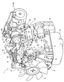
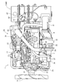
- an engine 1 as a prime mover mounted on a work machine such as an agricultural machine or a construction / civil engineering machine has a continuously regenerative exhaust gas purifying device 2 (diesel particulate filter, hereinafter referred to as DPF). ).
- DPF diesel particulate filter
- the particulate matter (PM) in the exhaust gas discharged from the engine 1 is removed by the DPF 2 and carbon monoxide (CO) and hydrocarbons (HC) in the exhaust gas are reduced.
- the engine 1 includes a cylinder block 4 that incorporates a crankshaft 3 that is an engine output shaft and a piston (not shown).
- a cylinder head 5 is mounted on the cylinder block 4.
- An intake manifold 6 is disposed on the right side surface of the cylinder head 5, and an exhaust manifold 7 is disposed on the left side surface of the cylinder head 5.
- the upper surface side of the cylinder head 5 is covered with a head cover 8.
- the front and rear end sides of the crankshaft 3 are projected from both front and rear side surfaces of the cylinder block 4.
- a cooling fan 9 is provided on the front side of the engine 1. Rotational power is transmitted from the front end side of the crankshaft 3 to the cooling fan 9 via the cooling fan V-belt 22.
- a flywheel housing 10 is provided on the rear side of the engine 1.
- a flywheel 11 is accommodated in the flywheel housing 10 in a state of being supported on the rear end side of the crankshaft 3.
- the rotational power of the engine 1 is transmitted from the crankshaft 3 to the operating part of the work machine via the flywheel 11.
- An oil pan 12 that stores lubricating oil is disposed on the lower surface of the cylinder block 4.
- the lubricating oil in the oil pan 12 is supplied to each lubricating portion of the engine 1 through the oil filter 13 and the like disposed on the right side surface of the cylinder block 4, and then returns to the oil pan 12.
- a fuel supply pump 14 is provided on the right side of the cylinder block 4 above the oil filter 13 (below the intake manifold 6).
- the engine 1 includes an injector 15 for four cylinders having an electromagnetic opening / closing control type fuel injection valve (not shown).
- Each injector 15 is connected to a fuel tank (not shown) mounted on the work machine via a fuel supply pump 14, a cylindrical common rail 16 (pressure accumulation chamber), and a fuel filter 17. Fuel in the fuel tank is pumped from the fuel supply pump 14 to the common rail 16 via the fuel filter 17, and high-pressure fuel is stored in the common rail 16.
- By controlling opening and closing of the fuel injection valve of each injector 15 high-pressure fuel in the common rail 16 is injected from each injector 15 to each cylinder of the engine 1.
- the cooling water pump 21 for cooling water lubrication is disposed coaxially with the fan shaft of the cooling fan 9 on the front side of the cylinder block 4.
- the cooling water pump 21 is driven together with the cooling fan 9 via the cooling fan V-belt 22 by the rotational power of the crankshaft 3.
- Cooling water in a radiator (not shown) mounted on the work machine is supplied to the cylinder block 4 and the cylinder head 5 by driving the cooling water pump 21 to cool the engine 1.
- the cooling water that has contributed to the cooling of the engine 1 is returned to the radiator.
- An alternator 23 is arranged on the left side of the cooling water pump 21.
- the engine leg mounting portions 24 are respectively provided on the left and right side surfaces of the cylinder block 4. Each engine leg mounting portion 24 is bolted to an engine leg (not shown) having vibration-proof rubber. The engine 1 is supported in a vibration-proof manner on a work machine (specifically, an engine mounting chassis) through each engine leg.
- the inlet portion of the intake manifold 6 is connected to an air cleaner (not shown) via an EGR device 26 (exhaust gas recirculation device).
- the fresh air (external air) sucked into the air cleaner is dust-removed and purified by the air cleaner, then sent to the intake manifold 6 via the EGR device 26 and supplied to each cylinder of the engine 1.
- the EGR device 26 mixes a part of the exhaust gas of the engine 1 (EGR gas from the exhaust manifold 7) and fresh air (external air from the air cleaner) and supplies them to the intake manifold 6;
- the EGR body case 27 is connected to the recirculation exhaust gas pipe 30, the recirculation exhaust gas pipe 30 connected to the exhaust manifold 7 via the EGR cooler 29, and the recirculation exhaust gas pipe 30.
- EGR valve member 31 is provided.
- An intake throttle member 28 is connected to the intake manifold 6 via an EGR main body case 27.
- the intake throttle member 28 is bolted to one end of the EGR main body case 27 in the longitudinal direction.
- the left and right inwardly opening end portions of the EGR main body case 27 are bolted to the inlet portion of the intake manifold 6.
- An outlet side of the recirculated exhaust gas pipe 30 is connected to the EGR main body case 27 via an EGR valve member 31.
- the inlet side of the recirculated exhaust gas pipe 30 is connected to the lower surface side of the exhaust manifold 7 via the EGR cooler 29.
- the amount of EGR gas supplied to the EGR main body case 27 is adjusted by adjusting the opening of an EGR valve (not shown) in the EGR valve member 31.
- fresh air is supplied from the air cleaner through the intake throttle member 28 into the EGR main body case 27, while EGR is supplied from the exhaust manifold 7 through the EGR valve member 31 into the EGR main body case 27.
- Gas (a part of the exhaust gas discharged from the exhaust manifold 7) is supplied. After fresh air from the air cleaner and EGR gas from the exhaust manifold 7 are mixed in the EGR main body case 27, the mixed gas in the EGR main body case 27 is supplied to the intake manifold 6.
- a turbocharger 32 is arranged on the right side of the cylinder head 5 and above the exhaust manifold 7.
- the turbocharger 32 includes a turbine case 33 with a built-in turbine wheel (not shown) and a compressor case 34 with a blower foil (not shown).
- the exhaust inlet side of the turbine case 33 is connected to the outlet portion of the exhaust manifold 7.
- the exhaust outlet side of the turbine case 33 is connected to a tail pipe (not shown) via the DPF 2.
- Exhaust gas discharged from each cylinder of the engine 1 to the exhaust manifold 7 is discharged to the outside through the turbine case 33 of the turbocharger 32, the DPF 2, and the like.
- the intake inlet side of the compressor case 34 is connected to an air cleaner via an intake pipe 35.
- An intake outlet side of the compressor case 34 is connected to an intake throttle member 28 via a supercharging pipe 36.
- the fresh air removed by the air cleaner is sent from the compressor case 34 to the intake manifold 6 via the intake throttle member 28 and the EGR main body case 27 and supplied to each cylinder of the engine 1.
- the intake pipe 35 is connected to a breather chamber 38 in the head cover 8 via a blow-by gas return pipe 37 (see FIG. 7).
- the blow-by gas from which the lubricating oil is separated and removed in the breather chamber 38 is returned to the intake pipe 35 through the blow-by gas return pipe 37, is returned to the intake manifold 6, and is supplied again to each cylinder of the engine 1.
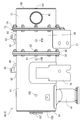
- the DPF 2 includes a purification casing 40 made of a heat-resistant metal material having a purification inlet pipe 41 and a purification outlet pipe 42. Inside the purification casing 40 is a diesel oxidation catalyst 43 such as platinum that generates nitrogen dioxide (NO 2 ), and a honeycomb-structured soot that continuously oxidizes and removes the collected particulate matter (PM) at a relatively low temperature.
- a filter 44 is accommodated in series in the exhaust gas movement direction (see the arrow direction in FIG. 9).
- a purification inlet pipe 41 and a purification outlet pipe 42 are provided separately on both sides in the longitudinal direction (one end side and the other end side) of the purification casing 40.
- the purification inlet pipe 41 is connected to the exhaust outlet side of the turbine case 33.
- the purification outlet pipe 42 is connected to a tail pipe (not shown).
- the exhaust gas of the engine 1 flows into the purification casing 40 from the exhaust outlet side of the turbine case 33 via the purification inlet pipe 41 and passes through the diesel oxidation catalyst 43 and the soot filter 44 in this order for purification. It is processed. Particulate matter in the exhaust gas is collected without passing through the porous partition wall between the cells in the soot filter 44. Thereafter, exhaust gas that has passed through the diesel oxidation catalyst 43 and the soot filter 44 is discharged toward the tail pipe.
- the exhaust gas passes through the diesel oxidation catalyst 43 and the soot filter 44, if the exhaust gas temperature exceeds a renewable temperature (for example, about 300 ° C.), the oxidation of the exhaust gas is caused by the action of the diesel oxidation catalyst 43.
- Nitrogen (NO) is oxidized to unstable nitrogen dioxide.
- oxygen (O) released when nitrogen dioxide returns to nitric oxide oxidizes and removes the particulate matter deposited on the soot filter 44, so that the particulate matter collecting ability of the soot filter 44 is recovered (soot).
- the filter 44 self-regenerates).
- the other end side in the longitudinal direction of the purification casing 40 is configured in the silencer 45, and the purification outlet pipe 42 is provided in the silencer 45.
- the diesel oxidation catalyst 43 and the soot filter 44 correspond to a filter body for exhaust gas purification.
- the purification casing 40 includes a catalyst inner case 46 and a catalyst outer case 47, a filter inner case 48 and a filter outer case 49, a sound deadening inner case 50 and a sound deadening outer case 51.
- the combination of each of the inner cases 46, 48, 50 and the outer cases 47, 49, 51 has a double cylinder structure.
- a diesel oxidation catalyst 43 is accommodated in the catalyst inner case 46.
- the soot filter 44 is accommodated in the filter inner case 48.
- a thin plate support 52 having an L-shaped cross section is disposed between the outer peripheral side of the catalyst inner case 46 and the inner peripheral side of the catalyst outer case 47.
- the outer peripheral side of the catalyst inner case 46 and the inner peripheral side of the catalyst outer case 47 are connected via a thin plate support 52.
- the combination of the inner cases 46 and 48 and the outer cases 47 and 49 corresponds to a purification case that is a component of the purification casing 40.
- the DPF 2 of the embodiment includes the silencer 45, but the silencer 45 itself is not an essential component of the DPF 2. That is, the silencer inner case 50 and the silencer outer case 51 are not essential components of the purification casing 40.
- a catalyst inner lid body 53 is welded and fixed to one end side (end portion on the exhaust upstream side) of the catalyst inner case 46 and the catalyst outer case 47. One end sides of the catalyst inner case 46 and the catalyst outer case 47 are closed by a catalyst inner lid 53.
- a catalyst outer lid body 54 that covers the catalyst inner lid body 53 from the outside is welded and fixed to the outer end face side of the catalyst inner lid body 53.
- a purification inlet pipe 41 is welded and fixed to the outer peripheral side of the catalyst outer case 47. The purification inlet pipe 41 communicates with the catalyst inner case 46 via an exhaust gas inlet 55 formed in the catalyst inner case 46 and the catalyst outer case 47.
- a thin plate-like catalyst flange 56 protruding from the outer peripheral side (radius outer side) of the catalyst outer case 47 is welded and fixed to the other end side (end portion on the exhaust downstream side) of the catalyst inner case 46.
- the other end side of the catalyst outer case 47 is welded and fixed to the outer peripheral side of the catalyst flange 56.
- a thin plate-like filter inlet flange 57 that protrudes from the outer peripheral side of the filter outer case 49 is welded and fixed to a longitudinal middle part of the outer peripheral side of the filter inner case 48.
- One end side (end portion on the upstream side of the exhaust) of the filter outer case 49 is fixed by welding to the outer peripheral side of the filter inlet flange 57.
- the catalyst flange 56 and the filter inlet flange 57 are brought into contact with each other through the gasket 58, and both are sandwiched by thick plate-like central clamping flanges 59 and 60 surrounding the outer peripheral sides of the outer cases 47 and 49.
- the flanges 56 and 57 are clamped from both sides in the exhaust gas movement direction, and both the central clamp flanges 59 and 60 are fastened together with both the flanges 56 and 57 with bolts 61 and nuts 62, so that the catalyst outer case 47 and the filter outer case 49 Are concatenated.
- one end side of the filter inner case 46 overlaps (inserts) from the other end side of the catalyst inner case 46 and the catalyst outer case 47. ).
- the silencer 45 located on the other end side in the longitudinal direction of the purification casing 40 includes a silencer inner case 50 and a silencer outer case 51 having a double cylinder structure.
- a partition lid 63 is welded and fixed to one end side (end portion on the exhaust upstream side) of the silencer inner case 50.
- One end side of the silencer inner case 50 is closed by a partition lid 63.
- a silencer inner lid body 64 is welded and fixed to the other end side (end portion on the exhaust downstream side) of the silencer inner case 50 and the silencer outer case 51.
- a silencer outer lid body 65 that covers the silencer inner lid body 64 from the outside is welded and fixed.
- a pair of communication pipes 66 is provided between the partition lid 63 and the muffler inner lid 64 (only one is shown in FIG. 9). One end side of both communication pipes 66 penetrates the partition lid 63. The other end side of both the communication pipes 66 is closed by a sound deadening inner lid body 64. A number of communication holes 67 are formed in each communication pipe 66.
- the inside of the silencer inner case 50 partitioned by the partition lid 63 and the silencer inner lid 64 is configured as a resonance chamber that communicates with both the communication pipes 66 through the communication holes 67.
- the silencing inner case 50 and the silencing outer case 51 are penetrated by a purification outlet pipe 42 passing between the two communicating pipes 66.
- a pair of outlet lid bodies 68 are welded and fixed to one end side (upper end side) of the purification outlet pipe 42.
- One end side of the purification outlet pipe 42 is closed by both outlet lid bodies 68.
- Both outlet lids 68 are arranged at an appropriate interval in the vertical direction.
- a number of exhaust holes 69 are formed in a portion of the purification outlet pipe 42 in the silencer inner case 50. Accordingly, both communication pipes 66 in the muffler inner case 50 communicate with the purification outlet pipe 42 via the communication holes 67, the resonance chambers and the exhaust holes 69.
- the other end side (lower end side) of the purification outlet pipe 42 is connected to, for example, a tail pipe or an existing silencing member.
- the exhaust gas that has entered the both communication pipes 66 of the muffler inner case 46 passes through the purification outlet pipe 42 via the communication hole 67, the resonance chamber and the exhaust hole 69, and is discharged out of the silencer 45.
- a thin plate-like filter outlet flange 70 protruding from the outer peripheral side of the filter outer case 49 is fixed to the other end of the filter inner case 48 by welding.
- the other end side of the filter outer case 49 is fixed to the outer peripheral side of the filter outlet flange 70 by welding.
- a thin plate-like silencing flange 71 protruding from the outer peripheral side of the silencing outer case 51 is welded and fixed to one end of the silencing inner case 50.
- One end side of the silencer outer case 51 is welded and fixed to the outer peripheral side of the silencer flange 71.
- the filter outlet flange 70 and the silencing flange 71 are brought into contact with each other through a gasket 72, and both are connected by thick plate-like outlet clamping flanges 73 and 74 surrounding the outer peripheral sides of the outer cases 49 and 51.
- the flanges 70 and 71 are clamped from both sides in the exhaust gas movement direction, and both the outlet clamping flanges 73 and 74 are fastened together with both the flanges 70 and 71 by bolts 75 and nuts 76.
- Each center clamping flange 59 is composed of arcuate bodies 59a and 59b (60a and 60b) divided into a plurality of portions in the circumferential direction of the corresponding outer case 47 (49).
- Each arc body 59a, 59b (60a, 60b) is formed in an arc shape (substantially semicircular horseshoe shape).
- the ends of both arcs 59a, 59b (60a, 60b) face each other in the circumferential direction, and the catalyst outer case 47 (filter outer case 49).
- the abutting portions of the ends of the arcuate bodies 59a and 59b on the catalyst side and the arcuate bodies 60a and 60b on the filter inlet side are placed at positions shifted from each other (the abutting portions are overlapped in the same phase). Absent).
- Each of the circular arc bodies 59a, 59b, 60a, 60b constituting the central clamping flanges 59, 60 has the same form.
- Each outlet pinching flange 73 (74) is also composed of arcuate bodies 73a and 73b (74a and 74b) divided into a plurality of portions in the circumferential direction of the corresponding outer case 49 (51), like the central pinching flanges 59 and 60. Yes.
- the arc bodies 73a and 73b (74a and 74b) have basically the same form as the arc bodies 59a and 59b (60a and 60b) of the center clamping flange 59 (60).
- the abutting portions between the ends of the arcuate bodies 73a and 73b on the filter outlet side and the arcuate bodies 74a and 74b on the silencing side are also placed at positions that are out of phase with each other.
- a connecting leg 77 for supporting the purification casing 40 on the engine 1 is detachably attached to at least one of the sandwiching flanges 59, 60, 73, 74.
- a leg fastening portion 78 with a through hole is formed in one arcuate body 73 a of the outlet pinching flange 73.
- An attachment boss portion corresponding to the leg fastening portion 78 of the arc member 73a is formed on the connecting leg 77.
- the connecting leg 77 is detachably attached to the outlet holding flange 73 on the filter outlet side by bolting the mounting boss portion of the connecting leg 77 to the leg fastening portion 78 of the arc member 73a.
- a fixed leg 79 for supporting the purification casing 40 on the engine 1 is fixed to the outer peripheral side of the purification casing 40 (in the embodiment, the catalyst outer case 47) by welding.
- the connecting leg 77 and the fixed leg 79 are bolted to a DPF attachment portion 80 formed on the upper surface side of the flywheel housing 10. That is, the DPF 2 is stably connected and supported on the flywheel housing 10, which is a highly rigid member, by the connecting legs 77 and the fixed legs 79.
- an exhaust gas pressure sensor 81 for detecting the exhaust gas pressure in the purification casing 40 and an exhaust gas for detecting the exhaust gas temperature in the purification casing 40 are disposed on the outer peripheral side of the purification casing 40.
- the exhaust gas pressure sensor 81 detects the pressure difference of the exhaust gas between the exhaust upstream side and the exhaust downstream side across the soot filter 44. Based on the pressure difference, the amount of particulate matter deposited on the soot filter 44 is converted, and the clogged state in the DPF 2 is grasped.
- a substantially L-shaped sensor bracket 83 that supports the exhaust gas pressure sensor 81 and the exhaust gas temperature sensor 82 is detachably attached to at least one of the sandwiching flanges 59, 60, 73, and 74.
- a sensor support portion 86 with a through hole is formed in one arcuate body 74 a of the outlet clamping flange 74 on the silencer side. That is, the sensor support portion 86 is formed in a part of the muffler-side outlet pinching flange 74 farthest from the exhaust gas inlet 55 side.
- the sensor bracket 83 is detachably attached to the mute-side outlet pinching flange 74 by bolting the vertical plate portion 85 of the sensor bracket 83 to the sensor support portion 86 of the arcuate body 43a.
- the sensor support 86 of the arcuate body 74a projects to the outer peripheral side (radius outside) of the purification casing 40.
- the horizontal plate portion 84 of the sensor bracket 83 is separated outward from the outer peripheral side of the purification casing 40.
- the exhaust gas pressure sensor 81 and the exhaust gas temperature sensor 82 are juxtaposed on the horizontal plate portion 84 of the sensor bracket 83.
- the horizontal plate portion 84 of the sensor bracket 83 is located on the outer peripheral side of the filter outer case 49 so that the sensors 81 and 82 are within the length range of the purification casing 40 in the exhaust gas movement direction. If such a mounting structure is adopted, even if the silencer 45 is not directly attached to the DPF 2, both the sensors 81 and 82 can be accommodated within the length range of the purification casing 40 in the exhaust gas movement direction.
- the exhaust gas pressure sensor 81 is integrally provided with a pressure wiring connector 87.
- the exhaust gas pressure sensor 81 is connected to the proximal end sides of the upstream and downstream pipe joint bodies 90 and 91 via upstream and downstream sensor pipes 88 and 89, respectively.
- a pressure boss body 92 is fixed to the catalyst inner case 46 and the filter inner case 48 by welding so as to sandwich the soot filter 44 therebetween.
- the outward protruding end side of each pressure boss body 92 protrudes radially outward from the opening formed in the corresponding outer case 47, 49.
- the distal ends of the pipe joint bodies 90 and 91 are fastened to the corresponding pressure boss bodies 92 via pipe joint bolts 93, respectively.
- the exhaust gas temperature sensor 82 includes a temperature wiring connector 94 on the horizontal plate portion 84 of the sensor bracket 83. Three sensor pipes 95 to 97 extend from the exhaust gas temperature sensor 82 (which may be referred to as a temperature wiring connector 94).
- a temperature boss body 98 is fixed to the catalyst inner case 46 and the filter inner case 48 by welding. Two temperature bosses 98 are provided in the catalyst inner case 46, and one temperature boss body 98 is provided in the filter inner case 48. The outward protruding end side of each temperature boss body 98 protrudes radially outward from the opening formed in the corresponding outer case 47, 49.
- a detection portion at the tip of sensor pipes 95 to 97 extending from the exhaust gas temperature sensor 82 is passed through a mounting bolt 99 screwed to each temperature boss body 98, and the sensor pipe 95 is connected to the temperature boss body 98 via the mounting bolt 99.
- the detection part at the tip of ⁇ 97 is fixed.
- the detection portions at the tips of the sensor pipes 95 to 97 are between the catalyst inner lid 53 and the diesel oxidation catalyst 43, between the diesel oxidation catalyst 43 and the soot filter 44, and between the soot filter 44 and the partition lid 63. Each rushes in between.
- the exhaust gas pressure sensor 81 and the exhaust gas temperature sensor 82 are placed on the horizontal plate portion 84 of the sensor bracket 83 with the connection direction of the pressure wiring connector 87 and the temperature wiring connector 94 being in the same direction. It is fixed. For this reason, the connection workability of the wiring with respect to each connector 87,94 can be improved.
- the suspension body 101 is integrally formed on the other arcuate body 73b of the outlet holding flange 73 on the filter outlet side, and the suspension fitting 102 is bolted to the catalyst outer lid body 54 of the purification casing 40. It is concluded.
- the suspension body 101 and the suspension fitting 102 are opposed to each other in the exhaust gas movement direction so that the respective opening holes 103 and 104 are located in the diagonal direction of the purification casing 40 (direction intersecting the longitudinal axis A). (See FIG. 11).
- the suspended body 101 may be integrally formed with the other holding flanges 59, 60, and 74.
- the suspension body 101 and the suspension metal fitting 102 are locked to the hook (not shown) of the chain block, and the purification casing 40 is moved up and down by the chain block.
- the purification casing 40 can be assembled to the casing. That is, the purification casing 40 can be smoothly mounted on the engine 1 by using the suspended body 101 and the suspension fitting 102 without the operator lifting the purification casing 40 by himself / herself.
- the purification casing 40 which is a heavy object, can be suspended in a stable posture by the positional relationship in the diagonal direction between the suspended body 101 and the suspended metal fitting 102.
- the DPF attachment portion 80 of the flywheel housing 10 and the connecting leg body 77 and the fixed leg 79 can be easily aligned. Therefore, the assembly workability of the DPF 2 can be improved.
- each clamping flange 59, 60, 73, 74 corresponding to a thick plate flange is provided with a plurality of bolt fastening portions 105 with through holes at equal intervals along the circumferential direction.
- ten bolt fastening portions 105 are provided for each pair of clamping flanges 59, 60, 73 and 74.
- five bolt fastening portions 105 are provided at equal intervals along the circumferential direction.
- Bolt holes 106 corresponding to the respective bolt fastening portions 105 of the clamping flanges 59, 60, 73, 74 are formed in the flanges 56, 57, 70, 71.
- the mounting phase of the arcuate bodies 59a, 59b, 60a, 60b, 73a, 73b, 74a, 74b of the holding flanges 59, 60, 73, 74 is around the longitudinal axis A in the exhaust gas movement direction of the purification casing 40. It can be changed in multiple stages (along the circumferential direction of the purification casing 40).
- the lid that closes both ends of the purification casing 40 in the exhaust gas movement direction has a double structure of the inner lids 53 and 64 and the outer lids 54 and 65. . And the water which accumulates between the inner cover bodies 53 and 64 and the outer cover bodies 54 and 65 is discharged
- a first drain hole 107 is formed (see FIGS. 7 to 11).
- the outer lid bodies 54 and 65 are formed in the substantially same disc shape.
- the first drain hole 107 is formed in the peripheral edge in the radial direction with respect to the center line (longitudinal axis A) in the exhaust gas movement direction in each of the outer lid bodies 54 and 65.
- the first drain hole 107 of the embodiment opens at the peripheral edge in the cross direction when viewed from the center line (longitudinal axis A) in the exhaust gas movement direction (four to one outer lid body 54, 65). Some places are open).
- the inner lid bodies 53 and 64 and the outer lid bodies 54 and 65 communicate with the outside through the first drain holes 107.
- cleaning casing 40 will be plugged up with the double structure of the inner cover bodies 53 and 64 and the outer cover bodies 54 and 65, and heat insulation will be carried out.
- the water collected between the inner lid bodies 53 and 64 and the outer lid bodies 54 and 65 due to condensation, rain water, etc. can be discharged from the first drain hole 107, and the drainage of the DPF 2 is improved. .
- the corrosion resistance performance of DPF2 improves.
- both ends of the purification casing 40 in the exhaust gas movement direction are closed by the outer lid bodies 54 and 65 having the same shape, it is possible to reduce the number of components and contribute to cost reduction.
- the direction of attachment around the center line (longitudinal axis A) of the outer lid bodies 54 and 65 is adjusted with respect to each end of the purification casing 40 in the exhaust gas movement direction. Easy to change. As a result, the degree of freedom of the mounting direction of the outer case (for example, the catalyst outer case 47 and the muffler outer case 51) with respect to the engine 1 can be increased.
- the outer cases 47 and 49 are located at least in the lower part and are collected between the inner cases 46 and 48 and the outer cases 47 and 49.
- a second drain hole 108 for discharging water is formed.
- second drain holes 108 are formed at three locations of the catalyst outer case 47 on both sides of the fixed leg 79 and the filter outer case 49. If comprised in this way, although the purification
- a purification casing comprising a plurality of filter bodies 43, 44 for purifying exhaust gas discharged from the engine 1 and a plurality of purification cases 46-49 containing the filter bodies 43, 44 therein. 40, an exhaust gas pressure sensor 81 for detecting the exhaust gas pressure in the purification casing 40, and an exhaust gas temperature sensor 82 for detecting the exhaust gas temperature in the purification casing 40. Since the two sensors 81 and 82 are arranged on the outer peripheral side of the purification casing 40 so as to be within the length range of the purification casing 40 in the exhaust gas movement direction, it is determined for each specification of the engine 1 and each work machine.
- the exhaust gas purification device 2 can be standardized. Since the mounting positions of the sensors 81 and 82 are within the length range of the purification casing 40 in the exhaust gas movement direction, the purification casing 40 (the exhaust gas purification device 2) has a total length in the exhaust gas movement direction. The influence of both the sensors 81 and 82 can be eliminated. As a result, the exhaust gas purification device 2 including both the sensors 81 and 82 can be compactly arranged in the arrangement space of the engine 1.
- a sensor bracket 83 is detachably attached to a sensor support portion 86 provided in a part of the flanges 59, 60, 73, 74 of the purification cases 46 to 49, and both sensors are attached to the sensor bracket 83. Since 81 and 82 are provided, both the sensors 81 and 82 are supported by the highly rigid flanges 59, 60, 73 and 74, and vibrations transmitted to both the sensors 81 and 82 can be reduced. For this reason, an adverse effect on the detection accuracy of the sensors 81 and 82 can be suppressed. The sensors 81 and 82 can be prevented from falling off.
- the sensor support portion 86 is formed in a part of the flange 74 farthest from the exhaust gas inlet 55 side in the purification cases 46 to 49, and the horizontal plate portion 84 of the sensor bracket 83 is the purification casing 40. Since the both sensors 81 and 82 are arranged in parallel on the horizontal plate portion 84, the heat generated by the exhaust gas purifying device 2 is the two sensors 81 and 82. It is hard to be transmitted to. For this reason, although both said sensors 81 and 82 are assembled
- the lengths of the sensor pipes 88, 89, and 95 to 97 that connect the exhaust gas purification device 2 and the sensors 81 and 82 are long.
- the length can be set short, and the assembly workability can be improved and the cost can be reduced.
- the purification cases 47, 49, 51 are arranged in the exhaust gas moving direction on the thick plate flanges 59, 60, 73, 74.
- the purification casing 40 is configured by connecting the suspension plate 101 and the suspension body 101 is integrally formed with the thick plate flange 73.
- the hook of the chain block The suspension body 101 and the suspension fitting 102 are engaged with (not shown), and the purification case is separated by the chain block. It raises and lowers the grayed 40 may assembling the purification casing 40 to the engine 1. That is, the purification casing 40 can be smoothly mounted on the engine 1 using the suspension body 101 and the suspension fitting 102 without the operator lifting the purification casing 40 by himself.
- the suspension body 101 is disposed on one end side of the purification casing 40 in the exhaust gas movement direction, and is suspended on the other end side of the purification casing 40 in the exhaust gas movement direction.
- a metal fitting 102 is arranged, and the suspension body 101 and the metal fitting 102 are arranged so that the respective opening holes 103 and 104 are located in the direction intersecting the longitudinal axis A of the purification casing 40 in the exhaust gas movement direction.
- the purification casing 40 which is a heavy object, has a stable posture according to the positional relationship in the diagonal direction between the suspension body 101 and the suspension fitting 102.
- the position of the DPF mounting portion 80 of the flywheel housing 10 with the connecting leg 77 and the fixed leg 79 can be adjusted. The performed easily. Therefore, the assembly workability of the exhaust gas purification device 2 can be improved.
- the attachment angle of the thick plate flanges 59, 60, 73, 74 can be changed around the longitudinal axis A in the exhaust gas movement direction of the purification casing 40. Therefore, the connecting direction of the purification inlet pipe 41 and the purification outlet pipe 42 (the engine 1) without changing the shape of the thick plate flanges 59, 60, 73, 74 (the position where the suspended body 101 is formed).
- the position of the suspended body 101 can be easily changed with respect to the mounting specification of the exhaust gas purification device 2), and it is possible to contribute to further improvement of the assembly workability of the exhaust gas purification device 2.
- the lids that close both ends of the purification casing 40 in the exhaust gas movement direction are the inner lid bodies 53, 64 and the outer lid bodies 54, 65.
- the inner lid is formed in a double structure and is located at least at the lower part of the outer lid bodies 54 and 65 in a state where the purification casing 40 is mounted on the engine 1. Since the first drain holes 107 for discharging water accumulated between the outer lid bodies 54 and 56 are formed, both ends of the purification casing 40 in the exhaust gas movement direction are connected to the inner lid.
- the inner lid bodies 53 and 64 and the outer lid bodies 54 and 65 are sealed by a double structure of the bodies 53 and 64 and the outer lid bodies 54 and 65 so as to ensure heat insulation. Can be discharged from the first drain hole 107, so that the drainage of the exhaust gas purification device 2 is improved. For this reason, the corrosion resistance performance of the exhaust gas purification device 2 is improved.
- the purification casing 40 since the first drain hole 107 is formed at a radial position with respect to the center line (longitudinal axis A) in the exhaust gas movement direction in the outer lid bodies 54 and 65, the purification casing 40. It is possible to close both ends in the exhaust gas movement direction with the outer lid bodies 54 and 65 having the same shape. For this reason, it can contribute to cost reduction by reducing the number of components. Moreover, the center line (longitudinal axis A) of the outer lid bodies 54 and 65 with respect to each end of the purification casing 40 in the exhaust gas movement direction without changing the shape of the outer lid bodies 54 and 65. You can easily change the direction of mounting around. As a result, the degree of freedom of the mounting direction of the outer case (for example, the catalyst outer case 47 and the silencer outer case 51) with respect to the engine 1 can be increased.
- the purification casing 40 in a state where the purification casing 40 is mounted on the engine 1, it accumulates between the inner cases 46 and 48 and the outer cases 47 and 49 at a position located at least in the lower case 47 and 49. Since the second drain hole 108 for discharging water is formed, the purification casing 40 is configured in a double structure of the inner cases 46 and 48 and the outer cases 47 and 49 to ensure heat insulation. However, water accumulated between the inner cases 46 and 48 and the outer cases 47 and 49 due to condensation, rain water, or the like can be discharged from the second drain hole 108, and the exhaust gas purifier 2 can be drained. Sexuality is improved. For this reason, it can contribute to the further improvement of the corrosion resistance performance of the exhaust gas purification device 2.
- this invention is not limited to the above-mentioned embodiment, It can be embodied in various aspects.
- the structure of each part in this invention is not limited to embodiment of illustration, A various change is possible in the range which does not deviate from the meaning of this invention.
Landscapes
- Engineering & Computer Science (AREA)
- Chemical & Material Sciences (AREA)
- Combustion & Propulsion (AREA)
- Mechanical Engineering (AREA)
- General Engineering & Computer Science (AREA)
- Chemical Kinetics & Catalysis (AREA)
- Health & Medical Sciences (AREA)
- Toxicology (AREA)
- Materials Engineering (AREA)
- Analytical Chemistry (AREA)
- Processes For Solid Components From Exhaust (AREA)
- Exhaust Gas After Treatment (AREA)
Description
はじめに、図1~図6を参照しながら、コモンレール式のエンジン1の概略構造について説明する。なお、以下の説明では、クランク軸線と平行な両側部(クランク軸線を挟んで両側の側部)を左右、冷却ファン9配置側を前側、フライホイルハウジング10配置側を後側と、排気マニホールド7配置側を左側、吸気マニホールド6配置側を右側と称して、これらを便宜的に、エンジン1における四方及び上下の位置関係の基準としている。
次に、図7~図10を参照しながら、DPF2の概略構造について説明する。DPF2は、浄化入口管41及び浄化出口管42を有する耐熱金属材料製の浄化ケーシング40を備えている。浄化ケーシング40の内部には、二酸化窒素(NO2)を生成する白金等のディーゼル酸化触媒43と、捕集した粒子状物質(PM)を比較的低温で連続的に酸化除去するハニカム構造のスートフィルタ44とが、排気ガスの移動方向(図9の矢印方向参照)に直列に並べて収容されている。浄化ケーシング40の長手方向両側(一端側と他端側)に、浄化入口管41と浄化出口管42とが振り分けて設けられている。浄化入口管41はタービンケース33の排気出口側に連結されている。浄化出口管42はテールパイプ(図示省略)に連結されている。
以上の構成から明らかなように、エンジン1が排出した排気ガスを浄化する複数のフィルタ体43,44と、前記各フィルタ体43,44を内蔵する複数の浄化ケース46~49からなる浄化ケーシング40と、前記浄化ケーシング40内の排気ガス圧力を検出する排気ガス圧力センサ81と、前記浄化ケーシング40内の排気ガス温度を検出する排気ガス温度センサ82とを備えている排気ガス浄化装置2において、前記浄化ケーシング40の外周側に、前記両センサ81,82が前記浄化ケーシング40の排気ガス移動方向の長さ範囲内に収まるように配置されているから、エンジン1の仕様毎や作業機械毎に前記各センサ81,82の初期設定(調整)の適否を評価する必要がなく、設計・試験等の評価工数を削減できる。前記排気ガス浄化装置2関連の構成部品の標準化を図れる。前記両センサ81,82の取付け位置が前記浄化ケーシング40の排気ガス移動方向の長さ範囲内に収まるから、前記浄化ケーシング40(前記排気ガス浄化装置2)の排気ガス移動方向の全長に対して前記両センサ81,82の影響をなくせる。その結果、エンジン1の配置スペース内に、前記両センサ81,82を含む前記排気ガス浄化装置2をコンパクトに配置できる。
2 DPF(排気ガス浄化装置)
40 浄化ケーシング
41 浄化入口管
42 浄化出口管
43 ディーゼル酸化触媒
44 スートフィルタ
46 触媒内側ケース
47 触媒外側ケース
48 フィルタ内側ケース
49 フィルタ外側ケース
55 排気ガス入口
56 触媒フランジ
57 フィルタ入口フランジ
59,60 中央挟持フランジ
70 フィルタ出口フランジ
71 消音フランジ
73,74 出口挟持フランジ
81 排気ガス圧力センサ
82 排気ガス温度センサ
83 センサブラケット
84 水平板部
86 センサ支持部
107 第1水抜き穴
108 第2水抜き穴
Claims (6)
- エンジンが排出した排気ガスを浄化する複数のフィルタ体と、前記各フィルタ体を内蔵する複数の浄化ケースからなる浄化ケーシングと、前記浄化ケーシング内の排気ガス圧力を検出する排気ガス圧力センサと、前記浄化ケーシング内の排気ガス温度を検出する排気ガス温度センサとを備えている排気ガス浄化装置において、
前記浄化ケーシングの外周側に、前記両センサが前記浄化ケーシングの排気ガス移動方向の長さ範囲内に収まるように配置されている、
排気ガス浄化装置。 - 前記浄化ケース群のフランジの一部に設けたセンサ支持部に、センサブラケットが着脱可能に取り付けられており、前記センサブラケットに前記両センサが設けられている、
請求項1に記載した排気ガス浄化装置。 - 前記センサ支持部は、前記浄化ケース群において排気ガス入口側から最も遠いフランジの一部に形成されており、前記センサブラケットの水平板部が前記浄化ケーシングの外周側から外向きに離れた位置にあり、前記水平板部上に前記両センサが並設されている、
請求項2に記載した排気ガス浄化装置。 - 前記各フィルタ体を内蔵する複数の内側ケースと、前記各内側ケースを内蔵する複数の外側ケースとを備えており、前記各外側ケースを排気ガス移動方向に並べて連結することによって、前記浄化ケーシングを形成している構造であって、
前記浄化ケーシングの排気ガス移動方向の両端部を塞ぐ蓋体は、内蓋体と外蓋体との二重構造に構成されており、前記浄化ケーシングを前記エンジンに搭載した状態で前記外蓋体において少なくとも下部に位置する箇所に、前記内蓋体と前記外蓋体との間に溜まる水を排出させる第1水抜き穴が形成されている、
請求項1~3のうちいずれかに記載した排気ガス浄化装置。 - 前記第1水抜き穴は、前記外蓋体において排気ガス移動方向の中心線を基準にした放射方向の位置に形成されている、
請求項4に記載した排気ガス浄化装置。 - 前記浄化ケーシングを前記エンジンに搭載した状態で、前記各外側ケースにおいて少なくとも下部に位置する箇所に、前記内側ケースと前記外側ケースとの間に溜まる水を排出させる第2水抜き穴が形成されている、
請求項4又は5に記載した排気ガス浄化装置。
Priority Applications (4)
| Application Number | Priority Date | Filing Date | Title |
|---|---|---|---|
| US14/372,390 US9103256B2 (en) | 2012-01-19 | 2013-01-08 | Exhaust emission control device |
| EP13738742.9A EP2806142B1 (en) | 2012-01-19 | 2013-01-08 | Exhaust gas purifier |
| CN201380010095.9A CN104169548A (zh) | 2012-01-19 | 2013-01-08 | 废气净化装置 |
| KR1020147020025A KR101968369B1 (ko) | 2012-01-19 | 2013-01-08 | 배기가스 정화 장치 |
Applications Claiming Priority (4)
| Application Number | Priority Date | Filing Date | Title |
|---|---|---|---|
| JP2012008947A JP5909098B2 (ja) | 2012-01-19 | 2012-01-19 | 排気ガス浄化装置 |
| JP2012008946A JP5872301B2 (ja) | 2012-01-19 | 2012-01-19 | 排気ガス浄化装置 |
| JP2012-008947 | 2012-01-19 | ||
| JP2012-008946 | 2012-01-19 |
Publications (1)
| Publication Number | Publication Date |
|---|---|
| WO2013108667A1 true WO2013108667A1 (ja) | 2013-07-25 |
Family
ID=48799095
Family Applications (1)
| Application Number | Title | Priority Date | Filing Date |
|---|---|---|---|
| PCT/JP2013/050114 Ceased WO2013108667A1 (ja) | 2012-01-19 | 2013-01-08 | 排気ガス浄化装置 |
Country Status (5)
| Country | Link |
|---|---|
| US (1) | US9103256B2 (ja) |
| EP (1) | EP2806142B1 (ja) |
| KR (1) | KR101968369B1 (ja) |
| CN (1) | CN104169548A (ja) |
| WO (1) | WO2013108667A1 (ja) |
Families Citing this family (6)
| Publication number | Priority date | Publication date | Assignee | Title |
|---|---|---|---|---|
| EP2806130B1 (en) * | 2012-01-20 | 2017-03-08 | Yanmar Co., Ltd. | Exhaust gas purification device |
| JP5491561B2 (ja) * | 2012-03-26 | 2014-05-14 | 株式会社小松製作所 | 建設機械、及び建設機械の運転動作の良否報知方法 |
| CN109854349B (zh) * | 2019-03-29 | 2024-02-27 | 三一重机有限公司 | 废气后处理装置安装结构及挖掘机 |
| KR102218524B1 (ko) * | 2020-05-21 | 2021-02-22 | 주식회사 씨엠씨텍 | 이동식 매연 저감 장치 |
| KR102909007B1 (ko) * | 2020-08-20 | 2026-01-08 | 현대자동차주식회사 | 커넥터 시스템 |
| JP2024179885A (ja) * | 2023-06-16 | 2024-12-26 | ヤンマーホールディングス株式会社 | エンジン |
Citations (11)
| Publication number | Priority date | Publication date | Assignee | Title |
|---|---|---|---|---|
| JP2001073748A (ja) | 1999-09-06 | 2001-03-21 | Hino Motors Ltd | ディーゼルエンジン排気ガス用パティキュレートフィルタのクリーニング及び再生方式及びその装置 |
| JP2004263593A (ja) | 2003-02-28 | 2004-09-24 | Calsonic Kansei Corp | ディーゼルパティキュレートフィルタ装置 |
| JP2005194949A (ja) | 2004-01-08 | 2005-07-21 | Hino Motors Ltd | 排気浄化装置 |
| WO2008136203A1 (ja) * | 2007-05-01 | 2008-11-13 | Hitachi Construction Machinery Co., Ltd. | 建設機械 |
| JP2009091982A (ja) | 2007-10-09 | 2009-04-30 | Mitsubishi Fuso Truck & Bus Corp | 排気浄化装置 |
| JP2009228516A (ja) | 2008-03-21 | 2009-10-08 | Calsonic Kansei Corp | Dpf装置 |
| JP2010007556A (ja) * | 2008-06-26 | 2010-01-14 | Komatsu Ltd | 排気ガス浄化装置 |
| JP2010043546A (ja) * | 2008-08-08 | 2010-02-25 | Komatsu Ltd | 排気ガス浄化装置 |
| JP2010043574A (ja) * | 2008-08-11 | 2010-02-25 | Hitachi Constr Mach Co Ltd | 排気ガス浄化装置 |
| JP2010144640A (ja) * | 2008-12-19 | 2010-07-01 | Yanmar Co Ltd | エンジン装置 |
| JP2011179384A (ja) * | 2010-02-26 | 2011-09-15 | Yanmar Co Ltd | 排気ガス浄化装置 |
Family Cites Families (2)
| Publication number | Priority date | Publication date | Assignee | Title |
|---|---|---|---|---|
| JP4147156B2 (ja) * | 2003-07-04 | 2008-09-10 | 日野自動車株式会社 | 排気浄化装置 |
| TW200510628A (en) * | 2003-09-10 | 2005-03-16 | O Den Corp | Particulate removing device and diesel vehicle equipped with the same |
-
2013
- 2013-01-08 US US14/372,390 patent/US9103256B2/en not_active Expired - Fee Related
- 2013-01-08 WO PCT/JP2013/050114 patent/WO2013108667A1/ja not_active Ceased
- 2013-01-08 KR KR1020147020025A patent/KR101968369B1/ko active Active
- 2013-01-08 CN CN201380010095.9A patent/CN104169548A/zh active Pending
- 2013-01-08 EP EP13738742.9A patent/EP2806142B1/en not_active Not-in-force
Patent Citations (11)
| Publication number | Priority date | Publication date | Assignee | Title |
|---|---|---|---|---|
| JP2001073748A (ja) | 1999-09-06 | 2001-03-21 | Hino Motors Ltd | ディーゼルエンジン排気ガス用パティキュレートフィルタのクリーニング及び再生方式及びその装置 |
| JP2004263593A (ja) | 2003-02-28 | 2004-09-24 | Calsonic Kansei Corp | ディーゼルパティキュレートフィルタ装置 |
| JP2005194949A (ja) | 2004-01-08 | 2005-07-21 | Hino Motors Ltd | 排気浄化装置 |
| WO2008136203A1 (ja) * | 2007-05-01 | 2008-11-13 | Hitachi Construction Machinery Co., Ltd. | 建設機械 |
| JP2009091982A (ja) | 2007-10-09 | 2009-04-30 | Mitsubishi Fuso Truck & Bus Corp | 排気浄化装置 |
| JP2009228516A (ja) | 2008-03-21 | 2009-10-08 | Calsonic Kansei Corp | Dpf装置 |
| JP2010007556A (ja) * | 2008-06-26 | 2010-01-14 | Komatsu Ltd | 排気ガス浄化装置 |
| JP2010043546A (ja) * | 2008-08-08 | 2010-02-25 | Komatsu Ltd | 排気ガス浄化装置 |
| JP2010043574A (ja) * | 2008-08-11 | 2010-02-25 | Hitachi Constr Mach Co Ltd | 排気ガス浄化装置 |
| JP2010144640A (ja) * | 2008-12-19 | 2010-07-01 | Yanmar Co Ltd | エンジン装置 |
| JP2011179384A (ja) * | 2010-02-26 | 2011-09-15 | Yanmar Co Ltd | 排気ガス浄化装置 |
Non-Patent Citations (1)
| Title |
|---|
| See also references of EP2806142A4 |
Also Published As
| Publication number | Publication date |
|---|---|
| EP2806142A1 (en) | 2014-11-26 |
| US9103256B2 (en) | 2015-08-11 |
| EP2806142A4 (en) | 2015-09-23 |
| CN104169548A (zh) | 2014-11-26 |
| EP2806142B1 (en) | 2017-12-13 |
| US20140352282A1 (en) | 2014-12-04 |
| KR101968369B1 (ko) | 2019-04-11 |
| KR20140120889A (ko) | 2014-10-14 |
Similar Documents
| Publication | Publication Date | Title |
|---|---|---|
| KR101946095B1 (ko) | 배기가스 정화 장치 | |
| WO2013099979A1 (ja) | エンジン装置 | |
| JP5324952B2 (ja) | エンジン装置 | |
| JP5390281B2 (ja) | 排気ガス浄化装置 | |
| JP5328023B2 (ja) | エンジン | |
| CN102187072A (zh) | 工程车辆装载用的发动机装置 | |
| EP2889464B1 (en) | Engine device | |
| JP5843608B2 (ja) | エンジン装置 | |
| WO2013099980A1 (ja) | エンジン装置 | |
| WO2013108667A1 (ja) | 排気ガス浄化装置 | |
| JP5889140B2 (ja) | エンジン装置 | |
| JP2013160145A (ja) | 排気ガス浄化装置 | |
| JP5872301B2 (ja) | 排気ガス浄化装置 | |
| JP5658310B2 (ja) | 作業車両搭載用のエンジン装置 | |
| JP5909098B2 (ja) | 排気ガス浄化装置 | |
| WO2010101018A1 (ja) | エンジン装置 | |
| JP2013160146A (ja) | 排気ガス浄化装置 | |
| JP6067092B2 (ja) | エンジン装置 | |
| JP2013148035A (ja) | 排気ガス浄化装置 | |
| JP2010185341A (ja) | エンジン | |
| JP2014040836A (ja) | エンジン装置 | |
| JP2015083836A (ja) | 作業車両搭載用のエンジン装置 |
Legal Events
| Date | Code | Title | Description |
|---|---|---|---|
| 121 | Ep: the epo has been informed by wipo that ep was designated in this application |
Ref document number: 13738742 Country of ref document: EP Kind code of ref document: A1 |
|
| WWE | Wipo information: entry into national phase |
Ref document number: 14372390 Country of ref document: US |
|
| ENP | Entry into the national phase |
Ref document number: 20147020025 Country of ref document: KR Kind code of ref document: A |
|
| NENP | Non-entry into the national phase |
Ref country code: DE |
|
| WWE | Wipo information: entry into national phase |
Ref document number: 2013738742 Country of ref document: EP |