WO2013108747A1 - アンダーカバー - Google Patents
アンダーカバー Download PDFInfo
- Publication number
- WO2013108747A1 WO2013108747A1 PCT/JP2013/050561 JP2013050561W WO2013108747A1 WO 2013108747 A1 WO2013108747 A1 WO 2013108747A1 JP 2013050561 W JP2013050561 W JP 2013050561W WO 2013108747 A1 WO2013108747 A1 WO 2013108747A1
- Authority
- WO
- WIPO (PCT)
- Prior art keywords
- woven fabric
- undercover
- under cover
- conductive
- conductive woven
- Prior art date
- Legal status (The legal status is an assumption and is not a legal conclusion. Google has not performed a legal analysis and makes no representation as to the accuracy of the status listed.)
- Ceased
Links
Images


Classifications
-
- B—PERFORMING OPERATIONS; TRANSPORTING
- B60—VEHICLES IN GENERAL
- B60K—ARRANGEMENT OR MOUNTING OF PROPULSION UNITS OR OF TRANSMISSIONS IN VEHICLES; ARRANGEMENT OR MOUNTING OF PLURAL DIVERSE PRIME-MOVERS IN VEHICLES; AUXILIARY DRIVES FOR VEHICLES; INSTRUMENTATION OR DASHBOARDS FOR VEHICLES; ARRANGEMENTS IN CONNECTION WITH COOLING, AIR INTAKE, GAS EXHAUST OR FUEL SUPPLY OF PROPULSION UNITS IN VEHICLES
- B60K1/00—Arrangement or mounting of electrical propulsion units
- B60K1/04—Arrangement or mounting of electrical propulsion units of the electric storage means for propulsion
-
- B—PERFORMING OPERATIONS; TRANSPORTING
- B60—VEHICLES IN GENERAL
- B60R—VEHICLES, VEHICLE FITTINGS, OR VEHICLE PARTS, NOT OTHERWISE PROVIDED FOR
- B60R13/00—Elements for body-finishing, identifying, or decorating; Arrangements or adaptations for advertising purposes
- B60R13/08—Insulating elements, e.g. for sound insulation
- B60R13/0861—Insulating elements, e.g. for sound insulation for covering undersurfaces of vehicles, e.g. wheel houses
-
- B—PERFORMING OPERATIONS; TRANSPORTING
- B62—LAND VEHICLES FOR TRAVELLING OTHERWISE THAN ON RAILS
- B62D—MOTOR VEHICLES; TRAILERS
- B62D25/00—Superstructure or monocoque structure sub-units; Parts or details thereof not otherwise provided for
- B62D25/20—Floors or bottom sub-units
- B62D25/2072—Floor protection, e.g. from corrosion or scratching
-
- H—ELECTRICITY
- H01—ELECTRIC ELEMENTS
- H01M—PROCESSES OR MEANS, e.g. BATTERIES, FOR THE DIRECT CONVERSION OF CHEMICAL ENERGY INTO ELECTRICAL ENERGY
- H01M50/00—Constructional details or processes of manufacture of the non-active parts of electrochemical cells other than fuel cells, e.g. hybrid cells
- H01M50/20—Mountings; Secondary casings or frames; Racks, modules or packs; Suspension devices; Shock absorbers; Transport or carrying devices; Holders
- H01M50/233—Mountings; Secondary casings or frames; Racks, modules or packs; Suspension devices; Shock absorbers; Transport or carrying devices; Holders characterised by physical properties of casings or racks, e.g. dimensions
- H01M50/24—Mountings; Secondary casings or frames; Racks, modules or packs; Suspension devices; Shock absorbers; Transport or carrying devices; Holders characterised by physical properties of casings or racks, e.g. dimensions adapted for protecting batteries from their environment, e.g. from corrosion
-
- B—PERFORMING OPERATIONS; TRANSPORTING
- B60—VEHICLES IN GENERAL
- B60K—ARRANGEMENT OR MOUNTING OF PROPULSION UNITS OR OF TRANSMISSIONS IN VEHICLES; ARRANGEMENT OR MOUNTING OF PLURAL DIVERSE PRIME-MOVERS IN VEHICLES; AUXILIARY DRIVES FOR VEHICLES; INSTRUMENTATION OR DASHBOARDS FOR VEHICLES; ARRANGEMENTS IN CONNECTION WITH COOLING, AIR INTAKE, GAS EXHAUST OR FUEL SUPPLY OF PROPULSION UNITS IN VEHICLES
- B60K1/00—Arrangement or mounting of electrical propulsion units
- B60K1/04—Arrangement or mounting of electrical propulsion units of the electric storage means for propulsion
- B60K2001/0405—Arrangement or mounting of electrical propulsion units of the electric storage means for propulsion characterised by their position
- B60K2001/0438—Arrangement under the floor
-
- Y—GENERAL TAGGING OF NEW TECHNOLOGICAL DEVELOPMENTS; GENERAL TAGGING OF CROSS-SECTIONAL TECHNOLOGIES SPANNING OVER SEVERAL SECTIONS OF THE IPC; TECHNICAL SUBJECTS COVERED BY FORMER USPC CROSS-REFERENCE ART COLLECTIONS [XRACs] AND DIGESTS
- Y02—TECHNOLOGIES OR APPLICATIONS FOR MITIGATION OR ADAPTATION AGAINST CLIMATE CHANGE
- Y02E—REDUCTION OF GREENHOUSE GAS [GHG] EMISSIONS, RELATED TO ENERGY GENERATION, TRANSMISSION OR DISTRIBUTION
- Y02E60/00—Enabling technologies; Technologies with a potential or indirect contribution to GHG emissions mitigation
- Y02E60/10—Energy storage using batteries
Definitions
- the present invention relates to a vehicle under cover provided in a vehicle including an electric motor for traveling and a battery unit.
- a vehicle including an electric motor that uses a battery as a power source generates electromagnetic waves from, for example, an electric motor, a battery, or a current control circuit.
- electromagnetic waves generated in a vehicle may affect various electrical components mounted on the vehicle body. For this reason, it is desirable to take countermeasures against electromagnetic shielding for electrical components that may be affected by electromagnetic waves or electrical components that are electromagnetic wave generation sources.
- an object of the present invention is to provide an undercover that can function effectively as an electromagnetic shielding means.
- the present invention is an undercover disposed below a battery unit mounted on a lower part of a vehicle, wherein the conductive underwoven body has a resin undercover body facing the bottom surface of the battery unit.
- the cloths are stacked and the under cover body and the conductive woven cloth are fused.
- the undercover main body has a convex edge protruding upward at the periphery thereof, and the conductive woven fabric is arranged over a region surrounded by the convex edge.
- the convex edge includes a front edge portion located on the vehicle body front side with respect to the front surface of the battery unit, a rear edge portion located on the vehicle body rear side with respect to the rear surface of the battery unit, and both sides of the battery unit.
- the both sides edge part located in a vehicle body outer side from a surface may be provided, and the edge part of the said conductive woven fabric may be arrange
- it has a metal volt
- the under cover is fixed to a metal frame member of the vehicle body. According to this configuration, the conductive woven fabric is grounded to the vehicle body side via the bolt.
- a laminate resin layer may be laminated on the upper surface of the conductive woven fabric.
- the laminate resin layer and the resin of the under cover body are made of a resin (for example, polypropylene) having compatibility with each other, and the laminate resin layer and the resin of the under cover body are electrically conductive. They may be fused to each other with the woven fabric sandwiched between them.
- the present invention it is possible to take an electromagnetic shielding measure against a battery unit or the like by using an under cover disposed at the lower part of the vehicle body. In addition, it is possible to prevent the electromagnetic waves generated from the battery unit from affecting the surrounding electrical components using the under cover.
- FIG. 1 is a perspective view of a vehicle provided with an under cover according to a first embodiment of the present invention.
- FIG. 2 is a perspective view of the vehicle frame structure and the under cover shown in FIG. 1 as viewed from below.
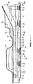
- FIG. 3 is a cross-sectional view taken along the longitudinal direction of a part of the vehicle shown in FIG.
- FIG. 4 is a perspective view of the front half of the under cover.
- FIG. 5 is a sectional view schematically showing a part of the under cover shown in FIG.
- FIG. 6 is an enlarged perspective view showing a part of the conductive yarn.
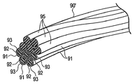
- FIG. 7 is an enlarged perspective view showing the conductive yarn used for the under cover according to the second embodiment of the present invention.
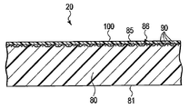
- FIG. 8 is a partial cross-sectional view of the under cover according to the third embodiment of the present invention.
- FIG. 1 shows a vehicle 10 equipped with an electric motor for traveling.
- the vehicle 10 includes a traveling electric motor 12 and a charging device 13 disposed at the rear portion of the vehicle body 11, a battery unit 14 disposed at a lower portion of the vehicle 10, an under cover 20 described later, and the like.
- An example of the vehicle 10 is an electric vehicle, but may be a hybrid vehicle including an electric motor and an internal combustion engine.
- the battery unit 14 is mounted under the floor of the vehicle body 11.
- FIG. 2 shows the frame structure 30 that forms the skeleton of the lower part of the vehicle body 11, the battery unit 14 attached to the frame structure 30, the under cover 20, and the like.
- An arrow X in FIG. 2 indicates the longitudinal direction of the vehicle body 11, and an arrow Y indicates the width direction of the vehicle body 11.
- FIG. 3 shows a cross section along a longitudinal direction of a part of the vehicle 10.
- the frame structure 30 includes a pair of left and right side members 31, 32 extending in the front-rear direction of the vehicle body 11, and cross members 33, 34, 35, 36, 37 extending in the width direction of the vehicle body 11.
- the cross members 33 to 37 are fixed to predetermined positions of the side members 31 and 32 by welding.
- the side members 31 and 32 and the cross members 33 to 37 are all made of metal (for example, steel), and also serve as an electromagnetic shield part for blocking electromagnetic waves from the periphery of the battery unit 14.
- the battery unit 14 includes a battery case 40, a battery module 41 accommodated in the battery case 40, and an electronic circuit unit 42 (respectively indicated by broken lines in FIG. 3).
- An example of the battery module 41 is obtained by connecting a plurality of cells made of lithium ion batteries in series.
- the electronic circuit unit 42 includes an electronic component that controls a monitor or a control for detecting the state of the battery module 41, and is electrically connected to the battery module 41.
- the battery case 40 includes a tray member 44 positioned on the lower side and a cover member 45 stacked on the upper side of the tray member 44, and has a box-shaped waterproof structure.
- the tray member 44 and the cover member 45 are made of an integrally molded product of resin reinforced by, for example, fibers.
- An insert member (not shown) is embedded in the resin constituting the tray member 44. This insert member is made of metal and can also function as an electromagnetic shield member.
- a floor panel 50 constituting the floor portion of the vehicle body 11 is provided.
- the floor panel 50 is made of a metal having an electromagnetic shielding effect such as steel.
- the battery unit 14 is disposed on the lower surface side of the floor panel 50. For this reason, the upper side of the electronic circuit part 42 of the battery unit 14 is magnetically shielded by the floor panel 50.
- the floor panel 50 also functions as a shield that prevents electromagnetic waves generated from the battery unit 14 from moving upward.
- a plurality of (for example, four) girder members 51, 52, 53, and 54 are provided on the lower surface side of the battery case 40.
- the beam members 51, 52, 53, 54 extend in the width direction of the vehicle body 11.
- a pair of front support members 55 are provided at the front end of the battery unit 14.
- the girder members 51, 52, 53, 54 are made of a metal material (for example, a steel plate) that has sufficient strength to support the load of the battery unit 14 and has an effect of shielding electromagnetic waves.
- the girder members 51, 52, 53, 54 are fixed to the side members 31, 32 of the vehicle body 11 by bolts 57.
- the front support member 55 is fixed to the cross member 34 with bolts 57.
- the battery unit 14 is supported by the frame structure 30 from the lower side of the vehicle body 11 via the girder members 51, 52, 53, 54 and the front support member 55. Since the girder members 51, 52, 53, 54 are disposed below the battery case 40, they can also function as a lower electromagnetic shield part of the battery unit 14.
- the battery case 40 has a front surface 40a facing the front side of the vehicle body, a rear surface 40b facing the rear side of the vehicle body, both side surfaces 40c and 40d, and a bottom surface 40e when fixed to the frame structure 30.
- An under cover 20 is disposed below the vehicle body 11, that is, below the battery unit 14.
- An example of the under cover 20 is divided into two parts, a front half 20a disposed on the front side of the vehicle body 11 and a rear half 20b disposed on the rear side of the vehicle body 11.
- One under cover 20 is configured by connecting the front half 20a and the rear half 20b.
- the total length of the under cover 20 is larger than the total length of the battery unit 14. That is, the under cover 20 has a length sufficient to cover the rear surface 40b from the front surface 40a of the battery case 40.
- the width of the under cover 20 is larger than the width of the battery case 40.
- FIG. 4 shows an example of the front half 20a of the undercover 20.
- a connecting portion 20c is formed at the rear end of the front half 20a of the undercover 20 for connection to the rear half 20b. Note that it may be a single undercover in which the front half 20a and the rear half 20b are integrated.
- the under cover 20 includes a plate portion 60 that faces the bottom surface 40e of the battery case 40, and a convex edge 61 that is formed on the periphery of the plate portion 60.
- the plate portion 60 and the convex edge 61 are integrally formed of a resin such as polypropylene (PP), for example.
- PP polypropylene
- FRP fiber reinforced resin
- the plate portion 60 has an area sufficient to cover the bottom surface 40 e of the battery case 40 when viewed from the lower side of the vehicle body 11.
- the upper surface of the plate portion 60 faces the lower surfaces of the beam members 51, 52, 53, 54.
- the convex edge 61 protrudes upward at the peripheral edge of the plate portion 60. More specifically, the convex edge 61 of the under cover 20 has a front edge portion 61a, a rear edge portion 61b, and both side edge portions 61c and 61d.
- the front edge portion 61 a is located on the front side of the vehicle body with respect to the front surface 40 a of the battery case 40.
- the rear edge portion 61b is located on the rear side of the vehicle body with respect to the rear surface 40b of the battery case 40.
- the side edge portions 61c and 61d are located on the outer side of the vehicle body with respect to both side surfaces 40c and 40d of the battery case 40, respectively.
- a plurality of bolt insertion holes 70 are formed in the under cover 20. These bolt insertion holes 70 penetrate the plate portion 60 in the thickness direction (vertical direction). Bolts 71 are respectively passed through the bolt insertion holes 70, and the bolts 71 are screwed into nut portions provided in the frame structure 30, whereby the under cover 20 is fixed to the vehicle body 11 from the lower side of the vehicle body 11.
- the under cover 20 is disposed between the pair of left and right side members 31 and 32.
- the front end of the under cover 20 is fixed to the front cross member 33 with bolts 71.
- the center part of the under cover 20 is fixed to the beam members 51, 52, 53, 54.
- the rear end of the under cover 20 is fixed to a rear cross member 37 (shown in FIG. 2) via a bracket.
- FIG. 5 is a cross-sectional view schematically showing an enlarged part of the under cover 20.
- the under cover 20 includes a resin under cover main body 81 and a cloth-shaped electromagnetic shield member 86.
- the undercover body 81 is formed by molding a resin 80 such as polypropylene into a predetermined shape.
- the conductive woven fabric 85 is disposed, for example, on the upper surface side of the undercover body 81.
- FIG. 4 shows a part of a cloth-like electromagnetic shield member 86 made of a conductive woven cloth 85.
- the under cover main body 81 faces the bottom surface 40e of the battery unit 14.
- the cloth-like electromagnetic shield member 86 prevents, for example, electromagnetic waves generated from the electric motor 12 or the like from reaching the electronic circuit unit 42 (shown in FIG. 3) in the battery case 40 from the lower side of the vehicle body 11. That is, the under cover 20 provided with the cloth-like electromagnetic shield member 86 also functions as a lower electromagnetic shield part for blocking electromagnetic waves from below the battery unit 14.
- FIG. 6 shows a part of the conductive yarn 90 constituting the conductive woven fabric 85.
- the conductive yarn 90 is composed of a plurality of conductive fibers 91.
- the conductive fiber 91 is a composite fiber composed of a fiber base 92 and a conductive layer 93 covering the fiber base 92.
- the fiber base 92 is made of, for example, polyethylene terephthalate (PET).
- PET polyethylene terephthalate
- the conductive layer 93 is made of a metal such as copper.
- the conductive layer 93 is formed on the outer peripheral surface of the fiber base 92 by a coating means such as electroless plating.
- the cloth-like electromagnetic shield member 86 of the present embodiment is constituted by the conductive woven fabric 85 in which the conductive fibers 91 are woven.
- a protective layer is provided outside the conductive layer 93 as a rust prevention measure for the conductive fibers 91.
- This protective layer is made of a rust-proof metal such as
- the fineness of the conductive fiber 91 is not particularly limited.
- the conductive fiber 91 is desirably flexible enough to follow the inner surface of the mold when the undercover 20 is molded with the mold. For this reason, for example, a material having a small fineness of 200 denier (about 22 tex) or less is employed.
- the volume resistivity of the conductive fiber 91 is suitably 10 7 ⁇ ⁇ cm or less, and preferably 10 2 ⁇ ⁇ cm or less.
- the under cover 20 is molded by a molding method using a mold such as hot pressing or stamping molding.
- the conductive woven fabric 85 has flexibility and is flexible. Therefore, the conductive woven fabric 85 can be adsorbed along the inner surface of the mold by a vacuum suction means for generating a negative pressure. That is, the conductive woven fabric 85 is disposed on the plate portion 60 of the undercover main body 81 and is preferably disposed on the peripheral convex edge 61. That is, the edge part of the conductive woven fabric 85 is arrange
- the conductive woven fabric 85 of the present embodiment is disposed across the plate portion 60 and the convex edge 61 of the undercover main body 81. For this reason, the undercover 20 provided with the conductive woven fabric 85 of the present embodiment has an electromagnetic shielding effect in the front-rear and left-right directions of the battery unit 14 as compared with a conventional undercover that does not have an electromagnetic shielding member on the convex edge 61. Is expensive.
- the resin 80 of the undercover body 81 and the conductive woven fabric 85 there is a boundary surface where both are in contact. At this boundary surface, the resin 80 and the conductive woven fabric 85 are fixed to each other by the adhesiveness of the resin 80 melted when the under cover 20 is molded. In addition, the anchor effect is obtained by the resin 80 entering between the conductive yarns 90 of the conductive woven fabric 85 and being cured. Due to this anchor effect, the fixing strength of the conductive woven fabric 85 with respect to the undercover body 81 could be increased.
- the resin 80 of the undercover body 81 is reinforced like FRP (fiber reinforced resin) by the conductive woven fabric 85 in which the resin 80 of the undercover body 81 is thus fused. For this reason, it can suppress that breakage, such as a crack of the undercover 20 by contact with the spring stone and the obstacle during traveling, can be suppressed, and the strength of the undercover 20 can be increased.
- FRP fiber reinforced resin
- the under cover 20 of this embodiment is fixed to the metal frame structure 30 with bolts 71.
- These bolts 71 respectively penetrate the under cover body 81 and the conductive woven fabric 85 in the thickness direction (vertical direction). That is, the under cover 20 is fixed to the frame structure 30 on the vehicle body 11 side by the bolts 71 inserted from the lower side of the vehicle body 11. In this case, the metal bolt 71 inserted into the bolt insertion hole 70 of the under cover 20 passes through the conductive woven fabric 85. As a result, the bolt 71 is fixed to the frame structure 30 with at least one bolt 71 in contact with the conductive woven fabric 85.
- the bolt 71 fixes the under cover 20 to a metal frame member (for example, the side members 31 and 32 and the cross member) while being in contact with the conductive woven fabric 85.
- a metal frame member for example, the side members 31 and 32 and the cross member
- the cloth-like electromagnetic shield member 86 made of the conductive woven fabric 85 is grounded to the metal vehicle body 11. Therefore, the electromagnetic shielding effect by the conductive woven fabric 85 can be enhanced.
- the under cover 20 also has an effect of rectifying the air flow generated on the lower surface side of the vehicle body 11 during traveling, and can reduce the air resistance during traveling.
- the under cover 20 also functions as a lower electromagnetic shield for blocking electromagnetic waves from below the battery unit 14.
- metal girder members 51, 52, 53, and 54 that function as lower electromagnetic shield portions are disposed below the battery unit 14.
- a further electromagnetic shielding effect is obtained by the under cover 20 provided with the girder members 51, 52, 53, 54 and the cloth-like electromagnetic shielding member 86.
- electronic components that generate electromagnetic waves are disposed between the floor panel 50 and the under cover 20. In that case, it is also possible to avoid the electromagnetic wave generated by the electronic component from affecting the electronic device above the floor panel 50.
- the electronic device is, for example, a radio, an electronic watch, a navigation system, or the like.
- the electromagnetic waves generated by such electronic components can be shielded by the floor-like panel 50 and the cloth-like electromagnetic shield member 86 of the under cover 20.
- the cloth-like electromagnetic shield member 86 provided on the under cover 20 is provided only on a part of the under cover 20 according to the strength of the electromagnetic wave reaching the battery unit 14 from the lower side of the vehicle body 11 and the region covered by the electromagnetic wave. Also good.
- the electromagnetic shielding means including the under cover 20 described above can prevent electromagnetic waves generated outside the battery case 40 from affecting the electronic circuit section 42 in the battery case 40. Further, it is possible to prevent electromagnetic waves generated in the battery case 40 from being transmitted to the outside through the under cover 20. For this reason, it is not necessary to arrange an electromagnetic shielding member such as a wire mesh in the battery case 40, and the electromagnetic shielding member does not cause a short circuit and is safe.
- the under cover 20 in which the under cover main body 81 and the conductive woven fabric 85 are integrated is disposed at the lower part of the vehicle body 11.
- the conductive cover 85 integrated with the resin 80 can suppress the undercover 20 from being shaken or vibrated by the traveling wind to some extent.
- the conductive woven fabric 85 also has an effect of suppressing cracking of the undercover 20 to some extent.
- a wire mesh was placed on the under cover as an electromagnetic shielding member.
- the metal mesh causes damage to the inner surface of the mold during undercover molding.
- due to the rigidity of the wire mesh and the instability of the shape due to the spring back it has been difficult to integrally form the resin of the undercover body.
- a clip or a screw member is required to fix the wire mesh. For this reason, it is necessary to make a hole for inserting a clip in a part of the wire mesh, and there is a possibility that the electromagnetic shielding effect cannot be obtained at the place where the hole is made.
- the conductive woven fabric 85 and the resin 80 are integrally formed at the time of heat forming the under cover 20 using a mold. For this reason, the process which fixes the electroconductive woven fabric 85 to the undercover main body 81 with a clip or a screw member after shaping
- molding is unnecessary.
- the under cover 20 in which the resin 80 and the conductive woven fabric 85 are integrally formed does not require a hole for inserting a clip for fixing the electromagnetic shield member. For this reason, the part which does not have an electromagnetic shielding effect can be decreased as much as possible.
- FIG. 7 shows a conductive yarn 90 'constituting the conductive woven fabric of the under cover according to the second embodiment.
- the under cover of the second embodiment has the same configuration as the under cover 20 of the first embodiment except for the conductive yarn 90 '.
- the conductive yarn 90 ′ is composed of conductive fibers 91 and nonconductive fibers 95.
- the conductive fiber 91 includes a fiber base 92 and a conductive layer 93 that covers the fiber base 92.
- the fiber base 92 is made of a resin such as PET.
- the conductive layer 93 is made of metal or the like.
- the non-conductive fiber 95 is made only of a resin such as PET and has no conductivity. However, the non-conductive fiber 95 has compatibility with the resin 80 of the undercover main body 81. Compatibility means that, for example, two or more different materials such as polyethylene terephthalate (PET) and polypropylene (PP) have affinity for each other, and are mixed and integrated with each other in a laminated and molten state. It is a property that can be.
- the volume specific resistance of the conductive fiber 91 is, for example, 10 7 ⁇ ⁇ cm or less.
- the volume resistivity of the nonconductive fiber 95 is, for example, 10 14 to 10 16 ⁇ ⁇ cm.
- the non-conductive fiber 95 and the resin 80 of the undercover body 81 of the second embodiment are made of resins that are compatible with each other. For this reason, the conductive woven fabric 85 in which the conductive fibers 91 and the nonconductive fibers 95 are woven underlines the conductive woven fabric 85 due to the compatibility between the nonconductive fibers 95 and the resin 80 of the undercover body 81.
- the cover body 81 can be more firmly fixed.
- the conductive woven fabric 85 constituting the cloth-shaped electromagnetic shield member 86 a woven fabric or a non-woven fabric made of a composite material of a fiber, copper, nickel, or the like electrolessly plated and a metal fiber is used. May be. In short, any cloth that is flexible and conductive enough to follow the inner surface of the mold may be used.
- Such a conductive woven fabric is pressed in the thickness direction in a heated state with the resin 80 of the undercover main body 81 by hot pressing using a mold or stamping molding. Thereby, the under cover 20 formed by integrally molding the resin 80 and the conductive woven fabric 85 is obtained.
- FIG. 8 shows a part of the under cover 20 according to the third embodiment.
- the conductive woven fabric 85 constituting the under cover 20 is covered with the laminate resin layer 100 on the surface opposite to the under cover body 81 (the upper surface of the conductive woven fabric 85).
- the laminate resin layer 100 and the resin 80 of the undercover body 81 are made of resins that are compatible with each other.
- the resin 80 of the undercover body 81 oozes out from the conductive woven fabric 85 toward the laminate resin layer 100 and is integrated with the laminate resin layer 100.
- the undercover body 81 and the conductive woven fabric 85 can be more firmly fixed.
- the upper surface (outer surface side) of the conductive woven fabric 85 is covered with the laminate resin layer 100.
- the undercover body 81 is waterproof. For this reason, even if the conductive layer 93 of the conductive fiber 91 constituting the conductive woven fabric 85 is made of only copper and is not covered with the rust-proof metal, the conductive fiber 91 can be prevented from being rusted.
- a vehicle that travels only by an electric motor
- the present invention can also be applied to a hybrid vehicle including an electric motor and an engine (internal combustion engine).
- an engine internal combustion engine
Landscapes
- Engineering & Computer Science (AREA)
- Mechanical Engineering (AREA)
- Chemical & Material Sciences (AREA)
- Combustion & Propulsion (AREA)
- Transportation (AREA)
- Acoustics & Sound (AREA)
- Physics & Mathematics (AREA)
- Chemical Kinetics & Catalysis (AREA)
- Electrochemistry (AREA)
- General Chemical & Material Sciences (AREA)
- Body Structure For Vehicles (AREA)
- Arrangement Or Mounting Of Propulsion Units For Vehicles (AREA)
- Battery Mounting, Suspending (AREA)
- Shielding Devices Or Components To Electric Or Magnetic Fields (AREA)
Abstract
走行用電動モータとバッテリユニットを有する車両において電磁シールド効果を発揮できるアンダーカバーを提供する。 車体の下部にバッテリユニットが配置されている。バッテリユニットの下方にアンダーカバー(20)が配置されている。アンダーカバー(20)は、車両走行中の跳ね石や障害物がバッテリケースに直接触れることを防ぎ、かつ、走行中に生じる車体下部の空気の流れを整流する機能などを有している。アンダーカバー(20)はアンダーカバー本体(81)と導電性織布(85)からなる布状電磁シールド部材(86)とを備えている。導電性織布(85)は柔軟でしなやかであり、アンダーカバー本体(81)の樹脂(80)を加熱した状態で一体成形される。樹脂(80)が導電性織布(85)に融着することによって得られるアンカー効果によって、導電性織布(85)がアンダーカバー本体(81)の樹脂(80)に固定されている。
Description
本発明は、走行用の電動モータとバッテリユニットとを備えた車両に設ける車両用のアンダーカバーに関する。
バッテリを電源とする電動モータを備えた車両は、例えば電動モータやバッテリあるいは電流制御回路などから電磁波が生じることが知られている。車両に発生する電磁波は、車体に装備される各種の電気部品に影響を与える懸念がある。このため、電磁波の影響を受けるおそれのある電気部品、あるいは電磁波発生源となる電装品に関して、電磁シールド対策を講じることが望まれる。
例えばバッテリケースの電磁シールド対策として、下記の特許文献1に記載されているように、電磁波を反射する効果のある電磁シールド塗料をバッテリケースの表面に塗布することが提案されている。あるいは特許文献2に記載されているように、バッテリケースの電磁シールド対策として樹脂層に金網を埋設することも提案されている。
特許文献1のように、バッテリケースの表面等に電磁シールド塗料を塗布する場合、電磁シールド塗料自体が高価である。しかも、塗料を塗布する工程や塗料を乾燥させる工程なども必要であり、電磁シールド対策のために時間がかかるだけでなく、経費が著しく高くつく。
特許文献2のようにバッテリケースに金網を埋設した場合には、バッテリケースの外部に配置された電子部品に対してバッテリケースの外部から作用する電磁波をシールドすることができない。またバッテリケースは、内部に収容するバッテリモジュールの仕様に応じて形状が変化することがある。このため各種バッテリケースに応じた電磁シールド対策を講じなければならず、汎用性に欠けるという問題がある。またバッテリケース内に金網を設けることは、高電圧の雰囲気にあるバッテリケースの内部の狭い空間に電気的な短絡(ショート)の要因をつくることになる。
従って本発明の目的は、電磁波シールド手段としても有効に機能することができるアンダーカバーを提供することにある。
本発明は、車両下部に搭載されるバッテリユニットの下方に配置されるアンダーカバーであって、前記バッテリユニットの底面と対向する樹脂製のアンダーカバー本体に、導電性繊維が織り込まれた導電性織布を重ねて配置し、前記アンダーカバー本体と前記導電性織布とが融着されている。
本発明の1つの実施形態では、前記アンダーカバー本体はその周縁に上方に突出する凸縁を有し、前記導電性織布が前記凸縁に囲まれた領域にわたって配置されている。この実施形態において、前記凸縁は、前記バッテリユニットの前面よりも車体前側に位置する前縁部と、前記バッテリユニットの後面よりも車体後側に位置する後縁部と、前記バッテリユニットの両側面よりも車体外側に位置する両側縁部とを有し、これら前縁部と、後縁部と、両側縁部とにわたって、前記導電性織布の縁部が配置されていてもよい。
また本発明の1つの実施形態では、前記アンダーカバー本体と前記導電性織布とを厚さ方向に貫通する金属製のボルトを有し、前記ボルトは、前記導電性織布に接触した状態で前記アンダーカバーを車体の金属製フレーム部材に固定する。この構成によれば、前記導電性織布がボルトを介して車体側にアースされた状態となる。
また前記導電性織布の上面に、ラミネート樹脂層が積層されてもよい。この実施形態において、前記ラミネート樹脂層と前記アンダーカバー本体の樹脂とが互いに相溶性(compatibility)を有する樹脂(例えばポリプロピレン)からなり、前記ラミネート樹脂層と前記アンダーカバー本体の樹脂とが、前記導電性織布を間に挟んだ状態で互いに融着していてもよい。
本発明によれば、車体下部に配置されるアンダーカバーを利用してバッテリユニット等に対する電磁シールド対策を講じることができる。また、バッテリユニットから発生する電磁波が周囲の電気部品等に影響を及ぼすこともアンダーカバーを利用して防止できる。
以下に本発明の第1の実施形態について、図1から図6を参照して説明する。
図1は走行用の電動モータを備えた車両10を示している。この車両10は、車体11の後部に配置された走行用の電動モータ12および充電装置13と、車両10の下部に配置されたバッテリユニット14と、後述するアンダーカバー20などを備えている。車両10の一例は電気自動車であるが、電動モータと内燃機関を備えたハイブリッド車であってもよい。バッテリユニット14は車体11の床下に搭載されている。
図1は走行用の電動モータを備えた車両10を示している。この車両10は、車体11の後部に配置された走行用の電動モータ12および充電装置13と、車両10の下部に配置されたバッテリユニット14と、後述するアンダーカバー20などを備えている。車両10の一例は電気自動車であるが、電動モータと内燃機関を備えたハイブリッド車であってもよい。バッテリユニット14は車体11の床下に搭載されている。
図2は、車体11の下部の骨格をなすフレーム構体30と、フレーム構体30に取付けられたバッテリユニット14と、アンダーカバー20などを示している。図2中の矢印Xが車体11の前後方向、矢印Yが車体11の幅方向を示している。図3は、車両10の一部の車体前後方向に沿う断面を示している。
フレーム構体30は、車体11の前後方向に延びる左右一対のサイドメンバ31,32と、車体11の幅方向に延びるクロスメンバ33,34,35,36,37とを含んでいる。クロスメンバ33~37は、サイドメンバ31,32の所定位置に溶接によって固定されている。サイドメンバ31,32とクロスメンバ33~37は、いずれも金属(例えば鋼)からなり、バッテリユニット14の周囲からの電磁波を遮断するための電磁シールド部としての機能も兼ねている。
バッテリユニット14は、バッテリケース40と、バッテリケース40内に収納されたバッテリモジュール41および電子回路部42(それぞれ図3中に破線で示す)を含んでいる。バッテリモジュール41の一例は、リチウムイオン電池からなる複数個のセルを直列に接続したものである。電子回路部42は、バッテリモジュール41の状態を検出するモニタや制御等をつかさどる電子部品などを含み、バッテリモジュール41に電気的に接続されている。
バッテリケース40は、下側に位置するトレイ部材44と、トレイ部材44の上側に重ねたカバー部材45とを備え、箱形の防水構造をなしている。トレイ部材44とカバー部材45は、例えば繊維によって強化された樹脂の一体成形品からなる。トレイ部材44を構成する樹脂の内部にインサート部材(図示せず)が埋設されている。このインサート部材は金属からなり、電磁シールド部材としても機能することができる。
図3に示すように、車体11の床部を構成するフロアパネル50が設けられている。フロアパネル50は鋼等の電磁シールド効果のある金属からなる。このフロアパネル50の下面側に前記バッテリユニット14が配置されている。このためバッテリユニット14の電子回路部42の上側がフロアパネル50によって磁気シールドされる。このフロアパネル50は、バッテリユニット14から発生する電磁波が上方に向かうことを阻止するシールドとしても機能する。
図2と図3に示されるように、バッテリケース40の下面側に複数本(例えば4本)の桁部材51,52,53,54が設けられている。桁部材51,52,53,54は、それぞれ車体11の幅方向に延びている。バッテリユニット14の前端部に一対の前側支持部材55が設けられている。
桁部材51,52,53,54は、バッテリユニット14の荷重を支えるに足る強度を有し、かつ、電磁波をシールドする効果のある金属材料(例えば鋼板)によって構成されている。桁部材51,52,53,54は、車体11のサイドメンバ31,32にボルト57によって固定される。前側支持部材55は、クロスメンバ34にボルト57によって固定される。
このようにバッテリユニット14は、車体11の下側から桁部材51,52,53,54と前側支持部材55とを介して、フレーム構体30に支持される。桁部材51,52,53,54はバッテリケース40の下側に配置されているため、バッテリユニット14の下側電磁シールド部としても機能することができる。バッテリケース40は、フレーム構体30に固定された状態において車体前側を向く前面40aと、車体後側を向く後面40bと、両側面40c,40dと、底面40eとを有している。
車体11の下部すなわちバッテリユニット14の下方にアンダーカバー20が配置されている。アンダーカバー20の一例は、車体11の前側に配置される前半部20aと、車体11の後側に配置される後半部20bとに二分割されている。前半部20aと後半部20bとを接続することにより、1つのアンダーカバー20が構成されている。このアンダーカバー20の全長はバッテリユニット14の全長よりも大きい。すなわちこのアンダーカバー20は、バッテリケース40の前面40aから後面40bを覆うに足る長さを有している。またアンダーカバー20の幅は、バッテリケース40の幅よりも大きい。
図4は、アンダーカバー20の前半部20aの一例を示している。アンダーカバー20の前半部20aの後端には、後半部20bとの接続をなすための接続部20cが形成されている。なお、前半部20aと後半部20bとが一体化している1枚物のアンダーカバーであってもよい。
このアンダーカバー20は、バッテリケース40の底面40eに対向するプレート部60と、プレート部60の周縁に形成された凸縁61とを有している。プレート部60と凸縁61とは、例えばポリプロピレン(PP)等の樹脂により一体成形されている。なお、アンダーカバー20の材料に繊維強化樹脂(FRP)が使用されてもよい。プレート部60は、車体11の下側から見て、バッテリケース40の底面40eを覆うに足る面積を有している。プレート部60の上面は、桁部材51,52,53,54の下面と対向している。
凸縁61は、プレート部60の周縁において上方に突出している。さらに詳しくは、アンダーカバー20の凸縁61は、前縁部61aと、後縁部61bと、両側縁部61c,61dとを有している。前縁部61aは、バッテリケース40の前面40aよりも車体前側に位置している。後縁部61bは、バッテリケース40の後面40bよりも車体後側に位置している。側縁部61c,61dは、それぞれ、バッテリケース40の両側面40c,40dよりも車体外側に位置している。
このアンダーカバー20に、複数のボルト挿入孔70(図4に一部を示す)が形成されている。これらボルト挿入孔70は、プレート部60を厚さ方向(上下方向)に貫通している。ボルト挿入孔70にそれぞれボルト71を通し、このボルト71をフレーム構体30に設けられたナット部にねじ込むことにより、アンダーカバー20が車体11の下側から車体11に固定される。
図2に示されるように、アンダーカバー20は左右一対のサイドメンバ31,32間にわたって配置されている。アンダーカバー20の前端は、前側のクロスメンバ33にボルト71によって固定されている。アンダーカバー20の中央部は、桁部材51,52,53,54に固定されている。アンダーカバー20の後端は、後側のクロスメンバ37(図2に示す)にブラケットを介して固定されている。
図5は、アンダーカバー20の一部を拡大して模式的に示す断面図である。このアンダーカバー20は、樹脂製のアンダーカバー本体81と、布状電磁シールド部材86とを備えている。アンダーカバー本体81は、例えばポリプロピレン等の樹脂80を所定形状に成形したものである。導電性織布85は、アンダーカバー本体81の例えば上面側に配置されている。図4に導電性織布85からなる布状電磁シールド部材86の一部が示されている。アンダーカバー本体81はバッテリユニット14の底面40eと対向している。
布状電磁シールド部材86は、例えば電動モータ12などから発生する電磁波が、車体11の下側から、バッテリケース40内の電子回路部42(図3に示す)に及ぶことを防ぐ。すなわち布状電磁シールド部材86を備えたアンダーカバー20は、バッテリユニット14の下方からの電磁波を遮断するための下側電磁シールド部としての機能を兼ねている。
図6は、導電性織布85を構成する導電糸90の一部を示している。導電糸90は、複数の導電性繊維91からなる。導電性繊維91は、繊維基材92と繊維基材92を覆う導電層93とからなる複合繊維である。繊維基材92は、例えばポリエチレンテレフタレート(PET)からなる。導電層93は、銅などの金属からなる。導電層93は、無電解めっきなどのコーティング手段よって、繊維基材92の外周面に形成されている。このように本実施形態の布状電磁シールド部材86は、導電性繊維91が織り込まれた導電性織布85によって構成されている。さらにこの実施形態の場合、導電性繊維91の防錆対策として、導電層93の外側に保護層が設けられている。この保護層は、ニッケルなどの防錆金属からなる。
導電性繊維91の繊度は、特に限定されるものではない。導電性繊維91は、アンダーカバー20を金型によって成形する際に、金型内面に追従できるように十分しなやかなものが望ましい。このため、例えば200デニール(約22tex)以下の繊度の小さなものが採用される。導電性繊維91の体積固有抵抗は、一般に107Ω・cm以下が適しており、好ましくは102Ω・cm以下である。
このアンダーカバー20は、例えばホットプレスやスタンピング成形などのように金型を用いる成形方法によって成形される。導電性織布85は柔軟性を有し、しなやかである。このため導電性織布85は、負圧を発生させるバキューム吸引手段などによって、金型内面に沿わせて吸着させることができる。すなわちこの導電性織布85は、アンダーカバー本体81のプレート部60に配置され、かつ、好ましくは周囲の凸縁61にも配置されている。つまり導電性織布85の縁部が、プレート部60の前縁部61aと、後縁部61bと、両側縁部61c,61dに配置されている。このように導電性織布85が凸縁61に囲まれた領域にわたって配置されていてもよい。
本実施形態の導電性織布85は、アンダーカバー本体81のプレート部60と凸縁61とにわたって配置されている。このため本実施形態の導電性織布85を備えたアンダーカバー20は、凸縁61に電磁シールド部材を有しない従来のアンダーカバーと比較して、バッテリユニット14の前後および左右方向に対する電磁シールド効果が高い。
アンダーカバー本体81の樹脂80と導電性織布85との間に、両者が接する境界面が存在する。この境界面においては、アンダーカバー20の成形時に溶融した樹脂80の接着性によって、樹脂80と導電性織布85とが互いに固定されている。しかも、樹脂80が導電性織布85の導電糸90間に入り込んで硬化することによって、アンカー効果が得られている。このアンカー効果により、アンダーカバー本体81に対する導電性織布85の固定強度を高めることができた。
このようにアンダーカバー本体81の樹脂80が融着した導電性織布85によって、アンダーカバー本体81の樹脂80がFRP(繊維強化樹脂)のように強化されている。このため、走行中の跳ね石や障害物との接触によるアンダーカバー20の割れ等の破損が進展することを抑制することができ、アンダーカバー20の強度を高めることができる。
本実施形態のアンダーカバー20は、ボルト71によって金属製のフレーム構体30に固定されている。これらボルト71は、それぞれアンダーカバー本体81と導電性織布85とを厚さ方向(上下方向)に貫通している。すなわちこのアンダーカバー20は、車体11の下側から挿入されるボルト71によって、車体11側のフレーム構体30に固定される。この場合、アンダーカバー20のボルト挿入孔70に挿入された金属製のボルト71が、導電性織布85を貫通する。このことにより、少なくとも1つのボルト71が導電性織布85に接触した状態のもとで、ボルト71がフレーム構体30に固定される。
すなわちこのボルト71は、導電性織布85に接触した状態で、アンダーカバー20を金属製フレーム部材(例えばサイドメンバ31,32やクロスメンバ等)に固定する。このため導電性織布85からなる布状電磁シールド部材86が金属製の車体11にアースされる。よって、導電性織布85による電磁シールド効果を高めることができる。
このアンダーカバー20は、走行中に車体11の下面側に生じる空気流を整流する効果もあり、走行中の空気抵抗を減少させることができる。アンダーカバー20は、バッテリユニット14の下方からの電磁波を遮断するための下側電磁シールド部としての機能を兼ねている。しかもバッテリユニット14の下方には、下側電磁シールド部として機能する金属製の桁部材51,52,53,54が配置されている。これら桁部材51,52,53,54と布状電磁シールド部材86を備えたアンダーカバー20とによって、さらなる電磁シールド効果が得られている。
車両によっては、フロアパネル50とアンダーカバー20との間に、電磁波を生じる電子部品が配置されている。その場合には、電子部品が発生する電磁波がフロアパネル50の上方にある電子機器に影響を及ぼすことも回避できる。電子機器は、例えばラジオや電子時計、ナビゲーションシステム等である。このような電子部品が発生する電磁波は、フロアパネル50と前記アンダーカバー20の布状電磁シールド部材86によって、遮蔽することができる。
なお、アンダーカバー20に設ける布状電磁シールド部材86は、車体11の下側からバッテリユニット14に到達する電磁波の強さや、電磁波が及ぶ領域に応じて、アンダーカバー20の一部のみに設けてもよい。
以上説明したアンダーカバー20を含む電磁シールド手段により、バッテリケース40の外部で発生した電磁波がバッテリケース40内の電子回路部42に影響を与えることを防止できる。また、バッテリケース40内で発生した電磁波がアンダーカバー20を透過して外部に放出されることを防止できる。このためバッテリケース40に金網等の電磁シールド部材を配置せずにすみ、電磁シールド部材がショートの原因とならず安全である。
以上説明したように本実施形態によれば、バッテリユニット14よりも広い面積を有するアンダーカバー20が導電性織布からなる電磁シールド部材を一体に有している。このため、バッテリユニット14の形状や配置が変更になっても共通のアンダーカバー20を用いることが可能である。また、バッテリユニット14の外部に配置される電子部品に対しても、アンダーカバー20によって電磁シールドすることができる。
このようにアンダーカバー本体81と導電性織布85とが一体化しているアンダーカバー20が車体11の下部に配置されている。このことにより、アンダーカバー20が走行風によって揺れたり、振動したりすることを、樹脂80と一体化した導電性織布85によってある程度抑制することができる。導電性織布85はアンダーカバー20のひび割れをある程度抑制する効果もある。
なお、電磁シールド部材として金網をアンダーカバーの上に置くことも考えられた。しかし金網は、アンダーカバー成形時の金型の内面を傷付ける原因となる。しかも金網の剛性とスプリングバックによる形状不安定により、アンダーカバー本体の樹脂と一体成形することが困難であった。しかも金網をアンダーカバー上に置く場合には、金網を固定するのにクリップやねじ部材が必要となる。このため金網の一部にクリップ挿入用の孔を開ける必要があり、孔を開けた箇所では電磁シールド効果が得られない可能性がある。
しかるに本実施形態では、前記したように金型によるアンダーカバー20の加熱成形時に、導電性織布85と樹脂80とを一体成形する。このため、成形後に導電性織布85をクリップやねじ部材によってアンダーカバー本体81に固定する工程が不要である。しかも樹脂80と導電性織布85とが一体成形されたアンダーカバー20は、電磁シールド部材固定用のクリップを挿入する孔が不要である。このため電磁シールド効果を有しない箇所を極力少なくすることができる。
図7は、第2の実施形態のアンダーカバーの導電性織布を構成する導電糸90´を示している。第2の実施形態のアンダーカバーは、導電糸90´以外の構成が第1の実施形態のアンダーカバー20と共通である。この導電糸90´は、導電性繊維91と非導電性繊維95とからなる。導電性繊維91は、前記第1の実施形態と同様に、繊維基材92と、繊維基材92を被覆する導電層93とを有している。繊維基材92はPET等の樹脂からなる。導電層93は金属等からなる。
非導電性繊維95はPET等の樹脂のみからなり、導電性を有していない。しかし非導電性繊維95は、アンダーカバー本体81の樹脂80に対して相溶性(compatibility)を有している。相溶性とは、例えばポリエチレンテレフタレート(PET)とポリプロピレン(PP)のように、互いに異なる2種類以上の物質が互いに親和性を有し、互いに積層され溶融した状態において互いに混じり合って一体化することができる性質である。導電性繊維91の体積固有抵抗は、例えば107Ω・cm以下である。非導電性繊維95の体積固有抵抗は、例えば1014~1016Ω・cmである。
この第2の実施形態の非導電性繊維95とアンダーカバー本体81の樹脂80とは、互いに相溶性を有する樹脂からなる。このため導電性繊維91と非導電性繊維95とが織り込まれた導電性織布85は、非導電性繊維95とアンダーカバー本体81の樹脂80との相溶性により、導電性織布85をアンダーカバー本体81に対してさらに強固に固定することができる。
なお、布状電磁シールド部材86を構成する導電性織布85の他の形態として、繊維と銅、ニッケルなどを無電解めっきした繊維と、金属繊維との複合体素材による織布あるいは不織布であってもよい。要するに、金型内面に追従できる程度にしなやかでかつ導電性を有する布帛(cloth)であればよい。このような導電性織布を、金型を用いるホットプレスやスタンピング成形によってアンダーカバー本体81の樹脂80と加熱状態で厚さ方向に加圧する。これにより、樹脂80と導電性織布85とを一体成形してなるアンダーカバー20を得るようにしている。
図8は、第3の実施形態に係るアンダーカバー20の一部を示している。このアンダーカバー20を構成する導電性織布85は、アンダーカバー本体81とは反対側の面(導電性織布85の上面)がラミネート樹脂層100によって覆われている。ラミネート樹脂層100とアンダーカバー本体81の樹脂80とは、互いに相溶性を有する樹脂からなる。金型による加熱成形時に、アンダーカバー本体81の樹脂80が導電性織布85からラミネート樹脂層100側に染み出てラミネート樹脂層100と一体化する。これにより、アンダーカバー本体81と導電性織布85とをより強固に固定することができる。また導電性織布85の上面(外面側)がラミネート樹脂層100によって覆われている。この場合、アンダーカバー本体81が防水仕様となる。このため、導電性織布85を構成する導電性繊維91の導電層93が、銅のみであって防錆金属で覆われていなくても、導電性繊維91が錆びることを回避できる。
前記実施形態では電動モータのみで走行する車両(電気自動車)について説明したが、本発明は電動モータとエンジン(内燃機関)とを備えたハイブリッド車に適用することもできる。また本発明を実施するに当たり、車体やバッテリユニットの具体的な形状、アンダーカバーおよび導電性織布の形状、配置をはじめとして、発明の構成要素の構造及び配置を適宜に変更して実施できることは言うまでもない。
10…車両、11…車体、12…電動モータ、14…バッテリユニット、20…アンダーカバー、30…フレーム構体、31,32…サイドメンバ(金属製フレーム部材)、33,34,35,36,37…クロスメンバ(金属製フレーム部材)、40…バッテリケース、51,52,53,54…桁部材、60…プレート部、61…凸縁、71…ボルト、80…樹脂、81…アンダーカバー本体、85…導電性織布、85…布状電磁シールド部材、91…導電性繊維、100…ラミネート樹脂層。
Claims (5)
- 車両下部に搭載されるバッテリユニット(14)の下方に配置されるアンダーカバー(20)であって、
前記バッテリユニット(14)の底面(40e)と対向する樹脂製のアンダーカバー本体(85)に、導電性繊維(91)が織り込まれた導電性織布(85)を重ねて配置し、前記アンダーカバー本体(85)と前記導電性織布(85)とが融着されていることを特徴とするアンダーカバー。 - 前記アンダーカバー本体(85)の周縁に上方に突出する凸縁(61)を有し、前記導電性織布(85)が前記凸縁(61)に囲まれた領域にわたって配置されたことを特徴とする請求項1に記載のアンダーカバー。
- 前記アンダーカバー本体(85)と前記導電性織布(85)とを厚さ方向に貫通する金属製のボルト(71)を有し、前記ボルト(71)は、前記導電性織布(85)に接触した状態で前記アンダーカバーを車体(11)の金属製フレーム部材に固定したことを特徴とする請求項1に記載のアンダーカバー。
- 前記アンダーカバー本体(85)と前記導電性織布(85)とを厚さ方向に貫通する金属製のボルト(71)を有し、前記ボルト(71)は、前記導電性織布(85)に接触した状態で前記アンダーカバーを車体(11)の金属製フレーム部材に固定したことを特徴とする請求項2に記載のアンダーカバー。
- 前記導電性織布(85)の上面に、ラミネート樹脂層(100)が積層されたことを特徴とする請求項1から4のいずれか1項に記載のアンダーカバー。
Priority Applications (2)
| Application Number | Priority Date | Filing Date | Title |
|---|---|---|---|
| EP13738429.3A EP2805877B1 (en) | 2012-01-17 | 2013-01-15 | Undercover |
| US14/332,822 US20140329125A1 (en) | 2012-01-17 | 2014-07-16 | Undercover |
Applications Claiming Priority (2)
| Application Number | Priority Date | Filing Date | Title |
|---|---|---|---|
| JP2012007256A JP5970825B2 (ja) | 2012-01-17 | 2012-01-17 | アンダーカバー |
| JP2012-007256 | 2012-01-17 |
Related Child Applications (1)
| Application Number | Title | Priority Date | Filing Date |
|---|---|---|---|
| US14/332,822 Continuation US20140329125A1 (en) | 2012-01-17 | 2014-07-16 | Undercover |
Publications (1)
| Publication Number | Publication Date |
|---|---|
| WO2013108747A1 true WO2013108747A1 (ja) | 2013-07-25 |
Family
ID=48799172
Family Applications (1)
| Application Number | Title | Priority Date | Filing Date |
|---|---|---|---|
| PCT/JP2013/050561 Ceased WO2013108747A1 (ja) | 2012-01-17 | 2013-01-15 | アンダーカバー |
Country Status (4)
| Country | Link |
|---|---|
| US (1) | US20140329125A1 (ja) |
| EP (1) | EP2805877B1 (ja) |
| JP (1) | JP5970825B2 (ja) |
| WO (1) | WO2013108747A1 (ja) |
Cited By (1)
| Publication number | Priority date | Publication date | Assignee | Title |
|---|---|---|---|---|
| WO2015067430A1 (de) * | 2013-11-11 | 2015-05-14 | Bayerische Motoren Werke Aktiengesellschaft | Abschirmung gegen elektromagnetische strahlung bei einem elektromotorrad |
Families Citing this family (33)
| Publication number | Priority date | Publication date | Assignee | Title |
|---|---|---|---|---|
| JP5929211B2 (ja) * | 2012-01-13 | 2016-06-01 | 三菱自動車工業株式会社 | アンダーカバー |
| JP6145422B2 (ja) * | 2014-05-13 | 2017-06-14 | 本田技研工業株式会社 | 車両の下部構造 |
| US10978763B2 (en) * | 2015-01-22 | 2021-04-13 | Ford Global Technologies, Llc | Battery pack cover for an electrified vehicle |
| DE102015208312A1 (de) | 2015-05-05 | 2016-11-10 | Volkswagen Aktiengesellschaft | Zweispuriges Fahrzeug |
| JP6101767B1 (ja) * | 2015-09-30 | 2017-03-22 | 富士重工業株式会社 | 衝突荷重緩和構造体 |
| AT518034B1 (de) * | 2015-12-02 | 2018-02-15 | Geoprospectors Gmbh | Landwirtschaftliche Arbeitsmaschine mit einem Bodensensor |
| US9758030B2 (en) | 2016-02-09 | 2017-09-12 | NextEv USA, Inc. | Replaceable battery assembly having a latching mechanism |
| US10017037B2 (en) * | 2016-02-09 | 2018-07-10 | Nio Usa, Inc. | Vehicle having a battery pack directly attached to the cross rails of a frame structure |
| JP6520808B2 (ja) * | 2016-04-21 | 2019-05-29 | トヨタ自動車株式会社 | 車両のバッテリ搭載構造 |
| US10933937B2 (en) * | 2016-06-06 | 2021-03-02 | Yanyan SHANG | Self-balancing scooter |
| JP6396960B2 (ja) * | 2016-08-31 | 2018-09-26 | 株式会社Subaru | 電池パック |
| IT201600101276A1 (it) * | 2016-10-10 | 2018-04-10 | Enrico Pronzato | Piastra di protezione per sottoscocca di autoveicolo. |
| US9884545B1 (en) * | 2016-11-01 | 2018-02-06 | Ford Global Technologies, Llc | Traction battery mounting assembly and securing method |
| US10272759B2 (en) * | 2017-01-30 | 2019-04-30 | GM Global Technology Operations LLC | Structural enhancements of an electric vehicle |
| DE102017110700B4 (de) * | 2017-05-17 | 2021-12-23 | Romeo Kopf | Aufbau einer antimagnetischen Schutzverkleidung für einen ferromagnetischen Unterbau |
| JP6992585B2 (ja) * | 2018-02-22 | 2022-01-13 | トヨタ自動車株式会社 | 車両下部構造 |
| US10259507B1 (en) * | 2018-03-22 | 2019-04-16 | Honda Motor Co., Ltd. | Skid plate and underbody assembly for use with an off-road vehicle |
| CN108528542B (zh) * | 2018-03-27 | 2019-08-23 | 吉利汽车研究院(宁波)有限公司 | 一种电池保护板及车辆 |
| KR102575355B1 (ko) * | 2018-04-26 | 2023-09-07 | 현대자동차주식회사 | 차량용 배터리 케이스 |
| US10752072B2 (en) | 2018-09-05 | 2020-08-25 | Ford Global Technologies, Llc | Electrified vehicle with vibration isolator within frame and corresponding method |
| JP7099949B2 (ja) * | 2018-12-25 | 2022-07-12 | トヨタ自動車株式会社 | 車両下部構造 |
| FR3099125B1 (fr) * | 2019-07-24 | 2022-03-18 | Psa Automobiles Sa | Carter de protection muni d’un verrou mobile |
| FR3099742B1 (fr) * | 2019-08-06 | 2022-01-14 | Psa Automobiles Sa | Déflecteur à bords longitudinaux à extensions, pour un soubassement de véhicule |
| FR3099744B1 (fr) * | 2019-08-08 | 2021-07-16 | Psa Automobiles Sa | Déflecteur à parois de calage, pour une structure d’un soubassement de véhicule |
| JP6977792B2 (ja) * | 2020-01-15 | 2021-12-08 | 株式会社デンソー | 電池モジュール |
| JP7184212B2 (ja) * | 2020-06-09 | 2022-12-06 | 日産自動車株式会社 | 駆動装置の保護構造 |
| JP7578913B2 (ja) | 2021-03-22 | 2024-11-07 | スズキ株式会社 | 車両用アンダーカバー構造 |
| JP7549805B2 (ja) | 2021-03-22 | 2024-09-12 | スズキ株式会社 | 車両用バッテリパック周辺構造 |
| JP7620878B2 (ja) * | 2021-03-22 | 2025-01-24 | スズキ株式会社 | 車両用アンダーカバー構造 |
| JP7707662B2 (ja) * | 2021-06-01 | 2025-07-15 | マツダ株式会社 | 車体構造 |
| DE102021118756B4 (de) * | 2021-07-20 | 2023-03-23 | Dr. Ing. H.C. F. Porsche Aktiengesellschaft | Hochvoltkomponente für ein Hochvoltbordnetz eines wenigstens teilweise elektrisch betriebenen Kraftfahrzeugs |
| FR3153315A1 (fr) * | 2023-09-22 | 2025-03-28 | Psa Automobiles Sa | Structure de châssis d’un véhicule électrique |
| DE102024105009B3 (de) | 2024-02-22 | 2025-02-20 | Dr. Ing. H.C. F. Porsche Aktiengesellschaft | Kraftfahrzeug mit einem Unterfahrschutz |
Citations (4)
| Publication number | Priority date | Publication date | Assignee | Title |
|---|---|---|---|---|
| JPH08186390A (ja) | 1994-12-28 | 1996-07-16 | Uchihama Kasei Kk | 電気自動車用バッテリーケース |
| JP2001294048A (ja) | 2000-04-13 | 2001-10-23 | Toyota Motor Corp | 車両用電源装置 |
| WO2009001483A1 (ja) * | 2007-06-27 | 2008-12-31 | Nagoya Oilchemical Co., Ltd. | 自動車用床裏被覆材、及び自動車用床裏被覆材の製造方法 |
| JP2011143763A (ja) * | 2010-01-12 | 2011-07-28 | Toyota Boshoku Corp | 自動車外装材 |
Family Cites Families (11)
| Publication number | Priority date | Publication date | Assignee | Title |
|---|---|---|---|---|
| JP3777981B2 (ja) * | 2000-04-13 | 2006-05-24 | トヨタ自動車株式会社 | 車両用電源装置 |
| JP2004027098A (ja) * | 2002-06-27 | 2004-01-29 | Sumitomo Chem Co Ltd | ポリプロピレン樹脂組成物 |
| JP5095072B2 (ja) * | 2004-03-22 | 2012-12-12 | 住友化学株式会社 | 樹脂成形品の製造方法 |
| JP5078418B2 (ja) * | 2007-04-20 | 2012-11-21 | 旭化成ケミカルズ株式会社 | 電池ケース |
| JP5029263B2 (ja) * | 2007-09-28 | 2012-09-19 | 三菱自動車工業株式会社 | 電気自動車 |
| JP2009164265A (ja) * | 2007-12-28 | 2009-07-23 | Nok Corp | 電磁波遮蔽筐体 |
| US8007904B2 (en) * | 2008-01-11 | 2011-08-30 | Fiber Innovation Technology, Inc. | Metal-coated fiber |
| WO2010103639A1 (ja) * | 2009-03-12 | 2010-09-16 | トヨタ自動車株式会社 | 電動車両 |
| JP5417984B2 (ja) * | 2009-05-18 | 2014-02-19 | 株式会社デンソー | 電子装置 |
| WO2012012614A2 (en) * | 2010-07-23 | 2012-01-26 | Syscom Advanced Materials | Electrically conductive metal-coated fibers, continuous process for preparation thereof, and use thereof |
| US20120100414A1 (en) * | 2010-10-22 | 2012-04-26 | Gm Global Technology Operations, Inc. | Encapsulated emi/rfi shielding for a non-conductive thermosetting plastic composite phev battery cover |
-
2012
- 2012-01-17 JP JP2012007256A patent/JP5970825B2/ja active Active
-
2013
- 2013-01-15 EP EP13738429.3A patent/EP2805877B1/en active Active
- 2013-01-15 WO PCT/JP2013/050561 patent/WO2013108747A1/ja not_active Ceased
-
2014
- 2014-07-16 US US14/332,822 patent/US20140329125A1/en not_active Abandoned
Patent Citations (4)
| Publication number | Priority date | Publication date | Assignee | Title |
|---|---|---|---|---|
| JPH08186390A (ja) | 1994-12-28 | 1996-07-16 | Uchihama Kasei Kk | 電気自動車用バッテリーケース |
| JP2001294048A (ja) | 2000-04-13 | 2001-10-23 | Toyota Motor Corp | 車両用電源装置 |
| WO2009001483A1 (ja) * | 2007-06-27 | 2008-12-31 | Nagoya Oilchemical Co., Ltd. | 自動車用床裏被覆材、及び自動車用床裏被覆材の製造方法 |
| JP2011143763A (ja) * | 2010-01-12 | 2011-07-28 | Toyota Boshoku Corp | 自動車外装材 |
Cited By (2)
| Publication number | Priority date | Publication date | Assignee | Title |
|---|---|---|---|---|
| WO2015067430A1 (de) * | 2013-11-11 | 2015-05-14 | Bayerische Motoren Werke Aktiengesellschaft | Abschirmung gegen elektromagnetische strahlung bei einem elektromotorrad |
| US10214261B2 (en) | 2013-11-11 | 2019-02-26 | Bayerische Motoren Werke Aktiengesellschaft | Shielding against electromagnetic radiation on an electric motorcycle |
Also Published As
| Publication number | Publication date |
|---|---|
| JP2013147070A (ja) | 2013-08-01 |
| JP5970825B2 (ja) | 2016-08-17 |
| EP2805877A1 (en) | 2014-11-26 |
| EP2805877B1 (en) | 2018-03-07 |
| EP2805877A4 (en) | 2015-09-09 |
| US20140329125A1 (en) | 2014-11-06 |
Similar Documents
| Publication | Publication Date | Title |
|---|---|---|
| JP5970825B2 (ja) | アンダーカバー | |
| CN101568443B (zh) | 电动汽车 | |
| US8278553B2 (en) | Harness module device | |
| CN113015656B (zh) | 门用配线模块 | |
| US10270081B2 (en) | Protective battery casing | |
| JP5917806B2 (ja) | プロテクタの製造方法及びワイヤハーネスの製造方法 | |
| JP5850689B2 (ja) | 車両用電磁波シールドカバー | |
| US20200406803A1 (en) | Floor carpet with electromagnetic shielding | |
| JP2012227074A (ja) | 電気機器ケース | |
| EP3675617B1 (en) | Vehicle lower portion structure | |
| JP6789047B2 (ja) | 車両アース構造 | |
| JP5644561B2 (ja) | 車両用電池の被覆構造及びカーペット | |
| JP6708144B2 (ja) | アース構造 | |
| JP2013233880A (ja) | カーペットの接地構造 | |
| JP7502940B2 (ja) | 車両 | |
| JP2016111825A (ja) | 車両用アース部材及び車両用アース部材を備える自動車 | |
| JP2017007439A (ja) | 車両用内装材 | |
| JP7252104B2 (ja) | 車両用電力制御部のアース構造 | |
| JP6549914B2 (ja) | 車両用アース部材 | |
| JP5949443B2 (ja) | 電磁波シールド材のアース部の防水構造 | |
| JP2012162157A (ja) | カーペットの接地構造 | |
| JP2018184088A (ja) | 車両用構造体の製造方法 |
Legal Events
| Date | Code | Title | Description |
|---|---|---|---|
| 121 | Ep: the epo has been informed by wipo that ep was designated in this application |
Ref document number: 13738429 Country of ref document: EP Kind code of ref document: A1 |
|
| WWE | Wipo information: entry into national phase |
Ref document number: 2013738429 Country of ref document: EP |
|
| NENP | Non-entry into the national phase |
Ref country code: DE |