WO2013108762A1 - 電動車両のバッテリ系要素配置構造 - Google Patents
電動車両のバッテリ系要素配置構造 Download PDFInfo
- Publication number
- WO2013108762A1 WO2013108762A1 PCT/JP2013/050597 JP2013050597W WO2013108762A1 WO 2013108762 A1 WO2013108762 A1 WO 2013108762A1 JP 2013050597 W JP2013050597 W JP 2013050597W WO 2013108762 A1 WO2013108762 A1 WO 2013108762A1
- Authority
- WO
- WIPO (PCT)
- Prior art keywords
- battery
- vehicle
- auxiliary
- traveling
- floor surface
- Prior art date
- Legal status (The legal status is an assumption and is not a legal conclusion. Google has not performed a legal analysis and makes no representation as to the accuracy of the status listed.)
- Ceased
Links
Images


Classifications
-
- B—PERFORMING OPERATIONS; TRANSPORTING
- B60—VEHICLES IN GENERAL
- B60R—VEHICLES, VEHICLE FITTINGS, OR VEHICLE PARTS, NOT OTHERWISE PROVIDED FOR
- B60R16/00—Electric or fluid circuits specially adapted for vehicles and not otherwise provided for; Arrangement of elements of electric or fluid circuits specially adapted for vehicles and not otherwise provided for
- B60R16/02—Electric or fluid circuits specially adapted for vehicles and not otherwise provided for; Arrangement of elements of electric or fluid circuits specially adapted for vehicles and not otherwise provided for electric constitutive elements
- B60R16/04—Arrangement of batteries
-
- B—PERFORMING OPERATIONS; TRANSPORTING
- B60—VEHICLES IN GENERAL
- B60K—ARRANGEMENT OR MOUNTING OF PROPULSION UNITS OR OF TRANSMISSIONS IN VEHICLES; ARRANGEMENT OR MOUNTING OF PLURAL DIVERSE PRIME-MOVERS IN VEHICLES; AUXILIARY DRIVES FOR VEHICLES; INSTRUMENTATION OR DASHBOARDS FOR VEHICLES; ARRANGEMENTS IN CONNECTION WITH COOLING, AIR INTAKE, GAS EXHAUST OR FUEL SUPPLY OF PROPULSION UNITS IN VEHICLES
- B60K1/00—Arrangement or mounting of electrical propulsion units
- B60K1/04—Arrangement or mounting of electrical propulsion units of the electric storage means for propulsion
-
- B—PERFORMING OPERATIONS; TRANSPORTING
- B60—VEHICLES IN GENERAL
- B60L—PROPULSION OF ELECTRICALLY-PROPELLED VEHICLES; SUPPLYING ELECTRIC POWER FOR AUXILIARY EQUIPMENT OF ELECTRICALLY-PROPELLED VEHICLES; ELECTRODYNAMIC BRAKE SYSTEMS FOR VEHICLES IN GENERAL; MAGNETIC SUSPENSION OR LEVITATION FOR VEHICLES; MONITORING OPERATING VARIABLES OF ELECTRICALLY-PROPELLED VEHICLES; ELECTRIC SAFETY DEVICES FOR ELECTRICALLY-PROPELLED VEHICLES
- B60L3/00—Electric devices on electrically-propelled vehicles for safety purposes; Monitoring operating variables, e.g. speed, deceleration or energy consumption
-
- B—PERFORMING OPERATIONS; TRANSPORTING
- B60—VEHICLES IN GENERAL
- B60L—PROPULSION OF ELECTRICALLY-PROPELLED VEHICLES; SUPPLYING ELECTRIC POWER FOR AUXILIARY EQUIPMENT OF ELECTRICALLY-PROPELLED VEHICLES; ELECTRODYNAMIC BRAKE SYSTEMS FOR VEHICLES IN GENERAL; MAGNETIC SUSPENSION OR LEVITATION FOR VEHICLES; MONITORING OPERATING VARIABLES OF ELECTRICALLY-PROPELLED VEHICLES; ELECTRIC SAFETY DEVICES FOR ELECTRICALLY-PROPELLED VEHICLES
- B60L50/00—Electric propulsion with power supplied within the vehicle
- B60L50/50—Electric propulsion with power supplied within the vehicle using propulsion power supplied by batteries or fuel cells
-
- B—PERFORMING OPERATIONS; TRANSPORTING
- B60—VEHICLES IN GENERAL
- B60L—PROPULSION OF ELECTRICALLY-PROPELLED VEHICLES; SUPPLYING ELECTRIC POWER FOR AUXILIARY EQUIPMENT OF ELECTRICALLY-PROPELLED VEHICLES; ELECTRODYNAMIC BRAKE SYSTEMS FOR VEHICLES IN GENERAL; MAGNETIC SUSPENSION OR LEVITATION FOR VEHICLES; MONITORING OPERATING VARIABLES OF ELECTRICALLY-PROPELLED VEHICLES; ELECTRIC SAFETY DEVICES FOR ELECTRICALLY-PROPELLED VEHICLES
- B60L58/00—Methods or circuit arrangements for monitoring or controlling batteries or fuel cells, specially adapted for electric vehicles
- B60L58/10—Methods or circuit arrangements for monitoring or controlling batteries or fuel cells, specially adapted for electric vehicles for monitoring or controlling batteries
- B60L58/18—Methods or circuit arrangements for monitoring or controlling batteries or fuel cells, specially adapted for electric vehicles for monitoring or controlling batteries of two or more battery modules
- B60L58/20—Methods or circuit arrangements for monitoring or controlling batteries or fuel cells, specially adapted for electric vehicles for monitoring or controlling batteries of two or more battery modules having different nominal voltages
-
- B—PERFORMING OPERATIONS; TRANSPORTING
- B60—VEHICLES IN GENERAL
- B60L—PROPULSION OF ELECTRICALLY-PROPELLED VEHICLES; SUPPLYING ELECTRIC POWER FOR AUXILIARY EQUIPMENT OF ELECTRICALLY-PROPELLED VEHICLES; ELECTRODYNAMIC BRAKE SYSTEMS FOR VEHICLES IN GENERAL; MAGNETIC SUSPENSION OR LEVITATION FOR VEHICLES; MONITORING OPERATING VARIABLES OF ELECTRICALLY-PROPELLED VEHICLES; ELECTRIC SAFETY DEVICES FOR ELECTRICALLY-PROPELLED VEHICLES
- B60L58/00—Methods or circuit arrangements for monitoring or controlling batteries or fuel cells, specially adapted for electric vehicles
- B60L58/10—Methods or circuit arrangements for monitoring or controlling batteries or fuel cells, specially adapted for electric vehicles for monitoring or controlling batteries
- B60L58/24—Methods or circuit arrangements for monitoring or controlling batteries or fuel cells, specially adapted for electric vehicles for monitoring or controlling batteries for controlling the temperature of batteries
- B60L58/26—Methods or circuit arrangements for monitoring or controlling batteries or fuel cells, specially adapted for electric vehicles for monitoring or controlling batteries for controlling the temperature of batteries by cooling
-
- B—PERFORMING OPERATIONS; TRANSPORTING
- B60—VEHICLES IN GENERAL
- B60K—ARRANGEMENT OR MOUNTING OF PROPULSION UNITS OR OF TRANSMISSIONS IN VEHICLES; ARRANGEMENT OR MOUNTING OF PLURAL DIVERSE PRIME-MOVERS IN VEHICLES; AUXILIARY DRIVES FOR VEHICLES; INSTRUMENTATION OR DASHBOARDS FOR VEHICLES; ARRANGEMENTS IN CONNECTION WITH COOLING, AIR INTAKE, GAS EXHAUST OR FUEL SUPPLY OF PROPULSION UNITS IN VEHICLES
- B60K11/00—Arrangement in connection with cooling of propulsion units
- B60K11/06—Arrangement in connection with cooling of propulsion units with air cooling
-
- B—PERFORMING OPERATIONS; TRANSPORTING
- B60—VEHICLES IN GENERAL
- B60K—ARRANGEMENT OR MOUNTING OF PROPULSION UNITS OR OF TRANSMISSIONS IN VEHICLES; ARRANGEMENT OR MOUNTING OF PLURAL DIVERSE PRIME-MOVERS IN VEHICLES; AUXILIARY DRIVES FOR VEHICLES; INSTRUMENTATION OR DASHBOARDS FOR VEHICLES; ARRANGEMENTS IN CONNECTION WITH COOLING, AIR INTAKE, GAS EXHAUST OR FUEL SUPPLY OF PROPULSION UNITS IN VEHICLES
- B60K1/00—Arrangement or mounting of electrical propulsion units
- B60K2001/003—Arrangement or mounting of electrical propulsion units with means for cooling the electrical propulsion units
- B60K2001/005—Arrangement or mounting of electrical propulsion units with means for cooling the electrical propulsion units the electric storage means
-
- B—PERFORMING OPERATIONS; TRANSPORTING
- B60—VEHICLES IN GENERAL
- B60K—ARRANGEMENT OR MOUNTING OF PROPULSION UNITS OR OF TRANSMISSIONS IN VEHICLES; ARRANGEMENT OR MOUNTING OF PLURAL DIVERSE PRIME-MOVERS IN VEHICLES; AUXILIARY DRIVES FOR VEHICLES; INSTRUMENTATION OR DASHBOARDS FOR VEHICLES; ARRANGEMENTS IN CONNECTION WITH COOLING, AIR INTAKE, GAS EXHAUST OR FUEL SUPPLY OF PROPULSION UNITS IN VEHICLES
- B60K1/00—Arrangement or mounting of electrical propulsion units
- B60K1/04—Arrangement or mounting of electrical propulsion units of the electric storage means for propulsion
- B60K2001/0405—Arrangement or mounting of electrical propulsion units of the electric storage means for propulsion characterised by their position
- B60K2001/0416—Arrangement in the rear part of the vehicle
-
- B—PERFORMING OPERATIONS; TRANSPORTING
- B60—VEHICLES IN GENERAL
- B60K—ARRANGEMENT OR MOUNTING OF PROPULSION UNITS OR OF TRANSMISSIONS IN VEHICLES; ARRANGEMENT OR MOUNTING OF PLURAL DIVERSE PRIME-MOVERS IN VEHICLES; AUXILIARY DRIVES FOR VEHICLES; INSTRUMENTATION OR DASHBOARDS FOR VEHICLES; ARRANGEMENTS IN CONNECTION WITH COOLING, AIR INTAKE, GAS EXHAUST OR FUEL SUPPLY OF PROPULSION UNITS IN VEHICLES
- B60K5/00—Arrangement or mounting of internal-combustion or jet-propulsion units
- B60K5/04—Arrangement or mounting of internal-combustion or jet-propulsion units with the engine main axis, e.g. crankshaft axis, transversely to the longitudinal centre line of the vehicle
-
- B—PERFORMING OPERATIONS; TRANSPORTING
- B60—VEHICLES IN GENERAL
- B60L—PROPULSION OF ELECTRICALLY-PROPELLED VEHICLES; SUPPLYING ELECTRIC POWER FOR AUXILIARY EQUIPMENT OF ELECTRICALLY-PROPELLED VEHICLES; ELECTRODYNAMIC BRAKE SYSTEMS FOR VEHICLES IN GENERAL; MAGNETIC SUSPENSION OR LEVITATION FOR VEHICLES; MONITORING OPERATING VARIABLES OF ELECTRICALLY-PROPELLED VEHICLES; ELECTRIC SAFETY DEVICES FOR ELECTRICALLY-PROPELLED VEHICLES
- B60L50/00—Electric propulsion with power supplied within the vehicle
- B60L50/10—Electric propulsion with power supplied within the vehicle using propulsion power supplied by engine-driven generators, e.g. generators driven by combustion engines
- B60L50/16—Electric propulsion with power supplied within the vehicle using propulsion power supplied by engine-driven generators, e.g. generators driven by combustion engines with provision for separate direct mechanical propulsion
-
- B—PERFORMING OPERATIONS; TRANSPORTING
- B60—VEHICLES IN GENERAL
- B60R—VEHICLES, VEHICLE FITTINGS, OR VEHICLE PARTS, NOT OTHERWISE PROVIDED FOR
- B60R16/00—Electric or fluid circuits specially adapted for vehicles and not otherwise provided for; Arrangement of elements of electric or fluid circuits specially adapted for vehicles and not otherwise provided for
- B60R16/02—Electric or fluid circuits specially adapted for vehicles and not otherwise provided for; Arrangement of elements of electric or fluid circuits specially adapted for vehicles and not otherwise provided for electric constitutive elements
-
- B—PERFORMING OPERATIONS; TRANSPORTING
- B60—VEHICLES IN GENERAL
- B60Y—INDEXING SCHEME RELATING TO ASPECTS CROSS-CUTTING VEHICLE TECHNOLOGY
- B60Y2306/00—Other features of vehicle sub-units
- B60Y2306/01—Reducing damages in case of crash, e.g. by improving battery protection
-
- H—ELECTRICITY
- H01—ELECTRIC ELEMENTS
- H01M—PROCESSES OR MEANS, e.g. BATTERIES, FOR THE DIRECT CONVERSION OF CHEMICAL ENERGY INTO ELECTRICAL ENERGY
- H01M10/00—Secondary cells; Manufacture thereof
- H01M10/60—Heating or cooling; Temperature control
-
- Y—GENERAL TAGGING OF NEW TECHNOLOGICAL DEVELOPMENTS; GENERAL TAGGING OF CROSS-SECTIONAL TECHNOLOGIES SPANNING OVER SEVERAL SECTIONS OF THE IPC; TECHNICAL SUBJECTS COVERED BY FORMER USPC CROSS-REFERENCE ART COLLECTIONS [XRACs] AND DIGESTS
- Y02—TECHNOLOGIES OR APPLICATIONS FOR MITIGATION OR ADAPTATION AGAINST CLIMATE CHANGE
- Y02E—REDUCTION OF GREENHOUSE GAS [GHG] EMISSIONS, RELATED TO ENERGY GENERATION, TRANSMISSION OR DISTRIBUTION
- Y02E60/00—Enabling technologies; Technologies with a potential or indirect contribution to GHG emissions mitigation
- Y02E60/10—Energy storage using batteries
-
- Y—GENERAL TAGGING OF NEW TECHNOLOGICAL DEVELOPMENTS; GENERAL TAGGING OF CROSS-SECTIONAL TECHNOLOGIES SPANNING OVER SEVERAL SECTIONS OF THE IPC; TECHNICAL SUBJECTS COVERED BY FORMER USPC CROSS-REFERENCE ART COLLECTIONS [XRACs] AND DIGESTS
- Y02—TECHNOLOGIES OR APPLICATIONS FOR MITIGATION OR ADAPTATION AGAINST CLIMATE CHANGE
- Y02T—CLIMATE CHANGE MITIGATION TECHNOLOGIES RELATED TO TRANSPORTATION
- Y02T10/00—Road transport of goods or passengers
- Y02T10/60—Other road transportation technologies with climate change mitigation effect
- Y02T10/70—Energy storage systems for electromobility, e.g. batteries
Definitions
- This invention relates to the battery system element arrangement structure of the electric vehicle which has arrange
- a battery system element arrangement structure for an electric vehicle in which a traveling battery is disposed in a rear room at the rear of the vehicle, and an auxiliary battery is disposed on the upper surface of the traveling battery (for example, a patent) Reference 1).
- the battery system element arrangement structure of the conventional electric vehicle has a vertically stacked arrangement structure in which the auxiliary battery is arranged on the upper surface of the traveling battery. For this reason, at the time of a rear-end collision from the rear of the vehicle, an impact force is simultaneously input to the traveling battery and the auxiliary battery, and there is a problem that the traveling battery cannot be protected from the rear-end impact.
- the present invention has been made paying attention to the above-described problem.
- an auxiliary battery disposed in the rear room together with the traveling battery as a buffer member the electric battery capable of protecting the traveling battery from a rear impact. It is an object of the present invention to provide a battery system element arrangement structure for a vehicle.
- a traveling battery and an auxiliary battery are disposed in a rear room at the rear of the vehicle.
- the battery for traveling is arranged in the vehicle front side space of the rear room.
- the auxiliary battery is disposed in a space on the vehicle rear side with respect to the traveling battery and overlapping with the traveling battery in the vehicle front-rear direction.
- the auxiliary battery which is located in the space behind the vehicle and overlapping the traveling battery in the vehicle longitudinal direction, receives the impact force from the rear collision first.
- a shock absorbing member that absorbs impact energy and protects the battery for traveling.
- the battery for auxiliary machines arrange
- FIG. 1 is an overall system diagram illustrating an FF plug-in hybrid vehicle to which a battery cooling structure according to a first embodiment is applied. It is a rear view which shows the battery system element arrangement
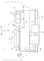
- FIG. 1 is a plan view showing a battery system element arrangement structure in a rear room in an FF plug-in hybrid vehicle of Example 1.
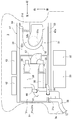
- FIG. It is a side view which shows the battery system element arrangement
- Example 1 shown in the drawings.
- the configuration of the battery cooling structure of the FF plug-in hybrid vehicle (an example of an electric vehicle) according to the first embodiment is divided into “overall system configuration”, “battery element arrangement configuration”, and “battery element cooling structure”. To do.
- FIG. 1 is an overall system diagram showing an FF plug-in hybrid vehicle to which the battery cooling structure of the first embodiment is applied.
- the overall system configuration of the plug-in hybrid vehicle will be described below with reference to FIG.
- the FF plug-in hybrid vehicle includes a front room 1 on the front side of the vehicle on which the power train system elements are mounted, a center room 2 on which a driver and an occupant are seated, and a vehicle rear side on which the battery system elements are mounted.
- the rear room 3 is divided into three spaces.
- the “power train system element” refers to each component element that includes the electronic control system and constitutes the power train system.
- the “battery system element” refers to each component element that includes the electronic control system and constitutes the battery system.
- the rear room 3 may be a luggage room that can accommodate luggage.
- the front room 1 includes a horizontal engine 4, a first clutch 5, a motor / generator 6, a second clutch 7, and a belt type continuously variable transmission 8. It is arranged as a system element.
- the horizontal engine 4 includes an air cleaner 9 and a starter motor 10.
- the output shaft of the belt type continuously variable transmission 8 is drivingly connected to the left and right front wheels via a final reduction gear, a differential gear, and left and right drive shafts (not shown).
- the horizontal engine 4 is an engine disposed in the front room 1 with the crankshaft direction as the vehicle width direction.
- an engine controller 11 that performs various controls related to the horizontal engine 4 is arranged as a component of the engine control system.
- the first clutch 5 is a hydraulic single-plate friction clutch or a multi-plate friction clutch interposed between the horizontal engine 4 and the motor / generator 6, and is engaged / slip-engaged / released by the first clutch oil pressure. Is controlled.
- the motor / generator 6 is a three-phase AC permanent magnet type synchronous motor connected to the transverse engine 4 through the first clutch 5.
- the motor / generator 6 is connected to an inverter 12 through a three-phase AC harness 26 that converts direct current to three-phase alternating current during power running and converts three-phase alternating current to direct current during regeneration.
- a motor controller 13 that outputs a control command to the inverter 12 is disposed as a component of the motor control system.
- the second clutch 7 is a hydraulic single-plate friction clutch or a multi-plate friction clutch interposed between the motor / generator 6 and the left and right front wheels as drive wheels.
- the second clutch 7 is engaged / slip by the second clutch hydraulic pressure. The fastening / release is controlled.
- the belt type continuously variable transmission 8 is speed-controlled to a continuously variable transmission ratio by changing the belt winding diameter by the transmission hydraulic pressure to the primary oil chamber and the secondary oil chamber.
- the belt-type continuously variable transmission 8 has a control valve unit that regulates the line pressure from the pump discharge pressure and generates the first and second clutch hydraulic pressures and the transmission hydraulic pressure using the line pressure as an original pressure.
- a transmission controller 14 that outputs a hydraulic control command to each hydraulic actuator of the control valve unit includes a hydraulic pressure It is arranged as a component of the control system.
- EV mode As typical driving modes with different driving modes by the power train system, there are “EV mode”, “HEV mode” and “WSC mode”.
- the “EV mode” is a mode in which the first clutch 5 is disengaged and the second clutch 7 is engaged to drive the motor.
- the “HEV mode” is a mode in which both the clutches 5 and 7 are engaged to travel.
- the “WSC mode” is a mode in which the first clutch 5 is engaged or released and the second clutch 7 is slip-engaged to travel.
- a brake controller 21 that performs cooperative control of the regenerative braking force and the hydraulic braking force is disposed on the front side of the vehicle and at a position where the brake hydraulic pressure actuator is provided.
- a fuel tank 22 that stores fuel for the horizontally mounted engine 4 is disposed at a position on the rear side of the vehicle and below the floor panel that defines the center room 2. Are connected by a fuel pipe 23.
- the rear room 3 includes a travel battery 31, a first auxiliary battery 32, a second auxiliary battery 33, a joint box 34, a first DC / DC converter 35,
- the second DC / DC converter 36 is arranged as a battery system element.
- a charger 37 and a charging port 38 are additionally arranged as battery system elements in association with the plug-in hybrid vehicle.
- the traveling battery 31 is a secondary battery as a traveling power source, and for example, a laminated lithium ion battery is used.
- the traveling battery 31 has a structure in which a large number of cells connected to each other are stacked to form a battery module, and a plurality of battery modules are arranged in the pack case via gap passages.
- the traveling battery 31 is discharged via the joint box 34 ⁇ the power line harness 39 ⁇ the inverter 12 when the motor / generator 6 performs power running control.
- the motor / generator 6 performs regenerative control
- charging is performed via the inverter 12 ⁇ the power line harness 39 ⁇ the joint box 34.
- the first auxiliary battery 32 is a low-voltage battery mounted as a dedicated power source for the starter motor 10 among in-vehicle auxiliary machines.
- the second auxiliary battery 33 is a low voltage battery mounted as a power source for other auxiliary machines 40 excluding the starter motor 10.
- the reason why the two auxiliary batteries 32 and 33 are installed is to ensure engine start when the starter motor 10 requests engine start. For example, when only one auxiliary battery is mounted, a voltage drop may occur due to simultaneous use of the starter motor 10 and other auxiliary machines 40.
- the joint box 34 is a distribution board in which relay circuits for supplying / cutting off / distributing strong power to the traveling battery 31 are integrated. For example, when the connector plug 41 is connected to the charging port 38 (plug-in) when the vehicle stops at a charging stand or the like (plug-in), the traveling battery 31 is externally charged via the charging port 38 ⁇ the charger 37 ⁇ the joint box 34. If the charge amount of the first auxiliary battery 32 is insufficient, the first auxiliary battery 32 is charged with a part of the charge amount of the traveling battery 31 via the joint box 34 ⁇ the first DC / DC converter 35. The amount is secured. Similarly, if the charging amount of the second auxiliary battery 33 is insufficient, the second auxiliary battery 33 is partially charged by the traveling battery 31 through the joint box 34 ⁇ the second DC / DC converter 36. Charge amount is secured.
- the traveling battery 31, the first DC / DC converter 35, the second DC / DC converter 36, and the charger 37 are all in a pack structure housed in a case that covers the whole, and the air cooling fan units 51, 55, 56 and 57 are provided in each of the storage cases.
- the rear room 3 in which the joint box 34 and the air cooling fan units 51, 55, 56, 57 are arranged performs capacity management, temperature management, etc. of the traveling battery 31 and operation control of the air cooling fan units 51, 55, 56, 57.
- a battery controller 42 for performing the above is disposed as a component of the battery control system.
- an integrated controller 43 that manages the energy consumption of the entire vehicle and has a function for running the vehicle with the highest efficiency is disposed as a component of the integrated control system. Information is exchanged between the integrated controller 43 and the controllers 11, 13, 14, 21, 42 via the CAN communication line 44.
- [Battery element layout] 2 to 4 are a rear view, a plan view, and a side view showing the battery system element arrangement structure in the rear room.
- the arrangement of the battery system elements will be described with reference to FIGS.
- the rear room 3 includes a traveling battery 31, a first auxiliary battery 32 (auxiliary battery), and a second auxiliary battery 33 (auxiliary battery).
- a joint box 34 (electrical component), a first DC / DC converter 35 (electrical component), a second DC / DC converter 36 (electrical component), a charger 37 (electrical component), and a battery controller 42.
- a controller 43 is disposed.
- the traveling battery 31 is disposed in the vehicle front side space of the rear room 3 so as to extend from one end portion to the other end portion in the vehicle width direction.
- This traveling battery 31 includes a lower battery 31a, a middle battery 31b stacked in the same shape as the lower battery 31a, and an upper battery 31c stacked in a position closer to the left side in a smaller shape than the middle battery 31b. It has a three-layer structure. This is a battery of an FF plug-in hybrid vehicle, and a high battery capacity is required in order to ensure a sufficient traveling distance in the electric vehicle mode and meet fuel efficiency requirements.
- the first auxiliary battery 32 and the second auxiliary battery 33 are located on the vehicle rear side with respect to the traveling battery 31 in the rear room 3, and the traveling battery 31. Is arranged at a position overlapping in the longitudinal direction of the vehicle.
- a room floor surface 30 that is a floor surface of the rear room 3 is set through a first floor surface 30a on the vehicle front side and a step wall surface 30b from the first floor surface 30a.
- a second floor surface 30c having a ground clearance lower than that of the surface 30a.
- working is mounted in the 1st floor surface 30a, and the batteries 32 and 33 for both auxiliary machines are mounted in the 2nd floor surface 30c.
- the two auxiliary battery batteries 32 and 33 are arranged side by side in the vehicle width direction at the same vehicle longitudinal direction position.
- the room floor surface 30 has a third floor surface 30e having a ground clearance higher than the first floor surface 30a via a stepped wall surface 30d on the vehicle front side from the first floor surface 30a.
- the step wall surface 30d and the third floor surface 30e are for securing an installation space for the fuel tank 22.
- the joint box 34 is a lateral position of the upper battery 31c having a shape smaller in the vehicle width direction and the front-rear direction than the lower battery 31a and the middle battery 31b. It is arranged at the upper surface position.
- the first DC / DC converter 35, the second DC / DC converter 36, and the charger 37 are electrical components that manage charging / discharging of the battery 31 for traveling and the batteries 32 and 33 for both auxiliary machines. It arrange
- the charger 37 is set to the first frame 45 that is disposed so as to surround the traveling battery 31 including the upper battery 31c. Both DC / DC converters 35, 36 are fixed to the first frame 45 and set side by side in the vehicle front-rear direction on a second frame 46 disposed around the charger 37.
- the first frame 45 is provided on a base frame 47 assembled in a square shape.
- the vehicle width direction frame part 47a of the vehicle rear position of the base frame 47 is arrange
- the battery controller 42 and the integrated controller 43 are two controllers fixed to a frame portion on the front side of the vehicle among the first frames 45 arranged so as to surround the traveling battery 31. Stored in a box.
- the rear room 3 has a battery air cooling fan unit 51, converter air cooling fan units 55 and 56, a charger air cooling fan unit 57, and a cooling structure for battery system elements.
- a battery exhaust duct 58, converter exhaust ducts 59 and 60, and a charger exhaust duct 61 are provided.
- the battery air cooling fan unit 51 is a unit that cools the traveling battery 31 disposed in the rear room 3 with cooling air, and includes a cooling fan 52, a suction duct 53, and a discharge duct 54.
- the cooling fan 52 is an upper end space on one end that is closer to one side in the vehicle width direction in the upper surface space of the traveling battery 31, and is located above the vehicle in the joint box 34. Be placed.
- the cooling fan 52 has a centrifugal fan structure, and includes a scroll casing 52c, a rotary blade 52d disposed in the scroll casing 52c with the vertical direction of the vehicle as a rotation axis direction, and a motor 52e that rotationally drives the rotary blade 52d.
- the scroll casing 52b opens the suction port 52a toward the vehicle upper side, and opens the discharge port 52b toward the vehicle width direction.
- the suction duct 53 has one end connected to the suction port 52a of the scroll casing 52b and the other end opened toward the vehicle lower side.
- the cooling fan 52 When the cooling fan 52 is operated, air is sucked into the suction port 52a of the scroll casing 52b from the duct opening end 53a via the suction duct 53.
- the discharge duct 54 has one end connected to the discharge port 52b of the scroll casing 52b and the other end connected to the cooling air inlet 31d of the battery 31 for traveling.
- the cooling air inlet 31 d is set at a position on the vehicle front side of one end (right end) in the vehicle width direction of the traveling battery 31.
- the cooling air from the cooling fan 52 is introduced into the internal passage of the traveling battery 31 from the cooling air introduction port 31d in the downward direction of the vehicle.
- the converter air cooling fan units 55 and 56 are units for cooling the first DC / DC converter 35 and the second DC / DC converter 36 disposed in the rear room 3 with cooling air. It is comprised.
- the charger air cooling fan unit 57 is a unit for cooling the charger 37 disposed in the rear room 3 with cooling air, and includes a cooling fan and a fan duct.
- the battery exhaust duct 58 has one end connected to the cooling air discharge port 31e of the traveling battery 31 and the other end connected to a drafter opening 3a formed in the vehicle body panel.
- the cooling air discharge port 31 e is set at a position on the vehicle rear side, which is the other end (left end) in the vehicle width direction of the battery 31 for traveling.
- the cooling air whose temperature has increased via the internal passage of the traveling battery 31 is discharged from the cooling air discharge port 31e that opens toward the rear of the vehicle to the drafter opening 3a.
- each of the converter exhaust ducts 59 and 60 is connected to the cooling air discharge port of the first DC / DC converter 35 and the second DC / DC converter 36, and the other end thereof is connected to the charger exhaust duct 61, respectively.
- the charger exhaust duct 61 has one end connected to the cooling air outlet of the charger 37 and the other end connected to the battery exhaust duct 58. That is, as shown in FIG. 3, the four exhaust ducts 58, 59, 60, 61 have a structure sharing a discharge path, all the final discharge ports are draft openings 3a, and an inner panel and an outer panel constituting the vehicle body. The warm air after cooling is discharged to the outside air through the gap space.
- the operation of the battery cooling structure of the FF plug-in hybrid vehicle according to the first embodiment will be described by dividing it into “the arrangement operation of the traveling battery and the auxiliary battery” and “the cooling operation of the battery system element”.
- the traveling battery 31 is disposed in the vehicle front side space of the rear room 3, the vehicle rear side space from the traveling battery 31, and the auxiliary machine at a position overlapping the traveling battery 31 in the vehicle longitudinal direction.
- positions the batteries 32 and 33 for a vehicle was employ
- the auxiliary battery 32, 33 arranged together with the traveling battery 31 in the rear room 3 is used as a buffer member without separately providing a protection member and a buffering member for the rear collision, so that the traveling battery 31 can be rearranged. Protected from impact.
- the room floor surface 30 which is the floor surface of the rear room 3 is set via a first floor surface 30a on the vehicle front side and a step wall surface 30b from the first floor surface 30a, and from the first floor surface 30a. And a second floor surface 30c having a low ground clearance.
- working on the 1st floor surface 30a, and mounts the batteries 32 and 33 for auxiliary machines on the 2nd floor surface 30c was employ
- the function of preventing the auxiliary batteries 32, 33 from moving toward the vehicle front side by the step wall surface 30b is further reinforced by the vehicle width direction frame portion 47a arranged along the step wall surface 30b. Therefore, when the rear impact occurs, the stepped wall surface 30b prevents the auxiliary battery 32, 33 from moving forward of the vehicle toward the travel battery 31, thereby improving the protection performance of the travel battery 31 from the rear impact.
- first DC / DC converter 35, second DC / DC converter 36, and the like electrical components that manage charging / discharging of the traveling battery 31 and the auxiliary batteries 32 and 33 in the space above the traveling battery 31 in the vehicle.
- a configuration in which a charger 37) is arranged was adopted. With this configuration, when the electrical components that manage the charging / discharging of the traveling battery 31 and the auxiliary batteries 32 and 33 are arranged in the front and rear positions of the traveling battery 31, the electrical components occupy the design of the rear room 3. It is necessary to secure space. On the other hand, the space above the vehicle of the battery 31 for driving
- the first auxiliary battery 32 that is the power source of the starter motor 10 of the engine 4 and the second auxiliary battery 33 that is the power source of the auxiliary devices 40 other than the starter motor 10 are used as auxiliary batteries. And having. As shown in FIGS. 2 and 3, the first auxiliary battery 32 and the second auxiliary battery 33 are arranged in the vehicle width direction at the same vehicle longitudinal direction position in the vehicle rear side space than the traveling battery 31. Adopted a configuration to arrange them side by side. With this configuration, the area occupied by the first auxiliary battery 32 and the second auxiliary battery 33 in the vehicle width direction is expanded, and even for offset rear-end collisions on the right and left sides of the rear collision, 2 The two auxiliary batteries 32 and 33 serve as a buffer member for protecting the traveling battery 31. Therefore, by using the two auxiliary battery batteries 32 and 33 arranged side by side in the vehicle width direction in the rear room 3 as a buffer member, the traveling battery 31 is protected against a post-offset impact impact.
- the cooling air whose temperature has risen from the cooling air discharge port 31e to the drafter opening 3a is passed through the battery exhaust duct 58 connected to the cooling air discharge port 31e that opens toward the rear of the vehicle of the traveling battery 31.
- the battery 31 for driving is cooled by discharging.
- the first DC / DC converter 35 and the second DC / DC converter 36 that require cooling in association with the traveling battery 31 being disposed in the space above the vehicle operate the converter air-cooling fan units 55 and 56, thereby cooling air. Is introduced inside the case and takes heat away from the converter circuit. Then, the cooling air whose temperature has risen is discharged to the drafter opening 3a from the converter exhaust ducts 59 and 60, one end of which is connected to the cooling air discharge port of the first DC / DC converter 35 and the second DC / DC converter 36, respectively. .
- both the DC / DC converters are provided by discharging the cooling air whose temperature has risen from the converter exhaust ducts 59 and 60 to the drafter opening 3a via the charger exhaust duct 61 and the battery exhaust duct 58. 35 and 36 are cooled.
- the charger 37 that needs to be cooled due to being disposed in the space above the vehicle of the traveling battery 31 operates the charger air-cooling fan unit 57, so that cooling air is introduced into the case and heat is supplied from the charging circuit. Take away. Then, charging is performed by discharging the cooling air whose temperature has risen from the charger exhaust duct 61, whose one end is connected to the cooling air outlet of the charger 37, via the battery exhaust duct 58 to the draft opening 3 a. The vessel 37 is cooled.
- Example 1 the battery 31 for driving
- the maximum dimension for securing the traveling battery 31 in the rear room 3 is secured as the dimension in the vehicle width direction. Therefore, when the total volume and the height dimension required for the traveling battery 31 are determined, the vehicle longitudinal dimension is shortened.
- the cooling fan 52 is arranged in the upper end space on one end of the upper surface space of the traveling battery 31 that is closer to one side in the vehicle width direction.
- the upper surface space on the other end side where the cooling fan 52 is not disposed is secured as an empty space. Therefore, this empty space can be used as an installation space for electrical components such as the DC / DC converter 35. As a result, cooling of the traveling battery 31 arranged in the rear room 3 is achieved while shortening the vehicle longitudinal direction dimension of the traveling battery 31 and effectively utilizing the upper surface space.
- the cooling fan 52 includes a scroll casing 52c opened with the suction port 52a facing the vehicle upward, and a centrifugal blade having a rotary blade 52d disposed in the scroll casing 52c with the vehicle vertical direction as the rotation axis direction.
- the fan configuration was adopted.
- the centrifugal fan is disposed, generally, the suction opening of the scroll casing is disposed in the vehicle front-rear direction and the vehicle width direction.
- the height of the centrifugal fan (scroll casing) is higher than the diameter of the rotor blades.
- the height of the cooling fan 52 is slightly smaller than the blade width ( ⁇ diameter) of the rotary blade 52d by arranging the suction port 52a of the scroll casing 52c so as to open upward. It only gets higher. Therefore, an increase in dimension in the height direction due to the cooling fan 52 being arranged in the upper surface space of the traveling battery 31 can be suppressed.
- the cooling air introduction port 31 d for introducing the cooling air from the cooling fan 52 into the internal passage of the traveling battery 31 is set at a position on one end in the vehicle width direction of the traveling battery 31 and on the vehicle front side. did. Then, the cooling air discharge port 31e that discharges the cooling air from the cooling fan 52 through the internal passage of the traveling battery 31 is set at a position on the rear side of the vehicle at the other end in the vehicle width direction of the traveling battery 31.
- the configuration was adopted. With this configuration, the flow direction of the cooling air from the cooling air introduction port 31d toward the cooling air discharge port 31e is the diagonal direction of the traveling battery 31, and the traveling of the cooling air flowing through the traveling battery 31 is not biased. The battery 31 flows throughout the battery 31. Therefore, the traveling battery 31 is evenly cooled by the flow of the cooling air in the diagonal direction from the cooling air introduction port 31d toward the cooling air discharge port 31e.
- the electrical components both DC / DC converters 35, 25
- the electrical components for managing charging / discharging such as the traveling battery 31 are arranged in the upper surface space of the traveling battery 31 together with the cooling fan 52. Therefore, the upper surface space of the traveling battery 31 arranged in the rear room 3 is effectively utilized, and the rear room 3 can be made compact.
- a traveling battery 31 and auxiliary batteries 32 and 33 are arranged in a rear room 3 at the rear of the vehicle.
- the battery 31 for traveling is arranged in the vehicle front side space of the rear room 3
- the auxiliary batteries 32 and 33 are disposed in a space behind the traveling battery 31 on the vehicle rear side and overlapping the traveling battery 31 in the vehicle front-rear direction. For this reason, by using the auxiliary batteries 32 and 33 disposed in the rear room 3 together with the traveling battery 31 as buffer members, the traveling battery 31 can be protected from the rear impact.
- a room floor surface 30 which is a floor surface of the rear room 3 is set via a first floor surface 30a on the vehicle front side and a step wall surface 30b from the first floor surface 30a, and the first floor surface 30a A second floor surface 30c having a lower ground clearance,
- the traveling battery 31 is mounted on the first floor surface 30a, and the auxiliary batteries 32 and 33 are mounted on the second floor surface 30c.
- the auxiliary battery 32, 33 is prevented from moving forward by the stepped wall surface 30b toward the traveling battery 31 by the stepped wall surface 30b.
- the protection performance of 31 can be improved.
- the auxiliary battery includes a first auxiliary battery 32 that is a power source for the starter motor 10 of the engine 4 and a second auxiliary battery 33 that is a power source for the auxiliary devices 40 other than the starter motor 10. And having The first auxiliary battery 32 and the second auxiliary battery 33 are arranged side by side in the vehicle width direction at the same vehicle longitudinal direction position in the vehicle rear side space than the traveling battery 31. For this reason, in addition to the effects (1) to (3), the two auxiliary batteries 32 and 33 arranged side by side in the vehicle width direction in the rear room 3 are used as shock absorbers, so that the impact after the offset impact can be prevented. Also, the traveling battery 31 can be protected.
- the battery cooling structure for an electric vehicle has been described based on the first embodiment.
- the specific configuration is not limited to the first embodiment, and the invention according to each claim of the claims. Design changes and additions are permitted without departing from the gist of the present invention.
- Example 1 an example of a battery having a three-layer stacked structure of a lower stage, a middle stage, and an upper stage is shown as the traveling battery 31.
- the battery for traveling may be an example of a battery having a one-stage structure, an example of a battery having a two-stage stacked structure, or the like.
- Example 1 the example which arrange
- the auxiliary battery may be an example in which one battery is arranged.
- positions three or more batteries may be sufficient.
- Example 1 the example which has the 1st floor surface 30a, the level
- the room floor surface which is the floor surface of the rear room, may be an example in which the traveling battery and the auxiliary battery mounting surface are the same flat surface.
- Example 1 shows an example in which the battery element arrangement structure of the present invention is applied to an FF plug-in hybrid vehicle.
- the battery cooling structure for an electric vehicle according to the present invention can also be applied to a hybrid vehicle having no plug-in structure, and further to an electric vehicle using only a motor as a drive source.
- the battery for traveling disposed in the battery room can be applied to an electric vehicle that is cooled by cooling air from a cooling fan.
Landscapes
- Engineering & Computer Science (AREA)
- Mechanical Engineering (AREA)
- Transportation (AREA)
- Life Sciences & Earth Sciences (AREA)
- Sustainable Development (AREA)
- Sustainable Energy (AREA)
- Power Engineering (AREA)
- Chemical & Material Sciences (AREA)
- Combustion & Propulsion (AREA)
- Electric Propulsion And Braking For Vehicles (AREA)
- Arrangement Or Mounting Of Propulsion Units For Vehicles (AREA)
- Hybrid Electric Vehicles (AREA)
Abstract
リアルームに走行用バッテリと共に配置される補機用バッテリを緩衝部材とすることで、走行用バッテリを後突衝撃から保護すること。 車両後部のリアルーム(3)に走行用バッテリ(31)と補機用バッテリ(32,33)を配置した。このFFプラグインハイブリッド車両のバッテリ系要素配置構造において、リアルーム(3)の車両前方側スペースに前記走行用バッテリ(31)を配置した。走行用バッテリ(31)よりも車両後方側スペースであって、走行用バッテリ(31)とは車両前後方向で重なる位置に補機用バッテリ(32,33)を配置した。
Description
本発明は、車両後部のリアルームに走行用バッテリと補機用バッテリを配置した電動車両のバッテリ系要素配置構造に関する。
従来、電動車両のバッテリ系要素配置構造としては、車両後部のリアルームに、走行用バッテリを配置し、該走行用バッテリの上面に補機用バッテリを配置したものが知られている(例えば、特許文献1参照)。
しかしながら、従来の電動車両のバッテリ系要素配置構造にあっては、走行用バッテリの上面に補機用バッテリを配置する縦方向積層配置構造となっている。このため、車両後方から追突される後突時、走行用バッテリと補機用バッテリに対し同時に衝撃力が入力してしまい、走行用バッテリを後突衝撃から保護できない、という問題があった。
本発明は、上記問題に着目してなされたもので、リアルームに走行用バッテリと共に配置される補機用バッテリを緩衝部材とすることで、走行用バッテリを後突衝撃から保護することができる電動車両のバッテリ系要素配置構造を提供することを目的とする。
上記目的を達成するため、本発明は、車両後部のリアルームに走行用バッテリと補機用バッテリを配置した。
この電動車両のバッテリ系要素配置構造において、
前記リアルームの車両前方側スペースに前記走行用バッテリを配置した。
前記走行用バッテリよりも車両後方側スペースであって、前記走行用バッテリとは車両前後方向で重なる位置に前記補機用バッテリを配置した。
この電動車両のバッテリ系要素配置構造において、
前記リアルームの車両前方側スペースに前記走行用バッテリを配置した。
前記走行用バッテリよりも車両後方側スペースであって、前記走行用バッテリとは車両前後方向で重なる位置に前記補機用バッテリを配置した。
よって、後突時、走行用バッテリよりも車両後方側スペースであって、走行用バッテリとは車両前後方向で重なる位置に配置される補機用バッテリが、後突による衝撃力を先に受けて衝撃エネルギーを吸収し、走行用バッテリを保護する緩衝部材になる。
このように、リアルームに走行用バッテリと共に配置される補機用バッテリを緩衝部材とすることで、走行用バッテリを後突衝撃から保護することができる。
このように、リアルームに走行用バッテリと共に配置される補機用バッテリを緩衝部材とすることで、走行用バッテリを後突衝撃から保護することができる。
以下、本発明の電動車両のバッテリ冷却構造を実現する最良の形態を、図面に示す実施例1に基づいて説明する。
まず、構成を説明する。
実施例1のFFプラグインハイブリッド車両(電動車両の一例)のバッテリ冷却構造の構成を、「全体システム構成」、「バッテリ系要素の配置構成」、「バッテリ系要素の冷却構造」に分けて説明する。
実施例1のFFプラグインハイブリッド車両(電動車両の一例)のバッテリ冷却構造の構成を、「全体システム構成」、「バッテリ系要素の配置構成」、「バッテリ系要素の冷却構造」に分けて説明する。
[全体システム構成]
図1は、実施例1のバッテリ冷却構造が適用されたFFプラグインハイブリッド車両を示す全体システム図である。以下、図1に基づいて、プラグインハイブリッド車両の全体システム構成を説明する。
図1は、実施例1のバッテリ冷却構造が適用されたFFプラグインハイブリッド車両を示す全体システム図である。以下、図1に基づいて、プラグインハイブリッド車両の全体システム構成を説明する。
FFプラグインハイブリッド車両は、図1に示すように、パワートレーン系要素を搭載する車両前方側のフロントルーム1と、ドライバや乗員が着座するセンタールーム2と、バッテリ系要素を搭載する車両後方側のリアルーム3と、の3つにスペース区分される。
ここで、「パワートレーン系要素」とは、電子制御系を含みパワートレーン系を構成する各構成要素のことをいう。「バッテリ系要素」とは、電子制御系を含みバッテリ系を構成する各構成要素のことをいう。
なお、リアルーム3は、荷物を収容可能なラッゲージルームであっても良い。
ここで、「パワートレーン系要素」とは、電子制御系を含みパワートレーン系を構成する各構成要素のことをいう。「バッテリ系要素」とは、電子制御系を含みバッテリ系を構成する各構成要素のことをいう。
なお、リアルーム3は、荷物を収容可能なラッゲージルームであっても良い。
前記フロントルーム1には、図1に示すように、横置きエンジン4と、第1クラッチ5と、モータ/ジェネレータ6と、第2クラッチ7と、ベルト式無段変速機8と、がパワートレーン系要素として配置される。なお、横置きエンジン4は、エアクリーナ9とスターターモータ10を有する。また、ベルト式無段変速機8の出力軸は、図外の終減速機と差動ギヤと左右のドライブシャフトを介し、左右の前輪に駆動連結される。
前記横置きエンジン4は、クランク軸方向を車幅方向としてフロントルーム1に配置したエンジンである。横置きエンジン4を配置したフロントルーム1には、横置きエンジン4に関連する様々な制御を行うエンジンコントローラ11が、エンジン制御系の構成要素として配置される。
前記第1クラッチ5は、横置きエンジン4とモータ/ジェネレータ6との間に介装された油圧式の単板摩擦クラッチあるいは多板摩擦クラッチであり、第1クラッチ油圧により締結/スリップ締結/開放が制御される。
前記モータ/ジェネレータ6は、第1クラッチ5を介して横置きエンジン4に連結された三相交流の永久磁石型同期モータである。このモータ/ジェネレータ6には、力行時に直流を三相交流に変換し、回生時に三相交流を直流に変換するインバータ12が、三相交流ハーネス26を介して接続される。モータ/ジェネレータ6を配置したフロントルーム1には、インバータ12に対して制御指令を出力するモータコントローラ13が、モータ制御系の構成要素として配置される。
前記第2クラッチ7は、モータ/ジェネレータ6と駆動輪である左右の前輪との間に介装された油圧式の単板摩擦クラッチあるいは多板摩擦クラッチであり、第2クラッチ油圧により締結/スリップ締結/開放が制御される。
前記ベルト式無段変速機8は、プライマリ油室とセカンダリ油室への変速油圧によりベルトの巻き付き径を変えることで無段階の変速比に変速制御される。ベルト式無段変速機8は、ポンプ吐出圧からライン圧を調圧し、ライン圧を元圧として第1,第2クラッチ油圧及び変速油圧を作り出すコントロールバルブユニットを有する。前記第1,第2クラッチ5,7及びベルト式無段変速機8を配置したフロントルーム1には、コントロールバルブユニットの各油圧アクチュエータに対して油圧制御指令を出力する変速機コントローラ14が、油圧制御系の構成要素として配置される。
前記パワートレーン系による駆動形態が異なる代表的な走行モードとしては、「EVモード」と「HEVモード」と「WSCモード」を有する。「EVモード」は、第1クラッチ5を開放し、第2クラッチ7を締結してモータ走行するモードである。「HEVモード」は、両クラッチ5,7を締結して走行するモードである。「WSCモード」は、第1クラッチ5を締結又は開放し、第2クラッチ7をスリップ締結して走行するモードである。
前記センタールーム2には、図1に示すように、車両前方側であってブレーキ液圧アクチュエータが設けられた位置に、回生制動力と液圧制動力の協調制御を行うブレーキコントローラ21が配置される。また、車両後方側の位置であって、センタールーム2を画成するフロアパネルの下側位置に、横置きエンジン4への燃料を蓄える燃料タンク22が配置され、横置きエンジン4と燃料タンク22は、燃料パイプ23にて接続される。
前記リアルーム3には、図1に示すように、走行用バッテリ31と、第1補機用バッテリ32と、第2補機用バッテリ33と、ジョイントボックス34と、第1DC/DCコンバータ35と、第2DC/DCコンバータ36と、がバッテリ系要素として配置される。なお、リアルーム3には、プラグインハイブリッド車両であることに伴い、充電器37と充電ポート38がバッテリ系要素として追加配置される。
前記走行用バッテリ31は、走行用電源としての二次電池であり、例えば、ラミネート型リチウムイオンバッテリが用いられる。この走行用バッテリ31は、互いに接続した多数のセルを積層してバッテリモジュールとし、複数のバッテリモジュールをパックケース内に隙間通路を介して配置した構造としている。走行用バッテリ31は、モータ/ジェネレータ6が力行制御を行うとき、ジョイントボックス34→電力線ハーネス39→インバータ12を経由して放電する。一方、モータ/ジェネレータ6が回生制御を行うとき、インバータ12→電力線ハーネス39→ジョイントボックス34を経由して充電する。
前記第1補機用バッテリ32は、車載の補機類のうちスターターモータ10の専用電源として搭載した低電圧バッテリである。前記第2補機用バッテリ33は、スターターモータ10を除く他の補機類40の電源として搭載した低電圧バッテリである。ここで、2つの補機用バッテリ32,33を搭載している理由は、スターターモータ10によるエンジン始動要求時にエンジン始動を確保するためである。例えば、1つの補機用バッテリのみを搭載した場合には、スターターモータ10と他の補機類40との同時使用等を原因として電圧降下が発生することがあることによる。
前記ジョイントボックス34は、走行用バッテリ31に対する強電の供給/遮断/分配等を行うリレー回路を集約させた分電盤である。例えば、充電スタンド等での停車時にコネクタプラグ41を充電ポート38に接続すると(プラグイン)、充電ポート38→充電器37→ジョイントボックス34を経由し、走行用バッテリ31が外部充電される。また、第1補機用バッテリ32の充電量が不足すると、ジョイントボックス34→第1DC/DCコンバータ35を経由し、走行用バッテリ31の充電量の一部で第1補機用バッテリ32の充電量が確保される。同様に、第2補機用バッテリ33の充電量が不足すると、ジョイントボックス34→第2DC/DCコンバータ36を経由し、走行用バッテリ31の充電量の一部で第2補機用バッテリ33の充電量が確保される。
前記走行用バッテリ31と前記第1DC/DCコンバータ35と前記第2DC/DCコンバータ36と前記充電器37は、何れも全体を覆うケースに収納されたパック構造であり、空冷ファンユニット51,55,56,57が収納ケースのそれぞれに設けられている。前記ジョイントボックス34及び空冷ファンユニット51,55,56,57を配置したリアルーム3には、走行用バッテリ31の容量管理や温度管理等を行うと共に空冷ファンユニット51,55,56,57の動作制御を行うバッテリコントローラ42が、バッテリ制御系の構成要素として配置される。
前記リアルーム3には、車両全体の消費エネルギーを管理し、最高効率で車両を走らせるための機能を担う統合コントローラ43が、統合制御系の構成要素として配置される。なお、統合コントローラ43と、各コントローラ11,13,14,21,42は、CAN通信線44を介して情報交換される。
[バッテリ系要素の配置構成]
図2~図4は、リアルーム内でのバッテリ系要素配置構造を示す背面図、平面図、側面図である。以下、図2~図4に基づき、バッテリ系要素の配置構成を説明する。
図2~図4は、リアルーム内でのバッテリ系要素配置構造を示す背面図、平面図、側面図である。以下、図2~図4に基づき、バッテリ系要素の配置構成を説明する。
前記リアルーム3には、図2~図4に示すように、走行用バッテリ31と、第1補機用バッテリ32(補機用バッテリ)と、第2補機用バッテリ33(補機用バッテリ)と、ジョイントボックス34(電装部品)と、第1DC/DCコンバータ35(電装部品)と、第2DC/DCコンバータ36(電装部品)と、充電器37(電装部品)と、バッテリコントローラ42と、統合コントローラ43と、が配置されている。
前記走行用バッテリ31は、図2~図4に示すように、リアルーム3の車両前方側スペースに、車幅方向の一端部から他端部まで延設して配置されている。この走行用バッテリ31は、下段バッテリ31aと、該下段バッテリ31aと同形状で積み重ねた中段バッテリ31bと、該中段バッテリ31bよりも小さい形状で左側に寄せた位置に積み重ねた上段バッテリ31cと、の3層構造により構成されている。これは、FFプラグインハイブリッド車のバッテリであり、電気自動車モードでの走行距離を十分に確保し、燃費性能要求に応えるため、高いバッテリ容量が要求されることによる。
前記第1補機用バッテリ32と前記第2補機用バッテリ33は、図2~図4に示すように、リアルーム3の走行用バッテリ31よりも車両後方側スペースであって、走行用バッテリ31とは車両前後方向で重なる位置に配置される。リアルーム3の床面であるルームフロア面30は、図4に示すように、車両前方側の第1フロア面30aと、該第1フロア面30aから段差壁面30bを介して設定され、第1フロア面30aより地上高を低くした第2フロア面30cと、を有する。そして、走行用バッテリ31を第1フロア面30aに搭載し、両補機用バッテリ32,33を第2フロア面30cに搭載している。両補機用バッテリ32,33は、図3に示すように、同じ車両前後方向位置に、車幅方向に2つを並べて配置されている。なお、ルームフロア面30は、図4に示すように、第1フロア面30aより車両前方側に段差壁面30dを介し、第1フロア面30aより地上高を高くした第3フロア面30eを有する。この段差壁面30dと第3フロア面30eは、燃料タンク22の設置スペースを確保するためである。
前記ジョイントボックス34は、図2及び図3に示すように、下段バッテリ31aと中段バッテリ31bに比べて車幅方向と前後方向に小さい形状の上段バッテリ31cの横位置であって、中段バッテリ31bの上面位置に配置される。
前記第1DC/DCコンバータ35と前記第2DC/DCコンバータ36と前記充電器37は、走行用バッテリ31と両補機用バッテリ32,33の充放電を管理する電装部品であり、上段バッテリ31cの車両上方スペースに積層状態で配置される。充電器37は、上段バッテリ31cを含む走行用バッテリ31を囲って配置される第1フレーム45に設定される。両DC/DCコンバータ35,36は、第1フレーム45に固定され、充電器37を囲って配置される第2フレーム46に車両前後方向に並べて設定される。
なお、第1フレーム45は、方形状に組んだベースフレーム47に設けられる。そして、ベースフレーム47の車両後方位置の車幅方向フレーム部47aは、段差壁面30bの上面に沿って走行用バッテリ31と両補機用バッテリ32,33の車両前後方向の中間位置に配置される。
なお、第1フレーム45は、方形状に組んだベースフレーム47に設けられる。そして、ベースフレーム47の車両後方位置の車幅方向フレーム部47aは、段差壁面30bの上面に沿って走行用バッテリ31と両補機用バッテリ32,33の車両前後方向の中間位置に配置される。
前記バッテリコントローラ42と前記統合コントローラ43は、図3及び図4に示すように、走行用バッテリ31を囲って配置される第1フレーム45のうち、車両前方側のフレーム部に固定した2つのコントローラボックスに収納配置される。
[バッテリ系要素の冷却構造]
前記リアルーム3には、バッテリ系要素の冷却構造として、図2及び図3に示すように、バッテリ用空冷ファンユニット51と、コンバータ用空冷ファンユニット55,56と、充電器用空冷ファンユニット57と、バッテリ用排気ダクト58と、コンバータ用排気ダクト59,60と、充電器用排気ダクト61と、が設けられる。
前記リアルーム3には、バッテリ系要素の冷却構造として、図2及び図3に示すように、バッテリ用空冷ファンユニット51と、コンバータ用空冷ファンユニット55,56と、充電器用空冷ファンユニット57と、バッテリ用排気ダクト58と、コンバータ用排気ダクト59,60と、充電器用排気ダクト61と、が設けられる。
前記バッテリ用空冷ファンユニット51は、リアルーム3に配置した走行用バッテリ31を冷却風により空冷するユニットで、冷却ファン52と、吸込みダクト53と、吐出ダクト54と、を有して構成される。
前記冷却ファン52は、図2及び図3に示すように、走行用バッテリ31の上面スペースのうち、車幅方向の片側に寄った一端側上面スペースであって、ジョイントボックス34の車両上方位置に配置される。この冷却ファン52は、遠心ファン構造であり、スクロールケーシング52cと、車両上下方向を回転軸方向としてスクロールケーシング52c内に配置した回転翼52dと、該回転翼52dを回転駆動させるモータ52eと、を有する。スクロールケーシング52bは、吸込み口52aを車両上方に向けて開口し、吐出口52bを車幅方向に向けて開口している。
前記吸込みダクト53は、図2及び図3に示すように、一端がスクロールケーシング52bの吸込み口52aに連結され、他端が車両下方に向けて開口している。冷却ファン52の作動時には、ダクト開口端53aから吸込みダクト53を経由してスクロールケーシング52bの吸込み口52aに空気を吸い込む。
前記吐出ダクト54は、図2及び図3に示すように、一端がスクロールケーシング52bの吐出口52bに連結され、他端が走行用バッテリ31の冷却風導入口31dに連結される。冷却風導入口31dは、図3に示すように、走行用バッテリ31の車幅方向一端部(右端部)であって車両前方側の位置に設定される。冷却ファン52の作動時には、冷却ファン52からの冷却風を、冷却風導入口31dから車両下方向に向かって走行用バッテリ31の内部通路に導入する。
前記コンバータ用空冷ファンユニット55,56は、図3に示すように、リアルーム3に配置した第1DC/DCコンバータ35と第2DC/DCコンバータ36を冷却風により空冷するユニットで、冷却ファンとファンダクトを有して構成される。
前記充電器用空冷ファンユニット57は、図3に示すように、リアルーム3に配置した充電器37を冷却風により空冷するユニットで、冷却ファンとファンダクトを有して構成される。
前記バッテリ用排気ダクト58は、一端が走行用バッテリ31の冷却風排出口31eに連結され、他端が車体パネルに形成したドラフター開口3aに連結される。冷却風排出口31eは、図2に示すように、走行用バッテリ31の車幅方向他端部(左端部)であって車両後方側の位置に設定される。冷却ファン52の作動時には、走行用バッテリ31の内部通路を経由して温度が上昇した冷却風を、車両後方に向かって開口する冷却風排出口31eからドラフター開口3aへと排出する。
前記コンバータ用排気ダクト59,60は、一端がそれぞれ第1DC/DCコンバータ35と第2DC/DCコンバータ36の冷却風排出口に連結され、他端がそれぞれ充電器用排気ダクト61に連結される。
前記充電器用排気ダクト61は、一端が充電器37の冷却風排出口に連結され、他端がバッテリ用排気ダクト58に連結される。すなわち、4つの排気ダクト58,59,60,61は、図3に示すように、排出経路を共用する構造とし、全ての最終排出口をドラフター開口3aとし、車体を構成するインナーパネルとアウターパネルの隙間空間を介して冷却後の暖まった空気を外気へ排出するようにしている。
次に、作用を説明する。
実施例1のFFプラグインハイブリッド車両のバッテリ冷却構造における作用を、「走行用バッテリと補機用バッテリの配置作用」、「バッテリ系要素の冷却作用」に分けて説明する。
実施例1のFFプラグインハイブリッド車両のバッテリ冷却構造における作用を、「走行用バッテリと補機用バッテリの配置作用」、「バッテリ系要素の冷却作用」に分けて説明する。
[走行用バッテリと補機用バッテリの配置作用]
走行用バッテリ31と補機用バッテリ32,33をリアルーム3内に配置する場合、高圧バッテリである走行用バッテリ31の後突に対する保護対策が必要である。以下、これを反映する走行用バッテリ31と補機用バッテリ32,33の配置作用を説明する。
走行用バッテリ31と補機用バッテリ32,33をリアルーム3内に配置する場合、高圧バッテリである走行用バッテリ31の後突に対する保護対策が必要である。以下、これを反映する走行用バッテリ31と補機用バッテリ32,33の配置作用を説明する。
実施例1では、リアルーム3の車両前方側スペースに走行用バッテリ31を配置し、走行用バッテリ31よりも車両後方側スペースであって、走行用バッテリ31とは車両前後方向で重なる位置に補機用バッテリ32,33を配置する構成を採用した。
この構成により、後突時、車両前方側に押し込む衝撃力が作用して車体が変形すると、補機用バッテリ32,33が、後突による衝撃力を走行用バッテリ31よりも先に受けて衝撃エネルギーを吸収する。すなわち、補機用バッテリ32,33が、走行用バッテリ31を保護する緩衝部材になる。
したがって、後突に対する保護部材や緩衝部材を別途設けることなく、リアルーム3に走行用バッテリ31と共に配置される補機用バッテリ32,33を緩衝部材として利用することで、走行用バッテリ31が後突衝撃から保護される。
この構成により、後突時、車両前方側に押し込む衝撃力が作用して車体が変形すると、補機用バッテリ32,33が、後突による衝撃力を走行用バッテリ31よりも先に受けて衝撃エネルギーを吸収する。すなわち、補機用バッテリ32,33が、走行用バッテリ31を保護する緩衝部材になる。
したがって、後突に対する保護部材や緩衝部材を別途設けることなく、リアルーム3に走行用バッテリ31と共に配置される補機用バッテリ32,33を緩衝部材として利用することで、走行用バッテリ31が後突衝撃から保護される。
実施例1では、リアルーム3の床面であるルームフロア面30を、車両前方側の第1フロア面30aと、第1フロア面30aから段差壁面30bを介して設定され、第1フロア面30aより地上高を低くした第2フロア面30cと、を有する構成とした。そして、走行用バッテリ31を第1フロア面30aに搭載し、補機用バッテリ32,33を第2フロア面30cに搭載する構成を採用した。
この構成により、後突時、補機用バッテリ32,33が車両前方側へ移動しても、段差壁面30bに当接して移動が阻止され、段差壁面30bに挟まれた補機用バッテリ32,33のみが変形したり損傷したりする。なお、段差壁面30bによる補機用バッテリ32,33の車両前方側への移動阻止機能は、段差壁面30bに沿って配置された車幅方向フレーム部47aによりさらに補強される。
したがって、後突時、段差壁面30bにより補機用バッテリ32,33が走行用バッテリ31に向かう車両前方移動を阻止することで、後突衝撃からの走行用バッテリ31の保護性能が向上される。
この構成により、後突時、補機用バッテリ32,33が車両前方側へ移動しても、段差壁面30bに当接して移動が阻止され、段差壁面30bに挟まれた補機用バッテリ32,33のみが変形したり損傷したりする。なお、段差壁面30bによる補機用バッテリ32,33の車両前方側への移動阻止機能は、段差壁面30bに沿って配置された車幅方向フレーム部47aによりさらに補強される。
したがって、後突時、段差壁面30bにより補機用バッテリ32,33が走行用バッテリ31に向かう車両前方移動を阻止することで、後突衝撃からの走行用バッテリ31の保護性能が向上される。
実施例1では、走行用バッテリ31の車両上方スペースに、走行用バッテリ31と補機用バッテリ32,33の充放電を管理する電装部品(第1DC/DCコンバータ35,第2DC/DCコンバータ36,充電器37)を配置する構成を採用した。
この構成により、走行用バッテリ31と補機用バッテリ32,33の充放電を管理する電装部品を走行用バッテリ31の前後位置に平面的に配置する場合、リアルーム3の設計において電装部品が占有するスペース分を確保することが必要となる。
これに対し、電装部品の立体的な配置により、リアルーム3に配置された走行用バッテリ31の車両上方スペースが有効に活用され、リアルーム3のコンパクト化が達成される。
この構成により、走行用バッテリ31と補機用バッテリ32,33の充放電を管理する電装部品を走行用バッテリ31の前後位置に平面的に配置する場合、リアルーム3の設計において電装部品が占有するスペース分を確保することが必要となる。
これに対し、電装部品の立体的な配置により、リアルーム3に配置された走行用バッテリ31の車両上方スペースが有効に活用され、リアルーム3のコンパクト化が達成される。
実施例1では、補機用バッテリとして、エンジン4のスターターモータ10の電源である第1補機用バッテリ32と、スターターモータ10以外の補機類40の電源である第2補機用バッテリ33と、を有する。そして、第1補機用バッテリ32と第2補機用バッテリ33は、図2及び図3に示すように、走行用バッテリ31よりも車両後方側スペースの同じ車両前後方向位置に、車幅方向に並べて配置する構成を採用した。
この構成により、第1補機用バッテリ32と第2補機用バッテリ33による車幅方向の占有領域が拡大し、後突のうち、右側や左側に寄ったオフセット後突に対しても、2つの補機用バッテリ32,33が、走行用バッテリ31を保護する緩衝部材になる。
したがって、リアルーム3に車幅方向に並べて配置される2つの補機用バッテリ32,33を緩衝部材として利用することで、オフセット後突衝撃に対しても走行用バッテリ31が保護される。
この構成により、第1補機用バッテリ32と第2補機用バッテリ33による車幅方向の占有領域が拡大し、後突のうち、右側や左側に寄ったオフセット後突に対しても、2つの補機用バッテリ32,33が、走行用バッテリ31を保護する緩衝部材になる。
したがって、リアルーム3に車幅方向に並べて配置される2つの補機用バッテリ32,33を緩衝部材として利用することで、オフセット後突衝撃に対しても走行用バッテリ31が保護される。
[バッテリ系要素の冷却作用]
走行用バッテリ31は、高温になるとバッテリ性能が低下することで、高いバッテリ性能を維持するために冷却することが必要である。以下、これを反映するバッテリ系要素の冷却作用を説明する。
走行用バッテリ31は、高温になるとバッテリ性能が低下することで、高いバッテリ性能を維持するために冷却することが必要である。以下、これを反映するバッテリ系要素の冷却作用を説明する。
走行用バッテリ31の冷却作用を説明すると、冷却ファン52の回転翼52dをモータ52eにより回転駆動させると、スクロールケーシング52bの吸込み口52aに連結されている吸込みダクト53からリアルーム3内の空気を吸い込む。そして、冷却ファン52からの冷却風を、スクロールケーシング52bの吐出口52bに連結されている吐出ダクト54から走行用バッテリ31の冷却風導入口31dに吐出する。これにより、冷却風導入口31dから車両下方向に向かって走行用バッテリ31の内部通路に、冷却ファン52からの冷却風が導入され、走行用バッテリ31の内部通路を対角線方向に向かって通過するときに各バッテリセルから熱を奪う。そして、走行用バッテリ31の車両後方に向かって開口する冷却風排出口31eに連結されたバッテリ用排気ダクト58を経由し、温度が上昇した冷却風を、冷却風排出口31eからドラフター開口3aへと排出することで、走行用バッテリ31が冷却される。
走行用バッテリ31の車両上方スペースに配置されていることに伴い冷却を要する第1DC/DCコンバータ35と第2DC/DCコンバータ36は、コンバータ用空冷ファンユニット55,56を作動させることで、冷却風がケース内部に導入され、コンバータ回路から熱を奪う。そして、一端がそれぞれ第1DC/DCコンバータ35と第2DC/DCコンバータ36の冷却風排出口に連結されたコンバータ用排気ダクト59,60から、温度が上昇した冷却風をドラフター開口3aへと排出する。このとき、コンバータ用排気ダクト59,60からは、充電器用排気ダクト61とバッテリ用排気ダクト58を経由し、温度が上昇した冷却風をドラフター開口3aへと排出することで、両DC/DCコンバータ35,36が冷却される。
走行用バッテリ31の車両上方スペースに配置されていることに伴い冷却を要する充電器37は、充電器用空冷ファンユニット57を作動させることで、冷却風がケース内部に導入され、充電回路から熱を奪う。そして、一端が充電器37の冷却風排出口に連結された充電器用排気ダクト61から、バッテリ用排気ダクト58を経由し、温度が上昇した冷却風をドラフター開口3aへと排出することで、充電器37が冷却される。
実施例1では、上面に冷却ファン52を配置した走行用バッテリ31を、リアルーム3の車幅方向の一端部から他端部まで延設して配置した。この構成を採用したことで、図2及び図3に示すように、走行用バッテリ31の車幅方向寸法としてリアルーム3に配置するのに最大限の寸法が確保される。したがって、走行用バッテリ31として要求される全容積と高さ寸法が決まっている場合、車両前後方向寸法が短縮化される。
さらに、走行用バッテリ31の上面スペースのうち、車幅方向の片側に寄った一端側上面スペースに冷却ファン52を配置した。この構成を採用したことで、図2及び図3に示すように、冷却ファン52が配置されない他端側上面スペースが空きスペースとして確保される。したがって、この空きスペースを、DC/DCコンバータ35等の電装部品の設置スペースとして利用可能である。
この結果、走行用バッテリ31の車両前後方向寸法の短縮化と上面スペースの有効活用を図りながら、リアルーム3に配置された走行用バッテリ31の冷却が達成される。
さらに、走行用バッテリ31の上面スペースのうち、車幅方向の片側に寄った一端側上面スペースに冷却ファン52を配置した。この構成を採用したことで、図2及び図3に示すように、冷却ファン52が配置されない他端側上面スペースが空きスペースとして確保される。したがって、この空きスペースを、DC/DCコンバータ35等の電装部品の設置スペースとして利用可能である。
この結果、走行用バッテリ31の車両前後方向寸法の短縮化と上面スペースの有効活用を図りながら、リアルーム3に配置された走行用バッテリ31の冷却が達成される。
実際例1では、冷却ファン52を、吸込み口52aを車両上方に向けて開口したスクロールケーシング52cと、車両上下方向を回転軸方向とし、スクロールケーシング52c内に配置した回転翼52dと、を有する遠心ファンとする構成を採用した。
遠心ファンを配置する場合、一般的には、スクロールケーシングの吸込み口を車両前後方向や車幅方向に開口して配置される。しかし、この場合、遠心ファン(スクロールケーシング)の高さが、回転翼の直径よりも高くなる。
これに対し、スクロールケーシング52cの吸込み口52aを車両上方に向けて開口する配置とすることで、冷却ファン52(スクロールケーシング52c)の高さが回転翼52dの翼幅(<直径)よりも少し高くなるだけである。
したがって、走行用バッテリ31の上面スペースに冷却ファン52を配置することによる高さ方向の寸法増大が抑えられる。
遠心ファンを配置する場合、一般的には、スクロールケーシングの吸込み口を車両前後方向や車幅方向に開口して配置される。しかし、この場合、遠心ファン(スクロールケーシング)の高さが、回転翼の直径よりも高くなる。
これに対し、スクロールケーシング52cの吸込み口52aを車両上方に向けて開口する配置とすることで、冷却ファン52(スクロールケーシング52c)の高さが回転翼52dの翼幅(<直径)よりも少し高くなるだけである。
したがって、走行用バッテリ31の上面スペースに冷却ファン52を配置することによる高さ方向の寸法増大が抑えられる。
実施例1では、冷却ファン52からの冷却風を走行用バッテリ31の内部通路に導入する冷却風導入口31dを、走行用バッテリ31の車幅方向一端部であって車両前方側の位置に設定した。そして、冷却ファン52からの冷却風を走行用バッテリ31の内部通路を介して排出する冷却風排出口31eを、走行用バッテリ31の車幅方向他端部であって車両後方側の位置に設定した構成を採用した。
この構成により、冷却風導入口31dから冷却風排出口31eへ向かう冷却風の流れ方向は、走行用バッテリ31の対角線方向となり、走行用バッテリ31内を流れる冷却風の流れが偏ることなく、走行用バッテリ31内を全体にわたって流れる。
したがって、冷却風導入口31dから冷却風排出口31eへ向かう対角線方向の冷却風の流れにより、走行用バッテリ31が均等に冷却される。
この構成により、冷却風導入口31dから冷却風排出口31eへ向かう冷却風の流れ方向は、走行用バッテリ31の対角線方向となり、走行用バッテリ31内を流れる冷却風の流れが偏ることなく、走行用バッテリ31内を全体にわたって流れる。
したがって、冷却風導入口31dから冷却風排出口31eへ向かう対角線方向の冷却風の流れにより、走行用バッテリ31が均等に冷却される。
実施例1では、走行用バッテリ31の上面スペースのうち、冷却ファン52を配置した一端側上面スペースとは車幅方向に反対側の他端側上面スペースに電装部品(両DC/DCコンバータ35,36、充電器37)を配置する構成を採用した。
この構成により、走行用バッテリ31等の充放電を管理する電装部品が、冷却ファン52と共に、走行用バッテリ31の上面スペースに配置されることになる。
したがって、リアルーム3に配置された走行用バッテリ31の上面スペースが有効に活用され、リアルーム3のコンパクト化が達成される。
この構成により、走行用バッテリ31等の充放電を管理する電装部品が、冷却ファン52と共に、走行用バッテリ31の上面スペースに配置されることになる。
したがって、リアルーム3に配置された走行用バッテリ31の上面スペースが有効に活用され、リアルーム3のコンパクト化が達成される。
次に、効果を説明する。
実施例1のFFプラグインハイブリッド車両のバッテリ冷却構造にあっては、下記に列挙する効果を得ることができる。
実施例1のFFプラグインハイブリッド車両のバッテリ冷却構造にあっては、下記に列挙する効果を得ることができる。
(1) 車両後部のリアルーム3に走行用バッテリ31と補機用バッテリ32,33を配置した電動車両(FFプラグインハイブリッド車両)のバッテリ系要素配置構造において、
前記リアルーム3の車両前方側スペースに前記走行用バッテリ31を配置し、
前記走行用バッテリ31よりも車両後方側スペースであって、前記走行用バッテリ31とは車両前後方向で重なる位置に前記補機用バッテリ32,33を配置した。
このため、リアルーム3に走行用バッテリ31と共に配置される補機用バッテリ32,33を緩衝部材とすることで、走行用バッテリ31を後突衝撃から保護することができる。
前記リアルーム3の車両前方側スペースに前記走行用バッテリ31を配置し、
前記走行用バッテリ31よりも車両後方側スペースであって、前記走行用バッテリ31とは車両前後方向で重なる位置に前記補機用バッテリ32,33を配置した。
このため、リアルーム3に走行用バッテリ31と共に配置される補機用バッテリ32,33を緩衝部材とすることで、走行用バッテリ31を後突衝撃から保護することができる。
(2) 前記リアルーム3の床面であるルームフロア面30は、車両前方側の第1フロア面30aと、該第1フロア面30aから段差壁面30bを介して設定され、前記第1フロア面30aより地上高を低くした第2フロア面30cと、を有し、
前記走行用バッテリ31を前記第1フロア面30aに搭載し、前記補機用バッテリ32,33を前記第2フロア面30cに搭載した。
このため、(1)の効果に加え、後突時、段差壁面30bにより補機用バッテリ32,33が走行用バッテリ31に向かう車両前方移動を阻止することで、後突衝撃からの走行用バッテリ31の保護性能を向上することができる。
前記走行用バッテリ31を前記第1フロア面30aに搭載し、前記補機用バッテリ32,33を前記第2フロア面30cに搭載した。
このため、(1)の効果に加え、後突時、段差壁面30bにより補機用バッテリ32,33が走行用バッテリ31に向かう車両前方移動を阻止することで、後突衝撃からの走行用バッテリ31の保護性能を向上することができる。
(3) 前記走行用バッテリ31の車両上方スペースに、前記走行用バッテリ31と前記補機用バッテリ32,33の充放電を管理する電装部品(ジョイントボックス34、両DC/DCコンバータ35,36、充電器37)を配置した。
このため、(1)又は(2)の効果に加え、リアルーム3に配置された走行用バッテリ31の車両上方スペースが電装部品(ジョイントボックス34、両DC/DCコンバータ35,36、充電器37)の配置スペースとして有効に活用され、リアルーム3のコンパクト化を達成することができる。
このため、(1)又は(2)の効果に加え、リアルーム3に配置された走行用バッテリ31の車両上方スペースが電装部品(ジョイントボックス34、両DC/DCコンバータ35,36、充電器37)の配置スペースとして有効に活用され、リアルーム3のコンパクト化を達成することができる。
(4) 前記補機用バッテリは、エンジン4のスターターモータ10の電源である第1補機用バッテリ32と、前記スターターモータ10以外の補機類40の電源である第2補機用バッテリ33と、を有し、
前記第1補機用バッテリ32と前記第2補機用バッテリ33は、前記走行用バッテリ31よりも車両後方側スペースの同じ車両前後方向位置に、車幅方向に並べて配置した。
このため、(1)~(3)の効果に加え、リアルーム3に車幅方向に並べて配置される2つの補機用バッテリ32,33を緩衝部材とすることで、オフセット後突衝撃に対しても走行用バッテリ31を保護することができる。
前記第1補機用バッテリ32と前記第2補機用バッテリ33は、前記走行用バッテリ31よりも車両後方側スペースの同じ車両前後方向位置に、車幅方向に並べて配置した。
このため、(1)~(3)の効果に加え、リアルーム3に車幅方向に並べて配置される2つの補機用バッテリ32,33を緩衝部材とすることで、オフセット後突衝撃に対しても走行用バッテリ31を保護することができる。
以上、本発明の電動車両のバッテリ冷却構造を実施例1に基づき説明してきたが、具体的な構成については、この実施例1に限られるものではなく、請求の範囲の各請求項に係る発明の要旨を逸脱しない限り、設計の変更や追加等は許容される。
実施例1では、走行用バッテリ31として、下段・中段・上段の3段積層構造によるバッテリの例を示した。しかし、走行用バッテリとしては、1段構造によるバッテリの例でも良いし、2段積層構造によるバッテリの例、等であっても良い。
実施例1では、補機用バッテリとして、第1補機用バッテリ32と第2補機用バッテリ33を配置する例を示した。しかし、補機用バッテリとしては、1つのバッテリを配置する例であっても良い。また、3つ以上のバッテリを配置する例であっても良い。
実施例1では、リアルームの床面であるルームフロア面30として、第1フロア面30aと段差壁面30bと第2フロア面30cを有する例を示した。しかし、リアルームの床面であるルームフロア面としては、走行用バッテリと補機用バッテリの搭載面が同じ平面によるフロア面とする例であっても良い。
実施例1では、走行用バッテリ31の車両上方スペースに、走行用バッテリ31と補機用バッテリ32,33の充放電を管理する電装部品を配置する例を示した。しかし、走行用バッテリ31の車両上方スペースに、電装部品を配置しない例としても良い。
実施例1では、本発明のバッテリ系要素配置構造をFFプラグインハイブリッド車両に適用する例を示した。しかし、本発明の電動車両のバッテリ冷却構造は、プラグイン構造を持たないハイブリッド車両、さらに、モータのみを駆動源とする電気自動車に対しても適用することができる。要するに、バッテリルームに配置した走行用バッテリを、冷却ファンからの冷却風により冷却する電動車両に適用できる。
本出願は、2012年1月17日に日本国特許庁に出願された特願2012-6668に基づいて優先権を主張し、その全ての開示は完全に本明細書で参照により組み込まれる。
Claims (4)
- 車両後部のリアルームに走行用バッテリと補機用バッテリを配置した電動車両のバッテリ系要素配置構造において、
前記リアルームの車両前方側スペースに前記走行用バッテリを配置し、
前記走行用バッテリよりも車両後方側スペースであって、前記走行用バッテリとは車両前後方向で重なる位置に前記補機用バッテリを配置した
ことを特徴とする電動車両のバッテリ系要素配置構造。 - 請求項1に記載された電動車両のバッテリ系要素配置構造において、
前記リアルームの床面であるルームフロア面は、車両前方側の第1フロア面と、該第1フロア面から段差壁面を介して設定され、前記第1フロア面より地上高を低くした第2フロア面と、を有し、
前記走行用バッテリを前記第1フロア面に搭載し、前記補機用バッテリを前記第2フロア面に搭載した
ことを特徴とする電動車両のバッテリ系要素配置構造。 - 請求項1又は2に記載された電動車両のバッテリ系要素配置構造において、
前記走行用バッテリの車両上方スペースに、前記走行用バッテリと前記補機用バッテリの充放電を管理する電装部品を配置した
ことを特徴とする電動車両のバッテリ系要素配置構造。 - 請求項1から3までの何れか1項に記載された電動車両のバッテリ系要素配置構造において、
前記補機用バッテリは、エンジンのスターターモータの電源である第1補機用バッテリと、前記スターターモータ以外の補機類の電源である第2補機用バッテリと、を有し、
前記第1補機用バッテリと前記第2補機用バッテリは、前記走行用バッテリよりも車両後方側スペースの同じ車両前後方向位置に、車幅方向に並べて配置した
ことを特徴とする電動車両のバッテリ系要素配置構造。
Priority Applications (3)
| Application Number | Priority Date | Filing Date | Title |
|---|---|---|---|
| US14/370,275 US9090218B2 (en) | 2012-01-17 | 2013-01-16 | Battery system component layout structure for electrically driven vehicle |
| EP13738438.4A EP2805855B1 (en) | 2012-01-17 | 2013-01-16 | Battery system element arrangement structure for electric vehicle |
| CN201380004482.1A CN104024056B (zh) | 2012-01-17 | 2013-01-16 | 电动车辆的蓄电池系统要素配置结构 |
Applications Claiming Priority (2)
| Application Number | Priority Date | Filing Date | Title |
|---|---|---|---|
| JP2012006668A JP6089403B2 (ja) | 2012-01-17 | 2012-01-17 | 電動車両のバッテリ系要素配置構造 |
| JP2012-006668 | 2012-01-17 |
Publications (1)
| Publication Number | Publication Date |
|---|---|
| WO2013108762A1 true WO2013108762A1 (ja) | 2013-07-25 |
Family
ID=48799187
Family Applications (1)
| Application Number | Title | Priority Date | Filing Date |
|---|---|---|---|
| PCT/JP2013/050597 Ceased WO2013108762A1 (ja) | 2012-01-17 | 2013-01-16 | 電動車両のバッテリ系要素配置構造 |
Country Status (5)
| Country | Link |
|---|---|
| US (1) | US9090218B2 (ja) |
| EP (1) | EP2805855B1 (ja) |
| JP (1) | JP6089403B2 (ja) |
| CN (1) | CN104024056B (ja) |
| WO (1) | WO2013108762A1 (ja) |
Families Citing this family (24)
| Publication number | Priority date | Publication date | Assignee | Title |
|---|---|---|---|---|
| JP6180982B2 (ja) | 2014-03-28 | 2017-08-16 | 本田技研工業株式会社 | 車両 |
| JP6118355B2 (ja) * | 2015-01-16 | 2017-04-19 | 富士重工業株式会社 | 車載用バッテリー |
| JP6464960B2 (ja) * | 2015-08-25 | 2019-02-06 | スズキ株式会社 | ハイブリッド車両 |
| US10632857B2 (en) | 2016-08-17 | 2020-04-28 | Shape Corp. | Battery support and protection structure for a vehicle |
| JP6382925B2 (ja) * | 2016-12-21 | 2018-08-29 | 本田技研工業株式会社 | 電動車両 |
| CN110383526A (zh) | 2017-01-04 | 2019-10-25 | 形状集团 | 节点模块化的车辆电池托盘结构 |
| JP6589909B2 (ja) * | 2017-03-01 | 2019-10-16 | トヨタ自動車株式会社 | 車両 |
| WO2018213383A1 (en) | 2017-05-16 | 2018-11-22 | Shape Corp. | Vehicle battery tray with integrated battery retention and support features |
| US10483510B2 (en) | 2017-05-16 | 2019-11-19 | Shape Corp. | Polarized battery tray for a vehicle |
| US10886513B2 (en) | 2017-05-16 | 2021-01-05 | Shape Corp. | Vehicle battery tray having tub-based integration |
| JP7359527B2 (ja) * | 2017-05-31 | 2023-10-11 | トヨタ自動車株式会社 | 電池搭載構造 |
| JP6607889B2 (ja) * | 2017-08-09 | 2019-11-20 | 本田技研工業株式会社 | 車体構造 |
| US12347879B2 (en) | 2017-09-13 | 2025-07-01 | Shape Corp. | Vehicle battery tray with tubular peripheral wall |
| CN111108015A (zh) | 2017-09-13 | 2020-05-05 | 形状集团 | 具有管状外围壁的车辆电池托盘 |
| WO2019071013A1 (en) | 2017-10-04 | 2019-04-11 | Shape Corp. | BATTERY SUPPORT BOTTOM ASSEMBLY FOR ELECTRIC VEHICLES |
| EP3759761B1 (en) | 2018-03-01 | 2026-04-08 | Shape Corp. | Cooling system integrated with vehicle battery tray |
| US11688910B2 (en) | 2018-03-15 | 2023-06-27 | Shape Corp. | Vehicle battery tray having tub-based component |
| IT201800006790A1 (it) | 2018-06-28 | 2019-12-28 | Auxiliary power supply system for high power loads in a hybrid/electric vehicle | |
| CN109367430B (zh) * | 2018-11-28 | 2023-08-25 | 保定市北昊新能源科技有限公司 | 一种抗冲击新能源电动汽车充电桩 |
| JP7047729B2 (ja) * | 2018-11-29 | 2022-04-05 | トヨタ自動車株式会社 | 自動運転車両 |
| JP7110974B2 (ja) * | 2018-12-26 | 2022-08-02 | 株式会社オートネットワーク技術研究所 | 給電システム及び自動車 |
| JP7321008B2 (ja) * | 2019-06-24 | 2023-08-04 | 株式会社クボタ | 電動作業車 |
| KR20230022342A (ko) * | 2021-08-06 | 2023-02-15 | 현대자동차주식회사 | 하이브리드 차량의 듀얼 배터리 제어 방법 |
| WO2025163474A1 (en) * | 2024-01-31 | 2025-08-07 | Bombardier Recreational Products Inc. | Vehicle assembly having an electric vehicle and an accessory powertrain |
Citations (5)
| Publication number | Priority date | Publication date | Assignee | Title |
|---|---|---|---|---|
| JP2004106807A (ja) * | 2002-09-20 | 2004-04-08 | Honda Motor Co Ltd | ハイブリッド車 |
| JP2010012868A (ja) | 2008-07-02 | 2010-01-21 | Yazaki Corp | ワイヤハーネス |
| JP2011015544A (ja) * | 2009-07-02 | 2011-01-20 | Honda Motor Co Ltd | 電動車両 |
| JP2011130555A (ja) * | 2009-12-16 | 2011-06-30 | Toyota Motor Corp | 駆動システム |
| JP2011235761A (ja) * | 2010-05-11 | 2011-11-24 | Suzuki Motor Corp | 車両用バッテリの冷却装置 |
Family Cites Families (9)
| Publication number | Priority date | Publication date | Assignee | Title |
|---|---|---|---|---|
| JP2004161158A (ja) * | 2002-11-14 | 2004-06-10 | Nissan Motor Co Ltd | 電気自動車のバッテリ搭載構造 |
| JP2005248833A (ja) * | 2004-03-04 | 2005-09-15 | Mazda Motor Corp | エンジンの制御装置 |
| DE102005045776A1 (de) * | 2005-09-23 | 2007-04-05 | Mafi Transport-Systeme Gmbh | Hybridschlepper mit oben liegender Batterie |
| JP4577413B2 (ja) * | 2008-06-20 | 2010-11-10 | トヨタ自動車株式会社 | 車両 |
| EP2425998B1 (en) * | 2009-04-27 | 2014-12-31 | Toyota Jidosha Kabushiki Kaisha | Power supply device mounting structure |
| US8307930B2 (en) * | 2009-07-20 | 2012-11-13 | International Truck Intellectual Property Company, Llc | Scalable, hybrid energy storage for plug-in vehicles |
| KR101534873B1 (ko) * | 2009-12-04 | 2015-07-08 | 현대자동차주식회사 | 하이브리드 차량용 배터리팩 마운팅 브라켓 |
| JP5407835B2 (ja) * | 2009-12-18 | 2014-02-05 | 日産自動車株式会社 | 電動車両用バッテリの取り付け構造 |
| US8534400B2 (en) * | 2011-02-14 | 2013-09-17 | Ford Global Technologies, Llc | Electric vehicle and method of control for active auxiliary battery depletion |
-
2012
- 2012-01-17 JP JP2012006668A patent/JP6089403B2/ja not_active Expired - Fee Related
-
2013
- 2013-01-16 WO PCT/JP2013/050597 patent/WO2013108762A1/ja not_active Ceased
- 2013-01-16 CN CN201380004482.1A patent/CN104024056B/zh not_active Expired - Fee Related
- 2013-01-16 EP EP13738438.4A patent/EP2805855B1/en not_active Not-in-force
- 2013-01-16 US US14/370,275 patent/US9090218B2/en active Active
Patent Citations (5)
| Publication number | Priority date | Publication date | Assignee | Title |
|---|---|---|---|---|
| JP2004106807A (ja) * | 2002-09-20 | 2004-04-08 | Honda Motor Co Ltd | ハイブリッド車 |
| JP2010012868A (ja) | 2008-07-02 | 2010-01-21 | Yazaki Corp | ワイヤハーネス |
| JP2011015544A (ja) * | 2009-07-02 | 2011-01-20 | Honda Motor Co Ltd | 電動車両 |
| JP2011130555A (ja) * | 2009-12-16 | 2011-06-30 | Toyota Motor Corp | 駆動システム |
| JP2011235761A (ja) * | 2010-05-11 | 2011-11-24 | Suzuki Motor Corp | 車両用バッテリの冷却装置 |
Non-Patent Citations (1)
| Title |
|---|
| See also references of EP2805855A4 * |
Also Published As
| Publication number | Publication date |
|---|---|
| CN104024056B (zh) | 2016-12-21 |
| CN104024056A (zh) | 2014-09-03 |
| JP6089403B2 (ja) | 2017-03-08 |
| EP2805855B1 (en) | 2017-01-04 |
| EP2805855A1 (en) | 2014-11-26 |
| JP2013147044A (ja) | 2013-08-01 |
| US9090218B2 (en) | 2015-07-28 |
| US20140374181A1 (en) | 2014-12-25 |
| EP2805855A4 (en) | 2015-10-21 |
Similar Documents
| Publication | Publication Date | Title |
|---|---|---|
| JP6089403B2 (ja) | 電動車両のバッテリ系要素配置構造 | |
| JP2013147046A (ja) | ハイブリッド車両のパワートレーン系要素配置構造 | |
| US8540042B2 (en) | Cooling structure for construction machine | |
| JP7042160B2 (ja) | 電動車両 | |
| WO2013183499A1 (ja) | 電動車両の電子制御系要素の配置構造 | |
| US20170047624A1 (en) | Battery pack enclosure including integrated fluid channel | |
| JP2013001382A (ja) | 電気自動車のバッテリ冷却構造 | |
| US9768431B2 (en) | Battery pack separator | |
| US20170346144A1 (en) | Sealed battery pack designs | |
| JP5853760B2 (ja) | 車両の電池冷却装置 | |
| CN107054109B (zh) | 用于电动车辆电池组的热交换器板 | |
| JP4962052B2 (ja) | 電動車両 | |
| WO2013183500A1 (ja) | 電動車両の強電ハーネス接続構造 | |
| WO2013108766A1 (ja) | 電動車両のバッテリ冷却構造 | |
| CN107689434B (zh) | 空间高效的电池组设计 | |
| WO2013183501A1 (ja) | 電動車両の冷却風排気ダクト構造 | |
| JP5947073B2 (ja) | 自動車 | |
| WO2013108765A1 (ja) | ハイブリッド車両のパワートレーン系要素配置構造 | |
| JP2007118809A (ja) | ハイブリッド車両 | |
| US10312485B2 (en) | Battery assembly array plate | |
| CN119283609A (zh) | 电动车辆 | |
| WO2013183498A1 (ja) | 電動車両の冷却風排気ダクト構造 | |
| JP2005138792A (ja) | ハイブリッド自動車の実装構造 | |
| JP5947071B2 (ja) | バッテリ冷却装置 | |
| US20240309947A1 (en) | Electric vehicle |
Legal Events
| Date | Code | Title | Description |
|---|---|---|---|
| 121 | Ep: the epo has been informed by wipo that ep was designated in this application |
Ref document number: 13738438 Country of ref document: EP Kind code of ref document: A1 |
|
| WWE | Wipo information: entry into national phase |
Ref document number: 14370275 Country of ref document: US |
|
| REEP | Request for entry into the european phase |
Ref document number: 2013738438 Country of ref document: EP |
|
| WWE | Wipo information: entry into national phase |
Ref document number: 2013738438 Country of ref document: EP |
|
| NENP | Non-entry into the national phase |
Ref country code: DE |