WO2013111398A1 - 光結合部材および光コネクタ - Google Patents
光結合部材および光コネクタ Download PDFInfo
- Publication number
- WO2013111398A1 WO2013111398A1 PCT/JP2012/076653 JP2012076653W WO2013111398A1 WO 2013111398 A1 WO2013111398 A1 WO 2013111398A1 JP 2012076653 W JP2012076653 W JP 2012076653W WO 2013111398 A1 WO2013111398 A1 WO 2013111398A1
- Authority
- WO
- WIPO (PCT)
- Prior art keywords
- ball lens
- optical fiber
- optical
- ball
- coupling member
- Prior art date
- Legal status (The legal status is an assumption and is not a legal conclusion. Google has not performed a legal analysis and makes no representation as to the accuracy of the status listed.)
- Ceased
Links
Images


Classifications
-
- G—PHYSICS
- G02—OPTICS
- G02B—OPTICAL ELEMENTS, SYSTEMS OR APPARATUS
- G02B6/00—Light guides; Structural details of arrangements comprising light guides and other optical elements, e.g. couplings
- G02B6/24—Coupling light guides
- G02B6/26—Optical coupling means
- G02B6/32—Optical coupling means having lens focusing means positioned between opposed fibre ends
-
- G—PHYSICS
- G02—OPTICS
- G02B—OPTICAL ELEMENTS, SYSTEMS OR APPARATUS
- G02B6/00—Light guides; Structural details of arrangements comprising light guides and other optical elements, e.g. couplings
- G02B6/24—Coupling light guides
- G02B6/26—Optical coupling means
- G02B6/32—Optical coupling means having lens focusing means positioned between opposed fibre ends
- G02B6/322—Optical coupling means having lens focusing means positioned between opposed fibre ends and having centering means being part of the lens for the self-positioning of the lightguide at the focal point, e.g. holes, wells, indents, nibs
-
- G—PHYSICS
- G02—OPTICS
- G02B—OPTICAL ELEMENTS, SYSTEMS OR APPARATUS
- G02B6/00—Light guides; Structural details of arrangements comprising light guides and other optical elements, e.g. couplings
- G02B6/24—Coupling light guides
- G02B6/36—Mechanical coupling means
- G02B6/38—Mechanical coupling means having fibre to fibre mating means
- G02B6/3807—Dismountable connectors, i.e. comprising plugs
- G02B6/3833—Details of mounting fibres in ferrules; Assembly methods; Manufacture
- G02B6/3853—Lens inside the ferrule
-
- G—PHYSICS
- G02—OPTICS
- G02B—OPTICAL ELEMENTS, SYSTEMS OR APPARATUS
- G02B6/00—Light guides; Structural details of arrangements comprising light guides and other optical elements, e.g. couplings
- G02B6/24—Coupling light guides
- G02B6/42—Coupling light guides with opto-electronic elements
- G02B6/4201—Packages, e.g. shape, construction, internal or external details
- G02B6/4204—Packages, e.g. shape, construction, internal or external details the coupling comprising intermediate optical elements, e.g. lenses, holograms
- G02B6/4206—Optical features
-
- G—PHYSICS
- G02—OPTICS
- G02B—OPTICAL ELEMENTS, SYSTEMS OR APPARATUS
- G02B6/00—Light guides; Structural details of arrangements comprising light guides and other optical elements, e.g. couplings
- G02B6/24—Coupling light guides
- G02B6/42—Coupling light guides with opto-electronic elements
- G02B6/4201—Packages, e.g. shape, construction, internal or external details
- G02B6/4256—Details of housings
- G02B6/4262—Details of housings characterised by the shape of the housing
- G02B6/4263—Details of housings characterised by the shape of the housing of the transisitor outline [TO] can type
-
- G—PHYSICS
- G02—OPTICS
- G02B—OPTICAL ELEMENTS, SYSTEMS OR APPARATUS
- G02B6/00—Light guides; Structural details of arrangements comprising light guides and other optical elements, e.g. couplings
- G02B6/24—Coupling light guides
- G02B6/36—Mechanical coupling means
- G02B6/38—Mechanical coupling means having fibre to fibre mating means
- G02B6/3807—Dismountable connectors, i.e. comprising plugs
- G02B6/381—Dismountable connectors, i.e. comprising plugs of the ferrule type, e.g. fibre ends embedded in ferrules, connecting a pair of fibres
- G02B6/3818—Dismountable connectors, i.e. comprising plugs of the ferrule type, e.g. fibre ends embedded in ferrules, connecting a pair of fibres of a low-reflection-loss type
- G02B6/382—Dismountable connectors, i.e. comprising plugs of the ferrule type, e.g. fibre ends embedded in ferrules, connecting a pair of fibres of a low-reflection-loss type with index-matching medium between light guides
Definitions
- the present invention relates to an optical coupling member that condenses light from a light emitting element and enters the optical fiber or condenses light emitted from the optical fiber onto a light receiving element, and an optical connector using the same.
- an optical connector for example, connects an optical fiber to an optical device to transmit an optical signal.
- the coupling efficiency is reduced. Therefore, in order to increase the coupling efficiency, highly accurate alignment between the lens and the optical fiber is required. In order to realize highly accurate alignment, high assembly accuracy of the optical connector is required.
- the present invention has been made in view of such a point, and provides an optical coupling member capable of aligning a lens and an optical fiber with high accuracy while relaxing assembly accuracy, and an optical connector using the same.
- the purpose is
- the optical coupling member of the present invention comprises an optical fiber, a holding member for holding the optical fiber inserted from an insertion hole formed at one end, and a housing portion formed at the other end of the holding member in the optical axis direction And a plurality of ball lenses housed along with the plurality of ball lenses, wherein the plurality of ball lenses are disposed in contact with each other, and the optical fiber is disposed in contact with opposing ball lenses.
- the plurality of ball lenses are disposed in contact with each other, and the optical fiber is disposed in contact with the opposing ball lens, so that the other balls are referred to one ball lens Since the lens and the optical fiber can be positioned, the working efficiency at the time of assembly can be improved, and the ball lens and the optical fiber can be easily positioned. Therefore, it is possible to align the ball lens and the optical fiber with high accuracy while reducing the assembly accuracy.
- the plurality of ball lenses are composed of a first ball lens and a second ball lens, and the optical fiber, the first ball lens, and the second ball lens are sequentially arranged from the insertion hole side.
- a ball lens of the second ball lens and the optical fiber can be positioned with reference to the first ball lens. it can.
- the structure around the lens of the light coupling member can be made compact.
- the first ball lens and the second ball lens have the same diameter.
- the first and second ball lenses having the same diameter are used, the first and second ball lenses can be accommodated without requiring a complicated structure in the holding member, and the cost of the entire optical coupling member is increased. You can control the rise of
- the first ball lens may be smaller in diameter than the second ball lens.
- the beam can be easily assembled without losing the alignment accuracy, and the diameter of the first ball lens can control the state of the beam.
- a refractive index matching agent is filled around the plurality of ball lenses.
- the refractive index from the optical fiber to the second ball lens can be adjusted through the first ball lens, and the reflection during propagation can be reduced, so the amount of attenuation of the propagating light can be suppressed.
- An optical connector according to the present invention is characterized by connecting the optical coupling member according to any one of the aspects described above.
- the light emitted from the optical fiber is directly incident on the first ball lens, so that the coupling efficiency can be enhanced.
- the light emitted from the light emitting element on the optical device side is directly incident on the optical fiber from the first ball lens, so that the coupling efficiency can be enhanced.
- the present invention it is possible to align the lens and the optical fiber with high accuracy while reducing the accuracy of the assembly operation.
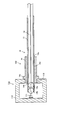
- FIG. 1A is a side view of the optical coupling member according to the first embodiment
- FIG. 1B is a cross-sectional view of the optical coupling member according to the first embodiment
- FIG. 1C is a two-dot chain line shown in FIG. It is an enlarged view in B.
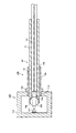
- FIG. 3A is a side view of the optical coupling member according to the second embodiment
- FIG. 3B is a cross-sectional view of the optical coupling member according to the second embodiment
- FIG. 3C is a two-dot chain line shown in FIG. 3B. It is an enlarged view in B.
- It is a cross-sectional schematic diagram which shows the state which connected the optical connector which concerns on 2nd Embodiment to an optical device. It is sectional drawing of the accommodating part vicinity in the optical coupling member which concerns on 3rd Embodiment.
- FIG. 1A is a side view of an optical coupling member 10 according to a first embodiment of the present invention
- FIG. 1B is a cross-sectional view of the optical coupling member 10.
- the light coupling member 10 has a holder 11 as a holding member having a generally cylindrical shape, a ball lens group 12 held by one end of the holder 11, and the other end of the holder 11.
- the ball lens group 12 is composed of a ball lens 12a as a first ball lens and a ball lens 12b as a second ball lens.
- the holder 11 is formed, for example, by molding a metal material, a resin material, or a ceramic material.
- a metal material which comprises holder 11, stainless steel, a copper system material, etc. can be used, for example.
- a resin material constituting the holder 11 for example, polypropylene (PP), acrylonitrile-butadiene-styrene copolymer (ABS), polyacetal (POM), polycarbonate (PC), polybutylene terephthalate (PBT), polyethylene terephthalate (PET) And polyethylene naphthalate (PEN), polyether sulfone (PES), polyphenylene ether (PPE), polyamidoimide (PAI), and polyether imide (PEI).
- the holder 11 is formed by subjecting these resin materials to various molding such as injection molding, extrusion molding or press molding.
- a ceramic material which comprises the holder 11 a zirconia, an alumina, a silicon nitride, silicon carbide etc. can be used, for example.
- the holder 11 is formed by subjecting these ceramic materials to various moldings such as injection molding, extrusion molding, or press molding.
- a material which comprises the holder 11 glass, crystallized glass, etc. can also be used.
- an opening 11 b is provided at an end of the holder 11 on the ball lens group 12 side.
- a housing 11c for housing the ball lens group 12 is provided inside the opening 11b.
- the housing portion 11c is provided in a size slightly smaller than the diameter of the ball lenses 12a and 12b constituting the ball lens group 12, and the ball lenses 12a and 12b can be press-fitted.
- a through hole 11d having substantially the same diameter as the outer diameter of the optical fiber 13 is provided in the inside of the holder 11.
- the through hole 11 d is provided so as to be connected to the insertion hole 11 a and to be connected to the housing portion 11 c.
- the ball lenses 12a and 12b constituting the ball lens group 12 are formed, for example, by molding a glass material.
- the ball lens 12a and the ball lens 12b according to the first embodiment are configured to have approximately the same diameter.
- the ball lens 12a and the ball lens 12b are housed in the housing portion 11c in a state of being in contact with each other.
- the ball lens 12a is disposed such that a portion thereof is in contact with the tip of the optical fiber 13 inserted into the through hole 11d.
- the ball lens 12b is disposed so that a part thereof is exposed from the opening 11b, but may not be exposed.
- the optical fiber 13 can be used without limitation with conventionally known glass optical fiber, plastic optical fiber and H-PCF.
- a plastic optical fiber it is composed of a core 13a provided through the center thereof and a cladding 13b covering the periphery of the core 13a.
- the core 13a and the clad 13b are disposed on the same plane. That is, at the end face of the optical fiber 13 in contact with the ball lens 12a, the core 13a and the clad 13b are arranged in line.
- the optical fiber 13 is inserted into the through hole 11d through the insertion hole 11a, and is fixed in a state in which the tip end portion of the optical fiber 13 is in contact with the ball lens 12a.
- the optical fiber 13 is fixed to the holder 11 by, for example, an adhesive applied between the optical fiber 13 and the inner circumferential surface of the through hole 11 d.
- the fixing of the optical fiber 13 to the holder 11 is not limited to this, and any fixing method can be applied.
- FIG. 1C is an enlarged view within the dashed-two dotted line B shown in FIG. 1B.
- a step 11e is formed at the boundary between a portion slightly smaller than the diameter of the ball lenses 12a and 12b and a portion substantially the same diameter as the outer diameter of the optical fiber 13. Is formed.
- the outer diameter of the optical fiber 13 is smaller than the diameters of the ball lenses 12a and 12b, so the ball lens 12a press-fitted through the opening 11b is stopped when a part thereof contacts the step 11e. , Is positioned at a predetermined position.
- the ball lens 12 b When a part of the ball lens 12 b pressed in from the opening 11 b contacts the ball lens 12 a, the ball lens 12 b is stopped and positioned at a predetermined position. Further, the optical fiber 13 inserted from the insertion hole 11a stops when the tip end portion contacts the ball lens 12a, and is positioned at a predetermined position. Thus, the ball lens group 12 and the optical fiber 13 are respectively positioned at predetermined positions of the holder 11 in a state where the ball lens 12 a is in contact with the ball lens 12 b and the optical fiber 13.
- the assembling step of the optical coupling member 10 includes a step (a) of pressing the ball lens 12a into the holder 11, a step (b) of pressing the ball lens 12b into the holder 11, and a step of inserting the optical fiber 13 (c). And). Each step will be described in detail below.
- the ball lens 12a is press-fit into the housing portion 11c from the opening 11b of the holder 11.
- the pressed-in ball lens 12a stops when a portion thereof contacts the step portion 11e.
- the press-fitting operation is completed.
- the orientation adjustment at the time of press-fitting into the holder 11 is unnecessary and the assembly is easy.
- the ball lens 12 a is in contact with the inner wall defining the housing portion 11 c in the holder 11. Since the housing portion 11c is provided in a size slightly smaller than the diameter of the ball lenses 12a and 12b constituting the ball lens group 12, the ball lens 12a is subjected to pressure exerted by the inner wall defining the housing portion 11c. It is fixed. Thus, the ball lens 12a is positioned and fixed at a predetermined position.
- the ball lens 12 b is press-fit into the housing portion 11 c from the opening 11 b of the holder 11.
- the pressed-in ball lens 12b is stopped when a part thereof contacts the ball lens 12a.
- the press-fitting operation is completed.
- the orientation adjustment at the time of press-fitting into the holder 11 is unnecessary and the assembly is easy.
- the central axis of the ball lens 12b is in a state of being aligned with the central axis of the ball lens 12a.
- the ball lens 12 b contacts an inner wall defining the housing portion 11 c in the holder 11. Since the housing portion 11c is provided in a size slightly smaller than the diameter of the ball lenses 12a and 12b constituting the ball lens group 12, the ball lens 12b is subjected to pressure from the inner wall defining the housing portion 11c. It is fixed. Thus, the ball lens 12b is positioned and fixed at a predetermined position.
- the optical fiber 13 is inserted into the through hole 11 d from the insertion hole 11 a of the holder 11.
- the optical fiber 13 is guided by the inner wall defining the through hole 11 d to reach the ball lens 12 a.
- the insertion operation is finished.
- the optical fiber 13 is positioned at a predetermined position.
- the central axis of the optical fiber 13 is aligned with the central axes of the ball lenses 12 a and 12 b constituting the ball lens group 12.
- axial alignment of the optical fiber 13 and the ball lens group 12 can be easily performed.
- the ball lens 12a is fixed by the pressure by the holder 11 and further sandwiched between the step portion 11e and the fixed ball lens 12b, the position does not shift even when the optical fiber 13 is hit.
- the optical coupling member 10 shown in FIG. 1 can be assembled.
- the ball lens 12a is in contact with the ball lens 12b and the optical fiber 13
- the ball lens 12b and the light are referred to with reference to the ball lens 12a. Since the fiber 13 can be positioned, working efficiency can be improved, and the ball lens group 12 and the optical fiber 13 can be easily positioned. Therefore, it is possible to align the ball lens group 12 and the optical fiber 13 with high accuracy while relaxing the accuracy of the assembly operation.
- the lens periphery of the light coupling member 10 can be made compact.
- the ball lens 12 a functions as a spacer for aligning the ball lens 12 b with the optical fiber 13.
- the holder 11 does not require a complicated structure, and the increase in the cost of the entire optical coupling member 10 can be suppressed. .
- FIG. 2 is a schematic cross-sectional view showing a state in which the optical connector 100 according to the present embodiment is connected to the optical device 110.
- the optical device 110 provided with light reception / light emitting element is demonstrated for convenience of explanation, the structure of the optical device 110 is not limited to this, It can change suitably.
- the optical connector 100 is configured by attaching the resin coupling 14 to the optical coupling member 10.
- the optical device 110 is configured by arranging the light receiving / emitting element 111 inside the case 112. Further, an opening 113 for inserting the optical connector 100 is provided on the side surface of the case 112 in the optical device 110.
- the resin joint 14 has a generally cylindrical shape, and one end thereof is provided with an insertion hole 14a into which the holder 11 is inserted, and the other end is provided with an opening 14b from which the holder 11 protrudes.
- the through hole 14 c continuing from the insertion hole 14 a to the opening 14 b is provided to have substantially the same diameter as the outer diameter of the holder 11. Further, on the outer peripheral surface in the vicinity of the opening 14 b, an annular collar-like portion 14 d is provided.
- the holder 11 is inserted into the through hole 14c through the insertion hole 14a of the resin joint 14, and is fixed in a state in which the tip portion thereof protrudes from the opening 14b.
- the holder 11 is fixed, for example, by a plurality of fixing portions provided on the same circumference in the vicinity of the flange portion 14 d of the resin joint 14. These fixing portions are formed by inserting the holder 11 so as to be positioned at a predetermined position of the resin joint 14 and then performing pressing from the outside of the resin joint 14 using a tool.
- the outer diameter of the collar portion 14 d is larger than the inner diameter of the opening 113 in the optical device 110 to which the optical connector 100 is connected. Therefore, when the optical connector 100 is inserted into the optical device 110, up to the hooked portion 14d is always inserted into the optical device 110, and the optical connector 100 can be positioned at a predetermined position in the case 112. It becomes possible.
- the optical device 110 In the optical device 110, light emitted from the light receiving / emitting element 111 travels in the ball lens 12 b and is collected at the end of the fiber 13. The light thus incident propagates in the optical fiber 13.
- the optical device 110 In the optical device 110, light emitted from the optical fiber 13 travels in the ball lens 12a and then travels in the ball lens 12b. A beam emitted from the ball lens 12 b is condensed on the light receiving / emitting element 111 placed at a position to be condensed by the ball lens 12 b.
- the optical device 110 when the optical connector 100 is inserted to a predetermined position in the case 112, light propagating between the light receiving / emitting element 111 and the optical fiber 13 passes through the ball lens group 12. Are designed to be able to enter and exit properly.
- the assembly accuracy required for axis alignment can be relaxed.
- the light coupling member 20 having a structure different from that of the light coupling member 10 shown in the first embodiment will be described.
- the light coupling member 20 uses two ball lenses having different diameters as a ball lens 22a as a first ball lens and a ball lens 22b as a second ball lens constituting the ball lens group 22, and
- the configuration of the holder 21 accommodating the ball lens group 22 is different from the light coupling member 10 according to the first embodiment.
- FIG. 3A is a side view of the optical coupling member 20 according to the second embodiment of the present invention
- FIG. 3B is a cross-sectional view of the optical coupling member 20
- FIG. 3C is a two-dot chain line shown in FIG. It is an enlarged view in B.
- the same components as those of the optical coupling member 10 according to the first embodiment are designated by the same reference numerals, and the description thereof is omitted.
- the ball lenses 22a and 22b constituting the ball lens group 22 are formed, for example, by molding a glass material. As shown in FIGS. 3B and 3C, in the ball lenses 22a and 22b, the ball lens 22a is smaller in diameter than the ball lens 22b. The diameter of the ball lens 22a can be set to any size in accordance with the set distance between the ball lens 22b and the end face of the optical fiber 13.
- the holder 21 differs from the holder 11 according to the first embodiment in that the holder 21 has a housing portion 21a for housing the ball lenses 22a and 22b.
- the housing portion 21a is provided with a portion slightly smaller than the diameter of the ball lens 22a and a portion slightly smaller than the diameter of the ball lens 22b.
- a stepped portion 21 b is formed at the boundary between a portion slightly smaller than the diameter of the ball lens 22 a and a portion substantially the same diameter as the outer diameter of the optical fiber 13.
- a stepped portion 21c is formed at the boundary between a portion slightly smaller than the diameter of the ball lens 22b and a portion slightly smaller than the diameter of the ball lens 22a.
- the ball lens 22a pressed in through the opening 11b is stopped when a part thereof contacts the step 21b, and is positioned at a predetermined position. Further, the ball lens 22b press-fitted through the opening 11b is positioned at a predetermined position by partially contacting the ball lens 22a.
- the optical fiber 13 inserted from the insertion hole 11a is stopped when its tip end contacts the ball lens 22a, and is positioned at a predetermined position.
- the ball lens group 22 and the optical fiber 13 are respectively positioned at predetermined positions of the holder 21 in a state where the ball lens 22a is in contact with the ball lens 22b and the optical fiber 13.
- the assembling step of the optical coupling member 20 includes a step (d) of pressing the ball lens 22a into the holder 21, a step (e) of pressing the ball lens 22b into the holder 21, and a step of inserting the optical fiber 13 (f) And). Each step will be described in detail below.
- the ball lens 22a is press-fit into the housing portion 21a from the opening 11b of the holder 21.
- the pressed-in ball lens 22a stops when a portion thereof contacts the step 21b.
- the press-fitting operation is completed.
- the optical coupling member 20 since the ball lens 22a having no directivity is used as the lens, the orientation adjustment at the time of press-fitting into the holder 21 is unnecessary, and the assembly is easy.
- the ball lens 22 a is in contact with the inner wall that defines the housing portion 21 a in the holder 21.
- the step 21b to the step 21c are provided in a size slightly smaller than the diameter of the ball lens 22a, so the ball lens 22a works under pressure by the inner wall defining the housing 21a. Fixed by Thus, the ball lens 22a is positioned and fixed at a predetermined position.
- the ball lens 22 b is press-fit into the housing portion 21 a from the opening 11 b of the holder 21.
- the pressed-in ball lens 22b is stopped when a part thereof contacts the ball lens 22a.
- the press-fitting operation is completed.
- the optical coupling member 20 since the ball lens 22b having no directivity is used as a lens, the adjustment of the orientation when pressing into the holder 21 is unnecessary, and the assembly is easy. Further, by press-fitting into the housing portion 21 a of the holder 21, the central axis of the ball lens 22 b is in a state of coinciding with the central axis of the ball lens 22 a.
- the ball lens 22 b is in contact with the inner wall that defines the housing portion 21 a in the holder 21.
- the step 21c to the opening 11b are provided in a size slightly smaller than the diameter of the ball lens 22b, so the ball lens 22b works under pressure by the inner wall defining the housing portion 21a. Fixed by Thus, the ball lens 22b is positioned and fixed at a predetermined position.
- the optical fiber 13 is inserted into the through hole 11 d from the insertion hole 11 a of the holder 21.
- the optical fiber 13 is guided by the inner wall defining the through hole 11 d to reach the ball lens 22 a.
- the insertion operation is finished.
- the optical fiber 13 is positioned at a predetermined position.
- the central axis of the optical fiber 13 is aligned with the central axes of the ball lenses 22 a and 22 b constituting the ball lens group 22.
- axial alignment of the optical fiber 13 and the ball lens group 22 can be easily performed.
- the ball lens 22a is fixed by the pressure of the holder 21 and further sandwiched between the step 21b and the fixed ball lens 22b, so that the position does not shift even when the optical fiber 13 is hit.
- the ball lens 22a is in contact with the ball lens 22b and the optical fiber 13
- the ball lens 22b and the light are referenced based on the ball lens 22a. Since the fiber 13 can be positioned, working efficiency can be improved, and the ball lens group 22 and the optical fiber 13 can be easily positioned. Therefore, it is possible to align the ball lens group 22 and the optical fiber 13 with high accuracy while reducing the assembly accuracy.
- FIG. 4 is a schematic cross-sectional view showing a state in which the optical connector 120 according to the present embodiment is connected to the optical device 110.
- the optical connector 120 according to the present embodiment is configured by attaching the resin coupling 14 to the optical coupling member 20.
- the configuration of the optical device 110 is not limited to this, and can be changed as appropriate.
- the optical device 110 In the optical device 110, light emitted from the light receiving / emitting element 111 travels in the ball lens 22 b and is condensed at the end of the optical fiber 13. The light thus incident propagates in the optical fiber 13.
- the optical device 110 In the optical device 110, light emitted from the optical fiber 13 travels in the ball lens 12a and then travels in the ball lens 22b. A beam emitted from the ball lens 22 b is condensed on the light receiving / emitting element 111 placed at a position to be condensed by the ball lens 22 b.
- the diameter of the ball lens in contact with the optical fiber 13 of the optical connector 120 is smaller. Therefore, it is possible to control the state of the beam by the diameter of the ball lens 22a in contact with the optical fiber 13.
- the optical device 110 when the optical connector 100 is inserted to a predetermined position in the case 112, light propagating between the light receiving / emitting element 111 and the optical fiber 13 passes through the ball lens group 22.
- the ball lens group 22 are designed to be able to enter and exit properly.
- the assembly accuracy required for axis alignment can be relaxed.
- the light coupling member 30 having a structure different from that of the light coupling member 20 shown in the second embodiment will be described.
- the light coupling member 30 differs from the light coupling member 20 in that the refractive index matching agent 23 is filled around the ball lens group 22 in the housing portion 21a.
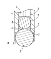
- FIG. 5 is a cross-sectional view of the vicinity of the housing portion 21 a in the light coupling member 30.
- the same components as those of the light coupling member 20 according to the second embodiment are designated by the same reference numerals, and the description thereof is omitted.
- a refractive index matching agent 23 is filled around the contact point of the ball lens 22b and the ball lens 22a and around the contact surface of the ball lens 22a and the optical fiber 13.
- the refractive index matching agent 23 is made of, for example, a known material in which a glass filler is mixed with a base material of silicone diameter.
- the refractive index matching agent 23 for example, press-fits a part of the ball lens 22 b coated with the refractive index matching agent 23 into the housing portion 21 a, and applies the refractive index matching agent 23 to the tip of the optical fiber 13. By inserting the above into the through hole 11d, the inside of the housing portion 21a can be filled.
- the refractive index matching agent 23 is filled around the contact point between the ball lens 22b and the ball lens 22a and around the contact surface between the ball lens 22a and the optical fiber 13. Since it is possible to adjust the refractive index from the optical fiber 13 to the ball lens 22b via the ball lens 22a and to reduce the reflection during propagation, it is possible to suppress the amount of attenuation of the propagating light. Moreover, it becomes possible to collimate the emitted light from the ball lens 22b.
- the holders 11 and 21 have a generally cylindrical shape, but the configuration of the holders 11 and 21 is not limited to this. Appropriate changes are possible.
- the holders 11 and 21 while the accommodation portions 11c and 21a for accommodating the ball lens groups 12 and 22 are formed at one end, it is arbitrary on the premise that the insertion hole 11a of the optical fiber 13 is formed at the other end.
- the shape of can be adopted. For example, those having a rectangular tube shape (i.e., a cylindrical body having a square cross section orthogonal to the insertion direction of the optical fiber 13) are included.
- the ball lens groups 12 and 22 are formed by two ball lenses
- the configuration of the ball lens groups is limited to this. It is possible to make changes as appropriate.
- the ball lens group may be configured by three or more ball lenses.
- the assembling process of the optical coupling member 10 is described in the order of the steps (a) to (c), but the assembling process is not limited to this and can be appropriately modified. It is.
- the optical coupling member 10 may be assembled in the order of steps (a), (c) and (b).
- the assembly process of the optical coupling member 20 has been described in the order of steps (d) to (f), but, for example, in the steps (d), (f) and (e) You may make it assemble in order.
- the optical coupling member 30 is configured such that the refractive index matching agent 23 is filled around the ball lens group 22 in the housing 21a to accommodate the optical coupling member 20 according to the second embodiment.
- the configuration of the light coupling member 30 is not limited to this, and can be changed as appropriate.
- the optical coupling member 30 may be configured such that the refractive index matching agent 23 is filled around the ball lens group 12 in the housing portion 11c of the optical coupling member 10 according to the first embodiment.
Landscapes
- Physics & Mathematics (AREA)
- General Physics & Mathematics (AREA)
- Optics & Photonics (AREA)
- Optical Couplings Of Light Guides (AREA)
Abstract
Description
以下、本発明の実施の形態について添付図面を参照して詳細に説明する。
図1Aは、本発明の第1の実施の形態に係る光結合部材10の側面図であり、図1Bは、光結合部材10の断面図である。図1A,Bに示すように、光結合部材10は、概して円筒形状を有する保持部材としてのホルダ11と、このホルダ11の一端部に保持されるボールレンズ群12と、ホルダ11の他端部に設けられた挿入孔11aから挿入される光ファイバ13と、を含んで構成される。光結合部材10において、ボールレンズ群12は、第1のボールレンズとしてのボールレンズ12aと、第2のボールレンズとしてのボールレンズ12bとで構成される。
まず、ホルダ11の開口部11bから、ボールレンズ12aを収容部11c内に圧入する。圧入されたボールレンズ12aは、その一部が段差部11eに接すると停止する。ボールレンズ12aが段差部11eに接したところで、圧入作業は終了する。光結合部材10においては、レンズとして方向性がないボールレンズ12aを使うため、ホルダ11に圧入する際の方位調整が不要であり組み立てし易い。
次に、ホルダ11の開口部11bから、ボールレンズ12bを収容部11c内に圧入する。圧入されたボールレンズ12bは、その一部がボールレンズ12aに接すると停止する。ボールレンズ12bがボールレンズ12aに接したところで、圧入作業は終了する。光結合部材10においては、レンズとして方向性がないボールレンズ12bを使うため、ホルダ11に圧入する際の方位調整が不要であり組み立てし易い。また、ホルダ11の収容部11c内に圧入することにより、ボールレンズ12bの中心軸は、ボールレンズ12aの中心軸と一致した状態となる。
次に、ホルダ11の挿入孔11aから、光ファイバ13を貫通孔11d内に挿入する。光ファイバ13は、貫通孔11dを規定する内壁に案内されてボールレンズ12aに至る。光ファイバ13が、ボールレンズ12aに突き当たったところで、挿入作業は終了する。このとき、光ファイバ13は、所定の位置に位置決めされた状態となる。また、ホルダ11の貫通孔11dに挿入することにより、光ファイバ13の中心軸は、ボールレンズ群12を構成するボールレンズ12a,12bの中心軸と一致した状態となる。このように、光ファイバ13とボールレンズ群12との軸合わせを容易に行うことができる。
第1の実施の形態で示した光結合部材10とは異なる構造の光結合部材20について説明する。光結合部材20は、ボールレンズ群22を構成する第1のボールレンズとしてのボールレンズ22aおよび第2のボールレンズとしてのボールレンズ22bとして径の異なる2つのボールレンズを用いる点、ならびに、これらのボールレンズ群22を収容するホルダ21の構成において、第1の実施の形態に係る光結合部材10と相違する。
まず、ホルダ21の開口部11bから、ボールレンズ22aを収容部21a内に圧入する。圧入されたボールレンズ22aは、その一部が段差部21bに接すると停止する。ボールレンズ22aが段差部21bに接したところで、圧入作業は終了する。光結合部材20においては、レンズとして方向性がないボールレンズ22aを使うため、ホルダ21に圧入する際の方位調整が不要であり組み立てし易い。
次に、ホルダ21の開口部11bから、ボールレンズ22bを収容部21a内に圧入する。圧入されたボールレンズ22bは、その一部がボールレンズ22aに接すると停止する。ボールレンズ22bがボールレンズ22aに接したところで、圧入作業は終了する。光結合部材20においては、レンズとして方向性がないボールレンズ22bを使うため、ホルダ21に圧入する際の方位調整が不要であり組み立てし易い。また、ホルダ21の収容部21a内に圧入することにより、ボールレンズ22bの中心軸は、ボールレンズ22aの中心軸と一致した状態となる。
次に、ホルダ21の挿入孔11aから、光ファイバ13を貫通孔11d内に挿入する。光ファイバ13は、貫通孔11dを規定する内壁に案内されてボールレンズ22aに至る。光ファイバ13が、ボールレンズ22aに突き当たったところで、挿入作業は終了する。このとき、光ファイバ13は、所定の位置に位置決めされた状態となる。また、ホルダ21の貫通孔11dに挿入することにより、光ファイバ13の中心軸は、ボールレンズ群22を構成するボールレンズ22a,22bの中心軸と一致した状態となる。このように、光ファイバ13とボールレンズ群22との軸合わせを容易に行うことができる。
第2の実施の形態で示した光結合部材20とは異なる構造の光結合部材30について説明する。光結合部材30は、収容部21aにおけるボールレンズ群22の周囲に屈折率整合剤23を充填した点で、光結合部材20と相違する。
Claims (6)
- 光ファイバと、一端に形成された挿入孔から挿入された前記光ファイバを保持する保持部材と、前記保持部材の他端に形成された収容部に光軸方向に沿って収容される複数のボールレンズと、を具備し、前記複数のボールレンズは接した状態で配置されるとともに、前記光ファイバは対向するボールレンズに接した状態で配置されることを特徴とする光結合部材。
- 前記複数のボールレンズは、第1のボールレンズおよび第2のボールレンズで構成されており、前記挿入孔側から順に前記光ファイバ、前記第1のボールレンズ、前記第2のボールレンズが配置されることを特徴とする請求項1記載の光結合部材。
- 前記第1のボールレンズおよび前記第2のボールレンズは、同径であることを特徴とする請求項2記載の光結合部材。
- 前記第1のボールレンズは、前記第2のボールレンズより小径であることを特徴とする請求項2記載の光結合部材。
- 前記複数のボールレンズの周囲には、屈折率整合剤が充填されていることを特徴とする請求項1記載の光結合部材。
- 請求項1記載の光結合部材を接続することを特徴とする光コネクタ。
Priority Applications (4)
| Application Number | Priority Date | Filing Date | Title |
|---|---|---|---|
| KR1020147021598A KR20140119083A (ko) | 2012-01-27 | 2012-10-16 | 광 결합 부재 및 광 커넥터 |
| CN201280068187.8A CN104094144A (zh) | 2012-01-27 | 2012-10-16 | 光耦合构件及光连接器 |
| US14/371,695 US20140376860A1 (en) | 2012-01-27 | 2012-10-16 | Optical coupling member and optical connector |
| EP12866702.9A EP2808714A4 (en) | 2012-01-27 | 2012-10-16 | OPTICAL COUPLING AND OPTICAL CONNECTOR |
Applications Claiming Priority (2)
| Application Number | Priority Date | Filing Date | Title |
|---|---|---|---|
| JP2012015281A JP2013156337A (ja) | 2012-01-27 | 2012-01-27 | 光結合部材および光コネクタ |
| JP2012-015281 | 2012-01-27 |
Publications (1)
| Publication Number | Publication Date |
|---|---|
| WO2013111398A1 true WO2013111398A1 (ja) | 2013-08-01 |
Family
ID=48873144
Family Applications (1)
| Application Number | Title | Priority Date | Filing Date |
|---|---|---|---|
| PCT/JP2012/076653 Ceased WO2013111398A1 (ja) | 2012-01-27 | 2012-10-16 | 光結合部材および光コネクタ |
Country Status (7)
| Country | Link |
|---|---|
| US (1) | US20140376860A1 (ja) |
| EP (1) | EP2808714A4 (ja) |
| JP (1) | JP2013156337A (ja) |
| KR (1) | KR20140119083A (ja) |
| CN (1) | CN104094144A (ja) |
| TW (1) | TW201331651A (ja) |
| WO (1) | WO2013111398A1 (ja) |
Families Citing this family (6)
| Publication number | Priority date | Publication date | Assignee | Title |
|---|---|---|---|---|
| WO2016170838A1 (ja) * | 2015-04-23 | 2016-10-27 | オリンパス株式会社 | 内視鏡システム |
| US9941965B2 (en) * | 2015-07-15 | 2018-04-10 | Flextronics Ap, Llc | Laser and optical charging and communications device and method of use |
| WO2018229992A1 (ja) * | 2017-06-16 | 2018-12-20 | 京セラ株式会社 | 光コネクタモジュール |
| US11467351B2 (en) | 2019-12-27 | 2022-10-11 | Panduit Corp. | Expanded beam connector |
| CN113050227A (zh) * | 2021-03-12 | 2021-06-29 | 深圳市启翔光电技术有限公司 | 一种光纤准直器 |
| JP2024059490A (ja) * | 2022-10-18 | 2024-05-01 | 株式会社タムロン | 信号光伝達部材 |
Citations (4)
| Publication number | Priority date | Publication date | Assignee | Title |
|---|---|---|---|---|
| JPS57155513U (ja) * | 1981-03-24 | 1982-09-30 | ||
| JPS62141509A (ja) * | 1985-12-16 | 1987-06-25 | ポラロイド コ−ポレ−シヨン | 光フアイバ・コネクタ |
| JPS63194210A (ja) * | 1987-02-06 | 1988-08-11 | Hamai Denkyu Kogyo Kk | 光フアイバ−用接触型ボ−ルレンズランプ |
| JPH01128013A (ja) | 1987-11-13 | 1989-05-19 | Hitachi Ltd | 光モジュール用ファイバコリメータ |
Family Cites Families (11)
| Publication number | Priority date | Publication date | Assignee | Title |
|---|---|---|---|---|
| JP2836583B2 (ja) * | 1996-05-31 | 1998-12-14 | 日本電気株式会社 | 受光素子と光ファイバの光学的結合構造 |
| US5940564A (en) * | 1997-08-05 | 1999-08-17 | Picolight, Inc. | Device for coupling a light source or receiver to an optical waveguide |
| JP2004118223A (ja) * | 2000-03-22 | 2004-04-15 | Matsushita Electric Ind Co Ltd | 光学デバイス、光通信部品および光伝送装置 |
| CN1571935A (zh) * | 2001-10-19 | 2005-01-26 | 奥普蒂莱恩股份公司 | 光学子组件 |
| JP2007241094A (ja) * | 2006-03-10 | 2007-09-20 | Tyco Electronics Amp Kk | 光ファイバコリメータ |
| EP1884809B1 (en) * | 2006-07-31 | 2018-02-14 | TE Connectivity Corporation | Expanded beam connector |
| EP1903361B1 (en) * | 2006-09-22 | 2020-04-01 | Nippon Electric Glass Co., Ltd. | Optical component and light emitting device using the same |
| US7775725B2 (en) * | 2008-10-29 | 2010-08-17 | Tyco Electronics Corporation | Single-channel expanded beam connector |
| JP4866961B2 (ja) * | 2010-04-16 | 2012-02-01 | 三菱鉛筆株式会社 | 光コリメータ及びこれを用いた光コネクタ、並びに、光コリメータ用保持部材 |
| US8827567B2 (en) * | 2011-08-10 | 2014-09-09 | Tyco Electronics Corporation | Field-installable expanded beam connector system |
| US9588302B2 (en) * | 2012-06-01 | 2017-03-07 | Te Connectivity Corporation | Expanded-beam connector with molded lens |
-
2012
- 2012-01-27 JP JP2012015281A patent/JP2013156337A/ja active Pending
- 2012-10-16 CN CN201280068187.8A patent/CN104094144A/zh active Pending
- 2012-10-16 EP EP12866702.9A patent/EP2808714A4/en not_active Withdrawn
- 2012-10-16 WO PCT/JP2012/076653 patent/WO2013111398A1/ja not_active Ceased
- 2012-10-16 KR KR1020147021598A patent/KR20140119083A/ko not_active Ceased
- 2012-10-16 US US14/371,695 patent/US20140376860A1/en not_active Abandoned
- 2012-10-31 TW TW101140409A patent/TW201331651A/zh unknown
Patent Citations (4)
| Publication number | Priority date | Publication date | Assignee | Title |
|---|---|---|---|---|
| JPS57155513U (ja) * | 1981-03-24 | 1982-09-30 | ||
| JPS62141509A (ja) * | 1985-12-16 | 1987-06-25 | ポラロイド コ−ポレ−シヨン | 光フアイバ・コネクタ |
| JPS63194210A (ja) * | 1987-02-06 | 1988-08-11 | Hamai Denkyu Kogyo Kk | 光フアイバ−用接触型ボ−ルレンズランプ |
| JPH01128013A (ja) | 1987-11-13 | 1989-05-19 | Hitachi Ltd | 光モジュール用ファイバコリメータ |
Non-Patent Citations (1)
| Title |
|---|
| See also references of EP2808714A4 |
Also Published As
| Publication number | Publication date |
|---|---|
| TW201331651A (zh) | 2013-08-01 |
| US20140376860A1 (en) | 2014-12-25 |
| EP2808714A1 (en) | 2014-12-03 |
| CN104094144A (zh) | 2014-10-08 |
| EP2808714A4 (en) | 2015-11-25 |
| JP2013156337A (ja) | 2013-08-15 |
| KR20140119083A (ko) | 2014-10-08 |
Similar Documents
| Publication | Publication Date | Title |
|---|---|---|
| WO2013111398A1 (ja) | 光結合部材および光コネクタ | |
| US6862384B2 (en) | Light source-optical fiber coupler | |
| CN107111069A (zh) | 插座连接器及光耦合构造 | |
| US12306446B2 (en) | Ferrule and optical connector | |
| EP3133427B1 (en) | Expanded beam connector with discrete alignment assembly | |
| US9195016B2 (en) | Optical connector | |
| JP2006220717A (ja) | 光ファイバ接続部品およびこれを使用した光ファイバ接続器 | |
| US8967880B2 (en) | Optical collimator and optical connector using same | |
| US20140334784A1 (en) | Optical connector | |
| JP5543293B2 (ja) | 小径曲げ光コネクタ | |
| US11714242B2 (en) | Optical fiber array and optical fiber connection structure | |
| US20120020626A1 (en) | Optical Fiber Connector | |
| JP2013160868A (ja) | 光結合部材およびこれを用いた光コネクタならびに光結合部材の製造方法 | |
| JP2015175979A (ja) | 光ファイバコネクタ | |
| JP2006126535A (ja) | 光軸合わせ構造 | |
| JP5743676B2 (ja) | 光コネクタ | |
| JP5657944B2 (ja) | レンズ付き光コネクタ | |
| JP2014038303A (ja) | 光コネクタ、及び嵌合ユニット | |
| CN1312864C (zh) | 光纤连接装置 | |
| JP2015001570A (ja) | 光接続装置 | |
| JP3874405B2 (ja) | 光フェルール用レセプタクルの組立方法 | |
| JP2014026153A (ja) | 光結合部材およびこれを用いた光コネクタ | |
| WO2013065607A1 (ja) | 光学デバイス | |
| JP2011197018A (ja) | 光学素子モジュール | |
| JP2012198429A (ja) | 多心式光ファイバホルダとホルダ本体部 |
Legal Events
| Date | Code | Title | Description |
|---|---|---|---|
| 121 | Ep: the epo has been informed by wipo that ep was designated in this application |
Ref document number: 12866702 Country of ref document: EP Kind code of ref document: A1 |
|
| WWE | Wipo information: entry into national phase |
Ref document number: 14371695 Country of ref document: US |
|
| REEP | Request for entry into the european phase |
Ref document number: 2012866702 Country of ref document: EP |
|
| WWE | Wipo information: entry into national phase |
Ref document number: 2012866702 Country of ref document: EP |
|
| NENP | Non-entry into the national phase |
Ref country code: DE |
|
| ENP | Entry into the national phase |
Ref document number: 20147021598 Country of ref document: KR Kind code of ref document: A |