WO2013111527A1 - 流量計測装置 - Google Patents
流量計測装置 Download PDFInfo
- Publication number
- WO2013111527A1 WO2013111527A1 PCT/JP2013/000100 JP2013000100W WO2013111527A1 WO 2013111527 A1 WO2013111527 A1 WO 2013111527A1 JP 2013000100 W JP2013000100 W JP 2013000100W WO 2013111527 A1 WO2013111527 A1 WO 2013111527A1
- Authority
- WO
- WIPO (PCT)
- Prior art keywords
- measurement
- flow rate
- unit
- flow
- ultrasonic
- Prior art date
- Legal status (The legal status is an assumption and is not a legal conclusion. Google has not performed a legal analysis and makes no representation as to the accuracy of the status listed.)
- Ceased
Links
Images


Classifications
-
- G—PHYSICS
- G01—MEASURING; TESTING
- G01F—MEASURING VOLUME, VOLUME FLOW, MASS FLOW OR LIQUID LEVEL; METERING BY VOLUME
- G01F1/00—Measuring the volume flow or mass flow of fluid or fluent solid material wherein the fluid passes through a meter in a continuous flow
- G01F1/66—Measuring the volume flow or mass flow of fluid or fluent solid material wherein the fluid passes through a meter in a continuous flow by measuring frequency, phase shift or propagation time of electromagnetic or other waves, e.g. using ultrasonic flowmeters
- G01F1/662—Constructional details
-
- G—PHYSICS
- G01—MEASURING; TESTING
- G01F—MEASURING VOLUME, VOLUME FLOW, MASS FLOW OR LIQUID LEVEL; METERING BY VOLUME
- G01F1/00—Measuring the volume flow or mass flow of fluid or fluent solid material wherein the fluid passes through a meter in a continuous flow
- G01F1/72—Devices for measuring pulsing fluid flows
-
- G—PHYSICS
- G01—MEASURING; TESTING
- G01F—MEASURING VOLUME, VOLUME FLOW, MASS FLOW OR LIQUID LEVEL; METERING BY VOLUME
- G01F1/00—Measuring the volume flow or mass flow of fluid or fluent solid material wherein the fluid passes through a meter in a continuous flow
- G01F1/66—Measuring the volume flow or mass flow of fluid or fluent solid material wherein the fluid passes through a meter in a continuous flow by measuring frequency, phase shift or propagation time of electromagnetic or other waves, e.g. using ultrasonic flowmeters
- G01F1/667—Arrangements of transducers for ultrasonic flowmeters; Circuits for operating ultrasonic flowmeters
Definitions
- the present invention relates to a flow rate measuring apparatus that measures the flow rate of a fluid such as gas using ultrasonic waves, and in particular, performs flow rate measurement at each sampling period set as the minimum time unit for the flow rate measurement.
- the present invention relates to a flow rate measuring device.
- ultrasonic transducers are provided on the upstream side and the downstream side of a flow channel (measurement flow channel) to be subjected to flow rate measurement, and pulsed ultrasonic waves are alternately transmitted and received.
- the flow velocity of the fluid can be measured using the propagation time in each of the forward direction and the reverse direction, the flow rate of the fluid can be measured using the flow velocity and the cross-sectional area of the measurement channel.
- the flow rate measuring device using the reciprocal difference method of propagation time typically, there is an estimation type (or estimation type) gas meter.
- a guessing-type gas meter intermittently samples and measures the flow rate of a gas in a pipe serving as a measurement channel, calculates the average value of the measured values, and integrates them to calculate the gas usage (flow rate integrated value). It is configured to acquire.
- Sampling measurement is basically performed once for each preset sampling period. That is, the sampling period is a period set as the minimum time unit for flow rate measurement.
- the estimation type gas meter having the above-described configuration does not need to include a mechanical operation unit for measuring a flow rate as compared with a conventional real capacity type (actual measurement type) gas meter (for example, a membrane type gas meter). Therefore, since the number of parts can be reduced, the size and cost can be reduced.
- a conventional real capacity type (actual measurement type) gas meter for example, a membrane type gas meter
- gas is a compressible fluid, unlike liquid such as water
- pulsation is likely to occur in the gas flow in the process of passing through a gas compression device such as a gas engine heat pump (GHP).
- GTP gas engine heat pump
- the gas flow rate value when pulsation occurs periodically, if the pulsation period and the sampling period are the same or close to each other, or if the pulsation period is an integral multiple of the sampling period, only the peak value of the pulsation is used as the gas flow rate value. Or only the bottom value may be measured. In such a case, the error of the gas flow rate value is relatively large, and if the flow rate value including the error is further integrated, the gas usage amount that is the integrated value greatly deviates from the actual usage amount. It becomes a thing.
- Patent Literature 1 discloses a flow rate measurement method and a flow rate measurement device that change a start phase of a measurement period based on predetermined regularity. Specifically, a predetermined time interval Td is provided for each measurement period T, and the predetermined timing period or phase of the start timings of the plurality of measurement periods T is set to be different from the actually measured pulsation period or phase. It is changed based on regularity.
- the guessing type gas meter using the reciprocal propagation time method can measure the flow rate of gas in a few seconds by transmitting and receiving ultrasonic waves, and can acquire the measured flow rate value as digital data. It is possible to connect to various networks via a communication function or connect to other devices to configure a system.
- the estimation type gas meter can be provided with various security functions. In order to cope with such a use situation, a flow rate measurement with higher accuracy is being demanded for a guessing gas meter.
- the technique disclosed in Patent Document 1 has a configuration in which the start timing of the flow rate measurement (measurement period T) is shifted by the time interval Td in each sampling period. Therefore, in this configuration, for example, when a pulsation that occurs in a single shot or a pulsation with a period different from the assumption occurs, it may not be able to cope with it sufficiently. Therefore, it is necessary to further reduce the influence of pulsation in the usage situation assumed in the future.
- the present invention has been made to solve such a problem, and in a flow rate measuring device using a reciprocal difference in propagation time such as a guessing type gas meter, the influence of pulsation is further effectively reduced, and the flow rate measurement is performed.
- the purpose of this is to further improve the accuracy.
- the flow rate measuring device includes a pair of ultrasonic transmitters / receivers disposed so as to cross and face a measurement channel through which a fluid to be measured flows, and the ultrasonic transmitter / receiver
- the flow rate measurement unit that measures the flow rate of the fluid by transmitting and receiving ultrasonic waves between the flow rate measurement unit and the flow rate measurement unit at the sampling period that is set as the minimum time unit for the flow rate measurement.
- a measurement control unit that controls the flow rate measurement unit to divide the sampling period into three or more equally spaced measurement blocks and to the flow rate measurement unit for each measurement block.
- the flow rate measurement unit calculates the average value of the flow rate values obtained in all the measurement blocks as the flow rate value of the sampling cycle for each sampling cycle. It is so that configuration.
- the measurement control unit may control the flow measurement unit so that the flow measurement is performed at random timing for each measurement block.
- the flow measurement unit includes at least the pair of ultrasonic transmitters / receivers, a transmission / reception switching unit that switches transmission / reception of the ultrasonic transmitters / receivers, and the ultrasonic transmitter / receiver on the transmission side.
- An oscillation drive unit that is driven to transmit ultrasonic waves
- an ultrasonic detection unit that detects the ultrasonic waves received by the ultrasonic transceiver on the receiving side
- the pair of ultrasonic transceivers A propagation time measurement unit that measures the propagation time of the ultrasonic waves transmitted and received by and a flow rate calculation unit that calculates the flow rate value of the fluid from the propagation time.
- the flow rate calculation unit is stored in the measurement block flow rate calculation unit that calculates and stores a flow rate value for each measurement block, and the measurement block flow rate calculation unit for each sampling period.
- a sampling period flow rate calculation unit that calculates an average value of the flow rate values.
- the influence of pulsation can be further effectively reduced and the accuracy of flow rate measurement can be further improved in the flow rate measurement device using the reciprocal time difference method such as a guessing gas meter. , Has the effect.
- FIG. 1 is a block diagram showing a configuration of a flow rate measuring apparatus according to Embodiment 1 of the present invention.
- 2A is a time chart showing an example of the relationship between the sampling period and the configuration example of the measurement block and pulsation in the flow rate measuring apparatus shown in FIG. 1
- FIG. 2B shows the sampling period and pulsation in the conventional flow rate measuring apparatus. It is a time chart which shows a relationship.
- FIG. 3 is a time chart showing another example of the relationship between the sampling period and the configuration example of the measurement block and the pulsation in the flow rate measuring device shown in FIG.
- FIG. 4 is a block diagram showing the configuration of the flow rate measuring apparatus according to Embodiment 2 of the present invention.
- FIG. 5 is a time chart showing an example of the configuration of the sampling period and measurement block in the flow rate measuring apparatus shown in FIG.
- the configuration of the flow rate measuring apparatus according to Embodiment 1 of the present invention will be specifically described with reference to FIG.
- the flow rate measuring apparatus according to the present embodiment is an estimation type gas meter using the reciprocal propagation time method, and the fluid to be measured is a gas.
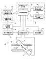
- the flow measurement device includes a flow measurement unit 10 and a measurement control unit 20, as shown in FIG.
- the flow rate measurement unit 10 includes a pair of ultrasonic transceivers 11 and 12, a transmission / reception switching unit 13, an oscillation drive unit 14, an ultrasonic detection unit 15, a propagation time measurement unit 16, and a flow rate calculation unit 17. ing.
- the pair of ultrasonic transmitters / receivers 11 and 12 are arranged to face each other across the measurement channel 30 through which the gas to be measured flows.
- the first ultrasonic transmitter / receiver 11 and the second ultrasonic transmitter / receiver 12 are arranged to face each other so as to incline and intersect the measurement flow path 30.
- the opposing direction of the first ultrasonic transmitter / receiver 11 and the second ultrasonic transmitter / receiver 12 is inclined at an angle ⁇ .
- the first ultrasonic transmitter / receiver 11 and the second ultrasonic transmitter / receiver 12 transmit and receive ultrasonic waves to each other.
- the specific configuration of the ultrasonic transmitters / receivers 11 and 12 is not limited, and a known ultrasonic oscillator that can perform both transmission and reception of ultrasonic waves can be used. In the present embodiment, a known piezoelectric ceramic vibrator is used.
- the transmission / reception switching unit 13 switches transmission / reception of the pair of ultrasonic transmitters / receivers 11 and 12 at a constant cycle under the control of the measurement control unit 20.
- the oscillation driving unit 14 drives one of the ultrasonic transceivers 11 and 12 set on the transmission side to transmit ultrasonic waves toward the other.
- the ultrasonic detector 15 detects the ultrasonic wave received by one of the ultrasonic transceivers 11 and 12 set on the receiving side.
- the oscillation driving unit 14 The ultrasonic transmitter / receiver 11 is driven to generate ultrasonic waves toward the second ultrasonic transmitter / receiver 12 (see the bidirectional arrow Ss in the figure).
- the second ultrasonic transmitter / receiver 12 receives the ultrasonic wave transmitted from the first ultrasonic transmitter / receiver 11, and the ultrasonic wave is detected by the ultrasonic detector 15. Thereafter, if the second ultrasonic transmitter / receiver 12 is set on the transmission side and the first ultrasonic transmitter / receiver 11 is set on the reception side by the transmission / reception switching unit 13, the same ultrasonic transmission / reception and detection are performed.
- the propagation time measurement unit 16 measures the propagation time of the ultrasonic wave detected by the ultrasonic wave detection unit 15. That is, if the first ultrasonic transmitter / receiver 11 is set to the transmitting side and the second ultrasonic transmitter / receiver 12 is set to the receiving side, the ultrasonic wave transmitted by the first ultrasonic transmitter / receiver 11 is the second ultrasonic wave. The time until reception by the acoustic wave transmitter / receiver 12 is measured.
- the flow rate calculation unit 17 calculates a gas flow rate value from the propagation time detected by the propagation time measurement unit 16. In this embodiment, the flow rate calculation unit 17 includes a measurement block flow rate calculation unit 171 and a sampling period flow rate calculation unit 172. The calculation of the flow rate by these flow rate calculation units 171 and 172 will be described later.
- Specific configurations of the transmission / reception switching unit 13, the oscillation driving unit 14, the ultrasonic detection unit 15, the propagation time measurement unit 16, and the flow rate calculation unit 17 are not particularly limited, and are known switching circuits in the field of ultrasonic oscillation elements, A drive circuit, a reception circuit, a measurement circuit, an arithmetic circuit, or the like can be suitably used.
- the transmission / reception switching unit 13, the oscillation driving unit 14, the ultrasonic detection unit 15, the propagation time measurement unit 16, and the flow rate calculation unit 17 may be configured as independent circuits or the like, or on a single substrate. It may be mounted and configured integrally.
- the flow rate calculation unit 17 is a calculation unit such as a CPU and a storage unit such as a memory
- the configuration of the transmission / reception switching unit 13, the oscillation drive unit 14, the ultrasonic detection unit 15, and the propagation time measurement unit 16 is configured.
- the configuration realized by the operation of the arithmetic element according to the program stored in the storage unit, that is, the functional configuration of the arithmetic element may be employed.
- the specific configuration of the flow rate measurement unit 10 is not limited to the configuration illustrated in FIG. 1, and other known configurations can be employed. Therefore, in the present invention, the flow rate measurement unit 10 only needs to be configured to measure the flow rate of the fluid by transmitting and receiving ultrasonic waves between the pair of ultrasonic transmitters and receivers 11 and 12, and the transmission / reception switching unit 13.
- the configuration may be such that at least a part of the oscillation drive unit 14, the ultrasonic detection unit 15, the propagation time measurement unit 16, and the flow rate calculation unit 17 is not provided, or a configuration that includes other components. There may be.
- the measurement control unit 20 includes a transmission / reception control unit 21, a sampling cycle setting unit 22, and a measurement block dividing unit 23.
- the transmission / reception control unit 21 controls the operations of the transmission / reception switching unit 13, the oscillation drive unit 14, the propagation time measurement unit 16, and the flow rate calculation unit 17 (specifically, the sampling period flow rate calculation unit 172).
- Ultrasonic waves are transmitted and received between the sound wave transmitter / receiver 11 and the second ultrasonic wave transmitter / receiver 12 to measure the flow rate.
- these operations may also be controlled by the transmission / reception control unit 21.
- the sampling cycle setting unit 22 sets a sampling cycle which is the minimum time unit for flow rate measurement.
- the transmission / reception control unit 21 controls the operation of the transmission / reception switching unit 13 or the like for each set sampling period to transmit / receive ultrasonic waves between the ultrasonic transmitters / receivers 11 and 12.
- the measurement block dividing unit 23 divides the sampling period into a plurality of measurement blocks. The measurement blocks are equally spaced time zones, and the measurement block dividing unit 23 divides the sampling period into three or more measurement blocks.
- the transmission / reception control unit 21 transmits / receives ultrasonic waves in each measurement block which can be said to be a lower period of the sampling period divided at equal intervals.
- the measurement control unit 20 may basically be configured to cause the flow rate measurement unit 10 to perform flow rate measurement for each sampling period, but the flow rate measurement here is calculated by flow rate measurement for each measurement block. It is not the flow rate value that is performed, but the flow rate value for the entire sampling period. If the former is called a block flow value and the latter is called a periodic flow value, the periodic flow value is calculated as an average value of the block flow values in a single sampling period.
- the transmission / reception control unit 21 includes an arithmetic element such as a CPU and a storage unit such as a memory, and the sampling period setting unit 22 and the measurement block division unit 23 are each configured by a known switching element, subtractor, comparator, or the like. It may be configured as a circuit or the like.
- the measurement control unit 20 is configured by an arithmetic element such as a CPU
- the transmission / reception control unit 21, the sampling cycle setting unit 22, and the measurement block division unit 23 may be a functional configuration of the measurement control unit 20.
- the transmission / reception control unit 21, the sampling cycle setting unit 22, and the measurement block dividing unit 23 are realized by the arithmetic element operating according to a program stored in the storage unit.
- sampling cycle and measurement block [Sampling period and measurement block] Next, the sampling cycle and measurement block, and the flow rate measurement method (including the description of the configuration of the measurement block flow rate calculation unit 171 and the sampling cycle flow rate calculation unit 172) will be described in detail with reference to FIGS. 2A and 2B. I will explain it.
- FIG. 2B a hatched region in the figure is shown for each sampling period Tc having a certain time length.
- the flow rate measurement is performed once in the flow rate measurement operation time Tm indicated by. 2A and 2B, the horizontal axis indicates the elapsed time t, and the sampling cycle Tc is illustrated in a band shape.
- the sampling period Tc is set as the minimum unit of time for flow rate measurement. This is because the power source of the guessing gas meter is not an external power supply but a built-in battery. In other words, the guessing type gas meter needs to use a power source as a battery because of its use conditions, so that if the power consumption is large, the battery will be consumed in a short period of time. Therefore, it is necessary to reduce the power consumption of the guessing gas meter as much as possible.
- the flow rate measurement needs to be performed at a frequency that can ensure the accuracy of a good gas flow rate value. Therefore, the sampling period Tc is set so that both power consumption reduction and flow rate measurement accuracy can be achieved.
- the typical sampling period Tc is set to 2 seconds as described above, but is not limited to this, and can be set to a different length depending on the use environment or the fluid to be measured.
- the start timing of the flow rate measurement operation time Tm (measurement period T in Patent Document 1) is controlled to be shifted by the time interval Td. If this time interval Td is referred to as a delay time Td in the present embodiment, the length of the delay time Td differs in each sampling cycle Tc as shown in FIG. 2B. The flow measurement is started at random.
- Ts 300 milliseconds.
- the start timing is set to be within the range of 0 milliseconds to 300 milliseconds.
- the flow measuring device is a measurement block dividing unit 23 of the measurement control unit 20 and has three or more equally-measured measurement blocks Tb (The transmission / reception control unit 21 causes the flow rate measurement unit 10 to perform flow rate measurement for each measurement block Tb.
- the transmission / reception control unit 21 causes the flow rate measurement unit 10 to perform flow rate measurement in the first to fourth measurement blocks Tb. That is, as shown in FIG. 2A, the measurement is performed on all the blocks marked with “ ⁇ ”.
- the measurement block flow rate calculation unit 171 in the flow rate calculation unit 17 calculates and stores the gas flow rate values measured in all the first to fourth measurement blocks. After that, the sampling cycle flow rate calculation unit 172 of the flow rate calculation unit 17 acquires information on the sampling cycle Tc from the transmission / reception control unit 21, and the flow rate values measured in all the first to fourth measurement blocks are Obtained from the measurement block flow rate calculator 171, calculates the average value thereof, and acquires the average value as the flow rate value of the sampling period Tc.
- FIG. 2A shows the pulsation synchronized with the sampling period Tc.
- the pulsation and the measurement block Tb are not synchronized, and the pulsation is substantially equal to the measurement block Tb.
- the flow rate can be measured randomly. Thereby, the influence of pulsation can be reduced more effectively than before, and the accuracy of flow rate measurement can be further improved.
- the flow rate measurement is not performed only once in the sampling period Tc, but the sampling period Tc is divided into a plurality of measurement blocks Tb, and the flow rate measurement is performed in all the blocks, thereby making it more than conventional. More random flow measurement can be performed.
- the flow measurement start timing in each sampling period Tc is random.
- the random start timing is within a specific period, which is a period from the start of the sampling period Tc to the maximum delay time Ts. Therefore, the flow rate can be measured more randomly in the present invention than in the prior art.
- the sampling period Tc is divided into four measurement blocks Tb.
- the number of divisions is not limited to this and may be three or more.
- the upper limit of the number of divisions is not particularly limited, and the upper limit value can be automatically determined according to various conditions such as the length of the flow rate measurement operation time Tm, the upper limit of power consumption, or the required frequency of flow rate measurement.
- the sampling period Tc may be divided into three measurement blocks Tb (see the second sampling period Tc in FIG. 3), or five measurement blocks Tb. (Refer to the fourth sampling period Tc in FIG. 3), although not shown, it may be divided into six or more measurement blocks Tb.
- the sampling period Tc is divided into four measurement blocks Tb each time.
- the first, third, and fifth sampling periods Tc are four measurement blocks.
- the second sampling period Tc is divided into three measurement blocks Tb
- the fourth sampling period Tc is divided into five measurement blocks Tb.
- the number of measurement blocks Tb (number of divisions) may be changed for each sampling period Tc as described above.
- the number of measurement blocks Tb at this time may change randomly or may change periodically in a predetermined order.
- the pair of ultrasonic transmitters / receivers 11 and 12 is configured to be opposed to the measurement channel 30 at an angle ⁇ .
- the ultrasonic waves transmitted from the transmission-side ultrasonic transceivers 11 and 12 are reflected by the inner wall of the measurement flow path 30 and received by the reception-side ultrasonic transmission / reception units 11 and 12.
- the measurement flow path 30 may be integrated with the ultrasonic transceivers 11 and 12 to constitute an ultrasonic measurement unit.
- an estimation type gas meter is exemplified as the flow rate measuring device, but the present invention is not limited to this, and includes a pair of ultrasonic transmitters / receivers, and fluid flow is performed by transmitting / receiving ultrasonic waves. It can be used widely and suitably for a flow rate measuring device for measuring a flow rate.
- Embodiment 2 A flow rate measuring apparatus according to Embodiment 2 of the present invention will be specifically described with reference to FIGS. 4 and 5.
- the flow measurement device according to the present embodiment is basically the same as the flow measurement device according to the first embodiment, but the measurement control unit 20 sets the measurement timing setting unit 24. It contains different points.
- the measurement timing setting unit 24 sets the timing of flow rate measurement performed for each measurement block.
- the transmission / reception control unit 21 performs flow rate measurement in each measurement block at the timing set by the measurement timing setting unit 24 when performing flow rate measurement for each measurement block.
- the measurement timing setting unit 24 may set the timing so that the flow measurement is always performed at the same timing in each measurement block, but is set individually so that the flow measurement timing in each measurement block is random. Then, the randomness of flow measurement can be further improved.
- the sampling period Tc is divided into four measurement blocks Tb as in the first embodiment.
- the flow rate measurement operation time Tm in each measurement block Tb is represented by a hatched area, the timing at which the flow rate measurement is performed in each of the first to fourth measurement blocks Tb is different.
- the specific configuration of the measurement timing setting unit 24 is not particularly limited. As described in the first embodiment, the measurement timing setting unit 24 is known in the same manner as the transmission / reception control unit 21, the sampling cycle setting unit 22, and the measurement block dividing unit 23. May be configured as a logic circuit using a switching element, a subtractor, a comparator, or the like, or may be a functional configuration of the measurement control unit 20 as long as the measurement control unit 20 is configured by an arithmetic element.
- the present invention can be suitably used not only in the field of gas flow rate measurement utilizing the reciprocal difference method of propagation time such as a guessing type gas meter, but also widely in the field of flow rate measurement in which pulsation may occur.
Landscapes
- Physics & Mathematics (AREA)
- Fluid Mechanics (AREA)
- General Physics & Mathematics (AREA)
- Electromagnetism (AREA)
- Measuring Volume Flow (AREA)
Abstract
流量計測装置の計測制御部は、計測ブロック分割部により、サンプリング周期Tcを3つ以上、例えば4つの等間隔な計測ブロックTbに分割し、当該計測ブロックTb毎に流量計測部に流量計測を行わせる。流量計測部の流量算出部は、サンプリング周期Tc毎に、すべての計測ブロックで得られた流量値の平均値を、当該サンプリング周期Tcの流量値として算出する。これにより、推量式ガスメータ等の伝搬時間逆数差法を利用した流量計測装置において、脈動の影響をより一層有効に軽減し、流量計測の精度のさらなる向上を図ることができる。
Description
本発明は、超音波を利用してガス等の流体の流量を計測する流量計測装置に関し、特に、前記流量計測のための最少の時間単位として設定されているサンプリング周期毎に、流量計測を行う流量計測装置に関する。
超音波を用いて流体の流量を計測する流量計測装置の一つとして、伝搬時間逆数差法を利用したものが知られている。伝搬時間逆数差法では、流量計測の対象となる流路(計測流路)の上流側および下流側のそれぞれに超音波送受波器を設け、パルス状の超音波を交互に送受信させる。これにより、順方向および逆方向それぞれの伝搬時間を利用して流体の流速を測定することができるので、当該流速と計測流路の断面積とを利用して流体の流量を計測することができる。
伝搬時間逆数差法を利用した流量計測装置の具体例としては、典型的には、推量式(あるいは推測式)ガスメータが挙げられる。推量式ガスメータは、一般に、計測流路となる配管内でガスの流量を間欠的にサンプリング計測し、その計測値の平均値を算出して積算することで、ガス使用量(流量積算値)を取得する構成となっている。なお、サンプリング計測は、基本的に、予め設定されているサンプリング周期毎に1回行われる。つまり、サンプリング周期とは、流量計測のための最少の時間単位として設定されている周期である。
前記構成の推量式ガスメータは、従来の実容量式(実測式)ガスメータ(例えば膜式ガスメータ)と比較して、流量計測のための機械的稼働部を備える必要がない。それゆえ、部品点数を削減することができるので、小型化および低コスト化が可能となっている。
ところで、ガスは、水等の液体とは異なり圧縮可能な流体であるため、ガスエンジンヒートポンプ(GHP)等のガスを圧縮させる機器を通過する過程で、ガス流に脈動が生じやすい。推量式ガスメータにおいては、この脈動がサンプリング周期に重なると、ガスの流量計測に誤差が生じることが知られている。
特に脈動が周期的に生じると、脈動の周期とサンプリング周期とが一致または近接していたり、脈動の周期がサンプリング周期の整数倍となっていたりすれば、ガスの流量値として脈動のピーク値のみまたはボトム値のみが計測されるおそれがある。このような場合には、ガスの流量値の誤差は相対的に大きなものとなり、さらに誤差を含む流量値が積算されれば、その積算値であるガス使用量が、現実の使用量から大きく外れたものとなってしまう。
そこで従来から、ガス流に脈動が生じても正確なガス流量値を得るための技術が種々提案されている。例えば、特許文献1には、計測期間の開始位相を所定の規則性に基づいて変化させる流量計測方法および流量計測装置が開示されている。具体的には、計測期間Tの間毎に時間間隔Tdを設け、複数の計測期間Tの開始タイミングの周期または位相を、実測された脈動の周期または位相と異なるように、予め定められた所定の規則性に基づいて変化させている。
ところで近年では、ガスメータの検針に通信ネットワークが利用されつつあることから、ガスメータに種々の通信機能を付与する技術が提案され、また実用化されている。伝搬時間逆数差法を利用した推量式ガスメータは、超音波の送受信によって数秒でガスの流量計測を行うことが可能である上に、計測された流量値をデジタルデータとして取得することができるため、通信機能を介して各種ネットワークに接続したり他の機器に接続してシステムを構成したりすることが可能となっている。
特に、ネットワーク接続あるいはシステム化によって推量式ガスメータをガス漏れ警報機あるいは他の警報機器に連動させれば、当該推量式ガスメータは、種々の保安機能を具備することも可能となる。このような使用状況に対応すべく、推量式ガスメータに対しては、より高い精度での流量計測が要求されつつある。
これまでの使用状況であれば、特許文献1に開示の技術を用いることで、脈動の影響を有効に軽減する推量式ガスメータを実現することが可能であった。しかしながら、特許文献1に開示の技術は、前記のとおり、個々のサンプリング周期において流量計測(計測期間T)の開始タイミングを時間間隔Tdずらす構成である。それゆえ、この構成では、例えば、単発で発生する脈動、あるいは、想定とは異なる周期の脈動が発生する場合には、十分対応できない場合があり得る。したがって、今後想定される使用状況では、脈動の影響をさらに一層軽減させる必要が生じる。
本発明はこのような課題を解決するためになされたものであって、推量式ガスメータ等の伝搬時間逆数差法を利用した流量計測装置において、脈動の影響をより一層有効に軽減し、流量計測の精度のさらなる向上を図ることを目的とする。
本発明に係る流量計測装置は、前記の課題を解決するために、測定対象となる流体が流れる計測流路に交差して対向配置される一対の超音波送受信器を含み、前記超音波送受信器の間で超音波を送受信することにより前記流体の流量計測を行う流量計測部と、前記流量計測のための最少の時間単位として設定されているサンプリング周期毎に、前記流量計測部に前記流量計測を行わせるよう制御する計測制御部と、を備え、当該計測制御部は、前記サンプリング周期を、3つ以上の等間隔な計測ブロックに分割して当該計測ブロック毎に前記流量計測部に前記流量計測を行わせるとともに、前記流量計測部は、前記サンプリング周期毎に、前記すべての計測ブロックで得られた流量値の平均値を、当該サンプリング周期の流量値として算出するよう構成されている。
前記構成の流量計測装置においては、前記計測制御部は、前記流量計測が前記計測ブロック毎にランダムなタイミングで行われるように、前記流量計測部を制御する構成であってもよい。
前記構成の流量計測装置においては、前記流量計測部は、少なくとも、前記一対の超音波送受信器と、当該超音波送受信器の送受信を切り替える送受信切替部と、送信側となる前記超音波送受信器を、超音波の送信を行わせるように駆動する発振駆動部と、受信側となる前記超音波送受信器で受信した前記超音波を検出する超音波検出部と、前記一対の超音波送受信器の間で送受信される超音波の伝搬時間を計測する伝搬時間測定部と、前記伝搬時間から前記流体の流量値を算出する流量算出部と、から構成されてもよい。
前記構成の流量計測装置においては、前記流量算出部は、前記計測ブロック毎に流量値を算出して記憶する計測ブロック流量算出部と、前記サンプリング周期毎に、前記計測ブロック流量算出部で記憶された流量値の平均値を算出する、サンプリング周期流量算出部と、から構成されてもよい。
本発明の前記目的、他の目的、特徴、及び利点は、添付図面参照の下、以下の好適な実施態様の詳細な説明から明らかにされる。
以上のように、本発明では、推量式ガスメータ等の伝搬時間逆数差法を利用した流量計測装置において、脈動の影響をより一層有効に軽減し、流量計測の精度のさらなる向上を図ることができる、という効果を奏する。
以下、本発明の好ましい実施の形態を、図面を参照しながら説明する。なお、以下では全ての図を通じて同一又は相当する要素には同一の参照符号を付して、その重複する説明を省略する。
(実施の形態1)
[流量計測装置の構成]
本発明の実施の形態1に係る流量計測装置の構成について、図1を参照して具体的に説明する。本実施の形態に係る流量計測装置は、伝搬時間逆数差法を利用した推量式ガスメータであり、測定対象となる流体はガスである。当該流量計測装置は、図1に示すように、流量計測部10および計測制御部20を備えている。
[流量計測装置の構成]
本発明の実施の形態1に係る流量計測装置の構成について、図1を参照して具体的に説明する。本実施の形態に係る流量計測装置は、伝搬時間逆数差法を利用した推量式ガスメータであり、測定対象となる流体はガスである。当該流量計測装置は、図1に示すように、流量計測部10および計測制御部20を備えている。
流量計測部10は、一対の超音波送受信器11,12と、送受信切替部13と、発振駆動部14と、超音波検出部15と、伝搬時間測定部16と、流量算出部17とを備えている。一対の超音波送受信器11,12は、測定対象のガスが流れる計測流路30に交差して対向配置される。本実施の形態では、図1に示すように、計測流路30に傾斜して交差するように、第一超音波送受信器11および第二超音波送受信器12が対向して配置されている。なお、計測流路30内のガスの流れる方向を図中矢印Fとすると、第一超音波送受信器11および第二超音波送受信器12の対向方向は角度φで傾斜している。
第一超音波送受信器11および第二超音波送受信器12は、互いに超音波の送信および受信を行う。これら超音波送受信器11,12の具体的な構成は限定されず、超音波の送信および受信の双方を行うことができる公知の超音波発振素子を用いることができる。本実施の形態では、公知の圧電セラミック振動子が用いられる。
送受信切替部13は、計測制御部20の制御により一定の周期で一対の超音波送受信器11,12の送受信を切り替える。発振駆動部14は、送信側に設定された超音波送受信器11,12の一方を駆動することにより、他方に向けて超音波を送信させる。超音波検出部15は、受信側に設定された超音波送受信器11,12の一方で受信した超音波を検出する。
より具体的には、例えば、送受信切替部13により、第一超音波送受信器11が送信側に第二超音波送受信器12が受信側に設定されていれば、発振駆動部14は、第一超音波送受信器11を駆動させ、第二超音波送受信器12に向けて超音波をさせる(図中双方向の矢印Ss参照)。第二超音波送受信器12は、第一超音波送受信器11から送信された超音波を受信し、当該超音波は超音波検出部15により検出される。その後、送受信切替部13により、第二超音波送受信器12が送信側に第一超音波送受信器11が受信側に設定されれば、同様の超音波の送受信および検出が行われる。
伝搬時間測定部16は、超音波検出部15で検出された超音波の伝搬時間を測定する。つまり、第一超音波送受信器11が送信側に第二超音波送受信器12が受信側に設定されている例であれば、第一超音波送受信器11で送信された超音波が第二超音波送受信器12で受信されるまでの時間を測定する。流量算出部17は、伝搬時間測定部16により検出された伝搬時間から、ガスの流量値を算出する。本実施の形態では、流量算出部17は、計測ブロック流量算出部171とサンプリング周期流量算出部172とから構成されている。これら流量算出部171,172による流量の算出については後述する。
送受信切替部13、発振駆動部14、超音波検出部15、伝搬時間測定部16、および流量算出部17の具体的な構成は特に限定されず、超音波発振素子の分野で公知の切替回路、駆動回路、受信回路、計測回路、演算回路等を好適に用いることができる。また、送受信切替部13、発振駆動部14、超音波検出部15、伝搬時間測定部16、および流量算出部17は、それぞれ独立した回路等として構成されてもよいし、単一の基板上に実装されて一体的に構成されてもよい。あるいは、流量算出部17がCPU等の演算素子およびメモリ等の記憶部であれば、送受信切替部13、発振駆動部14、超音波検出部15および伝搬時間測定部16の少なくとも一部の構成が、記憶部に格納されるプログラムに従って演算素子が動作することにより実現される構成、すなわち演算素子の機能構成となっていてもよい。
なお、流量計測部10の具体的構成は、図1に示す構成に限定されず、公知の他の構成を採用することができる。したがって、本発明においては、流量計測部10は、一対の超音波送受信器11,12の間で超音波を送受信することにより流体の流量計測を行うよう構成されていればよく、送受信切替部13、発振駆動部14、超音波検出部15、伝搬時間測定部16、および流量算出部17の少なくとも一部を備えていない構成であってもよいし、これら以外の構成要素を備えている構成であってもよい。
計測制御部20は、送受信制御部21、サンプリング周期設定部22、および計測ブロック分割部23から構成されている。送受信制御部21は、送受信切替部13、発振駆動部14、伝搬時間測定部16、および流量算出部17(具体的にはサンプリング周期流量算出部172)の動作を制御することにより、第一超音波送受信器11および第二超音波送受信器12の間で超音波を送受信させ、流量計測を行う。なお、超音波検出部15(および計測ブロック流量算出部171)の構成によっては、これらの動作も送受信制御部21により制御されてよい。
サンプリング周期設定部22は、流量計測のための最少の時間単位であるサンプリング周期を設定する。送受信制御部21は、設定されたサンプリング周期毎に送受信切替部13等の動作を制御して超音波送受信器11,12の間で超音波を送受信させる。計測ブロック分割部23は、サンプリング周期を複数の計測ブロックに分割する。計測ブロックは、等間隔の時間帯であって、計測ブロック分割部23は、3つ以上の計測ブロックにサンプリング周期を分割する。送受信制御部21は、等間隔に分割されたサンプリング周期の下位周期といえる計測ブロックそれぞれにおいて、超音波の送受信を行わせる。
計測制御部20は、基本的に、サンプリング周期毎に、流量計測部10に流量計測を行わせるように構成されていればよいが、ここでいう流量計測は、計測ブロック毎の流量計測で算出される流量値ではなく、サンプリング周期全体についての流量値である。前者をブロック流量値と称し、後者を周期流量値と称すれば、周期流量値は、単一のサンプリング周期におけるブロック流量値の平均値として算出される。
送受信制御部21、サンプリング周期設定部22、および計測ブロック分割部23の具体的構成は特に限定されない。例えば、送受信制御部21はCPU等の演算素子およびメモリ等の記憶部から構成され、サンプリング周期設定部22、および計測ブロック分割部23は、それぞれ公知のスイッチング素子、減算器、比較器等による論理回路等として構成されてもよい。あるいは、計測制御部20がCPU等の演算素子で構成されていれば、送受信制御部21、サンプリング周期設定部22、および計測ブロック分割部23は、計測制御部20の機能構成であってもよい。この場合、演算素子が記憶部に格納されるプログラムに従って動作することにより、送受信制御部21、サンプリング周期設定部22、および計測ブロック分割部23、が実現される。
[サンプリング周期および計測ブロック]
次に、前述したサンプリング周期および計測ブロック、並びに、流量計測の方法(計測ブロック流量算出部171およびサンプリング周期流量算出部172の構成の説明も含む)について、図2Aおよび図2Bを参照して具体的に説明する。
次に、前述したサンプリング周期および計測ブロック、並びに、流量計測の方法(計測ブロック流量算出部171およびサンプリング周期流量算出部172の構成の説明も含む)について、図2Aおよび図2Bを参照して具体的に説明する。
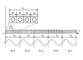
特許文献1に開示される従来の流量計測装置(以下、従来の流量計測装置と称する。)においては、図2Bに示すように、一定の時間長のサンプリング周期Tc毎に、図中斜線の領域で示される流量計測動作時間Tmで流量計測が1回行われる。なお、図2A,図2Bのいずれも横軸は経過時間tを示し、サンプリング周期Tcを帯状に図示している。本実施の形態では、例えば、サンプリング周期Tc=2秒に設定され、流量計測動作時間Tm=約200ミリ秒に設定されている。
サンプリング周期Tcは、前述したとおり、流量計測のための最少の時間単位として設定されるが、これは、推量式ガスメータの電源が外部給電ではなく内蔵型の電池であることによる。つまり、推量式ガスメータは、その使用条件から電源を電池とする必要があるので、消費電力が大きければ電池は短期間で消耗してしまう。それゆえ推量式ガスメータの消費電力は可能な限り削減する必要が生じる。一方、流量計測は、良好なガス流量値の精度を確保できる頻度で行われる必要がある。そこで、消費電力の削減および流量計測の精度を両立できるようにサンプリング周期Tcが設定される。典型的なサンプリング周期Tcは前記のとおり2秒に設定されているが、もちろんこれに限定されず、使用環境あるいは計測対象の流体に応じて異なる長さに設定することができる。
ここで、従来の流量計測装置では、前述したように、流量計測動作時間Tm(特許文献1では計測期間T)の開始タイミングを時間間隔Tdずらすように制御している。この時間間隔Tdを本実施の形態では遅延時間Tdと称すれば、この遅延時間Tdの長さは、図2Bに示すように、毎回のサンプリング周期Tcで異なっているので、毎回のサンプリング周期Tcにおいて流量計測がランダムに開始されていることになる。
ただし、従来の流量計測装置においては、遅延時間Tdの最大値は、最大遅延時間Ts(例えばTs=300ミリ秒)に設定されているので、言い換えれば、毎回のサンプリング周期Tcにおいて、流量計測の開始タイミングは、0ミリ秒~300ミリ秒の範囲内となるように設定されていることになる。
このとき、図2Bの最下段に示すように、サンプリング周期Tcと同期する脈動が発生したとする。図2Bに示す例では、脈動の立ち上がり時期が常に遅延時間Tdに重なるため、流量計測の開始をランダムに変化させたとしても、流量計測動作時間Tmが脈動に同期してしまう。これまでの使用環境では、従来の流量計測装置であっても実用に耐え得る良好な計測精度を確保できたが、今後想定される使用状況では、脈動の影響をさらに一層軽減させる必要が生じる。
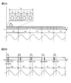
これに対して、本実施の形態に係る流量計測装置は、図2Aに示すように、計測制御部20の計測ブロック分割部23で、サンプリング周期Tcを3つ以上の等間隔な計測ブロックTb(図2Aでは4つ)に分割し、送受信制御部21は、当該計測ブロックTb毎に流量計測部10に流量計測を行わせる。
例えば、図2Aにおける最初のサンプリング周期Tcを拡大した上段に示すように、計測ブロック分割部23によってサンプリング周期Tcが4つの計測ブロックTb(Tb=0.5秒)に分割されている。
送受信制御部21は、1番目~4番目の計測ブロックTbにおいて流量計測部10に流量計測を行わせる。すなわち図2Aに示すように「○」と表記されたすべてのブロックで計測が行われる。
そして、流量算出部17のうち計測ブロック流量算出部171は、1番目~4番目のすべての計測ブロックで計測されたガスの流量値を算出して記憶する。その後、流量算出部17のうちサンプリング周期流量算出部172は、送受信制御部21からのサンプリング周期Tcに関する情報を取得し、1番目~4番目のすべての計測ブロックで流量計測された流量値を、計測ブロック流量算出部171から取得し、これらの平均値を算出して、当該平均値をサンプリング周期Tcの流量値として取得する。
そして、図2Aの最下段には、サンプリング周期Tcと同期する脈動を示しているが、図2Aから明らかなように、脈動と計測ブロックTbとは同期することがなく、計測ブロックTbにより実質的にランダムに流量計測を行うことができる。これにより、従来よりも脈動の影響をより一層有効に軽減し、流量計測の精度のさらなる向上を図ることができる。
つまり、本発明においては、サンプリング周期Tcで1回のみ流量計測を行うのではなく、サンプリング周期Tcを複数の計測ブロックTbに分割し、そのすべてのブロックで流量計測を行うことで、従来よりも一層ランダムな流量計測を行うことができる。
図2Bに示すように、従来では、サンプリング周期Tc毎に流量計測の開始時間をずらしているので、個々のサンプリング周期Tcにおける流量計測の開始タイミングはランダムになる。ところが、連続するサンプリング周期Tc全体としてみれば、ランダムな開始タイミングは、サンプリング周期Tcの開始から最大遅延時間Tsまでの期間という、特定の周期内に収まっていることになる。それゆえ、従来よりも本発明の方が流量計測をより一層ランダムに行うことが可能となっている。
また、本実施の形態においては、サンプリング周期Tcは、4つの計測ブロックTbに分割されているが、分割数はこれに限定されず、3つ以上であればよい。分割数の上限は特に限定されず、流量計測動作時間Tmの長さ、消費電力の上限、あるいは要求される流量計測の頻度等といった種々の条件に応じて自ずと上限値が決定され得る。具体的には、例えば、図3に示すように、サンプリング周期Tcは3つの計測ブロックTbに分割されてもよいし(図3の2番目のサンプリング周期Tc参照)、あるいは、5つの計測ブロックTbに分割されてもよいし(図3の4番目のサンプリング周期Tc参照)、図示しないが、6つ以上の計測ブロックTbに分割されてもよい。
また、図2に示す例では、サンプリング周期Tcは毎回4つの計測ブロックTbに分割されているが、図3に示す例では、1番目、3番目および5番目のサンプリング周期Tcが4つの計測ブロックTbに分割され、2番目のサンプリング周期Tcが3つの計測ブロックTbに分割され、4番目のサンプリング周期Tcが5つの計測ブロックTbに分割されている。本発明では、このようにサンプリング周期Tc毎に計測ブロックTbの数(分割数)を変化させてもよい。このときの計測ブロックTbの数は、ランダムに変化してもよいし、所定の順序で周期的に変化してもよい。
また、本実施の形態では、一対の超音波送受信器11,12は計測流路30に角度φで交差して対向配置される構成となっているが、例えば、計測流路30の同じ側に配置される構成であってもよい。この構成では、送信側の超音波送受信器11,12からされた超音波が、計測流路30の内壁で反射されて受信側の超音波送受信器11,12で受信されることになる。また、計測流路30は、超音波送受信器11,12とともに一体化されて超音波計測ユニットを構成してもよい。
さらに、本実施の形態では、流量計測装置として推量式ガスメータを例示しているが、本発明はこれに限定されるものではなく、一対の超音波送受信器を備え、超音波の送受信により流体の流量を計測する流量計測装置に広く好適に用いることができる。
(実施の形態2)
本発明の実施の形態2に係る流量計測装置について、図4および図5を参照して具体的に説明する。本実施の形態に係る流量計測装置は、図4に示すように、基本的には前記実施の形態1に係る流量計測装置と同様であるが、計測制御部20が、計測タイミング設定部24を含んでいる点が異なっている。
本発明の実施の形態2に係る流量計測装置について、図4および図5を参照して具体的に説明する。本実施の形態に係る流量計測装置は、図4に示すように、基本的には前記実施の形態1に係る流量計測装置と同様であるが、計測制御部20が、計測タイミング設定部24を含んでいる点が異なっている。
計測タイミング設定部24は、計測ブロック毎に行われる流量計測のタイミングを設定する。送受信制御部21は、計測ブロック毎に流量計測を行うときに、計測タイミング設定部24で設定されたタイミングで各計測ブロックでの流量計測を行う。このとき、計測タイミング設定部24は、各計測ブロックで常に同じタイミングで流量計測を行うようにタイミング設定してもよいが、各計測ブロックでの流量計測のタイミングがランダムになるように個々に設定すると、流量計測のランダム性をより一層向上させることができる。
具体的には、前記実施の形態1と同様に、サンプリング周期Tcが4つの計測ブロックTbに分割されたとする。図5に示すように、各計測ブロックTbにおける流量計測動作時間Tmを斜線の領域で表せば1番目~4番目の各計測ブロックTbで流量計測の行われるタイミングが異なっている。
このように、計測ブロック毎に流量計測のタイミングを変えることで、脈動が計測ブロックTbの長さに同期する程度に短くても、当該脈動と流量計測動作時間Tmとが同期する可能性を低下させることができる。
なお、計測タイミング設定部24の具体的な構成は特に限定されず、前記実施の形態1で説明したとおり、送受信制御部21、サンプリング周期設定部22、および計測ブロック分割部23と同様に、公知のスイッチング素子、減算器、比較器等による論理回路等として構成されてもよいし、計測制御部20が演算素子で構成されていれば計測制御部20の機能構成であってもよい。
前記説明から、当業者にとっては、本発明の多くの改良や他の実施形態が明らかである。従って、前記説明は、例示としてのみ解釈されるべきであり、本発明を実行する最良の態様を当業者に教示する目的で提供されたものである。本発明の精神を逸脱することなく、その構造及び/又は機能の詳細を実質的に変更できる。
本発明は、推量式ガスメータ等の伝搬時間逆数差法を利用したガスの流量計測の分野に好適に用いることができるだけでなく、脈動が生じ得る流量の計測の分野に広く用いることができる。
10 流量計測部
11 第一超音波送受信器
12 第二超音波送受信器
13 送受信切替部
14 発振駆動部
15 超音波検出部
16 伝搬時間測定部
17 流量算出部
20 計測制御部
21 送受信制御部
22 サンプリング周期設定部
23 計測ブロック分割部
24 計測タイミング設定部
30 計測流路
171 計測ブロック流量算出部
172 サンプリング周期流量算出部
Tc サンプリング周期
Tb 計測ブロック
11 第一超音波送受信器
12 第二超音波送受信器
13 送受信切替部
14 発振駆動部
15 超音波検出部
16 伝搬時間測定部
17 流量算出部
20 計測制御部
21 送受信制御部
22 サンプリング周期設定部
23 計測ブロック分割部
24 計測タイミング設定部
30 計測流路
171 計測ブロック流量算出部
172 サンプリング周期流量算出部
Tc サンプリング周期
Tb 計測ブロック
Claims (4)
- 測定対象となる流体が流れる計測流路に交差して対向配置される一対の超音波送受信器を含み、前記超音波送受信器の間で超音波を送受信することにより前記流体の流量計測を行う流量計測部と、
前記流量計測のための最少の時間単位として設定されているサンプリング周期毎に、前記流量計測部に前記流量計測を行わせるよう制御する計測制御部と、を備え、
当該計測制御部は、前記サンプリング周期を、3つ以上の等間隔な計測ブロックに分割して当該計測ブロック毎に前記流量計測部に前記流量計測を行わせるとともに、
前記流量計測部は、前記サンプリング周期毎に、前記すべての計測ブロックで得られた流量値の平均値を、当該サンプリング周期の流量値として算出するよう構成されている、
流量計測装置。 - 前記計測制御部は、前記流量計測が前記計測ブロック毎にランダムなタイミングで行われるように、前記流量計測部を制御する、
請求項1に記載の流量計測装置。 - 前記流量計測部は、少なくとも、
前記一対の超音波送受信器と、
当該超音波送受信器の送受信を切り替える送受信切替部と、
送信側となる前記超音波送受信器を、超音波の送信を行わせるように駆動する発振駆動部と、
受信側となる前記超音波送受信器で受信した前記超音波を検出する超音波検出部と、
前記一対の超音波送受信器の間で送受信される超音波の伝搬時間を計測する伝搬時間測定部と、
前記伝搬時間から前記流体の流量値を算出する流量算出部と、から構成されている、
請求項1に記載の流量計測装置。 - 前記流量算出部は、
前記計測ブロック毎に流量値を算出して記憶する計測ブロック流量算出部と、
前記サンプリング周期毎に、前記計測ブロック流量算出部で記憶された流量値の平均値を算出する、サンプリング周期流量算出部と、から構成されている、
請求項1に記載の流量計測装置。
Priority Applications (3)
| Application Number | Priority Date | Filing Date | Title |
|---|---|---|---|
| US14/373,827 US9983036B2 (en) | 2012-01-23 | 2013-01-11 | Flow meter device |
| EP13740709.4A EP2808657B1 (en) | 2012-01-23 | 2013-01-11 | Flow measurement device |
| CN201380004201.2A CN103988055B (zh) | 2012-01-23 | 2013-01-11 | 流量测量装置 |
Applications Claiming Priority (2)
| Application Number | Priority Date | Filing Date | Title |
|---|---|---|---|
| JP2012010654A JP2013148523A (ja) | 2012-01-23 | 2012-01-23 | 流量計測装置 |
| JP2012-010654 | 2012-01-23 |
Publications (1)
| Publication Number | Publication Date |
|---|---|
| WO2013111527A1 true WO2013111527A1 (ja) | 2013-08-01 |
Family
ID=48873261
Family Applications (1)
| Application Number | Title | Priority Date | Filing Date |
|---|---|---|---|
| PCT/JP2013/000100 Ceased WO2013111527A1 (ja) | 2012-01-23 | 2013-01-11 | 流量計測装置 |
Country Status (5)
| Country | Link |
|---|---|
| US (1) | US9983036B2 (ja) |
| EP (1) | EP2808657B1 (ja) |
| JP (1) | JP2013148523A (ja) |
| CN (1) | CN103988055B (ja) |
| WO (1) | WO2013111527A1 (ja) |
Families Citing this family (10)
| Publication number | Priority date | Publication date | Assignee | Title |
|---|---|---|---|---|
| CN104864923A (zh) * | 2014-02-24 | 2015-08-26 | 通用电气公司 | 传送和接收超声信号的电路组件及使用该电路组件的系统和方法 |
| DE102016112295B4 (de) * | 2016-07-05 | 2019-01-24 | Sick Engineering Gmbh | Ultraschallmessvorrichtung und Verfahren zum Messen der Strömungsgeschwindigkeit eines Fluids |
| JP7012218B2 (ja) * | 2018-03-30 | 2022-01-28 | パナソニックIpマネジメント株式会社 | ガス保安装置 |
| JP7203355B2 (ja) * | 2019-12-26 | 2023-01-13 | パナソニックIpマネジメント株式会社 | ガスメータ |
| US11340099B2 (en) * | 2020-03-26 | 2022-05-24 | Itron Global Sarl | Static fluid meter |
| CN112033479B (zh) * | 2020-08-11 | 2023-02-03 | 江苏水科尚禹能源技术研究院有限公司 | 一种生态流量监测数据采集及处理方法 |
| KR102786804B1 (ko) * | 2021-10-01 | 2025-03-25 | 세메스 주식회사 | 유량 제어 장치 및 유량 제어 방법 |
| CN114413986B (zh) * | 2022-01-21 | 2026-01-30 | 深圳友讯达科技股份有限公司 | 一种燃气表计量方法及系统 |
| CN115388965A (zh) * | 2022-08-12 | 2022-11-25 | 苏州诚一物联科技有限公司 | 一种气体超声流量传感器的测量算法 |
| CN115497263B (zh) * | 2022-09-21 | 2023-11-28 | 金卡智能集团股份有限公司 | 燃气检测方法和设备 |
Citations (3)
| Publication number | Priority date | Publication date | Assignee | Title |
|---|---|---|---|---|
| JPH11258018A (ja) * | 1998-03-16 | 1999-09-24 | Yazaki Corp | 流量計測方法及び装置、脈流検出方法、並びに電子式ガスメータ |
| JP2001174306A (ja) | 1999-12-21 | 2001-06-29 | Tokyo Gas Co Ltd | 流量計測方法および流量計測装置 |
| JP2001241984A (ja) * | 2000-03-01 | 2001-09-07 | Matsushita Electric Ind Co Ltd | ガス保安装置 |
Family Cites Families (10)
| Publication number | Priority date | Publication date | Assignee | Title |
|---|---|---|---|---|
| EP0179541A3 (en) | 1984-10-19 | 1987-08-26 | Smith Meter Inc. | Sonic flow meter |
| US5277070A (en) | 1991-08-01 | 1994-01-11 | Xecutek Corporation | Ultrasonic gas flow measurement method and apparatus |
| JPH08122117A (ja) * | 1994-10-19 | 1996-05-17 | Matsushita Electric Ind Co Ltd | 流量計測装置 |
| DE19653184C2 (de) * | 1996-12-19 | 1999-10-14 | Bailey Fischer & Porter Gmbh | Signalverarbeitungsschaltung für eine Durchflußmeßeinrichtung |
| EP1243901A4 (en) | 1999-06-24 | 2006-07-05 | Matsushita Electric Industrial Co Ltd | FLOW METER |
| CN101464171B (zh) | 2007-12-18 | 2010-12-01 | 深圳职业技术学院 | 一种超声波流量检测方法 |
| CN102272560B (zh) * | 2009-01-06 | 2013-08-07 | 松下电器产业株式会社 | 流量测量装置 |
| CN102549394B (zh) * | 2009-09-30 | 2014-02-19 | 松下电器产业株式会社 | 流量测量装置 |
| US8671775B2 (en) * | 2009-12-16 | 2014-03-18 | Panasonic Corporation | Flow rate measuring device |
| JP5753970B2 (ja) * | 2010-10-22 | 2015-07-22 | パナソニックIpマネジメント株式会社 | 流量計測装置 |
-
2012
- 2012-01-23 JP JP2012010654A patent/JP2013148523A/ja active Pending
-
2013
- 2013-01-11 US US14/373,827 patent/US9983036B2/en active Active
- 2013-01-11 WO PCT/JP2013/000100 patent/WO2013111527A1/ja not_active Ceased
- 2013-01-11 EP EP13740709.4A patent/EP2808657B1/en active Active
- 2013-01-11 CN CN201380004201.2A patent/CN103988055B/zh active Active
Patent Citations (3)
| Publication number | Priority date | Publication date | Assignee | Title |
|---|---|---|---|---|
| JPH11258018A (ja) * | 1998-03-16 | 1999-09-24 | Yazaki Corp | 流量計測方法及び装置、脈流検出方法、並びに電子式ガスメータ |
| JP2001174306A (ja) | 1999-12-21 | 2001-06-29 | Tokyo Gas Co Ltd | 流量計測方法および流量計測装置 |
| JP2001241984A (ja) * | 2000-03-01 | 2001-09-07 | Matsushita Electric Ind Co Ltd | ガス保安装置 |
Also Published As
| Publication number | Publication date |
|---|---|
| EP2808657A1 (en) | 2014-12-03 |
| CN103988055A (zh) | 2014-08-13 |
| EP2808657B1 (en) | 2020-12-02 |
| EP2808657A4 (en) | 2015-07-22 |
| JP2013148523A (ja) | 2013-08-01 |
| US20140345391A1 (en) | 2014-11-27 |
| US9983036B2 (en) | 2018-05-29 |
| CN103988055B (zh) | 2018-03-13 |
Similar Documents
| Publication | Publication Date | Title |
|---|---|---|
| WO2013111527A1 (ja) | 流量計測装置 | |
| CN103180694B (zh) | 流量测量装置 | |
| JP5524972B2 (ja) | 流量計測装置 | |
| RU2014111080A (ru) | Система и способ объединения расположенных рядом расходомеров | |
| JP2012127663A (ja) | 流量計測装置 | |
| JP2009216643A (ja) | 超音波流量計 | |
| JP4788235B2 (ja) | 流体の流れ計測装置 | |
| JP2012145451A (ja) | 流量計測装置 | |
| JP2012145452A (ja) | 流量計測装置 | |
| JPH09304139A (ja) | 流量計測装置 | |
| JP4973035B2 (ja) | 超音波流量計 | |
| JP5034510B2 (ja) | 流速または流量計測装置とそのプログラム | |
| JP7203355B2 (ja) | ガスメータ | |
| JP3443657B2 (ja) | 流量計測装置 | |
| JP2008175668A (ja) | 流体の流れ計測装置 | |
| JP2008175667A (ja) | 流体の流れ計測装置 | |
| JP2008180566A (ja) | 流速または流量計測装置とそのプログラム | |
| JP2010160005A (ja) | 流量計測装置 | |
| JP5092413B2 (ja) | 流速または流量計測装置 | |
| JP2004069522A (ja) | 流量計測制御装置 | |
| JP2014013206A (ja) | 超音波計測装置 | |
| JP2003315124A (ja) | 超音波流量計 | |
| JP5548951B2 (ja) | 流量計測装置 | |
| JP2003156373A (ja) | 超音波流量計の流量変動検出装置及び超音波流量計 | |
| JP2000221068A (ja) | 超音波流速測定方法 |
Legal Events
| Date | Code | Title | Description |
|---|---|---|---|
| 121 | Ep: the epo has been informed by wipo that ep was designated in this application |
Ref document number: 13740709 Country of ref document: EP Kind code of ref document: A1 |
|
| WWE | Wipo information: entry into national phase |
Ref document number: 14373827 Country of ref document: US Ref document number: 2013740709 Country of ref document: EP |
|
| NENP | Non-entry into the national phase |
Ref country code: DE |