WO2013111613A1 - 建設機械 - Google Patents
建設機械 Download PDFInfo
- Publication number
- WO2013111613A1 WO2013111613A1 PCT/JP2013/050185 JP2013050185W WO2013111613A1 WO 2013111613 A1 WO2013111613 A1 WO 2013111613A1 JP 2013050185 W JP2013050185 W JP 2013050185W WO 2013111613 A1 WO2013111613 A1 WO 2013111613A1
- Authority
- WO
- WIPO (PCT)
- Prior art keywords
- engine
- temperature
- rotation speed
- control
- rotational speed
- Prior art date
- Legal status (The legal status is an assumption and is not a legal conclusion. Google has not performed a legal analysis and makes no representation as to the accuracy of the status listed.)
- Ceased
Links
Images


Classifications
-
- E—FIXED CONSTRUCTIONS
- E02—HYDRAULIC ENGINEERING; FOUNDATIONS; SOIL SHIFTING
- E02F—DREDGING; SOIL-SHIFTING
- E02F9/00—Component parts of dredgers or soil-shifting machines, not restricted to one of the kinds covered by groups E02F3/00 - E02F7/00
- E02F9/20—Drives; Control devices
- E02F9/22—Hydraulic or pneumatic drives
- E02F9/2246—Control of prime movers, e.g. depending on the hydraulic load of work tools
-
- E—FIXED CONSTRUCTIONS
- E02—HYDRAULIC ENGINEERING; FOUNDATIONS; SOIL SHIFTING
- E02F—DREDGING; SOIL-SHIFTING
- E02F3/00—Dredgers; Soil-shifting machines
- E02F3/04—Dredgers; Soil-shifting machines mechanically-driven
- E02F3/28—Dredgers; Soil-shifting machines mechanically-driven with digging tools mounted on a dipper- or bucket-arm, i.e. there is either one arm or a pair of arms, e.g. dippers, buckets
- E02F3/30—Dredgers; Soil-shifting machines mechanically-driven with digging tools mounted on a dipper- or bucket-arm, i.e. there is either one arm or a pair of arms, e.g. dippers, buckets with a dipper-arm pivoted on a cantilever beam, i.e. boom
- E02F3/32—Dredgers; Soil-shifting machines mechanically-driven with digging tools mounted on a dipper- or bucket-arm, i.e. there is either one arm or a pair of arms, e.g. dippers, buckets with a dipper-arm pivoted on a cantilever beam, i.e. boom working downwardly and towards the machine, e.g. with backhoes
- E02F3/325—Backhoes of the miniature type
-
- E—FIXED CONSTRUCTIONS
- E02—HYDRAULIC ENGINEERING; FOUNDATIONS; SOIL SHIFTING
- E02F—DREDGING; SOIL-SHIFTING
- E02F9/00—Component parts of dredgers or soil-shifting machines, not restricted to one of the kinds covered by groups E02F3/00 - E02F7/00
- E02F9/20—Drives; Control devices
- E02F9/22—Hydraulic or pneumatic drives
- E02F9/2278—Hydraulic circuits
- E02F9/2285—Pilot-operated systems
-
- E—FIXED CONSTRUCTIONS
- E02—HYDRAULIC ENGINEERING; FOUNDATIONS; SOIL SHIFTING
- E02F—DREDGING; SOIL-SHIFTING
- E02F9/00—Component parts of dredgers or soil-shifting machines, not restricted to one of the kinds covered by groups E02F3/00 - E02F7/00
- E02F9/20—Drives; Control devices
- E02F9/22—Hydraulic or pneumatic drives
- E02F9/2278—Hydraulic circuits
- E02F9/2296—Systems with a variable displacement pump
-
- F—MECHANICAL ENGINEERING; LIGHTING; HEATING; WEAPONS; BLASTING
- F02—COMBUSTION ENGINES; HOT-GAS OR COMBUSTION-PRODUCT ENGINE PLANTS
- F02D—CONTROLLING COMBUSTION ENGINES
- F02D1/00—Controlling fuel-injection pumps, e.g. of high pressure injection type
- F02D1/16—Adjustment of injection timing
-
- F—MECHANICAL ENGINEERING; LIGHTING; HEATING; WEAPONS; BLASTING
- F02—COMBUSTION ENGINES; HOT-GAS OR COMBUSTION-PRODUCT ENGINE PLANTS
- F02D—CONTROLLING COMBUSTION ENGINES
- F02D29/00—Controlling engines, such controlling being peculiar to the devices driven thereby, the devices being other than parts or accessories essential to engine operation, e.g. controlling of engines by signals external thereto
- F02D29/02—Controlling engines, such controlling being peculiar to the devices driven thereby, the devices being other than parts or accessories essential to engine operation, e.g. controlling of engines by signals external thereto peculiar to engines driving vehicles; peculiar to engines driving variable pitch propellers
-
- F—MECHANICAL ENGINEERING; LIGHTING; HEATING; WEAPONS; BLASTING
- F02—COMBUSTION ENGINES; HOT-GAS OR COMBUSTION-PRODUCT ENGINE PLANTS
- F02D—CONTROLLING COMBUSTION ENGINES
- F02D31/00—Use of speed-sensing governors to control combustion engines, not otherwise provided for
- F02D31/001—Electric control of rotation speed
- F02D31/007—Electric control of rotation speed controlling fuel supply
- F02D31/008—Electric control of rotation speed controlling fuel supply for idle speed control
-
- F—MECHANICAL ENGINEERING; LIGHTING; HEATING; WEAPONS; BLASTING
- F02—COMBUSTION ENGINES; HOT-GAS OR COMBUSTION-PRODUCT ENGINE PLANTS
- F02D—CONTROLLING COMBUSTION ENGINES
- F02D41/00—Electrical control of supply of combustible mixture or its constituents
- F02D41/02—Circuit arrangements for generating control signals
- F02D41/04—Introducing corrections for particular operating conditions
- F02D41/06—Introducing corrections for particular operating conditions for engine starting or warming up
- F02D41/062—Introducing corrections for particular operating conditions for engine starting or warming up for starting
- F02D41/064—Introducing corrections for particular operating conditions for engine starting or warming up for starting at cold start
-
- F—MECHANICAL ENGINEERING; LIGHTING; HEATING; WEAPONS; BLASTING
- F02—COMBUSTION ENGINES; HOT-GAS OR COMBUSTION-PRODUCT ENGINE PLANTS
- F02D—CONTROLLING COMBUSTION ENGINES
- F02D1/00—Controlling fuel-injection pumps, e.g. of high pressure injection type
- F02D1/16—Adjustment of injection timing
- F02D2001/167—Adjustment of injection timing by means dependent on engine working temperature, e.g. at cold start
-
- F—MECHANICAL ENGINEERING; LIGHTING; HEATING; WEAPONS; BLASTING
- F02—COMBUSTION ENGINES; HOT-GAS OR COMBUSTION-PRODUCT ENGINE PLANTS
- F02D—CONTROLLING COMBUSTION ENGINES
- F02D2200/00—Input parameters for engine control
- F02D2200/02—Input parameters for engine control the parameters being related to the engine
- F02D2200/021—Engine temperature
-
- F—MECHANICAL ENGINEERING; LIGHTING; HEATING; WEAPONS; BLASTING
- F02—COMBUSTION ENGINES; HOT-GAS OR COMBUSTION-PRODUCT ENGINE PLANTS
- F02D—CONTROLLING COMBUSTION ENGINES
- F02D2250/00—Engine control related to specific problems or objectives
- F02D2250/02—Fuel evaporation in fuel rails, e.g. in common rails
-
- F—MECHANICAL ENGINEERING; LIGHTING; HEATING; WEAPONS; BLASTING
- F02—COMBUSTION ENGINES; HOT-GAS OR COMBUSTION-PRODUCT ENGINE PLANTS
- F02D—CONTROLLING COMBUSTION ENGINES
- F02D41/00—Electrical control of supply of combustible mixture or its constituents
- F02D41/02—Circuit arrangements for generating control signals
- F02D41/04—Introducing corrections for particular operating conditions
- F02D41/06—Introducing corrections for particular operating conditions for engine starting or warming up
- F02D41/062—Introducing corrections for particular operating conditions for engine starting or warming up for starting
- F02D41/065—Introducing corrections for particular operating conditions for engine starting or warming up for starting at hot start or restart
-
- F—MECHANICAL ENGINEERING; LIGHTING; HEATING; WEAPONS; BLASTING
- F02—COMBUSTION ENGINES; HOT-GAS OR COMBUSTION-PRODUCT ENGINE PLANTS
- F02N—STARTING OF COMBUSTION ENGINES; STARTING AIDS FOR SUCH ENGINES, NOT OTHERWISE PROVIDED FOR
- F02N11/00—Starting of engines by means of electric motors
- F02N11/10—Safety devices
- F02N11/106—Safety devices for stopping or interrupting starter actuation
Definitions
- the present invention relates to a construction machine such as a hydraulic shovel equipped with an electronically controlled engine.
- the engine of the construction machine has a configuration in which the output shaft is directly connected to the hydraulic pump serving as a hydraulic pressure source, and the hydraulic pump is rotationally driven from the start of the engine.
- the hydraulic pump continues to suck and discharge the low-temperature, high-viscosity hydraulic oil from the beginning of the start.
- the hydraulic oil sucked into the hydraulic pump from the hydraulic oil tank tends to have a negative pressure, which tends to cause air bubbles and cavitation, which reduces the durability and the life of the hydraulic device.
- the target rotation number of the engine is variably controlled in the range from low idle rotation number to high idle rotation number. For this reason, when the low temperature start of the engine is performed while the dial of the rotation speed setting device is operated to the high idle side, the engine rotation speed rapidly rises to the high idle rotation speed, and There is a problem that bubbles and cavitation easily occur.
- the present invention has been made in view of the above-described problems of the prior art, and an object of the present invention is to realize stable start control of an engine by suppressing generation of cavitation due to hydraulic oil at the time of low temperature start of the engine.
- the goal is to provide construction equipment that can be used.
- the present invention detects an engine supplied with injection fuel by an electronically controlled fuel injection device, a temperature state detector for detecting a temperature state of the engine, and detecting the number of revolutions of the engine
- a rotational speed setting device for setting a target rotational speed of the engine
- a control device for controlling the drive of the engine based on signals from the temperature condition detector, the rotational speed detection device and the rotational speed setting device Applied to a construction machine comprising: a variable displacement hydraulic pump driven by the engine to discharge pressurized oil and subjected to torque limitation control; and a hydraulic actuator driven by pressurized oil discharged from the hydraulic pump Ru.
- the feature of the configuration adopted by the present invention is that the control device determines whether the temperature at the start of the engine has dropped to a predetermined temperature determined in advance based on the detection signal output from the temperature condition detector.
- the start-time temperature determination processing means for determining the start-up temperature determination processing means the start control of the engine is performed according to the set value of the target rotation speed by the rotation speed setting device. It comprises in having the start control processing means to perform.
- the start control processing means of the control device performs the start control of the engine according to the set value of the engine rotational speed by the rotational speed setting device when the temperature at the start-up temperature judgment processing means determines that the temperature is below the predetermined temperature. It is possible to prevent the occurrence of cavitation in the hydraulic oil and to prevent damage to the hydraulic pump.
- the start control processing means starts the engine according to the setting value at this time when the setting value of the target rotation speed by the rotation speed setting device is equal to or less than a predetermined threshold.
- the set value of the setting device is higher than the threshold value, the start of the engine is stopped, or the start control of the engine is performed according to a preset temporary set value for engine start.
- the engine can be started at a relatively low rotation speed when the setting value of the target rotation speed by the rotation speed setting device is equal to or less than a predetermined threshold value, and the rotation of the hydraulic pump It can be kept low to suppress the occurrence of cavitation.
- the setting value of the rotation speed setting device is higher than the threshold value, the occurrence of cavitation can be suppressed by stopping the start of the engine.
- start control of the engine can be performed according to a temporary set value for starting the engine, which is set in advance, and the rotation of the hydraulic pump can be suppressed low to suppress the occurrence of cavitation.
- the start control processing means starts the engine according to the setting value at this time when the setting value of the target rotation speed by the rotation speed setting device is equal to or less than a predetermined threshold.
- the setting value of the target rotation speed by the number setting device is higher than the threshold value, the starting of the engine is performed according to a temporary setting value for engine starting preset to a value lower than the setting value of the rotation speed setting device. It is set as the structure which controls.
- the temporary setting value for engine starting set in advance (that is, a temporary value lower than the setting value of the rotation speed setting device)
- the start control of the engine can be performed according to the setting value of (1), and the rotation of the hydraulic pump can be suppressed low to suppress the occurrence of cavitation.
- the threshold is a pump cavitation limit rotational speed as a limit value that increases the possibility that air bubbles are generated in the hydraulic oil to cause cavitation when the hydraulic pump rotates at the time of cold start of the engine. is there.
- the control device determines the temperature after start-up to determine whether or not the temperature of the engine has risen to the determination temperature above the predetermined temperature according to the detection signal from the temperature condition detector after the start of the engine
- the post-startup rotation which controls the number of revolutions of the engine according to the set value of the target number of revolutions by the revolution number setting device
- a number control processing means determines the temperature after start-up to determine whether or not the temperature of the engine has risen to the determination temperature above the predetermined temperature according to the detection signal from the temperature condition detector after the start of the engine.
- the after-start temperature determination processing means operates with the temperature rise when the temperature of the engine (for example, the coolant temperature or the temperature of the hydraulic oil) rises to the determination temperature after the engine start It can be judged that the viscosity of oil decreases and the possibility of cavitation generation is low. Therefore, in this case, after start-up, the engine speed control processing means can control the engine speed according to the set value of the target speed by the engine speed setting device after the start of the engine. That is, the operator can perform engine control at the rotation speed according to the setting value of the target rotation speed by manually operating the rotation speed setting device.
- the post-startup rotational speed control process determines that the temperature has risen to the determination temperature by the post-startup temperature determination processing means, in accordance with the set value of the target rotational speed by the rotational speed setting device. It is configured to automatically restore the engine speed. As a result, after starting the engine, the engine speed can be automatically returned to the set value of the target speed by the speed setting device, and thereafter, the engine control can be performed at the speed according to the manual operation of the operator it can.
- the start control processing means of the control device sets the target rotation speed set value by the rotation speed setting device to low idle when the start-up temperature judgment processing means judges that the temperature is lower than a predetermined temperature.
- the engine is temporarily fixed at a value corresponding to the rotational speed, and start control of the engine is performed according to the fixed setting value, and the control device is controlled by the detection signal from the temperature condition detector after the engine is started.
- start-up temperature determination processing means for determining whether the temperature has risen to the determination temperature above the predetermined temperature
- the post-startup temperature determination processing means determines that the temperature has risen to the determination temperature It is configured to have after-start rotation speed control processing means for releasing control of the engine rotation speed by the set value.
- the start control of the engine is performed according to the fixed set value corresponding to the low idle rotational speed.
- the engine speed can be kept low at engine start.
- the control of the engine speed by the fixed set value can be released.
- the start-up rotational speed control processing means determines that the temperature has risen to the judged temperature by the post-startup temperature judgment processing means
- the operator sets the set value of the rotational speed setting device to the low value.
- the control of the engine speed by the fixed set value is continued until it is changed to the value corresponding to the idle speed, and the control of the engine speed by the fixed set value is canceled when the operator performs the change operation. There is.
- the control of the engine speed by the fixed set value can be continued until the operator changes the setting value of the rotation speed setting device to a value corresponding to the low idle rotation speed.
- the control of the engine speed by the fixed set value can be released.
- the engine speed can be variably controlled at the speed according to the manual operation of the operator (that is, the range from the low idle speed to the high idle speed).
- the after-starting rotational speed control processing means sets the rotational speed of the engine according to the set value of the target rotational speed by the rotational speed setting device. It has a configuration to control. As a result, after the control of the target rotational speed by the fixed set value is released, the engine rotational speed can be controlled according to the set value of the target rotational speed by the rotational speed setting device, and the operator manually operates the rotational speed setting device By operation, engine control can be performed at the number of revolutions according to the set value of the target number of revolutions.
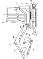
- FIG. 1 is a front view showing a hydraulic shovel according to a first embodiment of the present invention. It is a top view of the partially broken figure which expands and shows a hydraulic shovel in the state which removed a cab and some exterior covers among the upper revolving superstructures in FIG.
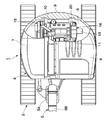
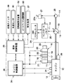
- FIG. 2 is an overall configuration diagram showing an engine, a hydraulic pump, a control valve, a hydraulic actuator, an exhaust gas purification device, a control device, and the like. It is a front view which shows the operation dial used as a rotation speed setting apparatus in FIG. It is a characteristic diagram which shows the relationship between the setting value of the engine rotation speed by the rotation speed setting device, and a target rotation speed.
- FIG. 1 is a front view showing a hydraulic shovel according to a first embodiment of the present invention. It is a top view of the partially broken figure which expands and shows a hydraulic shovel in the state which removed a cab and some exterior covers among the upper revolving superstructures in FIG.
- FIG. 2 is an overall
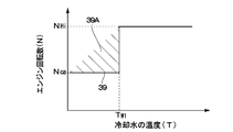
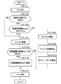
- FIG. 6 is a characteristic diagram showing the relationship between the temperature of the cooling water at the time of engine start and the engine speed. It is a flow chart which shows control processing at the time of engine starting by a control device. It is a flow chart which shows control processing at the time of engine starting by a 2nd embodiment, and after starting. It is a flow chart which shows control processing at the time of engine starting by a 3rd embodiment, and after starting. It is a characteristic diagram which shows the relationship between the setting value of the engine rotation speed by the rotation speed setting device, and a target rotation speed. It is a characteristic diagram which shows the relationship between the cooling water temperature at the time of engine starting and after starting, and an engine speed.
- FIG. 6 is a characteristic diagram of a return map in which the engine speed is gradually increased according to the temperature of the coolant after the engine is started.
- FIG. 13 is a characteristic diagram of a return map in which the engine speed is gradually increased according to the temperature of the cooling water after the engine is started according to a first modification.
- FIG. 13 is a characteristic diagram of a return map in which the engine speed is increased according to the temperature of the coolant after the engine is started according to a second modification. It is a flow chart which shows control processing at the time of engine starting by a 4th embodiment, and after starting.
- 1 to 7 show a hydraulic shovel according to a first embodiment of the present invention.
- 1 is a small hydraulic shovel used for excavation work of earth and sand and earth removal work.
- the hydraulic shovel 1 is mounted on a self-propelled crawler lower traveling body 2 and the lower traveling body 2 so as to be able to turn via the turning device 3, and the upper turning which constitutes the vehicle body together with the lower traveling body 2.
- a body 4 and a working device 5 provided movably on the front side of the upper swing body 4 are configured.
- the work device 5 is configured as a swing post type work device.
- the working device 5 includes a swing post 5A, a boom 5B, an arm 5C, a bucket 5D as a work tool, a swing cylinder (not shown), a boom cylinder 5E, an arm cylinder 5F, and a bucket cylinder 5G.
- the upper swing body 4 is configured to include a swing frame 6, an exterior cover 7, a cab 8 and a counterweight 9 which will be described later.
- the pivoting frame 6 is a support structure for the upper pivoting body 4, and the pivoting frame 6 is mounted on the undercarriage 2 via the pivoting device 3.
- the turning frame 6 is provided with a counterweight 9 and an engine 10 described later on the rear side, and a cab 8 described later is provided on the left front side.
- an exterior cover 7 is provided on the swing frame 6 so as to be located between the cab 8 and the counterweight 9, and in the exterior cover 7, in addition to the engine 10, the hydraulic pump 13 and the heat exchanger 15. , A fuel tank (not shown) is accommodated.
- the cab 8 is mounted on the left front side of the turning frame 6, and the cab 8 internally defines an operator's cab on which the operator rides. Inside the cab 8, a driver's seat on which the operator is seated, various control levers (only the control lever 27A described later is shown in FIG. 3), a start switch 29, a rotational speed setting device 32 and an auto idle selection device 33 described later Is provided.
- the counterweight 9 balances the weight with the working device 5, and the counterweight 9 is attached to the rear end of the swing frame 6 while being located behind the engine 10 described later. As shown in FIG. 2, the rear surface side of the counterweight 9 is formed in an arc shape, and is configured to keep the turning radius of the upper swing body 4 small.
- Reference numeral 10 denotes an engine disposed horizontally on the rear side of the swing frame 6.
- the engine 10 is mounted as a prime mover on the small hydraulic excavator 1 as described above, and is configured using, for example, a small diesel engine ing.
- an exhaust pipe 11 forming a part of an exhaust gas passage is provided on the left side of the engine 10, and an exhaust gas purification device 16 described later is connected to the exhaust pipe 11 and provided. .
- the engine 10 is provided with an electronic governor 12 (see FIG. 3) having an electronically controlled fuel injection device, and the amount of injection fuel is variably controlled by the electronic governor 12. That is, the electronic governor 12 variably controls the injection amount of the fuel to be supplied to the engine 10 based on a control signal output from the engine control device 36 described later. Thereby, the rotation speed of the engine 10 is controlled to be the rotation speed corresponding to the target rotation speed according to the control signal.
- Reference numeral 13 denotes a hydraulic pump provided on the left side of the engine 10.
- the hydraulic pump 13 constitutes a main hydraulic source together with the hydraulic oil tank 14 (see FIG. 3).
- the hydraulic pump 13 is a variable displacement hydraulic pump that is subjected to torque limit control so as to effectively utilize the limited output horsepower of the engine 10.
- the variable displacement hydraulic pump 13 subjected to torque limit control is controlled such that the relationship between the discharge pressure P of the pressure oil and the discharge amount Q satisfies a known “PQ characteristic”.
- the hydraulic pump 13 is constituted of, for example, a variable displacement swash plate type, an oblique axis type or a radial piston type hydraulic pump.
- the hydraulic pump 13 is mounted on the left side of the engine 10 via a power transmission device (not shown), and the rotational power of the engine 10 is transmitted by this power transmission device.
- the hydraulic pump 13 sucks the fluid in the hydraulic fluid tank 14 and discharges the pressure fluid toward a control valve 25 or the like described later.
- the heat exchanger 15 is provided on the revolving frame 6 on the opposite side of the engine 10 to the hydraulic pump 13.
- the heat exchanger 15 includes, for example, a radiator, an oil cooler, and an intercooler. That is, the heat exchanger 15 not only cools the engine 10 but also cools the pressure oil (hydraulic oil) returned to the hydraulic oil tank 14.
- An exhaust gas purifier 16 removes and purifies harmful substances contained in the exhaust gas of the engine 10. As shown in FIG. 2, the exhaust gas purification device 16 is disposed on the upper left side of the engine 10 and at a position above the hydraulic pump 13. The exhaust pipe 11 of the engine 10 is connected to the upstream side of the exhaust gas purification device 16. The exhaust gas purification device 16 constitutes an exhaust gas passage together with the exhaust pipe 11, and removes harmful substances contained in the exhaust gas while the exhaust gas flows from the upstream side to the downstream side.
- the engine 10 formed of a diesel engine is highly efficient and excellent in durability.
- the exhaust gas of such an engine 10 contains harmful substances such as particulate matter (PM: Particulate Matter), nitrogen oxide (NOx), carbon monoxide (CO) and the like. Therefore, the exhaust gas purification device 16 attached to the exhaust pipe 11 collects the particulate matter (PM) and the oxidation catalyst 18 described later that oxidizes and removes carbon monoxide (CO) and hydrocarbons (HC). And a particulate matter removal filter 19 described later to be removed.
- the exhaust gas purification device 16 has a cylindrical casing 17 configured by detachably connecting a plurality of cylinders before and after.
- an oxidation catalyst 18 usually called Diesel Oxidation Catalyst, abbreviated as DOC
- a particulate matter removal filter 19 usually, Diesel Particulate Filter, abbreviated as DPF
- the oxidation catalyst 18 is made of, for example, a ceramic cellular cylinder having an outer diameter equal to the inner diameter of the casing 17, and a large number of through holes (not shown) are formed in the axial direction, The inner surface is coated with a noble metal.
- the oxidation catalyst 18 oxidizes and removes carbon monoxide (CO) and hydrocarbons (HC) contained in the exhaust gas by circulating the exhaust gas in the respective through holes at a predetermined temperature, thereby causing nitrogen oxidation.
- the substance (NO) is to be removed as nitrogen dioxide (NO 2 ).
- the particulate matter removal filter 19 is disposed downstream of the oxidation catalyst 18 in the casing 17.
- the particulate matter removal filter 19 purifies exhaust gas by collecting particulate matter in exhaust gas discharged from the engine 10 and burning and removing the collected particulate matter. .
- the particulate matter removal filter 19 is formed of, for example, a cellular cylinder in which a large number of small holes (not shown) are provided in the axial direction in a porous member made of a ceramic material.
- the particulate matter removal filter 19 collects particulate matter through the large number of small holes, and the trapped particulate matter is burned and removed as described above. As a result, the particulate matter removal filter 19 is regenerated.
- the exhaust gas outlet 20 is provided on the downstream side of the exhaust gas purification device 16.
- the discharge port 20 is located downstream of the particulate matter removal filter 19 and connected to the outlet side of the casing 17.
- the exhaust port 20 includes, for example, a chimney for releasing the exhaust gas after the purification processing into the atmosphere.
- the exhaust temperature sensor 21 detects the temperature of the exhaust gas.
- the exhaust temperature sensor 21 is attached to the casing 17 of the exhaust gas purification device 16 and detects, for example, the temperature of the exhaust gas discharged from the exhaust pipe 11 side.
- the temperature detected by the exhaust temperature sensor 21 is output as a detection signal to an engine control device 36 described later.
- the gas pressure sensors 22 and 23 are provided on the casing 17 of the exhaust gas purification device 16.
- the gas pressure sensors 22 and 23 are disposed apart from each other with the particulate matter removal filter 19 interposed therebetween.
- One gas pressure sensor 22 detects the gas pressure of the exhaust gas as a pressure P1 on the upstream side (inlet side) of the particulate matter removal filter 19, and the other gas pressure sensor 23 downstream of the particulate matter removal filter 19 On the side (outlet side), the gas pressure of the exhaust gas is detected as a pressure P2.
- the gas pressure sensors 22 and 23 output respective detection signals to an engine control device 36 described later.
- the engine control unit 36 calculates the pressure difference .DELTA.P between the upstream pressure P1 detected by the gas pressure sensor 22 and the downstream pressure P2 detected by the gas pressure sensor 23 according to the following equation (1). Further, the engine control device 36 estimates the accumulation amount of the particulate matter adhering to the particulate matter removal filter 19, the unburned residue and the like, that is, the collection amount, from the calculation result of the pressure difference ⁇ P. In this case, the pressure difference ⁇ P becomes a small pressure value when the amount of collection is small, and becomes a high pressure value as the amount of collection increases.
- the plurality of hydraulic actuators 24 are driven by pressure oil discharged from the hydraulic pump 13.
- These hydraulic actuators 24 include, for example, a swing cylinder (not shown) of the working device 5, a boom cylinder 5E, an arm cylinder 5F, or a bucket cylinder 5G (see FIG. 1).
- the hydraulic actuator 24 mounted on the hydraulic shovel 1 also includes, for example, a hydraulic motor for traveling, a hydraulic motor for turning, and a lifting cylinder (not shown) for the earth removal plate.
- the plurality of control valves 25 (only one is shown in FIG. 3) constitute a directional control valve for the hydraulic actuator 24.
- the control valves 25 are respectively provided between a hydraulic pressure source composed of the hydraulic pump 13 and the hydraulic fluid tank 14 and each hydraulic actuator 24.
- Each control valve 25 variably controls the flow rate and direction of the pressure oil supplied to each hydraulic actuator 24 by being supplied with a pilot pressure from an operation valve 27 described later.
- the pilot pump 26 is an auxiliary hydraulic pump that constitutes an auxiliary hydraulic pressure source together with the hydraulic oil tank 14. As shown in FIG. 3, this pilot pump 26 is rotationally driven by the engine 10 together with the main hydraulic pump 13. The pilot pump 26 discharges the hydraulic oil sucked from the hydraulic oil tank 14 toward an operation valve 27 and the like described later.
- the control valve 27 is composed of a pressure reducing valve type pilot control valve.
- the control valve 27 is provided in the cab 8 (see FIG. 1) of the hydraulic shovel 1 and has a control lever 27A which is operated by the operator to tilt.
- the operation valves 27 are disposed in numbers corresponding to the plurality of control valves 25 in order to remotely control the plurality of hydraulic actuators 24 individually. That is, each operation valve 27 supplies a pilot pressure corresponding to the operation amount to the hydraulic pilot portion (not shown) of each control valve 25 when the operator tilts the operation lever 27A.
- control valve 25 is switched from the neutral position to the left and right switching positions.
- hydraulic oil from the hydraulic pump 13 is supplied in one direction and the hydraulic actuator 24 is driven in the corresponding direction.
- the hydraulic actuator 24 is such that pressure oil from the hydraulic pump 13 is supplied in the other direction and driven in the opposite direction.
- the starter 28 is for starting the engine 10.
- the starter 28 is configured by an electric motor (not shown) that rotationally drives the crankshaft of the engine 10.
- the starter 28 starts the engine 10 by the operator manually operating the start switch 29 provided in the cab 8 of the hydraulic shovel 1 (that is, key-on). Thus, the engine 10 is started.
- the water temperature sensor 30, the rotation detector 31, the rotation speed setting device 32, the control device 34, and the like used for control at the time of starting the engine 10 and after the start will be described.
- Reference numeral 30 denotes a water temperature sensor as a temperature condition detector that detects the temperature condition of the engine 10.
- the water temperature sensor 30 detects the coolant temperature of the engine 10 as the temperature (T) of the engine, and outputs a detection signal to a vehicle control unit 35 described later.
- a temperature condition detector for detecting the temperature condition of the engine 10 in addition to the water temperature sensor 30, a temperature sensor for detecting the intake air temperature of the engine 10, a temperature sensor for the engine oil, and an oil temperature of the working oil are detected.
- a temperature sensor or a temperature sensor that detects an ambient temperature (outside temperature) near the engine 10 can be used. In the present embodiment, a case where the water temperature sensor 30 is used as a temperature condition detector will be described as an example.
- a rotation detector 31 detects the number of rotations of the engine 10.
- the rotation detector 31 detects an engine rotation number N and outputs a detection signal to an engine control unit 36 described later.
- the engine control device 36 monitors the actual rotation number of the engine 10 based on the detection signal of the engine rotation number N, and controls the engine rotation number N according to a target rotation number Nset set by a rotation number setting device 32 described later It is.
- the rotation number setting device 32 is a rotation number setting device for setting a target rotation number Nset of the engine 10.
- the rotation number setting device 32 is provided in the cab 8 (see FIG. 1) of the hydraulic shovel 1 and operated manually by the operator It is comprised by the dial (refer FIG. 4).
- the rotation speed setting device 32 is not limited to the operation dial shown in FIG. 4 and may be configured by, for example, a known up / down switch or an engine lever (neither of which is shown).
- the rotation speed setting device 32 has a dial 32A which is manually rotated by the operator.
- the rotation speed setting device 32 manually operates the dial 32A in the set value “Lo” to “Hi” range manually to set a command signal of the target rotation speed Nset according to the set value at this time, which will be described later. Is outputted to the vehicle control unit 35 of FIG.
- the engine speed setting value becomes “Lo”
- the set value of the engine speed becomes "Hi".
- the target rotation speed Nset of the engine 10 is low idle rotation speed NLo (for example, 1200 rpm).
- NLo for example, 1200 rpm.
- the target rotation speed Nset of the engine 10 is set to the high idle rotation speed NHi (for example, 2400 rpm).
- the target rotation speed Nset of the engine 10 is changed to the low idle rotation speed NLo by the operator turning the dial 32A of the rotation speed setting device 32 variably in the set value "Lo" to "Hi". Is controlled variably in the range from the high idle speed NHi.
- the target rotation speed Nset is a solid line in FIG.
- the pump cavitation limit rotational speed Nca (wherein, NHi> Nca> NLo) is set as shown by the characteristic line 38 shown by.
- the pump cavitation limit rotational speed Nca may become lower than the low idle rotational speed NLo (Nca ⁇ NLo) under severe climatic conditions such as a cold region.
- the auto idle selection device 33 is used to perform auto idle control of the engine 10.
- the auto idle selection device 33 is constituted by a selection switch provided in the cab 8 of the hydraulic shovel 1 and is turned on and off by the operator.
- the auto idle selection device 33 outputs an ON signal or an OFF signal at this time to a vehicle control device 35 described later. That is, when the auto idle selection device 33 is turned ON, auto idle control is performed to reduce the engine speed N to a predetermined auto idle speed (for example, low idle speed NLo) as described later. However, when the auto idle selection device 33 is turned OFF, the auto idle control is not performed, and the engine rotation speed N is controlled according to the target rotation speed Nset set by the rotation speed setting device 32.
- Reference numeral 34 denotes a control unit of the hydraulic shovel 1.
- the control unit 34 includes a vehicle control unit 35 and an engine control unit 36 as shown in FIG.
- An input side of the vehicle control device 35 constituting the control device 34 is connected to the start switch 29, the water temperature sensor 30, the rotation speed setting device 32, and the auto idle selection device 33, and an output side is connected to the starter 28 and the notification device 37.
- the notification device 37 is configured using at least one of a display such as a display provided in the cab 8, an alarm lamp, a voice synthesis device, and an alarm buzzer.
- the vehicle body control device 35 starts the starter 28 to perform the start control of the engine 10.
- the vehicle body control device 35 also has a function of outputting a command signal for setting the target number of rotations of the engine 10 to the engine control device 36 according to the signals outputted from the rotation number setting device 32 and the auto idle selection device 33. .
- the engine control device 36 constituting the control device 34 performs predetermined arithmetic processing based on the command signal output from the vehicle control device 35 and the detection signal of the engine rotational speed N output from the rotation detector 31. , And outputs a control signal to the electronic governor 12 of the engine 10 to instruct the target fuel injection amount.
- the electronic governor 12 of the engine 10 increases or decreases the injection amount of the fuel to be injected and supplied into the combustion chamber (not shown) of the engine 10 according to the control signal, and stops the fuel injection.
- the number of revolutions of the engine 10 is controlled to be the number of revolutions corresponding to the target number of revolutions indicated by the command signal from the vehicle control device 35.
- the engine control device 36 controls the number of rotations of the engine 10 according to the set value (target number of rotations) by the rotation number setting device 32.
- the auto idle selection device 33 is turned on and it is detected by the operation detector (not shown) on the operation valve 27 side that all the control valves 25 are in the neutral position, regardless of the set value. It has a function of controlling the rotational speed of the engine 10 by the auto idle rotational speed.
- the engine control unit 36 is connected at its input side to the exhaust temperature sensor 21, the gas pressure sensors 22 and 23, the rotation detector 31 and the vehicle control unit 35, and at its output side is the electronic governor 12 of the engine 10 and the vehicle control unit 35. It is connected to the. Further, the engine control device 36 has a storage unit (not shown) including a ROM, a RAM, a non-volatile memory, and the like. In the storage unit, a processing program for performing start control and the like of the engine 10 shown in FIG.
- the pump cavitation limit rotational speed Nca, the engine start recognition rotational speed Nsr, and the predetermined temperature Tw1 are numerical values determined in advance according to experimental data and the like. That is, the engine start recognition rotational speed Nsr is used to determine whether or not the engine 10 can be started by the starter 28 based on whether the engine rotational speed N is equal to or higher than the rotational speed Nsr at the start of the engine 10. As shown in FIG. 5, the engine start recognition rotational speed Nsr is lower than the low idle rotational speed NLo.
- the pump cavitation limit speed Nca is a speed higher than the low idle speed NLo and lower than the high idle speed NHi.
- a characteristic line 39 in FIG. 6 divides the cavitation generation region based on the relationship between the temperature T of the cooling water and the engine speed N.
- a range 39A indicated by hatching above the characteristic line 39 represents a region where cavitation is likely to occur in the hydraulic fluid by rotationally driving the hydraulic pump 13 when the engine 10 is started. That is, the range 39A by the characteristic line 39 is a range in which the temperature T of the cooling water falls to the predetermined temperature Tw1 or less and the target rotation speed Nset of the engine 10 is higher than the pump cavitation limit rotation speed Nca.
- the hydraulic shovel 1 according to the first embodiment has the above-described configuration, and its operation will be described next.
- the operator of the hydraulic shovel 1 gets into the cab 8 of the upper revolving superstructure 4, starts the engine 10, and drives the hydraulic pump 13 and the pilot pump 26. As a result, pressure oil is discharged from the hydraulic pump 13, and this pressure oil is supplied to the hydraulic actuator 24 via the control valve 25.
- Other control valves (not shown) supply other hydraulic actuators (for example, traveling, turning hydraulic motors, other hydraulic cylinders, etc.).
- the traveling control lever not shown
- the lower traveling body 2 can move the vehicle forward or backward.
- the operator in the cab 8 operates the operation control lever (i.e., the operation lever 27A of the operation valve 27 shown in FIG. 3) to lift and lower the work device 5 to perform the earth and sand digging operation it can.
- the small hydraulic shovel 1 has a small turning radius by the upper turning body 4, even in a narrow work site such as a city area, the side groove digging operation can be performed by the working device 5 while turning the upper turning body 4 In such a case, noise may be reduced by operating the engine 10 under a light load.
- particulate matter which is a harmful substance is discharged from the exhaust pipe 11.
- the exhaust gas purification device 16 can oxidize and remove hydrocarbons (HC), nitrogen oxides (NO) and carbon monoxide (CO) in the exhaust gas by the oxidation catalyst 18.
- the particulate matter removal filter 19 collects particulate matter contained in the exhaust gas and burns and removes (regenerates) the trapped particulate matter. As a result, the purified exhaust gas can be discharged to the outside from the downstream exhaust port 20.
- the engine 10 is equipped with the electronic governor 12 (see FIG. 3) having the electronic control type fuel injection device and is improved in performance, the low temperature startability is improved and the time for the warm-up operation is shortened. It has the advantage of being able to However, the engine 10 serving as the prime mover of the hydraulic shovel 1 is configured such that the output shaft thereof is directly coupled to the hydraulic pump 13 serving as the hydraulic pressure source, and rotationally drives the hydraulic pump 13 from the time of engine startup. For this reason, in a cold area where the ambient temperature is below freezing, even if the engine 10 can be started early, the hydraulic pump 13 sucks in and discharges low-temperature, high-viscosity hydraulic oil from the beginning of its start .
- the engine 10 of the hydraulic shovel 1 turns the target rotation speed Nset of the engine 10 from low idle rotation speed NLo to high. It is variably controlled in the range of the idle speed NHi. Therefore, when the low temperature start of the engine 10 is performed while the dial 32A of the rotation speed setting device 32 is turned to the high idle side (that is, the setting value "Hi" side in FIG. The number N rapidly increases to the high idle speed NHi, and bubbles and cavitation easily occur in the hydraulic oil.
- the occurrence of cavitation due to the hydraulic oil can be suppressed even at the time of low temperature start of the engine 10, which is stable
- the start control of the engine 10 can be realized.
- the temperature T of the cooling water at the time of start of the engine 10 becomes a predetermined temperature Tw1 (for example, ⁇ It is determined whether the temperature is 5 ° C. or less.
- the determination in step 2 is "NO"
- the temperature T of the cooling water is higher than the predetermined temperature Tw1, so there is no possibility that cavitation will occur even if the hydraulic oil is sucked by the hydraulic pump 13 with the start of the engine 10. It can be judged.
- step 4 the process proceeds to step 4 and the starter 28 is operated to start the engine 10.
- step 5 it is determined whether the start-up rotational speed N of the engine 10 has reached the engine start recognition rotational speed Nsr, that is, whether the detected rotational speed by the rotation detector 31 is greater than or equal to the rotational speed Nsr. If it is determined that the engine speed N is lower than the engine start recognition speed Nsr and the engine 10 can not be started when the determination in step 5 is “NO”, the process proceeds to step 7 described later and the operator starts the start switch 29 Wait for "key off".
- step 6 If it is determined that the engine 10 can be started by the starter 28 and the engine can be started when the determination in step 5 is "YES", the process proceeds to the next step 6, and the rotation speed N of the engine 10 is selected by the rotation speed setting device 32.
- the rotational speed control of the engine 10 that is, the control of the injection amount of fuel by the electronic governor 12
- the engine control process according to step 6 is then continued until the operator "keys off” the start switch 29 in step 7.
- step 3 it is determined whether or not the target rotation speed Nset selectively set by the rotation speed setting device 32 is reduced to the pump cavitation limit rotation speed Nca or less.
- the engine speed N has decreased to the pump cavitation limit speed Nca or less, and the operation of the hydraulic pump 13 generates air bubbles in the hydraulic oil and the possibility of cavitation is low. It can be judged. For this reason, the processing of steps 4 to 6 described above is performed.
- step 3 the target rotational speed Nset of the engine 10 is higher than the pump cavitation limit rotational speed Nca in a state at the time of low temperature start where the temperature T of the cooling water has dropped to the predetermined temperature Tw1 or lower. It has become. Accordingly, when the hydraulic pump 13 is rotationally driven by the engine 10 in this state, it can be determined that the possibility of the occurrence of air bubbles in the hydraulic oil and the occurrence of cavitation is high. Therefore, at the time of such a low temperature start, even if the engine 10 is started by the starter 28 in step 8, the process immediately proceeds to the next step 9, and such start control at the low temperature is stopped. Before the start of the engine 10, the rotation of the starter 28 is forcibly stopped.
- the engine 10 is not started, and the engine 10 can be kept in the stop state.
- the notification device 37 notifies the operator that the start of the engine 10 has been forcibly stopped. That is, under the condition that the temperature T of the cooling water drops to the predetermined temperature Tw1 or less, the target rotation speed Nset of the engine 10 is higher than the pump cavitation limit rotation speed Nca. The operator is informed that the start of the engine has been stopped.
- the processing operation is ended by the operator “key-off” of the start switch 29.
- the notification device 37 informs the operator that the target rotation speed Nset of the engine 10 should be reduced to the rotation speed equal to or lower than the pump cavitation limit rotation speed Nca using the rotation speed setting device 32.
- the operator when the operator again performs "key on” in step 1, the operator has already reduced the target rotational speed Nset of the engine 10 to a rotational speed equal to or lower than the pump cavitation limit rotational speed Nca. That is, the operator rotates the dial 32A of the rotation speed setting device 32 so as to lower it to the range of "Lo" or more at the set value "ca” or less.
- the target rotation speed Nset of the engine 10 is set in the range from the low idle rotation speed NLo to the pump cavitation limit rotation speed Nca. Therefore, the control process of steps 2 to 6 can be performed by performing selection control of the target rotational speed Nset on the characteristic line 38 indicated by the solid line in FIG. As a result, the occurrence of cavitation due to the hydraulic oil can be suppressed even at the time of low temperature start of the engine 10, and stable start control of the engine 10 can be realized.
- the suction by the hydraulic pump 13 is performed when the engine 10 is started. It can be determined that cavitation is likely to occur in the working fluid. Therefore, engine control device 36 causes target engine speed Nset of engine 10 to fall in a range 39A indicated by oblique lines above with characteristic line 39 shown in FIG. 6 (that is, temperature T of the cooling water falls below predetermined temperature Tw1). The engine 10 is not started when the rotational speed is higher than the pump cavitation limit rotational speed Nca). Thereby, the occurrence of cavitation can be suppressed.
- step 2 shown in FIG. 7 is a specific example of the start-time temperature determination processing means which is a component of the present invention, and the process of steps 3 to 6 and steps 8 to 10 is performed. Shows a specific example of the start control processing means.
- FIG. 8 shows a second embodiment of the present invention.
- the same components as those in the first embodiment described above are denoted by the same reference numerals, and the description thereof will be omitted.
- the feature of the second embodiment is that the engine 10 is operated when the temperature T of the cooling water falls below the predetermined temperature Tw1 and the target rotation speed Nset is higher than the pump cavitation limit rotation speed Nca.
- the configuration is such that control is performed to temporarily reduce the number of revolutions at the time of starting to the temporary target number of revolutions Ntem.
- the operator in the cab 8 rotates the dial 32A of the rotational speed setting device 32 to the position of the setting value "Hi" shown in FIG. It is assumed that the engine 10 is stopped as an example. Thus, when the engine 10 is newly started by the starter 28, it is assumed that the target rotational speed Nset of the engine 10 is set to the high idle rotational speed NHi shown in FIG.
- step 11 to step 17 is performed in the same manner as step 1 to step 7 shown in FIG. 7 according to the first embodiment.
- step 19 the temporary target rotational speed Ntem is read out from the storage unit of the engine control device 36, and the temporary target rotational speed Ntem is the target for engine starting. Control to temporarily set as the number of revolutions.
- step 19 in FIG. 8 as described above, even when the target rotation speed Nset of the engine 10 is set to the high idle rotation speed NHi, the provisional target rotation speed Ntem (Ntem ⁇ NHi) that substitutes for this is provisionally Temporarily replace the engine target speed as the setting value of. Therefore, the rotational speed control immediately after the start of the engine 10 by the starter 28 is performed according to the temporary target rotational speed Ntem.
- step 20 it is determined whether the start-up rotational speed N of the engine 10 has reached the engine start recognition rotational speed Nsr, that is, whether it is the rotational speed Nsr or more. If it is determined in step 20 that the engine speed N is lower than the start recognition speed Nsr and the engine 10 can not be started, the operator moves to step 17 and the operator enters the start switch 29 "key Wait for it to "turn off".
- the process proceeds to the next step 21, and the rotational speed N of the engine 10 corresponds to the provisional target rotational speed Ntem.
- the rotation speed control of the engine 10 (that is, the fuel injection amount control by the electronic governor 12) is performed so that In the next step 22, it is determined whether the temperature T of the cooling water has risen to a predetermined determination temperature Tw2 or more.
- the notification device 37 gives a notification to the operator, and the dial 32A of the rotation number setting device 32 is lowered to a position equal to or less than the set value "Lo" below the set value "ca” in FIG. Prompt what to do.
- the operator waits for operating the dial 32A.
- the rotation speed setting device 32 in the cab 8 has the dial 32A at the setting value “Hi” position shown in FIG. 4 and the target rotation speed Nset of the engine 10 is high shown in FIG.
- the idle speed NHi remains set. That is, the temporary target rotation speed Ntem is temporarily used only after the engine is started, and the target rotation speed Nset is set to the rotation speed set by the dial 32A of the rotation speed setting device 32 after the engine start. It will be returned.
- step 25 whether or not the operator has lowered the dial 32A of the rotation speed setting device 32 from the position of the set value "Hi" to the position between "ca” and "Lo". That is, it is determined whether the target rotational speed Nset of the engine 10 has been reduced from the high idle rotational speed NHi to the rotational speed equal to or less than the pump cavitation limit rotational speed Nca. While the determination in step 25 is "NO", for example, the operator waits for manual operation of the dial 32A.
- step 25 When the determination in step 25 is “YES”, the operator performs an operation to reduce the target rotation speed Nset of the engine 10 to a rotation speed equal to or lower than the pump cavitation limit rotation speed Nca according to the notification content of the notification device 37. Then, the engine control is performed according to the target rotational speed Nset. That is, the rotation speed N of the engine 10 returns to the rotation speed according to the target rotation speed Nset.
- the rotational speed control of the engine 10 that is, the electronic governor is performed so that the rotational speed N of the engine 10 becomes the rotational speed corresponding to the target rotational speed Nset selected by the dial 32A of the rotational speed setting device 32). 12) control the fuel injection amount).
- step 16 continues until the operator performs an operation of “key OFF” of the start switch 29 in step 17 thereafter. Therefore, when the operator variably operates the dial 32A of the rotation speed setting device 32 in the range of the set value “Lo” to “Hi”, the operator can perform desired work using the hydraulic shovel.
- the target rotation speed Nset of the engine 10 can be variably controlled in the range from the low idle rotation speed NLo to the high idle rotation speed NHi.
- the rotation speed control of the engine 10 is performed according to the above.
- the occurrence of cavitation due to the hydraulic oil can be suppressed when the engine 10 is started at a low temperature, and the start control of the engine 10 is stable as in the first embodiment. Can be realized.
- the temperature T of the cooling water at the time of start-up falls below the predetermined temperature Tw1 and the target rotation speed Nset is higher than the pump cavitation limit rotation speed Nca, Control is performed to temporarily replace the target rotational speed with the temporary target rotational speed Ntem for engine start.
- the start control of the engine 10 can be performed according to a provisional set value lower than the set value of the rotation number setting device 32 (that is, a provisional target rotation number Ntem equal to the pump cavitation limit rotation number Nca as an example).
- the rotation of the hydraulic pump 13 can be suppressed low to suppress the occurrence of cavitation.
- step 12 shown in FIG. 8 is a specific example of the start-time temperature determination processing means which is a component of the present invention, and the process of steps 13 to 16 and steps 18 to 21 is performed. Shows a specific example of the start control processing means.
- step 22 shown in FIG. 8 is a specific example of the after-starting temperature determination processing means, and the processing of steps 23 to 25 and step 16 is a specific example of the after-starting rotation speed control processing means.
- the temporary target rotational speed Ntem can be appropriately selected within the range from the low idle rotation speed NLo to the pump cavitation limit rotation speed Nca (that is, the range from NLo to Nca). It may be configured, and the temporary target rotational speed Ntem may be set to the low idle rotational speed NLo. That is, the temporary target rotation speed Ntem may be set to a target rotation speed lower than the pump cavitation limit rotation speed Nca and higher than the low idle rotation speed NLo.
- FIGS. 9 to 12 show a third embodiment of the present invention.
- the same components as those in the first embodiment described above are denoted by the same reference numerals, and the description thereof will be omitted.
- the feature of the third embodiment is that, in the after-start rotation speed control processing means performed after the start of the engine 10, the rotation speed N of the engine 10 is gradually gradually increased to the set value of the target rotation speed by the rotation speed setting device 32. It is in the configuration to be restored.
- the dial 32A of the rotational speed setting device 32 has the set value "Hi". The case where it is rotated to the position will be described as an example. Thus, it is assumed that the target rotational speed Nset of the engine 10 is set to the high idle rotational speed NHi shown in FIG.
- step 31 to step 37 the processing from step 31 to step 37 is performed in the same manner as step 1 to step 7 shown in FIG. 7 according to the first embodiment.
- step 38 the engine 10 is started as in step 8 shown in FIG.
- the temporary target rotational speed Ntem is read out from the storage unit of the engine control unit 36, and the temporary target rotational speed Ntem is the target for engine starting. Temporarily set as the number of revolutions.
- step 39 in FIG. 9 as described above, even when the target rotational speed Nset of the engine 10 is set to the high idle rotational speed NHi, the provisional target rotational speed Ntem (Ntem ⁇ NHi) is substituted for the engine. Temporarily replace the target speed. For this reason, the rotation speed control after the start of the engine 10 by the starter 28 is performed according to the temporary target rotation speed Ntem.
- step 40 it is determined whether the start-up rotational speed N of the engine 10 has reached the engine start recognition rotational speed Nsr, that is, whether it is equal to or greater than the rotational speed Nsr. If it is determined in step 40 that the engine 10 can not be started, the process proceeds to step 37 to wait for the operator to "key off" the start switch 29.
- the rotation speed N of the engine 10 corresponds to the temporary target rotation speed Ntem in the process of the next step 41.
- the engine speed control of the engine 10 i.e., control of the injection amount of fuel by the electronic governor 12
- Tw2 0 ° C.
- step 42 While the determination in step 42 is “NO”, the engine speed control with the temporary target engine speed Ntem continues as the warm-up operation, whereby the temperature T of the cooling water rises to the determination temperature Tw2 or more. wait.
- the result is "YES”
- a return map of the engine speed shown in FIG. 12 is read.
- the rotational speed N of the engine 10 is assumed to be a temporary target rotational speed until the temperature T of the cooling water reaches the target temperature Tw3 (Tw3> Tw2) from the judgment temperature Tw2 along the characteristic line 41. It gradually increases from Ntem to the target rotation speed Nset.
- control is performed to automatically restore the rotational speed N of the engine 10 to the target rotational speed Nset according to the set value by the dial 32A of the rotational speed setting device 32 based on the return map shown in FIG.
- the number of revolutions N of engine 10 is tentatively set until the temperature T of the cooling water reaches the target temperature Tw3 (Tw3> Tw2) from the judgment temperature Tw2 along the characteristic line 41 shown in FIG.
- the target engine speed Ntem is gradually increased from the target engine speed Ntem to the target engine speed Nset, so that rapid fluctuations in the engine speed can be suppressed.
- the rotational speed N of the engine 10 is tentatively set until the temperature T of the cooling water reaches the target temperature Tw3 from the determination temperature Tw2. It gradually increases from the target rotation speed Ntem to the high idle rotation speed NHi which is the target rotation speed Nset.
- the control proceeds to the next step 36 to perform control to maintain the rotation speed N of the engine 10 at the high idle rotation speed NHi, which is the target rotation speed Nset.
- the engine speed control of the engine 10 is performed such that the engine speed N of the engine 10 becomes the engine speed corresponding to the target engine speed Nset selected by the engine speed setting device 32.
- the engine control process in step 36 is then continued until the operator "keys off" the start switch 29 in step 37.
- the dial 32A of the rotational speed setting device 32 is turned to the position of the set value "Hi", and the target rotational speed of the engine 10 is obtained.
- Nset has been described by way of example in which the high idle speed NHi is set.
- the automatic return control according to the present invention is not limited to this.
- automatic return control may be performed along the characteristic lines 43 and 44 in addition to the characteristic line 42 shown in FIG.
- the dial 32A of the rotation speed setting device 32 may be turned to the position of the setting value "Mh" of the medium to high speed rotation illustrated in FIG.
- the target rotational speed Nset of the engine 10 is set to a medium to high speed rotational speed NMh lower than the high idle rotational speed NHi as indicated by a characteristic line 43 shown by a dotted line in FIG.
- automatic return control is performed as indicated by a characteristic line 43A indicated by a dotted line in FIG.
- the rotational speed N of the engine 10 is tentatively set until the temperature T of the cooling water reaches the target temperature Tw3 from the determination temperature Tw2.
- the target rotation speed Ntem is gradually increased from the target rotation speed Ntem to the rotation speed NMh which is the target rotation speed Nset.
- the process proceeds to the next step 36 to control the number of revolutions N of the engine 10 according to the number of revolutions NMh which is the target number of revolutions Nset.
- step 36 when the operator changes the setting value of the target rotation speed Nset by the rotation speed setting device 32, the rotation speed N of the engine 10 corresponds to the target rotation speed Nset set by the rotation speed setting device 32.
- the rotational speed control of the engine 10 is performed so as to achieve the rotational speed.
- target rotational speed Nset of engine 10 is set to a medium to low speed rotational speed NML (where NMh> NML> Nca) lower than rotational speed NMh as shown by a characteristic line 44 shown by a dotted line in FIG.
- NMh> NML> Nca medium to low speed rotational speed
- the rotation speed N of the engine 10 is gradually increased from the temporary target rotation speed Ntem to the rotation speed NML which is the target rotation speed Nset until the temperature T of the cooling water reaches the target temperature Tw3 from the judgment temperature Tw2. Ru.
- the rotation speed N of the engine 10 is controlled by the process of step 36 in accordance with the rotation speed NML which is the target rotation speed Nset.
- the target rotation speed Nset is a pump cavitation limit rotation speed Nca (a characteristic line 45 indicated by a solid line in FIG. 10).
- NML> Nca> NLo it is determined “YES” in step 33, so that the processing in steps 34 to 36 thereafter follows characteristic line 45A indicated by a solid line in FIG. Control is performed.
- the rotational speed N of the engine 10 is maintained at the pump cavitation limit rotational speed Nca which is the target rotational speed Nset.
- the rotation speed N of the engine 10 is controlled by the process of step 36 in accordance with the pump cavitation limit rotation speed Nca which is the target rotation speed Nset. Also in this case, when the operator changes the setting value of the target rotation speed Nset by the rotation speed setting device 32 in the process of step 36, the rotation speed N of the engine 10 is set to the target rotation speed Nset set by the rotation speed setting device 32. The rotational speed control of the engine 10 is performed so as to obtain the corresponding rotational speed.
- the target rotation speed Nset is set to the low idle rotation speed NLo as shown by the characteristic line 46 shown by a solid line in FIG. Also in the case where it is set, since “YES” is determined in the step 33, the processes of the subsequent steps 34 to 36 are executed. However, if the processing of steps 38 to 44 is performed, control is performed along the characteristic line 46A indicated by a dotted line in FIG.
- the rotational speed N of the engine 10 is gradually increased from the temporary target rotational speed Ntem to the low idle rotational speed NLo which is the target rotational speed Nset, until the temperature T of the cooling water reaches the target temperature Tw3 from the judgment temperature Tw2. Be reduced.
- the rotation speed N of the engine 10 is controlled in accordance with the low idle rotation speed NLo which is the target rotation speed Nset by the process of step 36.
- the occurrence of cavitation can be suppressed when the engine 10 is started at a low temperature, and stable start control of the engine 10 is realized as in the first embodiment. be able to.
- the engine speed N of the engine 10 is gradually returned to the set value of the engine speed by the engine speed setting device 32 after the engine 10 is started.
- the process of step 32 shown in FIG. 9 is a specific example of the start-time temperature determination processing means which is a constituent feature of the present invention, and the process of steps 33 to 36 and steps 38 to 41 is performed. Shows a specific example of the start control processing means. Further, the process of step 42 is a specific example of the after-starting temperature determination processing means, and the process of steps 43 and 44 is a specific example of the after-starting rotational speed control processing means.
- the case where the automatic return control performed after the start of the engine 10 is performed along the characteristic line 41 of the return map shown in FIG. 12 has been described as an example.
- the present invention is not limited thereto.
- the characteristic line 51 is displayed until the temperature T of the cooling water reaches the target temperature Tw3 from the judgment temperature Tw2.
- the automatic return control may be performed to increase the rotational speed N of the engine 10 from the tentative target rotational speed Ntem to the target rotational speed Nset in a stepwise manner.
- automatic return control is performed to increase the rotational speed N of the engine 10 from the provisional target rotational speed Ntem to the target rotational speed Nset along the characteristic line 61. May be configured to
- FIG. 15 shows a fourth embodiment of the present invention.
- the same components as those in the first embodiment described above are designated by the same reference numerals, and the description thereof will be omitted.
- the feature of the fourth embodiment is that the start control of the engine 10 is performed by forcibly reducing the target speed to the low idle speed NLo when the engine 10 is started at a low temperature.
- the dial 32A of the rotational speed setting device 32 has the set value "Hi". The case where it is rotated to the position will be described as an example. Thus, it is assumed that the target rotational speed Nset of the engine 10 is set to the high idle rotational speed NHi shown in FIG.
- step 51 when the processing operation shown in FIG. 15 starts, the processing of steps 51 and 52 is performed in the same manner as steps 1 and 2 shown in FIG. 7 according to the first embodiment.
- the temperature T of the cooling water at the start of the engine 10 is higher than the predetermined temperature Tw1. Therefore, even if the hydraulic oil is stirred by the hydraulic pump 13 with the start of the engine 10, It can be determined that there is no risk of cavitation.
- step 53 the process proceeds to step 53, and the command signal (set value) of the target rotational speed Nset selected by the rotational speed setting device 32 is output as it is.
- step 54 the starter 28 is operated to start the engine 10.
- the processing of the next steps 55 to 57 is performed in the same manner as steps 5 to 7 shown in FIG. 7 according to the first embodiment. Thereby, the operation control of the engine 10 is performed at the rotation speed N corresponding to the target rotation speed Nset by the rotation speed setting device 32.
- the determination in step 52 is “YES”
- the temperature T of the cooling water becomes equal to or lower than the predetermined temperature Tw1 and the engine 10 is started at a low temperature. Therefore, in the next step 58, regardless of the setting value of the rotation speed setting device 32, the target rotation speed Nset at the time of low temperature start of the engine 10 becomes a temporary target rotation speed corresponding to the low idle rotation speed NLo.
- the low idle rotational speed NLo command signal is output as a fixed setting value (that is, a temporary setting value) temporarily fixed.
- next step 59 the engine 10 is started by the starter 28 in a state where the target rotation speed Nset is temporarily set to the low idle rotation speed NLo corresponding to the fixed set value.
- the process of the next step 60 is performed in the same manner as step 20 shown in FIG. 8 according to the second embodiment.
- next step 61 operation control of the engine 10 is performed such that the number of revolutions N after the start of the engine 10 becomes the number of revolutions corresponding to the low idle number of revolutions NLo.
- the engine speed control that is, the fuel injection amount control by the electronic governor 12
- the engine speed control is performed at a low idle speed NLo lower than the pump cavitation limit speed Nca.
- the notification device 37 notifies the operator to urge to change the dial 32A of the rotational speed setting device 32 to the position of the set value "Lo" shown in FIG. That is, the target rotational speed Nset of the engine 10 remains set to the high idle rotational speed NHi, as described above, until the operator performs the change operation of the dial 32A. Therefore, in step 64, the operator waits for operating the dial 32A.
- step 65 whether or not the operator has operated to lower the dial 32A of the rotation speed setting device 32 to the set value "Lo”, that is, the operation to lower the target rotation speed Nset of the engine 10 to the low idle rotation speed NLo. To determine if it has been done. While the determination in step 65 is “NO”, for example, the operation waits for the operator to manually change the dial 32A.
- step 65 the operator reduces the target rotational speed Nset of the engine 10 to a rotational speed lower than the pump cavitation limit rotational speed Nca (that is, low idle rotational speed NLo) according to the notification content of the notification device 37 Since the operation is being performed, the process proceeds to step 66 to execute control for canceling the operation at the low idle rotation speed NLo.
- the target rotation speed Nset of the engine 10 is lowered to the rotation speed corresponding to the low idle rotation speed NLo, and the process returns to the process of step 56 with such control released.
- the operator in the cab 8 can raise the setting value by the dial 32A of the rotation speed setting device 32 from the position of "Lo" to the position of "Hi” to an arbitrary setting value.
- the rotation speed control of the engine 10 can be performed such that the rotation speed N of the engine 10 becomes the rotation speed corresponding to the target rotation speed Nset selected by the rotation speed setting device 32. That is, the operator variably operates the dial 32A of the rotation speed setting device 32 in the range of the setting value "Lo" to "Hi” to set the target rotation speed Nset of the engine 10 from the low idle rotation speed NLo to the high idle rotation speed It can be variably controlled in the range of NHi, and the rotation speed control of the engine 10 is performed according to the work content.
- the occurrence of cavitation can be suppressed at the time of low temperature start of the engine 10, and stable start control of the engine 10 is realized as in the first embodiment. be able to.
- the target speed of the engine 10 is set to a temporary target speed That is, control is performed to temporarily replace the low idle rotation speed NLo).
- start control of the engine 10 can be performed according to a fixed set value (that is, low idle speed NLo) lower than the set value of the speed setting device 32, and the rotation of the hydraulic pump 13 is suppressed low to generate cavitation. Can be reduced.
- a fixed set value that is, low idle speed NLo
- the control of the engine speed by the fixed set value can be released.
- control of the engine speed by the fixed set value can be continued until the operator changes the set value of the speed setting device 32 to a value corresponding to the low idle speed after the engine 10 is started, and the operator performs the change operation. At this time, the control of the engine speed by the fixed set value can be released. As a result, after that, engine control can be variably performed at a rotational speed according to the manual operation of the operator (that is, in the range of low idle rotational speed NLo to high idle rotational speed NHi).
- step 52 shown in FIG. 15 is a specific example of the start-time temperature determination processing means which is a constituent feature of the present invention
- steps 58 to 61 are specific examples of the start control processing means.
- An example is shown.
- the process of step 62 is a specific example of the after-starting temperature determination processing means
- the process of steps 63 to 66 and step 56 is a specific example of the after-starting rotational speed control processing means.
- the water temperature sensor 30 is used as a temperature state detector for detecting the temperature state of the engine 10 has been described as an example.
- the present invention is not limited thereto.
- a temperature sensor for detecting the intake air temperature of the engine 10 a temperature sensor for the engine oil, a temperature sensor for detecting the oil temperature of the hydraulic oil, or an ambient temperature at a position near the engine
- a temperature condition detector that detects the temperature condition of the engine 10 may be configured using a temperature sensor that detects the outside air temperature).
- input and output of signals from the control device 34 to the vehicle control device 35 and the engine control device 36 can be performed by using CAN communication as a serial communication unit mounted on the upper swing body 4 (vehicle body) for in-vehicle multiplex communication. It is good also as a structure performed using a means.
- the small hydraulic excavator 1 equipped with the electronically controlled engine has been described as an example.
- the construction machine equipped with the electronically controlled engine according to the present invention is not limited to this, and may be applied to, for example, a medium-sized or larger hydraulic shovel.
- the present invention can be widely applied to construction machines such as hydraulic excavators, wheel loaders, forklifts, hydraulic cranes and the like provided with a wheel type lower traveling body.
- Hydraulic excavator (construction machine) 2 Lower body (body) 4 Upper revolving body (car body) 5 Work equipment 6 Swing frame (frame) 9 counterweight 10 engine 11 exhaust pipe 12 electronic governor (electronic control type fuel injection device) 13 Hydraulic pump 15 Heat exchanger 16 Exhaust gas purification device 24 Hydraulic actuator 25 Control valve 26 Pilot pump 27 Pilot control valve 27A Control lever 28 Starter 29 Start switch 30 Water temperature sensor (temperature condition detector) Reference Signs List 31 rotation detector 32 rotation speed setting device 34 control device 35 vehicle control device 36 engine control device 37 alarm device Nca pump cavitation limit rotation speed (threshold) Nsr Engine start recognition rotational speed Ntem Temporary target rotational speed (provisional setting value) NHi High idle speed NLo Low idle speed Tw1 Specified temperature Tw2 Judgment temperature
Landscapes
- Engineering & Computer Science (AREA)
- General Engineering & Computer Science (AREA)
- Mechanical Engineering (AREA)
- Mining & Mineral Resources (AREA)
- Civil Engineering (AREA)
- Structural Engineering (AREA)
- Chemical & Material Sciences (AREA)
- Combustion & Propulsion (AREA)
- Control Of Vehicle Engines Or Engines For Specific Uses (AREA)
- Operation Control Of Excavators (AREA)
- Combined Controls Of Internal Combustion Engines (AREA)
Description
2 下部走行体(車体)
4 上部旋回体(車体)
5 作業装置
6 旋回フレーム(フレーム)
9 カウンタウエイト
10 エンジン
11 排気管
12 電子ガバナ(電子制御式燃料噴射装置)
13 油圧ポンプ
15 熱交換器
16 排気ガス浄化装置
24 油圧アクチュエータ
25 コントロールバルブ
26 パイロットポンプ
27 パイロット操作弁
27A 操作レバー
28 スタータ
29 始動スイッチ
30 水温センサ(温度状態検出器)
31 回転検出器
32 回転数設定装置
34 制御装置
35 車体制御装置
36 エンジン制御装置
37 報知装置
Nca ポンプキャビテーション限界回転数(閾値)
Nsr エンジン始動認識回転数
Ntem 仮の目標回転数(仮の設定値)
NHi ハイアイドル回転数
NLo ローアイドル回転数
Tw1 所定温度
Tw2 判定温度
Claims (9)
- 電子制御式燃料噴射装置(12)により噴射燃料が供給されるエンジン(10)と、該エンジン(10)の温度状態を検出する温度状態検出器(30)と、前記エンジン(10)の回転数(N)を検出する回転検出器(31)と、前記エンジン(10)の目標回転数(Nset)を設定する回転数設定装置(32)と、前記温度状態検出器(30)、回転検出器(31)および回転数設定装置(32)からの信号に基づいて前記エンジン(10)を駆動制御する制御装置(34)と、前記エンジン(10)により駆動されて圧油を吐出しトルク制限制御される可変容量型の油圧ポンプ(13)と、該油圧ポンプ(13)から吐出された圧油により駆動される油圧アクチュエータ(24)とを備えてなる建設機械において、
前記制御装置(34)は、
前記温度状態検出器(30)から出力される検出信号に基づいて前記エンジン(10)の始動時の温度(T)が予め決められた所定温度(Tw1)まで低下しているか否かを判定する始動時温度判定処理手段と、
該始動時温度判定処理手段により前記温度(T)が所定温度(Tw1)以下と判定したときに、前記回転数設定装置(32)による目標回転数(Nset)の設定値に従って前記エンジン(10)の始動制御を行う始動制御処理手段とを有する構成としたことを特徴とする建設機械。 - 前記始動制御処理手段は、
前記回転数設定装置(32)による目標回転数(Nset)の設定値が予め決められた閾値(Nca)以下の場合には、このときの設定値に従って前記エンジン(10)を始動させ、
前記回転数設定装置(32)の設定値が前記閾値(Nca)よりも高い場合には、前記エンジン(10)の始動を停止させるか、または予め設定されたエンジン始動用の仮の設定値(Ntem)に従って前記エンジン(10)の始動制御を行う構成としてなる請求項1に記載の建設機械。 - 前記始動制御処理手段は、
前記回転数設定装置(32)による目標回転数(Nset)の設定値が予め決められた閾値(Nca)以下の場合には、このときの設定値に従って前記エンジン(10)を始動させ、
前記回転数設定装置(32)による目標回転数(Nset)の設定値が前記閾値(Nca)よりも高い場合には、前記回転数設定装置(32)の設定値よりも低い値に予め設定されたエンジン始動用の仮の設定値(Ntem)に従って前記エンジン(10)の始動制御を行う構成としてなる請求項1に記載の建設機械。 - 前記閾値(Nca)は、前記エンジンの低温始動時に前記油圧ポンプ(13)が回転するとき、作動油中に気泡が発生してキャビテーションを起こす可能性が高くなる限界値としてのポンプキャビテーション限界回転数である請求項2または3に記載の建設機械。
- 前記制御装置(34)は、
前記エンジン(10)の始動後に前記温度状態検出器(30)からの検出信号によって前記エンジン(10)の温度(T)が前記所定温度(Tw1)以上の判定温度(Tw2)まで上昇したか否かを判定する始動後温度判定処理手段と、
該始動後温度判定処理手段により前記温度(T)が判定温度(Tw2)まで上昇したと判定したときに、前記回転数設定装置(32)による目標回転数(Nset)の設定値に従って前記エンジン(10)の回転数(N)を制御する始動後回転数制御処理手段とを有する構成としてなる請求項1に記載の建設機械。 - 前記始動後回転数制御処理は、前記始動後温度判定処理手段により前記温度(T)が判定温度(Tw2)まで上昇したと判定したときに、前記回転数設定装置(32)による目標回転数(Nset)の設定値に従って前記エンジン(10)の回転数(N)を自動復帰させる構成としてなる請求項5に記載の建設機械。
- 前記制御装置(34)の前記始動制御処理手段は、前記始動時温度判定処理手段により前記温度(T)が前記所定温度(Tw1)以下と判定したときに前記回転数設定装置(32)による目標回転数(Nset)の設定値をローアイドル回転数(NLo)に対応した値に一時的に固定し、この固定設定値に従ってエンジン(10)を始動制御する構成とし、
かつ前記制御装置(34)は、前記エンジン(10)の始動後に前記温度状態検出器(30)からの検出信号により前記エンジン(10)の温度(T)が前記所定温度(Tw1)以上の判定温度(Tw2)まで上昇したか否かを判定する始動後温度判定処理手段と、
該始動後温度判定処理手段により前記温度(T)が判定温度(Tw2)まで上昇したと判定したときに、前記固定設定値による目標回転数(Nset)の制御を解除する始動後回転数制御処理手段とを有する構成としてなる請求項1に記載の建設機械。 - 前記始動後回転数制御処理手段は、前記始動後温度判定処理手段により前記温度(T)が判定温度(Tw2)まで上昇したと判定したときに、オペレータが前記回転数設定装置(32)の設定値を前記ローアイドル回転数(NLo)に対応した値に変更するまでは前記固定設定値による目標回転数(Nset)の制御を続行し、オペレータが変更操作を行ったときに前記固定設定値による目標回転数(Nset)の制御を解除する構成としてなる請求項7に記載の建設機械。
- 前記始動後回転数制御処理手段は、前記固定設定値による目標回転数(Nset)の制御を解除したときに、前記回転数設定装置(32)による目標回転数(Nset)の設定値に従って前記エンジン(10)の回転数(N)を制御する構成としてなる請求項7に記載の建設機械。
Priority Applications (5)
| Application Number | Priority Date | Filing Date | Title |
|---|---|---|---|
| US14/362,415 US9091041B2 (en) | 2012-01-25 | 2013-01-09 | Construction machine |
| KR1020147014652A KR101891376B1 (ko) | 2012-01-25 | 2013-01-09 | 건설 기계 |
| CN201380006849.3A CN104081028B (zh) | 2012-01-25 | 2013-01-09 | 建筑机械 |
| EP13740834.0A EP2808519B1 (en) | 2012-01-25 | 2013-01-09 | Construction machine |
| JP2013555213A JP5952841B2 (ja) | 2012-01-25 | 2013-01-09 | 油圧ショベル |
Applications Claiming Priority (2)
| Application Number | Priority Date | Filing Date | Title |
|---|---|---|---|
| JP2012-012948 | 2012-01-25 | ||
| JP2012012948 | 2012-01-25 |
Publications (1)
| Publication Number | Publication Date |
|---|---|
| WO2013111613A1 true WO2013111613A1 (ja) | 2013-08-01 |
Family
ID=48873335
Family Applications (1)
| Application Number | Title | Priority Date | Filing Date |
|---|---|---|---|
| PCT/JP2013/050185 Ceased WO2013111613A1 (ja) | 2012-01-25 | 2013-01-09 | 建設機械 |
Country Status (6)
| Country | Link |
|---|---|
| US (1) | US9091041B2 (ja) |
| EP (1) | EP2808519B1 (ja) |
| JP (1) | JP5952841B2 (ja) |
| KR (1) | KR101891376B1 (ja) |
| CN (1) | CN104081028B (ja) |
| WO (1) | WO2013111613A1 (ja) |
Cited By (4)
| Publication number | Priority date | Publication date | Assignee | Title |
|---|---|---|---|---|
| JP2017172224A (ja) * | 2016-03-24 | 2017-09-28 | 株式会社日立建機ティエラ | 小型油圧ショベル |
| JP2017227202A (ja) * | 2016-06-24 | 2017-12-28 | 株式会社クボタ | 作業機 |
| WO2023189343A1 (ja) * | 2022-03-31 | 2023-10-05 | 株式会社クボタ | 電動作業機 |
| EP4501690A4 (en) * | 2022-03-31 | 2026-04-08 | Kubota Kk | ELECTRIC CONSTRUCTION EQUIPMENT |
Families Citing this family (11)
| Publication number | Priority date | Publication date | Assignee | Title |
|---|---|---|---|---|
| DE102012223454A1 (de) * | 2012-12-17 | 2014-06-18 | Continental Automotive Gmbh | Kühlmittelkreislauf |
| WO2014163393A1 (ko) * | 2013-04-04 | 2014-10-09 | 두산인프라코어 주식회사 | 건설기계 엔진의 제어장치 및 제어방법 |
| US20140305012A1 (en) * | 2013-04-10 | 2014-10-16 | Caterpillar Inc. | Single boom system having dual arm linkage |
| JP6644551B2 (ja) * | 2016-01-06 | 2020-02-12 | 川崎重工業株式会社 | 建設機械のエンジン制御装置 |
| US10203704B2 (en) * | 2016-06-16 | 2019-02-12 | Moog Inc. | Fluid metering valve |
| CN108061656A (zh) * | 2017-12-12 | 2018-05-22 | 中国航发沈阳黎明航空发动机有限责任公司 | 一种检查航空发动机新型综合电子调节器的方法 |
| DE102018222510A1 (de) * | 2018-12-20 | 2020-06-25 | Audi Ag | Verfahren zum Betreiben einer Brennkraftmaschine sowie entsprechende Brennkraftmaschine |
| EP3940151B1 (en) * | 2019-03-11 | 2024-04-24 | Sumitomo Construction Machinery Co., Ltd. | Excavator shovel |
| US11892014B2 (en) | 2019-04-05 | 2024-02-06 | Volvo Construction Equipment Ab | Hydraulic machine |
| JP7310671B2 (ja) * | 2020-03-23 | 2023-07-19 | トヨタ自動車株式会社 | 内燃機関の排気浄化装置 |
| US11352767B2 (en) * | 2020-04-20 | 2022-06-07 | Caterpillar Paving Products Inc. | Engine power management strategy |
Citations (4)
| Publication number | Priority date | Publication date | Assignee | Title |
|---|---|---|---|---|
| JP2003020977A (ja) * | 2001-07-11 | 2003-01-24 | Yanmar Agricult Equip Co Ltd | 移動農機 |
| JP2007056857A (ja) * | 2005-07-26 | 2007-03-08 | Hitachi Constr Mach Co Ltd | 建設機械のエンジン回転数制御装置 |
| JP2008082303A (ja) | 2006-09-28 | 2008-04-10 | Sumitomo (Shi) Construction Machinery Manufacturing Co Ltd | 建設機械のエンジン制御装置 |
| JP2008151211A (ja) * | 2006-12-15 | 2008-07-03 | Hitachi Constr Mach Co Ltd | 建設機械のエンジン始動システム |
Family Cites Families (5)
| Publication number | Priority date | Publication date | Assignee | Title |
|---|---|---|---|---|
| JP3323791B2 (ja) * | 1997-11-25 | 2002-09-09 | 新キャタピラー三菱株式会社 | 建設機械の制御装置及び制御方法 |
| JP4151664B2 (ja) * | 2005-03-14 | 2008-09-17 | トヨタ自動車株式会社 | 動力出力装置およびその制御方法並びに自動車 |
| JP5096813B2 (ja) * | 2007-07-03 | 2012-12-12 | 日立建機株式会社 | 建設機械のエンジン制御装置 |
| JP4966784B2 (ja) * | 2007-08-03 | 2012-07-04 | ヤンマー株式会社 | エンジン |
| JP5392000B2 (ja) * | 2009-10-23 | 2014-01-15 | スズキ株式会社 | 車両用エンジンの制御装置及び方法 |
-
2013
- 2013-01-09 KR KR1020147014652A patent/KR101891376B1/ko active Active
- 2013-01-09 WO PCT/JP2013/050185 patent/WO2013111613A1/ja not_active Ceased
- 2013-01-09 US US14/362,415 patent/US9091041B2/en active Active
- 2013-01-09 CN CN201380006849.3A patent/CN104081028B/zh active Active
- 2013-01-09 JP JP2013555213A patent/JP5952841B2/ja active Active
- 2013-01-09 EP EP13740834.0A patent/EP2808519B1/en active Active
Patent Citations (4)
| Publication number | Priority date | Publication date | Assignee | Title |
|---|---|---|---|---|
| JP2003020977A (ja) * | 2001-07-11 | 2003-01-24 | Yanmar Agricult Equip Co Ltd | 移動農機 |
| JP2007056857A (ja) * | 2005-07-26 | 2007-03-08 | Hitachi Constr Mach Co Ltd | 建設機械のエンジン回転数制御装置 |
| JP2008082303A (ja) | 2006-09-28 | 2008-04-10 | Sumitomo (Shi) Construction Machinery Manufacturing Co Ltd | 建設機械のエンジン制御装置 |
| JP2008151211A (ja) * | 2006-12-15 | 2008-07-03 | Hitachi Constr Mach Co Ltd | 建設機械のエンジン始動システム |
Non-Patent Citations (1)
| Title |
|---|
| See also references of EP2808519A4 |
Cited By (5)
| Publication number | Priority date | Publication date | Assignee | Title |
|---|---|---|---|---|
| JP2017172224A (ja) * | 2016-03-24 | 2017-09-28 | 株式会社日立建機ティエラ | 小型油圧ショベル |
| JP2017227202A (ja) * | 2016-06-24 | 2017-12-28 | 株式会社クボタ | 作業機 |
| US10364551B2 (en) | 2016-06-24 | 2019-07-30 | Kubota Corporation | Work machine |
| WO2023189343A1 (ja) * | 2022-03-31 | 2023-10-05 | 株式会社クボタ | 電動作業機 |
| EP4501690A4 (en) * | 2022-03-31 | 2026-04-08 | Kubota Kk | ELECTRIC CONSTRUCTION EQUIPMENT |
Also Published As
| Publication number | Publication date |
|---|---|
| EP2808519A1 (en) | 2014-12-03 |
| US9091041B2 (en) | 2015-07-28 |
| EP2808519A4 (en) | 2016-01-20 |
| JPWO2013111613A1 (ja) | 2015-05-11 |
| KR20140118992A (ko) | 2014-10-08 |
| EP2808519B1 (en) | 2018-01-03 |
| JP5952841B2 (ja) | 2016-07-13 |
| KR101891376B1 (ko) | 2018-09-28 |
| US20140350800A1 (en) | 2014-11-27 |
| CN104081028A (zh) | 2014-10-01 |
| CN104081028B (zh) | 2016-11-02 |
Similar Documents
| Publication | Publication Date | Title |
|---|---|---|
| JP5952841B2 (ja) | 油圧ショベル | |
| JP5420513B2 (ja) | 油圧作業機 | |
| US8869928B2 (en) | Construction machine | |
| KR101992860B1 (ko) | 건설 기계 | |
| KR101850807B1 (ko) | 건설 기계 | |
| EP3040528B1 (en) | Construction machine | |
| JP6158126B2 (ja) | ハイブリッド式駆動装置 | |
| US11236654B2 (en) | Construction machine |
Legal Events
| Date | Code | Title | Description |
|---|---|---|---|
| 121 | Ep: the epo has been informed by wipo that ep was designated in this application |
Ref document number: 13740834 Country of ref document: EP Kind code of ref document: A1 |
|
| ENP | Entry into the national phase |
Ref document number: 2013555213 Country of ref document: JP Kind code of ref document: A |
|
| ENP | Entry into the national phase |
Ref document number: 20147014652 Country of ref document: KR Kind code of ref document: A |
|
| WWE | Wipo information: entry into national phase |
Ref document number: 14362415 Country of ref document: US |
|
| WWE | Wipo information: entry into national phase |
Ref document number: 2013740834 Country of ref document: EP |
|
| NENP | Non-entry into the national phase |
Ref country code: DE |