WO2013114522A1 - 車両用受電装置、給電設備、および電力伝送システム - Google Patents
車両用受電装置、給電設備、および電力伝送システム Download PDFInfo
- Publication number
- WO2013114522A1 WO2013114522A1 PCT/JP2012/051930 JP2012051930W WO2013114522A1 WO 2013114522 A1 WO2013114522 A1 WO 2013114522A1 JP 2012051930 W JP2012051930 W JP 2012051930W WO 2013114522 A1 WO2013114522 A1 WO 2013114522A1
- Authority
- WO
- WIPO (PCT)
- Prior art keywords
- power
- unit
- vehicle
- power transmission
- charging
- Prior art date
- Legal status (The legal status is an assumption and is not a legal conclusion. Google has not performed a legal analysis and makes no representation as to the accuracy of the status listed.)
- Ceased
Links
Images


Classifications
-
- B—PERFORMING OPERATIONS; TRANSPORTING
- B60—VEHICLES IN GENERAL
- B60L—PROPULSION OF ELECTRICALLY-PROPELLED VEHICLES; SUPPLYING ELECTRIC POWER FOR AUXILIARY EQUIPMENT OF ELECTRICALLY-PROPELLED VEHICLES; ELECTRODYNAMIC BRAKE SYSTEMS FOR VEHICLES IN GENERAL; MAGNETIC SUSPENSION OR LEVITATION FOR VEHICLES; MONITORING OPERATING VARIABLES OF ELECTRICALLY-PROPELLED VEHICLES; ELECTRIC SAFETY DEVICES FOR ELECTRICALLY-PROPELLED VEHICLES
- B60L53/00—Methods of charging batteries, specially adapted for electric vehicles; Charging stations or on-board charging equipment therefor; Exchange of energy storage elements in electric vehicles
-
- B—PERFORMING OPERATIONS; TRANSPORTING
- B60—VEHICLES IN GENERAL
- B60L—PROPULSION OF ELECTRICALLY-PROPELLED VEHICLES; SUPPLYING ELECTRIC POWER FOR AUXILIARY EQUIPMENT OF ELECTRICALLY-PROPELLED VEHICLES; ELECTRODYNAMIC BRAKE SYSTEMS FOR VEHICLES IN GENERAL; MAGNETIC SUSPENSION OR LEVITATION FOR VEHICLES; MONITORING OPERATING VARIABLES OF ELECTRICALLY-PROPELLED VEHICLES; ELECTRIC SAFETY DEVICES FOR ELECTRICALLY-PROPELLED VEHICLES
- B60L1/00—Supplying electric power to auxiliary equipment of vehicles
- B60L1/02—Supplying electric power to auxiliary equipment of vehicles to electric heating circuits
-
- B—PERFORMING OPERATIONS; TRANSPORTING
- B60—VEHICLES IN GENERAL
- B60L—PROPULSION OF ELECTRICALLY-PROPELLED VEHICLES; SUPPLYING ELECTRIC POWER FOR AUXILIARY EQUIPMENT OF ELECTRICALLY-PROPELLED VEHICLES; ELECTRODYNAMIC BRAKE SYSTEMS FOR VEHICLES IN GENERAL; MAGNETIC SUSPENSION OR LEVITATION FOR VEHICLES; MONITORING OPERATING VARIABLES OF ELECTRICALLY-PROPELLED VEHICLES; ELECTRIC SAFETY DEVICES FOR ELECTRICALLY-PROPELLED VEHICLES
- B60L50/00—Electric propulsion with power supplied within the vehicle
- B60L50/10—Electric propulsion with power supplied within the vehicle using propulsion power supplied by engine-driven generators, e.g. generators driven by combustion engines
- B60L50/16—Electric propulsion with power supplied within the vehicle using propulsion power supplied by engine-driven generators, e.g. generators driven by combustion engines with provision for separate direct mechanical propulsion
-
- B—PERFORMING OPERATIONS; TRANSPORTING
- B60—VEHICLES IN GENERAL
- B60L—PROPULSION OF ELECTRICALLY-PROPELLED VEHICLES; SUPPLYING ELECTRIC POWER FOR AUXILIARY EQUIPMENT OF ELECTRICALLY-PROPELLED VEHICLES; ELECTRODYNAMIC BRAKE SYSTEMS FOR VEHICLES IN GENERAL; MAGNETIC SUSPENSION OR LEVITATION FOR VEHICLES; MONITORING OPERATING VARIABLES OF ELECTRICALLY-PROPELLED VEHICLES; ELECTRIC SAFETY DEVICES FOR ELECTRICALLY-PROPELLED VEHICLES
- B60L50/00—Electric propulsion with power supplied within the vehicle
- B60L50/40—Electric propulsion with power supplied within the vehicle using propulsion power supplied by capacitors
-
- B—PERFORMING OPERATIONS; TRANSPORTING
- B60—VEHICLES IN GENERAL
- B60L—PROPULSION OF ELECTRICALLY-PROPELLED VEHICLES; SUPPLYING ELECTRIC POWER FOR AUXILIARY EQUIPMENT OF ELECTRICALLY-PROPELLED VEHICLES; ELECTRODYNAMIC BRAKE SYSTEMS FOR VEHICLES IN GENERAL; MAGNETIC SUSPENSION OR LEVITATION FOR VEHICLES; MONITORING OPERATING VARIABLES OF ELECTRICALLY-PROPELLED VEHICLES; ELECTRIC SAFETY DEVICES FOR ELECTRICALLY-PROPELLED VEHICLES
- B60L53/00—Methods of charging batteries, specially adapted for electric vehicles; Charging stations or on-board charging equipment therefor; Exchange of energy storage elements in electric vehicles
- B60L53/10—Methods of charging batteries, specially adapted for electric vehicles; Charging stations or on-board charging equipment therefor; Exchange of energy storage elements in electric vehicles characterised by the energy transfer between the charging station and the vehicle
- B60L53/11—DC charging controlled by the charging station, e.g. mode 4
-
- B—PERFORMING OPERATIONS; TRANSPORTING
- B60—VEHICLES IN GENERAL
- B60L—PROPULSION OF ELECTRICALLY-PROPELLED VEHICLES; SUPPLYING ELECTRIC POWER FOR AUXILIARY EQUIPMENT OF ELECTRICALLY-PROPELLED VEHICLES; ELECTRODYNAMIC BRAKE SYSTEMS FOR VEHICLES IN GENERAL; MAGNETIC SUSPENSION OR LEVITATION FOR VEHICLES; MONITORING OPERATING VARIABLES OF ELECTRICALLY-PROPELLED VEHICLES; ELECTRIC SAFETY DEVICES FOR ELECTRICALLY-PROPELLED VEHICLES
- B60L53/00—Methods of charging batteries, specially adapted for electric vehicles; Charging stations or on-board charging equipment therefor; Exchange of energy storage elements in electric vehicles
- B60L53/10—Methods of charging batteries, specially adapted for electric vehicles; Charging stations or on-board charging equipment therefor; Exchange of energy storage elements in electric vehicles characterised by the energy transfer between the charging station and the vehicle
- B60L53/12—Inductive energy transfer
- B60L53/122—Circuits or methods for driving the primary coil, e.g. supplying electric power to the coil
-
- B—PERFORMING OPERATIONS; TRANSPORTING
- B60—VEHICLES IN GENERAL
- B60L—PROPULSION OF ELECTRICALLY-PROPELLED VEHICLES; SUPPLYING ELECTRIC POWER FOR AUXILIARY EQUIPMENT OF ELECTRICALLY-PROPELLED VEHICLES; ELECTRODYNAMIC BRAKE SYSTEMS FOR VEHICLES IN GENERAL; MAGNETIC SUSPENSION OR LEVITATION FOR VEHICLES; MONITORING OPERATING VARIABLES OF ELECTRICALLY-PROPELLED VEHICLES; ELECTRIC SAFETY DEVICES FOR ELECTRICALLY-PROPELLED VEHICLES
- B60L53/00—Methods of charging batteries, specially adapted for electric vehicles; Charging stations or on-board charging equipment therefor; Exchange of energy storage elements in electric vehicles
- B60L53/10—Methods of charging batteries, specially adapted for electric vehicles; Charging stations or on-board charging equipment therefor; Exchange of energy storage elements in electric vehicles characterised by the energy transfer between the charging station and the vehicle
- B60L53/12—Inductive energy transfer
- B60L53/126—Methods for pairing a vehicle and a charging station, e.g. establishing a one-to-one relation between a wireless power transmitter and a wireless power receiver
-
- B—PERFORMING OPERATIONS; TRANSPORTING
- B60—VEHICLES IN GENERAL
- B60L—PROPULSION OF ELECTRICALLY-PROPELLED VEHICLES; SUPPLYING ELECTRIC POWER FOR AUXILIARY EQUIPMENT OF ELECTRICALLY-PROPELLED VEHICLES; ELECTRODYNAMIC BRAKE SYSTEMS FOR VEHICLES IN GENERAL; MAGNETIC SUSPENSION OR LEVITATION FOR VEHICLES; MONITORING OPERATING VARIABLES OF ELECTRICALLY-PROPELLED VEHICLES; ELECTRIC SAFETY DEVICES FOR ELECTRICALLY-PROPELLED VEHICLES
- B60L53/00—Methods of charging batteries, specially adapted for electric vehicles; Charging stations or on-board charging equipment therefor; Exchange of energy storage elements in electric vehicles
- B60L53/10—Methods of charging batteries, specially adapted for electric vehicles; Charging stations or on-board charging equipment therefor; Exchange of energy storage elements in electric vehicles characterised by the energy transfer between the charging station and the vehicle
- B60L53/14—Conductive energy transfer
-
- B—PERFORMING OPERATIONS; TRANSPORTING
- B60—VEHICLES IN GENERAL
- B60L—PROPULSION OF ELECTRICALLY-PROPELLED VEHICLES; SUPPLYING ELECTRIC POWER FOR AUXILIARY EQUIPMENT OF ELECTRICALLY-PROPELLED VEHICLES; ELECTRODYNAMIC BRAKE SYSTEMS FOR VEHICLES IN GENERAL; MAGNETIC SUSPENSION OR LEVITATION FOR VEHICLES; MONITORING OPERATING VARIABLES OF ELECTRICALLY-PROPELLED VEHICLES; ELECTRIC SAFETY DEVICES FOR ELECTRICALLY-PROPELLED VEHICLES
- B60L53/00—Methods of charging batteries, specially adapted for electric vehicles; Charging stations or on-board charging equipment therefor; Exchange of energy storage elements in electric vehicles
- B60L53/20—Methods of charging batteries, specially adapted for electric vehicles; Charging stations or on-board charging equipment therefor; Exchange of energy storage elements in electric vehicles characterised by converters located in the vehicle
- B60L53/22—Constructional details or arrangements of charging converters specially adapted for charging electric vehicles
-
- B—PERFORMING OPERATIONS; TRANSPORTING
- B60—VEHICLES IN GENERAL
- B60L—PROPULSION OF ELECTRICALLY-PROPELLED VEHICLES; SUPPLYING ELECTRIC POWER FOR AUXILIARY EQUIPMENT OF ELECTRICALLY-PROPELLED VEHICLES; ELECTRODYNAMIC BRAKE SYSTEMS FOR VEHICLES IN GENERAL; MAGNETIC SUSPENSION OR LEVITATION FOR VEHICLES; MONITORING OPERATING VARIABLES OF ELECTRICALLY-PROPELLED VEHICLES; ELECTRIC SAFETY DEVICES FOR ELECTRICALLY-PROPELLED VEHICLES
- B60L53/00—Methods of charging batteries, specially adapted for electric vehicles; Charging stations or on-board charging equipment therefor; Exchange of energy storage elements in electric vehicles
- B60L53/30—Constructional details of charging stations
- B60L53/35—Means for automatic or assisted adjustment of the relative position of charging devices and vehicles
- B60L53/36—Means for automatic or assisted adjustment of the relative position of charging devices and vehicles by positioning the vehicle
-
- B—PERFORMING OPERATIONS; TRANSPORTING
- B60—VEHICLES IN GENERAL
- B60L—PROPULSION OF ELECTRICALLY-PROPELLED VEHICLES; SUPPLYING ELECTRIC POWER FOR AUXILIARY EQUIPMENT OF ELECTRICALLY-PROPELLED VEHICLES; ELECTRODYNAMIC BRAKE SYSTEMS FOR VEHICLES IN GENERAL; MAGNETIC SUSPENSION OR LEVITATION FOR VEHICLES; MONITORING OPERATING VARIABLES OF ELECTRICALLY-PROPELLED VEHICLES; ELECTRIC SAFETY DEVICES FOR ELECTRICALLY-PROPELLED VEHICLES
- B60L53/00—Methods of charging batteries, specially adapted for electric vehicles; Charging stations or on-board charging equipment therefor; Exchange of energy storage elements in electric vehicles
- B60L53/50—Charging stations characterised by energy-storage or power-generation means
- B60L53/53—Batteries
-
- B—PERFORMING OPERATIONS; TRANSPORTING
- B60—VEHICLES IN GENERAL
- B60L—PROPULSION OF ELECTRICALLY-PROPELLED VEHICLES; SUPPLYING ELECTRIC POWER FOR AUXILIARY EQUIPMENT OF ELECTRICALLY-PROPELLED VEHICLES; ELECTRODYNAMIC BRAKE SYSTEMS FOR VEHICLES IN GENERAL; MAGNETIC SUSPENSION OR LEVITATION FOR VEHICLES; MONITORING OPERATING VARIABLES OF ELECTRICALLY-PROPELLED VEHICLES; ELECTRIC SAFETY DEVICES FOR ELECTRICALLY-PROPELLED VEHICLES
- B60L53/00—Methods of charging batteries, specially adapted for electric vehicles; Charging stations or on-board charging equipment therefor; Exchange of energy storage elements in electric vehicles
- B60L53/50—Charging stations characterised by energy-storage or power-generation means
- B60L53/55—Capacitors
-
- B—PERFORMING OPERATIONS; TRANSPORTING
- B60—VEHICLES IN GENERAL
- B60L—PROPULSION OF ELECTRICALLY-PROPELLED VEHICLES; SUPPLYING ELECTRIC POWER FOR AUXILIARY EQUIPMENT OF ELECTRICALLY-PROPELLED VEHICLES; ELECTRODYNAMIC BRAKE SYSTEMS FOR VEHICLES IN GENERAL; MAGNETIC SUSPENSION OR LEVITATION FOR VEHICLES; MONITORING OPERATING VARIABLES OF ELECTRICALLY-PROPELLED VEHICLES; ELECTRIC SAFETY DEVICES FOR ELECTRICALLY-PROPELLED VEHICLES
- B60L53/00—Methods of charging batteries, specially adapted for electric vehicles; Charging stations or on-board charging equipment therefor; Exchange of energy storage elements in electric vehicles
- B60L53/60—Monitoring or controlling charging stations
- B60L53/64—Optimising energy costs, e.g. responding to electricity rates
-
- B—PERFORMING OPERATIONS; TRANSPORTING
- B60—VEHICLES IN GENERAL
- B60L—PROPULSION OF ELECTRICALLY-PROPELLED VEHICLES; SUPPLYING ELECTRIC POWER FOR AUXILIARY EQUIPMENT OF ELECTRICALLY-PROPELLED VEHICLES; ELECTRODYNAMIC BRAKE SYSTEMS FOR VEHICLES IN GENERAL; MAGNETIC SUSPENSION OR LEVITATION FOR VEHICLES; MONITORING OPERATING VARIABLES OF ELECTRICALLY-PROPELLED VEHICLES; ELECTRIC SAFETY DEVICES FOR ELECTRICALLY-PROPELLED VEHICLES
- B60L53/00—Methods of charging batteries, specially adapted for electric vehicles; Charging stations or on-board charging equipment therefor; Exchange of energy storage elements in electric vehicles
- B60L53/60—Monitoring or controlling charging stations
- B60L53/65—Monitoring or controlling charging stations involving identification of vehicles or their battery types
-
- B—PERFORMING OPERATIONS; TRANSPORTING
- B60—VEHICLES IN GENERAL
- B60L—PROPULSION OF ELECTRICALLY-PROPELLED VEHICLES; SUPPLYING ELECTRIC POWER FOR AUXILIARY EQUIPMENT OF ELECTRICALLY-PROPELLED VEHICLES; ELECTRODYNAMIC BRAKE SYSTEMS FOR VEHICLES IN GENERAL; MAGNETIC SUSPENSION OR LEVITATION FOR VEHICLES; MONITORING OPERATING VARIABLES OF ELECTRICALLY-PROPELLED VEHICLES; ELECTRIC SAFETY DEVICES FOR ELECTRICALLY-PROPELLED VEHICLES
- B60L53/00—Methods of charging batteries, specially adapted for electric vehicles; Charging stations or on-board charging equipment therefor; Exchange of energy storage elements in electric vehicles
- B60L53/60—Monitoring or controlling charging stations
- B60L53/66—Data transfer between charging stations and vehicles
- B60L53/665—Methods related to measuring, billing or payment
-
- B—PERFORMING OPERATIONS; TRANSPORTING
- B60—VEHICLES IN GENERAL
- B60L—PROPULSION OF ELECTRICALLY-PROPELLED VEHICLES; SUPPLYING ELECTRIC POWER FOR AUXILIARY EQUIPMENT OF ELECTRICALLY-PROPELLED VEHICLES; ELECTRODYNAMIC BRAKE SYSTEMS FOR VEHICLES IN GENERAL; MAGNETIC SUSPENSION OR LEVITATION FOR VEHICLES; MONITORING OPERATING VARIABLES OF ELECTRICALLY-PROPELLED VEHICLES; ELECTRIC SAFETY DEVICES FOR ELECTRICALLY-PROPELLED VEHICLES
- B60L53/00—Methods of charging batteries, specially adapted for electric vehicles; Charging stations or on-board charging equipment therefor; Exchange of energy storage elements in electric vehicles
- B60L53/60—Monitoring or controlling charging stations
- B60L53/68—Off-site monitoring or control, e.g. remote control
-
- B—PERFORMING OPERATIONS; TRANSPORTING
- B60—VEHICLES IN GENERAL
- B60L—PROPULSION OF ELECTRICALLY-PROPELLED VEHICLES; SUPPLYING ELECTRIC POWER FOR AUXILIARY EQUIPMENT OF ELECTRICALLY-PROPELLED VEHICLES; ELECTRODYNAMIC BRAKE SYSTEMS FOR VEHICLES IN GENERAL; MAGNETIC SUSPENSION OR LEVITATION FOR VEHICLES; MONITORING OPERATING VARIABLES OF ELECTRICALLY-PROPELLED VEHICLES; ELECTRIC SAFETY DEVICES FOR ELECTRICALLY-PROPELLED VEHICLES
- B60L58/00—Methods or circuit arrangements for monitoring or controlling batteries or fuel cells, specially adapted for electric vehicles
- B60L58/10—Methods or circuit arrangements for monitoring or controlling batteries or fuel cells, specially adapted for electric vehicles for monitoring or controlling batteries
- B60L58/12—Methods or circuit arrangements for monitoring or controlling batteries or fuel cells, specially adapted for electric vehicles for monitoring or controlling batteries responding to state of charge [SoC]
- B60L58/15—Preventing overcharging
-
- H—ELECTRICITY
- H02—GENERATION; CONVERSION OR DISTRIBUTION OF ELECTRIC POWER
- H02J—ELECTRIC POWER NETWORKS; CIRCUIT ARRANGEMENTS OR SYSTEMS FOR SUPPLYING OR DISTRIBUTING ELECTRIC POWER; SYSTEMS FOR STORING ELECTRIC ENERGY
- H02J50/00—Circuit arrangements or systems for wireless supply or distribution of electric power
- H02J50/10—Circuit arrangements or systems for wireless supply or distribution of electric power using inductive coupling
- H02J50/12—Circuit arrangements or systems for wireless supply or distribution of electric power using inductive coupling of the resonant type
-
- H—ELECTRICITY
- H02—GENERATION; CONVERSION OR DISTRIBUTION OF ELECTRIC POWER
- H02J—ELECTRIC POWER NETWORKS; CIRCUIT ARRANGEMENTS OR SYSTEMS FOR SUPPLYING OR DISTRIBUTING ELECTRIC POWER; SYSTEMS FOR STORING ELECTRIC ENERGY
- H02J50/00—Circuit arrangements or systems for wireless supply or distribution of electric power
- H02J50/40—Circuit arrangements or systems for wireless supply or distribution of electric power using two or more transmitting or receiving devices
-
- H—ELECTRICITY
- H02—GENERATION; CONVERSION OR DISTRIBUTION OF ELECTRIC POWER
- H02J—ELECTRIC POWER NETWORKS; CIRCUIT ARRANGEMENTS OR SYSTEMS FOR SUPPLYING OR DISTRIBUTING ELECTRIC POWER; SYSTEMS FOR STORING ELECTRIC ENERGY
- H02J50/00—Circuit arrangements or systems for wireless supply or distribution of electric power
- H02J50/90—Circuit arrangements or systems for wireless supply or distribution of electric power involving detection or optimisation of position, e.g. alignment
-
- H—ELECTRICITY
- H02—GENERATION; CONVERSION OR DISTRIBUTION OF ELECTRIC POWER
- H02J—ELECTRIC POWER NETWORKS; CIRCUIT ARRANGEMENTS OR SYSTEMS FOR SUPPLYING OR DISTRIBUTING ELECTRIC POWER; SYSTEMS FOR STORING ELECTRIC ENERGY
- H02J7/00—Circuit arrangements for charging or discharging batteries or for supplying loads from batteries
- H02J7/02—Circuit arrangements for charging or discharging batteries or for supplying loads from batteries for charging batteries from AC mains by converters
-
- B—PERFORMING OPERATIONS; TRANSPORTING
- B60—VEHICLES IN GENERAL
- B60L—PROPULSION OF ELECTRICALLY-PROPELLED VEHICLES; SUPPLYING ELECTRIC POWER FOR AUXILIARY EQUIPMENT OF ELECTRICALLY-PROPELLED VEHICLES; ELECTRODYNAMIC BRAKE SYSTEMS FOR VEHICLES IN GENERAL; MAGNETIC SUSPENSION OR LEVITATION FOR VEHICLES; MONITORING OPERATING VARIABLES OF ELECTRICALLY-PROPELLED VEHICLES; ELECTRIC SAFETY DEVICES FOR ELECTRICALLY-PROPELLED VEHICLES
- B60L2210/00—Converter types
- B60L2210/30—AC to DC converters
-
- B—PERFORMING OPERATIONS; TRANSPORTING
- B60—VEHICLES IN GENERAL
- B60L—PROPULSION OF ELECTRICALLY-PROPELLED VEHICLES; SUPPLYING ELECTRIC POWER FOR AUXILIARY EQUIPMENT OF ELECTRICALLY-PROPELLED VEHICLES; ELECTRODYNAMIC BRAKE SYSTEMS FOR VEHICLES IN GENERAL; MAGNETIC SUSPENSION OR LEVITATION FOR VEHICLES; MONITORING OPERATING VARIABLES OF ELECTRICALLY-PROPELLED VEHICLES; ELECTRIC SAFETY DEVICES FOR ELECTRICALLY-PROPELLED VEHICLES
- B60L2210/00—Converter types
- B60L2210/40—DC to AC converters
-
- B—PERFORMING OPERATIONS; TRANSPORTING
- B60—VEHICLES IN GENERAL
- B60L—PROPULSION OF ELECTRICALLY-PROPELLED VEHICLES; SUPPLYING ELECTRIC POWER FOR AUXILIARY EQUIPMENT OF ELECTRICALLY-PROPELLED VEHICLES; ELECTRODYNAMIC BRAKE SYSTEMS FOR VEHICLES IN GENERAL; MAGNETIC SUSPENSION OR LEVITATION FOR VEHICLES; MONITORING OPERATING VARIABLES OF ELECTRICALLY-PROPELLED VEHICLES; ELECTRIC SAFETY DEVICES FOR ELECTRICALLY-PROPELLED VEHICLES
- B60L2240/00—Control parameters of input or output; Target parameters
- B60L2240/10—Vehicle control parameters
- B60L2240/12—Speed
-
- B—PERFORMING OPERATIONS; TRANSPORTING
- B60—VEHICLES IN GENERAL
- B60L—PROPULSION OF ELECTRICALLY-PROPELLED VEHICLES; SUPPLYING ELECTRIC POWER FOR AUXILIARY EQUIPMENT OF ELECTRICALLY-PROPELLED VEHICLES; ELECTRODYNAMIC BRAKE SYSTEMS FOR VEHICLES IN GENERAL; MAGNETIC SUSPENSION OR LEVITATION FOR VEHICLES; MONITORING OPERATING VARIABLES OF ELECTRICALLY-PROPELLED VEHICLES; ELECTRIC SAFETY DEVICES FOR ELECTRICALLY-PROPELLED VEHICLES
- B60L2240/00—Control parameters of input or output; Target parameters
- B60L2240/10—Vehicle control parameters
- B60L2240/34—Cabin temperature
-
- B—PERFORMING OPERATIONS; TRANSPORTING
- B60—VEHICLES IN GENERAL
- B60L—PROPULSION OF ELECTRICALLY-PROPELLED VEHICLES; SUPPLYING ELECTRIC POWER FOR AUXILIARY EQUIPMENT OF ELECTRICALLY-PROPELLED VEHICLES; ELECTRODYNAMIC BRAKE SYSTEMS FOR VEHICLES IN GENERAL; MAGNETIC SUSPENSION OR LEVITATION FOR VEHICLES; MONITORING OPERATING VARIABLES OF ELECTRICALLY-PROPELLED VEHICLES; ELECTRIC SAFETY DEVICES FOR ELECTRICALLY-PROPELLED VEHICLES
- B60L2240/00—Control parameters of input or output; Target parameters
- B60L2240/40—Drive Train control parameters
- B60L2240/52—Drive Train control parameters related to converters
- B60L2240/527—Voltage
-
- B—PERFORMING OPERATIONS; TRANSPORTING
- B60—VEHICLES IN GENERAL
- B60L—PROPULSION OF ELECTRICALLY-PROPELLED VEHICLES; SUPPLYING ELECTRIC POWER FOR AUXILIARY EQUIPMENT OF ELECTRICALLY-PROPELLED VEHICLES; ELECTRODYNAMIC BRAKE SYSTEMS FOR VEHICLES IN GENERAL; MAGNETIC SUSPENSION OR LEVITATION FOR VEHICLES; MONITORING OPERATING VARIABLES OF ELECTRICALLY-PROPELLED VEHICLES; ELECTRIC SAFETY DEVICES FOR ELECTRICALLY-PROPELLED VEHICLES
- B60L2240/00—Control parameters of input or output; Target parameters
- B60L2240/40—Drive Train control parameters
- B60L2240/52—Drive Train control parameters related to converters
- B60L2240/529—Current
-
- B—PERFORMING OPERATIONS; TRANSPORTING
- B60—VEHICLES IN GENERAL
- B60L—PROPULSION OF ELECTRICALLY-PROPELLED VEHICLES; SUPPLYING ELECTRIC POWER FOR AUXILIARY EQUIPMENT OF ELECTRICALLY-PROPELLED VEHICLES; ELECTRODYNAMIC BRAKE SYSTEMS FOR VEHICLES IN GENERAL; MAGNETIC SUSPENSION OR LEVITATION FOR VEHICLES; MONITORING OPERATING VARIABLES OF ELECTRICALLY-PROPELLED VEHICLES; ELECTRIC SAFETY DEVICES FOR ELECTRICALLY-PROPELLED VEHICLES
- B60L2240/00—Control parameters of input or output; Target parameters
- B60L2240/60—Navigation input
- B60L2240/66—Ambient conditions
- B60L2240/662—Temperature
-
- B—PERFORMING OPERATIONS; TRANSPORTING
- B60—VEHICLES IN GENERAL
- B60L—PROPULSION OF ELECTRICALLY-PROPELLED VEHICLES; SUPPLYING ELECTRIC POWER FOR AUXILIARY EQUIPMENT OF ELECTRICALLY-PROPELLED VEHICLES; ELECTRODYNAMIC BRAKE SYSTEMS FOR VEHICLES IN GENERAL; MAGNETIC SUSPENSION OR LEVITATION FOR VEHICLES; MONITORING OPERATING VARIABLES OF ELECTRICALLY-PROPELLED VEHICLES; ELECTRIC SAFETY DEVICES FOR ELECTRICALLY-PROPELLED VEHICLES
- B60L2250/00—Driver interactions
- B60L2250/12—Driver interactions by confirmation, e.g. of the input
-
- B—PERFORMING OPERATIONS; TRANSPORTING
- B60—VEHICLES IN GENERAL
- B60L—PROPULSION OF ELECTRICALLY-PROPELLED VEHICLES; SUPPLYING ELECTRIC POWER FOR AUXILIARY EQUIPMENT OF ELECTRICALLY-PROPELLED VEHICLES; ELECTRODYNAMIC BRAKE SYSTEMS FOR VEHICLES IN GENERAL; MAGNETIC SUSPENSION OR LEVITATION FOR VEHICLES; MONITORING OPERATING VARIABLES OF ELECTRICALLY-PROPELLED VEHICLES; ELECTRIC SAFETY DEVICES FOR ELECTRICALLY-PROPELLED VEHICLES
- B60L2260/00—Operating Modes
- B60L2260/40—Control modes
- B60L2260/50—Control modes by future state prediction
- B60L2260/56—Temperature prediction, e.g. for pre-cooling
-
- H—ELECTRICITY
- H02—GENERATION; CONVERSION OR DISTRIBUTION OF ELECTRIC POWER
- H02J—ELECTRIC POWER NETWORKS; CIRCUIT ARRANGEMENTS OR SYSTEMS FOR SUPPLYING OR DISTRIBUTING ELECTRIC POWER; SYSTEMS FOR STORING ELECTRIC ENERGY
- H02J2105/00—Networks for supplying or distributing electric power characterised by their spatial reach or by the load
- H02J2105/30—Networks for supplying or distributing electric power characterised by their spatial reach or by the load the load networks being external to vehicles, i.e. exchanging power with vehicles
- H02J2105/33—Networks for supplying or distributing electric power characterised by their spatial reach or by the load the load networks being external to vehicles, i.e. exchanging power with vehicles exchanging power with road vehicles
- H02J2105/37—Networks for supplying or distributing electric power characterised by their spatial reach or by the load the load networks being external to vehicles, i.e. exchanging power with vehicles exchanging power with road vehicles exchanging power with electric vehicles [EV] or with hybrid electric vehicles [HEV]
-
- H—ELECTRICITY
- H02—GENERATION; CONVERSION OR DISTRIBUTION OF ELECTRIC POWER
- H02J—ELECTRIC POWER NETWORKS; CIRCUIT ARRANGEMENTS OR SYSTEMS FOR SUPPLYING OR DISTRIBUTING ELECTRIC POWER; SYSTEMS FOR STORING ELECTRIC ENERGY
- H02J7/00—Circuit arrangements for charging or discharging batteries or for supplying loads from batteries
- H02J7/40—Circuit arrangements for charging or discharging batteries or for supplying loads from batteries characterised by the exchange of charge or discharge related data
- H02J7/42—Circuit arrangements for charging or discharging batteries or for supplying loads from batteries characterised by the exchange of charge or discharge related data with electronic devices having internal batteries, e.g. mobile phones
-
- Y—GENERAL TAGGING OF NEW TECHNOLOGICAL DEVELOPMENTS; GENERAL TAGGING OF CROSS-SECTIONAL TECHNOLOGIES SPANNING OVER SEVERAL SECTIONS OF THE IPC; TECHNICAL SUBJECTS COVERED BY FORMER USPC CROSS-REFERENCE ART COLLECTIONS [XRACs] AND DIGESTS
- Y02—TECHNOLOGIES OR APPLICATIONS FOR MITIGATION OR ADAPTATION AGAINST CLIMATE CHANGE
- Y02T—CLIMATE CHANGE MITIGATION TECHNOLOGIES RELATED TO TRANSPORTATION
- Y02T10/00—Road transport of goods or passengers
- Y02T10/60—Other road transportation technologies with climate change mitigation effect
- Y02T10/70—Energy storage systems for electromobility, e.g. batteries
-
- Y—GENERAL TAGGING OF NEW TECHNOLOGICAL DEVELOPMENTS; GENERAL TAGGING OF CROSS-SECTIONAL TECHNOLOGIES SPANNING OVER SEVERAL SECTIONS OF THE IPC; TECHNICAL SUBJECTS COVERED BY FORMER USPC CROSS-REFERENCE ART COLLECTIONS [XRACs] AND DIGESTS
- Y02—TECHNOLOGIES OR APPLICATIONS FOR MITIGATION OR ADAPTATION AGAINST CLIMATE CHANGE
- Y02T—CLIMATE CHANGE MITIGATION TECHNOLOGIES RELATED TO TRANSPORTATION
- Y02T10/00—Road transport of goods or passengers
- Y02T10/60—Other road transportation technologies with climate change mitigation effect
- Y02T10/7072—Electromobility specific charging systems or methods for batteries, ultracapacitors, supercapacitors or double-layer capacitors
-
- Y—GENERAL TAGGING OF NEW TECHNOLOGICAL DEVELOPMENTS; GENERAL TAGGING OF CROSS-SECTIONAL TECHNOLOGIES SPANNING OVER SEVERAL SECTIONS OF THE IPC; TECHNICAL SUBJECTS COVERED BY FORMER USPC CROSS-REFERENCE ART COLLECTIONS [XRACs] AND DIGESTS
- Y02—TECHNOLOGIES OR APPLICATIONS FOR MITIGATION OR ADAPTATION AGAINST CLIMATE CHANGE
- Y02T—CLIMATE CHANGE MITIGATION TECHNOLOGIES RELATED TO TRANSPORTATION
- Y02T10/00—Road transport of goods or passengers
- Y02T10/60—Other road transportation technologies with climate change mitigation effect
- Y02T10/72—Electric energy management in electromobility
-
- Y—GENERAL TAGGING OF NEW TECHNOLOGICAL DEVELOPMENTS; GENERAL TAGGING OF CROSS-SECTIONAL TECHNOLOGIES SPANNING OVER SEVERAL SECTIONS OF THE IPC; TECHNICAL SUBJECTS COVERED BY FORMER USPC CROSS-REFERENCE ART COLLECTIONS [XRACs] AND DIGESTS
- Y02—TECHNOLOGIES OR APPLICATIONS FOR MITIGATION OR ADAPTATION AGAINST CLIMATE CHANGE
- Y02T—CLIMATE CHANGE MITIGATION TECHNOLOGIES RELATED TO TRANSPORTATION
- Y02T90/00—Enabling technologies or technologies with a potential or indirect contribution to GHG emissions mitigation
- Y02T90/10—Technologies relating to charging of electric vehicles
- Y02T90/12—Electric charging stations
-
- Y—GENERAL TAGGING OF NEW TECHNOLOGICAL DEVELOPMENTS; GENERAL TAGGING OF CROSS-SECTIONAL TECHNOLOGIES SPANNING OVER SEVERAL SECTIONS OF THE IPC; TECHNICAL SUBJECTS COVERED BY FORMER USPC CROSS-REFERENCE ART COLLECTIONS [XRACs] AND DIGESTS
- Y02—TECHNOLOGIES OR APPLICATIONS FOR MITIGATION OR ADAPTATION AGAINST CLIMATE CHANGE
- Y02T—CLIMATE CHANGE MITIGATION TECHNOLOGIES RELATED TO TRANSPORTATION
- Y02T90/00—Enabling technologies or technologies with a potential or indirect contribution to GHG emissions mitigation
- Y02T90/10—Technologies relating to charging of electric vehicles
- Y02T90/14—Plug-in electric vehicles
-
- Y—GENERAL TAGGING OF NEW TECHNOLOGICAL DEVELOPMENTS; GENERAL TAGGING OF CROSS-SECTIONAL TECHNOLOGIES SPANNING OVER SEVERAL SECTIONS OF THE IPC; TECHNICAL SUBJECTS COVERED BY FORMER USPC CROSS-REFERENCE ART COLLECTIONS [XRACs] AND DIGESTS
- Y02—TECHNOLOGIES OR APPLICATIONS FOR MITIGATION OR ADAPTATION AGAINST CLIMATE CHANGE
- Y02T—CLIMATE CHANGE MITIGATION TECHNOLOGIES RELATED TO TRANSPORTATION
- Y02T90/00—Enabling technologies or technologies with a potential or indirect contribution to GHG emissions mitigation
- Y02T90/10—Technologies relating to charging of electric vehicles
- Y02T90/16—Information or communication technologies improving the operation of electric vehicles
- Y02T90/167—Systems integrating technologies related to power network operation and communication or information technologies for supporting the interoperability of electric or hybrid vehicles, i.e. smartgrids as interface for battery charging of electric vehicles [EV] or hybrid vehicles [HEV]
-
- Y—GENERAL TAGGING OF NEW TECHNOLOGICAL DEVELOPMENTS; GENERAL TAGGING OF CROSS-SECTIONAL TECHNOLOGIES SPANNING OVER SEVERAL SECTIONS OF THE IPC; TECHNICAL SUBJECTS COVERED BY FORMER USPC CROSS-REFERENCE ART COLLECTIONS [XRACs] AND DIGESTS
- Y04—INFORMATION OR COMMUNICATION TECHNOLOGIES HAVING AN IMPACT ON OTHER TECHNOLOGY AREAS
- Y04S—SYSTEMS INTEGRATING TECHNOLOGIES RELATED TO POWER NETWORK OPERATION, COMMUNICATION OR INFORMATION TECHNOLOGIES FOR IMPROVING THE ELECTRICAL POWER GENERATION, TRANSMISSION, DISTRIBUTION, MANAGEMENT OR USAGE, i.e. SMART GRIDS
- Y04S30/00—Systems supporting specific end-user applications in the sector of transportation
- Y04S30/10—Systems supporting the interoperability of electric or hybrid vehicles
- Y04S30/14—Details associated with the interoperability, e.g. vehicle recognition, authentication, identification or billing
Definitions
- the present invention relates to a vehicle power receiving device, a power feeding facility, and a power transmission system, and particularly to a vehicle power receiving device, a power feeding facility, and a power transmission system used for power transmission from a power source outside the vehicle to the vehicle.
- Patent Document 1 discloses so-called plug-in charging (conductive charging) for charging an in-vehicle power storage device by transmitting power from a power supply facility to a vehicle via a power line, and via an electromagnetic field.
- a vehicle charging device capable of both non-contact charging (inductive charging) for charging a power storage device by transmitting electric power from a power supply facility to a vehicle in a non-contact manner is disclosed.
- the power receiving terminal for plug-in charging is configured to be electrically connectable to an AC power supply outside the vehicle.
- the charger is configured to convert AC power input from the power receiving terminal into a predetermined DC voltage.
- the non-contact power reception unit is configured to receive power from the AC power source in a non-contact manner by being magnetically coupled to the power transmission unit of the AC power source.
- the non-contact power reception unit is connected to the power conversion circuit of the charger.
- Patent Document 1 The vehicle charging device described in Patent Document 1 is useful because it can perform both plug-in charging and non-contact charging, but it is specific about how to use plug-in charging and non-contact charging properly. It has not been examined. In particular, Patent Document 1 does not specifically examine power control when plug-in charging and non-contact charging are performed simultaneously.
- an object of the present invention is to provide a power receiving method for a vehicle power receiving apparatus, a power supply facility, and a power transmission system capable of simultaneously performing plug-in charging and non-contact charging.
- the vehicle power receiving device is a vehicle power receiving device for receiving power from a power source external to the vehicle (hereinafter also referred to as “external power source”), the first and second power receiving units, and the control.
- the first power receiving unit receives power from an external power source via a power line.
- the second power receiving unit receives power from an external power source in a contactless manner.
- the control unit includes a first power indicating a power received by the first power receiving unit and a power received by the second power receiving unit so that the received power from the external power source does not exceed the power that can be received by the vehicle. 2nd electric power which shows is controlled.
- control unit controls the first power and the second power based on the sum of the first power and the second power.
- control unit controls the first and second powers so that the sum of the first and second powers does not exceed a predetermined limit.
- the control unit controls both the first and second power receiving units.
- the first and second electric powers are controlled so as to receive power from an external power source.
- the control unit receives the power received by the first power receiving unit and the second power
- the first and second electric powers are controlled so as to limit the power reception having the lower efficiency out of the power reception by the power reception unit.
- the vehicle power receiving device further includes a power storage device.
- the power storage device is charged with the first and second electric power.
- the predetermined limit is input allowable power indicating power that can be input to the power storage device.
- the predetermined limit is set based on electric power that can be received from an external power source.
- the control unit starts power reception by the second power reception unit before power reception by the first power reception unit.
- the control unit completes preparation for power reception by the second power receiving unit and before completion of preparation for power reception by the first power receiving unit. Then, power reception by the second power reception unit is started.
- the vehicle power receiving device further includes a power storage device.
- the power storage device is charged with the first and second electric power.
- the control unit executes full charge control for reducing the charge power of the power storage device, and when the full charge control is executed.
- the power reception by the second power reception unit is limited.
- the vehicle power receiving device further includes an electric air conditioner.
- the electric air conditioner can perform pre-air conditioning that air-conditions the passenger compartment before the user uses the vehicle.
- the controller executes power reception by the first power reception unit during pre-air conditioning heating.
- the vehicle power receiving device further includes an electric air conditioner.
- the electric air conditioner can perform pre-air conditioning that air-conditions the passenger compartment before the user uses the vehicle.
- the control unit performs power reception by the second power reception unit during cooling of the pre-air conditioning.
- the external power source includes a power transmission unit that transmits power to the second power reception unit in a contactless manner.
- the difference between the natural frequency of the second power reception unit and the natural frequency of the power transmission unit is ⁇ 10% or less of the natural frequency of the second power reception unit or the natural frequency of the power transmission unit.
- the external power source includes a power transmission unit that transmits power to the second power reception unit in a contactless manner.
- the coupling coefficient between the second power reception unit and the power transmission unit is 0.1 or less.
- the external power source includes a power transmission unit that transmits power to the second power reception unit in a contactless manner.
- the second power reception unit is connected to the power transmission unit through at least one of a magnetic field formed between the second power reception unit and the power transmission unit and an electric field formed between the second power reception unit and the power transmission unit. Receive power.
- the magnetic field and the electric field are formed between the second power reception unit and the power transmission unit, and vibrate at a specific frequency.
- the power supply facility is a power supply facility for supplying power to the vehicle, and includes first and second power transmission units and a control unit.
- the first power transmission unit transmits power to the vehicle via the power line.
- the second power transmission unit transmits power to the vehicle without contact.
- the control unit outputs the first power indicating the power transmitted by the first power transmission unit and the power transmitted by the second power transmission unit so that the transmitted power to the vehicle does not exceed the power that can be received by the vehicle.
- the second power shown is controlled.
- control unit controls the first power and the second power based on the sum of the first power and the second power.
- control unit controls the first and second powers so that the sum of the first and second powers does not exceed a predetermined limit.
- the control unit controls both the first and second power transmission units.
- the first and second electric powers are controlled so as to transmit power to the vehicle.
- the control unit when the sum of the power that can be transmitted by the first power transmission unit and the power that can be transmitted by the second power transmission unit exceeds a predetermined limit, the control unit performs power transmission and second transmission by the first power transmission unit.
- the first and second electric powers are controlled so as to limit power transmission that is less efficient among power transmission by the power transmission unit.
- the control unit starts power transmission by the second power transmission unit before power transmission by the first power transmission unit.
- the control unit when power transmission using both the first power transmission unit and the second power transmission unit is requested, the control unit, after completion of power transmission preparation by the second power transmission unit, before completion of power transmission preparation by the first power transmission unit Then, power transmission by the second power transmission unit is started.
- the vehicle includes a power storage device and a full charge control unit.
- the power storage device is charged with the first and second electric power.
- the full charge control unit executes full charge control for reducing the charge power of the power storage device when the SOC reaches a predetermined amount indicating that the SOC of the power storage device is approaching a full charge state.
- the vehicle includes a power reception unit that receives power from the second power transmission unit in a contactless manner.
- the difference between the natural frequency of the second power transmission unit and the natural frequency of the power reception unit is ⁇ 10% or less of the natural frequency of the second power transmission unit or the natural frequency of the power reception unit.
- the vehicle includes a power reception unit that receives power from the second power transmission unit in a contactless manner.
- the coupling coefficient between the second power transmission unit and the power reception unit is 0.1 or less.
- the vehicle includes a power reception unit that receives power from the second power transmission unit in a contactless manner.
- the second power transmission unit is connected to the power reception unit through at least one of a magnetic field formed between the second power transmission unit and the power reception unit and an electric field formed between the second power transmission unit and the power reception unit. Power transmission.
- the magnetic field and the electric field are formed between the second power transmission unit and the power reception unit, and vibrate at a specific frequency.
- the power transmission system is a power transmission system that transmits power from the power supply facility to the vehicle, and includes first and second power transmission / reception units and a control unit.
- the first power transmission / reception unit transmits power from the power supply facility to the vehicle via the power line.
- the second power transmission / reception unit transmits electric power from the power supply facility to the vehicle in a contactless manner.
- the control unit includes a first power and a second power transmission / reception indicating the power transmitted by the first power transmission / reception unit so that the power transmitted from the power supply facility to the vehicle does not exceed the power that can be received by the vehicle.
- the second power indicating the power transmitted by the unit is controlled.
- control unit is based on a sum of a first power indicating the power transmitted by the first power transmitting / receiving unit and a second power indicating the power transmitted by the second power transmitting / receiving unit, The first power and the second power are controlled.
- the first power by plug-in charging and the second power by non-contact charging are controlled so that the power received by the vehicle does not exceed the power that can be received by the vehicle. While suppressing excessive input to the device and excessive power reception from an external power supply, it is possible to charge the power storage device using plug-in charging and non-contact charging properly under appropriate conditions commensurate with user merit. .
- FIG. 1 is an overall configuration diagram of a vehicle charging system according to Embodiment 1 of the present invention.
- FIG. 2 is a functional block diagram of a portion related to charging control of an ECU mounted on the vehicle shown in FIG. 1. It is the figure which showed the input allowable power of an electrical storage apparatus. It is a flowchart for demonstrating the process sequence of the electric power control performed by ECU. It is a circuit diagram of a charger and EVSE for performing contact charging. It is a circuit diagram of the power receiving part and sensor unit for performing non-contact charge, and a matching device and a power transmission part. It is a figure which shows the simulation model of an electric power transmission system.
- FIG. 10 is a functional block diagram of a portion related to charge control of an ECU according to a second embodiment.
- FIG. 10 is a functional block diagram of a portion related to charge control of an ECU in a third embodiment.
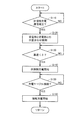
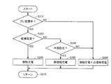
- FIG. 10 is a flowchart illustrating a power control processing procedure at the end of charging, which is executed by an ECU according to Embodiment 3.
- FIG. 10 is a functional block diagram of a portion related to charge control of an ECU in a fourth embodiment.
- 10 is a flowchart illustrating power control during pre-air conditioning executed by an ECU in the fourth embodiment.
- FIG. 1 is an overall configuration diagram of a vehicle charging system according to Embodiment 1 of the present invention.
- the vehicle charging system includes a vehicle 10 and a power supply facility 100.
- Vehicle 10 includes a power storage device 12, a system main relay (hereinafter referred to as “SMR (System Main Relay)”) 15, a power control unit (hereinafter referred to as “PCU (Power Control Unit)”) 20, and power.
- SMR System Main Relay
- PCU Power Control Unit
- the power storage device 12 is a rechargeable DC power source, and is constituted by a secondary battery such as nickel hydride or lithium ion, for example.
- the power storage device 12 stores power generated by the power output device 25 in addition to power supplied from external power supplies 110 and 130 (described later) of the power supply facility 100. Note that a large-capacity capacitor can also be employed as the power storage device 12.
- SMR 15 is provided between power storage device 12 and positive electrode line PL1, negative electrode line NL1.
- SMR 15 is a relay for electrically connecting / disconnecting power storage device 12 to positive electrode line PL1 and negative electrode line NL1.
- the PCU 20 collectively represents a power conversion device that receives power from the power storage device 12 and drives the power output device 25.
- PCU 20 includes an inverter for driving a motor included in power output device 25, a converter for boosting electric power output from power storage device 12, and the like.
- the power output device 25 is a general view of devices for driving the drive wheels 30.
- the power output device 25 includes a motor and an engine that drive the drive wheels 30.
- the power output device 25 generates power when the vehicle is braked by a motor that drives the drive wheels 30 and outputs the generated power to the PCU 20.
- the vehicle 10 further includes a charging inlet 40, a charger 45, and a first charging relay 50.
- the charging inlet 40 is configured to be connectable to a charging cable connector 120 that supplies electric power from the external power supply 110 of the power supply facility 100 to the vehicle 10.
- Charging inlet 40 receives power supplied from external power supply 110 via a charging cable when power storage device 12 is charged by external power supply 110.
- charging of the power storage device 12 by the external power source 110 using the charging cable is also referred to as “contact charging”.
- the charger 45 is connected to the positive line PL1 and the negative line NL1 disposed between the SMR 15 and the PCU 20 via the first charging relay 50.
- the charger 45 converts the power supplied from the external power supply 110 into the charging power of the power storage device 12 based on a control signal from the ECU 90 (described later). Then, the electric power output from the charger 45 is supplied to the power storage device 12 and the power storage device 12 is charged.
- First charging relay 50 is provided between charger 45 and positive electrode line PL1, negative electrode line NL1, and performs electrical connection / disconnection between charger 45 and positive electrode line PL1, negative electrode line NL1.
- the vehicle 10 further includes a power receiving unit 70, a rectifier 75, a sensor unit 80, a second charging relay 85, an electronic control device (hereinafter referred to as “ECU (Electronic Control Unit)”) 90, and first communication.
- ECU Electronic Control Unit
- a device 60 and a second communication device 95 are included.
- the power receiving unit 70 receives the AC power output from the power transmission unit 140 (described later) of the power supply facility 100 in a contactless manner when the power storage device 12 is charged by the external power source 130 of the power supply facility 100.
- charging of the power storage device 12 by the external power source 130 using the power receiving unit 70 and the power transmission unit 140 is also referred to as “non-contact charging”.
- the rectifier 75 rectifies the AC power received by the power receiving unit 70.
- the sensor unit 80 detects the power reception voltage and power reception current output from the rectifier 75 and outputs them to the ECU 90.
- the sensor unit 80 has a constant impedance on the vehicle 10 side when performing adjustment control such as alignment and impedance matching between the power receiving unit 70 and the power transmission unit 140 of the power supply facility 100, which is performed prior to non-contact charging.
- An adjustment resistor is provided for the purpose.
- Second charging relay 85 is provided between sensor unit 80 and positive electrode line PL1, negative electrode line NL1, and electrically connects / disconnects sensor unit 80 with positive electrode line PL1 and negative electrode line NL1.
- the configurations of the power reception unit 70 and the sensor unit 80 will be described later together with the configurations of the power transmission unit 140 and the matching unit 135 on the power supply facility 100 side and non-contact power transmission from the power transmission unit 140 to the power reception unit 70.
- the ECU 90 controls contact charging and non-contact charging by software processing by executing a program stored in advance by a CPU (Central Processing Unit) and / or hardware processing by a dedicated electronic circuit.
- a CPU Central Processing Unit
- the ECU 90 performs an on / off operation of the circuit breaker included in the first charging relay 50 and the EVSE (Electric Vehicle Supply Equipment) 115 of the power supply facility 100 when the contact charging is performed.
- EVSE 115 ECU 90 remotely operates EVSE 115 by operating the potential of pilot signal CPLT received from EVSE 115 via the control pilot line of the charging cable. Then, the ECU 90 generates a start / stop command for the charger 45, a power command indicating a target value of charging power by contact charging, and the like, and outputs the command to the charger 45.
- the ECU 90 executes adjustment control such as alignment and impedance matching between the power reception unit 70 and the power transmission unit 140 of the power supply facility 100 prior to the execution of non-contact charging. Specifically, the ECU 90 outputs a command to the sensor unit 80 so that the adjustment resistor in the sensor unit 80 is connected to the circuit when the adjustment control for non-contact charging is executed. When the adjustment control ends, the ECU 90 outputs an ON command to the second charging relay 85. Thereby, non-contact charge is attained.
- adjustment control such as alignment and impedance matching between the power reception unit 70 and the power transmission unit 140 of the power supply facility 100 prior to the execution of non-contact charging.
- the ECU 90 performs power control during contact charging and non-contact charging so that the power received by the vehicle 10 does not exceed the power received from the power supply facility 100. Specifically, the ECU 90 performs contact charging and non-contact so that the sum of charging power by contact charging using the charger 45 and charging power by non-contact charging using the power receiving unit 70 does not exceed a predetermined limit. Control the charging power by contact charging.
- the predetermined limit is, for example, input possible power Win indicating power that can be input to power storage device 12.
- a predetermined limit may be set based on the power that can be received from the external power source. For example, the limit in the external power source (for example, when the power supply facility 100 is a house) Contract power) may be set as the predetermined limit. This power control will be described in detail later.
- the first communication device 60 is a communication interface for communicating information related to contact charging with the outside of the vehicle (the power supply facility 100).
- the first communication device 60 communicates with the power supply facility 100 via a charging cable (communication via such a charging cable is also referred to as “power line communication (PLC)”).
- PLC power line communication
- the first communication device 60 is connected to the control pilot line of the charging cable, and communicates with the power supply equipment 100 via the control pilot line.
- the second communication device 95 is a communication interface for communicating information related to non-contact charging with the outside of the vehicle (power feeding facility 100).
- the second communication device 95 communicates with the power supply facility 100 wirelessly. It is not always necessary to provide the first and second communication devices 60 and 95, and the first and second communication devices 60 and 95 are configured by one communication device to perform PLC or wireless communication. Also good.
- the power supply facility 100 includes an external power source 110, an EVSE 115, and a connector 120.
- the external power source 110 is constituted by, for example, a commercial power source, but is not limited to this, and various power sources can be applied.
- the EVSE 115 is configured to be able to cut off an electric circuit for supplying electric power from the external power source 110 to the vehicle 10.
- the EVSE 115 is provided in a charging cable for supplying electric power from the external power source 110 to the vehicle 10 or a charging stand for supplying electric power to the vehicle 10 via the charging cable.
- EVSE 115 generates pilot signal CPLT for exchanging predetermined information with vehicle 10 and outputs the pilot signal CPLT to vehicle 10 through the control pilot line.
- the potential of pilot signal CPLT is manipulated in ECU 90 of vehicle 10, and EVSE 115 switches connection / cutoff of the charging circuit based on the potential of pilot signal CPLT.
- the connector 120 is connected to a charging cable including a control pilot line, and is configured to be able to be fitted to the charging inlet 40 of the vehicle 10.
- the power supply facility 100 further includes an external power source 130, a matching unit 135, a power transmission unit 140, an ECU 145, a third communication device 125, and a fourth communication device 150.
- the external power source 130 generates AC power having a predetermined frequency.
- the external power supply 130 receives power from a commercial power supply and generates high-frequency AC power.
- the external power supplies 110 and 130 may be configured as one power supply facility.
- the matching unit 135 is provided between the external power source 130 and the power transmission unit 140 and is configured to be able to change the internal impedance.
- the matching unit 135 includes a variable capacitor and a coil, and the impedance can be changed by changing the capacitance of the variable capacitor.
- the impedance of the power supply facility 100 can be matched with the impedance of the vehicle 10 (impedance matching).
- the matching unit 135 can be omitted.
- the power transmission unit 140 receives supply of AC power from the external power source 130. Then, the power transmission unit 140 outputs electric power in a non-contact manner to the power reception unit 70 of the vehicle 10 via an electromagnetic field generated around the power transmission unit 140.
- the configurations of the power transmission unit 140 and the matching unit 135 will be described later together with the configurations of the power reception unit 70 and the sensor unit 80 on the vehicle 10 side and the non-contact power transmission from the power transmission unit 140 to the power reception unit 70.
- the third communication device 125 is a communication interface for communicating information related to contact charging with the vehicle 10.
- the third communication device 125 communicates with the vehicle 10 via the charging cable.
- the third communication device 125 is connected to the control pilot line of the charging cable, and communicates with the first communication device 60 of the vehicle 10 via the control pilot line.
- the fourth communication device 150 is a communication interface for communicating information related to contactless charging with the vehicle 10.
- the fourth communication device 150 communicates with the vehicle 10 wirelessly. It is not always necessary to provide the third and fourth communication devices 125 and 150.
- the third and fourth communication devices 125 and 150 are configured by one communication device to perform PLC or wireless communication. Also good.
- the ECU 145 controls the external power supply 130 and the matching unit 135 by software processing by executing a program stored in advance by the CPU and / or hardware processing by a dedicated electronic circuit. Specifically, ECU 145 controls external power supply 130 so as to output adjustment power that is smaller than the power for charging power storage device 12 when adjustment control is performed before execution of contactless charging.
- the matching unit 135 is controlled to perform impedance matching. When the adjustment control ends, ECU 145 controls external power supply 130 so as to output electric power for charging power storage device 12.
- contact charging using the charging inlet 40 and the charger 45 and non-contact charging using the power transmission unit 140 and the power receiving unit 70 are possible. Then, the charging power by contact charging and non-contact charging is controlled so that the sum of the charging power by contact charging and the charging power by non-contact charging does not exceed the input possible power Win of power storage device 12.
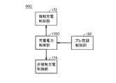
- FIG. 2 is a functional block diagram of a portion related to charging control of the ECU 90 mounted on the vehicle 10 shown in FIG.
- ECU 90 includes a charging power control unit 170, a contact charging control unit 172, and a non-contact charging control unit 174.
- the charging power control unit 170 controls charging power by contact charging and charging power by non-contact charging. Specifically, the charging power control unit 170 controls the charging powers Pc and Pw so that the sum of the charging power Pc by contact charging and the charging power Pw by non-contact charging does not exceed the input allowable power Win of the power storage device 12. To do.
- FIG. 3 is a diagram showing the input allowable power Win of the power storage device 12.
- outputtable power Wout indicating the power that can be output from power storage device 12 is also shown.
- the horizontal axis indicates the state of charge of power storage device 12 (hereinafter referred to as “SOC (State Of Charge)” and is expressed as a percentage (%) with respect to the capacity of power storage device 12).
- SOC State Of Charge
- the input allowable power Win is reduced in order to prevent the power storage device 12 from being overcharged.
- outputable power Wout is reduced in order to prevent overdischarge of power storage device 12.
- the input allowable power Win and the output allowable power Wout also vary depending on the temperature of the power storage device 12 and the like. Then, the charging powers Pc and Pw are controlled so that the sum of the charging power Pc by contact charging and the charging power Pw by non-contact charging does not exceed the input allowable power Win.
- charging power control unit 170 sets maximum power Pc_max indicating the upper limit of charging power Pc by contact charging and maximum power Pw_max indicating the upper limit of charging power Pw by non-contact charging. The value obtained by summing is compared with the input allowable power Win of power storage device 12. Information on the maximum powers Pc_max and Pw_max is obtained from the power supply facility 100 using the first communication device 60 and the second communication device 95. When the total value of the maximum powers Pc_max and Pw_max is equal to or less than the input allowable power Win, the charging power control unit 170 outputs a power command to the contact charging control unit 172 so that the charging power Pc matches the maximum power Pc_max. Then, a power command is output to the non-contact charging control unit 174 so that the charging power Pw matches the maximum power Pw_max.
- the charging power control unit 170 limits the receiving power of the less efficient of the contact charging and the non-contact charging to charge power.
- the charging powers Pc and Pw are controlled so that the sum of Pc and charging power Pw does not exceed the input allowable power Win.
- Various indexes can be used for the above “efficiency”, for example, efficiency from the viewpoint of cost (power cost), efficiency from the viewpoint of power transmission (power transmission efficiency), and power generation
- the “efficiency” of contact charging and non-contact charging can be compared based on the efficiency (CO2 amount) seen from the amount of carbon dioxide (CO2) discharged. It should be noted that restricting the inefficient one includes both reducing (limiting) the charging power of the inefficient and stopping the inefficient charging.
- the contact charge control unit 172 generates a drive signal for driving the charger 45 based on the power command received from the charge power control unit 170, and outputs the generated drive signal to the charger 45.
- the non-contact charge control unit 174 generates a signal for controlling the output power of the external power supply 130 (FIG. 1) based on the power command received from the charge power control unit 170, and uses the generated signal as the second communication. This is transmitted to the power supply facility 100 by the device 95.
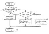
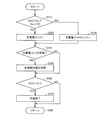
- FIG. 4 is a flowchart for explaining a power control processing procedure executed by the ECU 90. Note that the processing of this flowchart is called from the main routine and executed repeatedly at regular time intervals or whenever a predetermined condition is satisfied.
- ECU 90 determines that the sum of the maximum power Pw_max indicating the upper limit of charging power Pw by contactless charging and the maximum power Pc_max indicating the upper limit of charging power Pc by contact charging is the input permission of power storage device 12. It is determined whether or not the power is less than or equal to power Win (step S10).
- step S10 If it is determined in step S10 that the sum of the maximum powers Pw_max and Pc_max is equal to or less than the input allowable power Win (YES in step S10), the ECU 90 charges so that the charging power Pw by non-contact charging matches the maximum power Pw_max.
- the power Pw is controlled, and the charging power Pc is controlled so that the charging power Pc by contact charging matches the maximum power Pc_max (step S20).
- step S10 If it is determined in step S10 that the sum of the maximum powers Pw_max and Pc_max is larger than the input allowable power Win (NO in step S10), the ECU 90 has the power cost Cpw for non-contact charging lower than the power cost Cpc for contact charging. Is determined (step S30). Information on the power costs Cpw and Cpc is obtained from the power supply facility 100 using the first communication device 60 and the second communication device 95.
- step S30 If it is determined in step S30 that the power cost Cpw for contactless charging is lower than the power cost Cpc for contact charging (YES in step S30), the ECU 90 limits power reception by contact charging with a high power cost. For example, the ECU 90 controls the charging power Pw so that the charging power Pw matches the maximum power Pw_max for the charging power Pw by non-contact charging, and the input allowable power of the power storage device 12 for the charging power Pc by contact charging. The charging power Pc is controlled so as to coincide with the value obtained by subtracting the maximum power Pw_max of non-contact charging from Win (step S40).
- ECU 90 limits power reception by contactless charging with high power cost. .
- ECU 90 controls charging power Pw so that charging power Pw by non-contact charging matches a value obtained by subtracting maximum power Pc_max of contact charging from input allowable power Win of power storage device 12, and charging by contact charging.
- the charging power Pc is controlled so that the charging power Pc matches the maximum power Pc_max (step S50).
- FIG. 5 is a circuit diagram of the charger 45 and the EVSE 115 for performing contact charging. Note that the configuration shown in FIG. 5 is an example, and the configuration for performing contact charging is not limited to the configuration in FIG. 5.
- charger 45 includes an AC / DC converter 210, a DC / AC converter 215, an insulating transformer 220, and a rectifier 225.
- the AC / DC converter 210 converts AC power supplied from the external power supply 110 into DC power based on a control signal from the ECU 90, and outputs the DC power to the DC / AC converter 215.
- the AC / DC conversion unit 210 forms a boost chopper circuit together with a reactor provided on the input side of the AC / DC conversion unit 210, and can boost the power input from the charging inlet 40.
- DC / AC converter 215 converts the DC power received from AC / DC converter 210 into AC power based on a control signal from ECU 90 and outputs the AC power to insulating transformer 220.
- the DC / AC conversion unit 215 is configured by, for example, a single-phase bridge circuit.
- the insulating transformer 220 includes a core made of a magnetic material, and a primary coil and a secondary coil wound around the core.
- the primary coil and the secondary coil are electrically insulated and connected to the DC / AC converter 215 and the rectifier 225, respectively.
- Insulation transformer 220 converts AC power from DC / AC converter 215 into a voltage corresponding to the turn ratio of the primary coil and the secondary coil, and outputs the voltage to rectifier 225.
- the rectifying unit 225 converts AC power received from the insulating transformer 220 into DC power and outputs the DC power to the first charging relay 50.
- the AC / DC converter 210 and the rectifier 225 may be configured by a single-phase bridge circuit capable of bidirectional power conversion. Thereby, it is also possible to output electric power from the vehicle 10 to the outside of the vehicle.
- the EVSE 115 includes a CCID (Charging Circuit Interrupt Device) 235 and a CPLT control device 240.
- CCID 235 is a circuit breaker provided in a power supply path from external power supply 110 to vehicle 10, and is controlled by CPLT control device 240.
- the CPLT control device 240 generates a pilot signal CPLT for exchanging predetermined information between the EVSE 115 and the vehicle 10 during contact charging, and outputs the pilot signal CPLT to the vehicle 10 via the control pilot line.
- pilot signal CPLT The electric potential of pilot signal CPLT is manipulated in ECU 90 of vehicle 10, and CPLT control device 240 controls CCID 235 based on the electric potential of pilot signal CPLT. That is, the CCID 235 can be remotely operated from the vehicle 10 by operating the potential of the pilot signal CPLT in the vehicle 10.
- the pilot signal CPLT conforms to, for example, “SAE J1772 (SAE Electric Vehicle Conductive Charge Coupler)” in the United States.
- the first communication device 60 of the vehicle 10 is connected to the control pilot line through which the pilot signal CPLT is exchanged on the vehicle 10 side, and the third communication device 125 of the power supply facility 100 is connected to the control pilot line on the power supply facility 100 side. Connected to. Thereby, at the time of contact charging, information about contact charging (for example, information about maximum power Pc_max of contact charging, etc.) between the first communication device 60 and the third communication device 125 via the charging cable (control pilot line). Are communicated.
- FIG. 6 is a circuit diagram of the power reception unit 70 and the sensor unit 80, and the matching unit 135 and the power transmission unit 140 for performing non-contact charging. Note that the configuration shown in FIG. 6 is also an example, and the configuration for performing non-contact charging is not limited to the configuration in FIG. Referring to FIG. 6, power receiving unit 70 includes a coil 340 and a capacitor 350.
- the coil 340 forms a resonance circuit together with the capacitor 350, and receives the electric power sent from the power transmission unit 140 in a non-contact manner.
- Rectifier 75 rectifies the AC power received by coil 340 and outputs the rectified power to power lines L5 and L6.
- a closed loop may be formed by the coil 340 and the capacitor 350, and a coil for taking out AC power received by the coil 340 from the coil 340 by electromagnetic induction and outputting it to the rectifier 75 may be separately provided.
- Sensor unit 80 includes a relay 355, an adjustment resistor 360, voltage sensors 365 and 370, and a current sensor 375.
- Relay 355 and adjustment resistor 360 are connected in series between power lines L5 and L6. Relay 355 is turned on (conducted) when adjustment control is performed prior to contactless charging. Thereby, the impedance on the vehicle 10 side during the adjustment control becomes constant, and the adjustment control can be efficiently performed.
- the voltage sensor 365 detects the voltage of the adjustment resistor 360 and outputs it to the ECU 90.
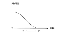
- Voltage sensor 370 detects the voltage between power lines L5 and L6, that is, the charging voltage of power storage device 12 during non-contact charging, and outputs the detected value to ECU 90.
- Current sensor 375 detects the current flowing through power line L5 (or power line L6), that is, the charging current of power storage device 12 during non-contact charging, and outputs the detected value to ECU 90.
- the matching unit 135 of the power supply facility 100 includes variable capacitors 310 and 315 and a coil 320.
- the matching unit 135 can change the impedance by changing the capacitance of the variable capacitors 310 and 315.
- the impedance of the power supply facility 100 can be matched with the impedance of the vehicle 10 (impedance matching).
- the matching unit 135 can be omitted.
- the power transmission unit 140 includes a coil 330 and a capacitor 335.
- the coil 330 forms a resonance circuit together with the capacitor 335 and transmits AC power supplied from the external power source 130 to the power receiving unit 70 of the vehicle 10 in a non-contact manner.
- a coil that forms a closed loop with the coil 330 and the capacitor 335 and supplies AC power output from the external power supply 130 to the coil 330 by electromagnetic induction may be provided separately.
- Capacitors 335 and 350 are provided to adjust the natural frequency of the resonance circuit. When a desired natural frequency is obtained by using the stray capacitance of coils 330 and 340, capacitors 335 and 350 are provided. It is good also as a structure which does not provide.
- the difference between the natural frequency of power transmission unit 140 and the natural frequency of power reception unit 70 is ⁇ 10% or less of the natural frequency of power transmission unit 140 or the natural frequency of power reception unit 70.
- the power transmission efficiency can be increased.
- the difference between the natural frequencies is larger than ⁇ 10%, the power transmission efficiency is smaller than 10%, and the power transmission time becomes longer.
- the natural frequency of the power receiving unit 70 means a vibration frequency when the electric circuit (resonance circuit) constituting the power reception unit 70 (power transmission unit 140) freely vibrates.
- the resonance frequency of the power reception unit 70 (power transmission unit 140) means a natural frequency when the braking force or the electrical resistance is zero in the electric circuit (resonance circuit) constituting the power reception unit 70 (power transmission unit 140). To do.
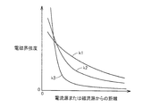
- FIG. 7 is a diagram illustrating a simulation model of the power transmission system.
- FIG. 8 is a diagram illustrating the relationship between the deviation of the natural frequencies of the power transmission unit and the power reception unit and the power transmission efficiency.
- the power transmission system 389 includes a power transmission unit 390 and a power reception unit 391.
- the power transmission unit 390 includes a first coil 392 and a second coil 393.
- the second coil 393 includes a resonance coil 394 and a capacitor 395 provided in the resonance coil 394.
- the power receiving unit 391 includes a third coil 396 and a fourth coil 397.
- the third coil 396 includes a resonance coil 399 and a capacitor 398 connected to the resonance coil 399.
- the inductance of the resonance coil 394 is the inductance Lt
- the capacitance of the capacitor 395 is the capacitance C1.
- the inductance of the resonance coil 399 is defined as an inductance Lr
- the capacitance of the capacitor 398 is defined as a capacitance C2.
- the horizontal axis indicates the deviation (%) of the natural frequency
- the vertical axis indicates the power transmission efficiency (%) at a constant frequency.
- the deviation (%) in natural frequency is expressed by the following equation (3).
- the power transmission efficiency can be increased to a practical level by setting. Furthermore, when the natural frequency of the second coil 393 and the third coil 396 is set so that the absolute value of the deviation (%) of the natural frequency is 5% or less of the natural frequency of the third coil 396, the power transmission efficiency is further increased. This is more preferable.
- the simulation software employs electromagnetic field analysis software (JMAG (registered trademark): manufactured by JSOL Corporation).
- the power receiving unit 70 of the vehicle 10 and the power transmission unit 140 of the power supply facility 100 are contactlessly powered through at least one of a magnetic field and an electric field formed between the power receiving unit 70 and the power transmission unit 140. Give and receive. Magnetic and electric fields vibrate at specific frequencies.
- the coupling coefficient ⁇ between the power receiving unit 70 and the power transmitting unit 140 is about 0.1 to 0.3, and preferably 0.1 or less. Then, power is transmitted from the power transmission unit 140 to the power reception unit 70 by causing the power reception unit 70 and the power transmission unit 140 to resonate with each other by an electromagnetic field.
- the “magnetic field of a specific frequency” typically has a relationship with the power transmission efficiency and the frequency of the current supplied to the power transmission unit 140.
- the power transmission efficiency when power is transmitted from the power transmission unit 140 to the power reception unit 70 varies depending on various factors such as the distance between the power transmission unit 140 and the power reception unit 70.
- the natural frequency (resonance frequency) of the power transmission unit 140 and the power reception unit 70 is f0
- the frequency of the current supplied to the power transmission unit 140 is f3
- the air gap between the power transmission unit 140 and the power reception unit 70 is the air gap AG.
- FIG. 9 is a graph showing the relationship between the power transmission efficiency when the air gap AG is changed and the frequency f3 of the current supplied to the power transmission unit 140 with the natural frequency f0 fixed.
- the horizontal axis indicates the frequency f3 of the current supplied to the power transmission unit 140
- the vertical axis indicates the power transmission efficiency (%).
- the efficiency curve L1 schematically shows the relationship between the power transmission efficiency when the air gap AG is small and the frequency f3 of the current supplied to the power transmission unit 140. As shown in the efficiency curve L1, when the air gap AG is small, the peak of power transmission efficiency occurs at frequencies f4 and f5 (f4 ⁇ f5).
- the two peaks when the power transmission efficiency is increased change so as to approach each other.
- the efficiency curve L2 when the air gap AG is larger than the predetermined distance, the power transmission efficiency has one peak, and the power transmission efficiency is obtained when the frequency of the current supplied to the power transmission unit 140 is the frequency f6. Becomes a peak.
- the efficiency curve L3 When the air gap AG is further increased from the state of the efficiency curve L2, the peak of power transmission efficiency is reduced as shown by the efficiency curve L3.
- the capacitance of the capacitors 335 and 350 is changed between the power transmission unit 140 and the power reception unit 70 by keeping the frequency of the current supplied to the power transmission unit 140 constant according to the air gap AG.
- a method of changing the characteristics of the power transmission efficiency in the network is conceivable. Specifically, the capacitances of the capacitors 335 and 350 are adjusted so that the power transmission efficiency reaches a peak in a state where the frequency of the current supplied to the power transmission unit 140 is constant. In this method, the frequency of the current flowing through the power transmission unit 140 and the power reception unit 70 is constant regardless of the size of the air gap AG.
- a method of changing the characteristics of the power transmission efficiency a method of using the matching unit 135 of the power supply facility 100, a method of using a converter provided between the rectifier 75 and the power storage device 12 in the vehicle 10, or the like is adopted. It is also possible to do.
- the second method is a method of adjusting the frequency of the current supplied to the power transmission unit 140 based on the size of the air gap AG.
- the power transmission characteristic is the efficiency curve L1
- a current having a frequency f4 or f5 is supplied to the power transmission unit 140.
- the frequency characteristics are the efficiency curves L2 and L3
- the current having the frequency f6 is supplied to the power transmission unit 140.
- the frequency of the current flowing through power transmission unit 140 and power reception unit 70 is changed in accordance with the size of air gap AG.
- the frequency of the current flowing through the power transmission unit 140 is a fixed constant frequency
- the frequency flowing through the power transmission unit 140 is a frequency that changes as appropriate depending on the air gap AG.
- a current having a specific frequency set so as to increase the power transmission efficiency is supplied to the power transmission unit 140 by the first method, the second method, or the like.
- a magnetic field electromagnettic field
- the power receiving unit 70 receives power from the power transmitting unit 140 through a magnetic field that is formed between the power receiving unit 70 and the power transmitting unit 140 and vibrates at a specific frequency.
- the “magnetic field oscillating at a specific frequency” is not necessarily a magnetic field having a fixed frequency.
- the frequency of the current supplied to the power transmission unit 140 is set, but the power transmission efficiency is the horizontal direction of the power transmission unit 140 and the power reception unit 70.
- the frequency changes depending on other factors such as a deviation, and the frequency of the current supplied to the power transmission unit 140 may be adjusted based on the other factors.
- FIG. 10 is a diagram showing the relationship between the distance from the current source or magnetic current source and the strength of the electromagnetic field.
- the electromagnetic field is composed of three components.
- the curve k1 is a component that is inversely proportional to the distance from the wave source, and is referred to as a “radiated electromagnetic field”.
- a curve k2 is a component inversely proportional to the square of the distance from the wave source, and is referred to as an “induction electromagnetic field”.
- the curve k3 is a component inversely proportional to the cube of the distance from the wave source, and is referred to as an “electrostatic magnetic field”.
- the wavelength of the electromagnetic field is “ ⁇ ”
- the distance at which the strengths of “radiation electromagnetic field”, “induction electromagnetic field”, and “electrostatic magnetic field” are substantially equal can be expressed as ⁇ / 2 ⁇ .
- the “electrostatic magnetic field” is a region where the intensity of the electromagnetic wave suddenly decreases with the distance from the wave source.
- this “electrostatic magnetic field” is a dominant near field (evanescent). (Energy) is used to transmit energy (electric power).
- the power transmitting unit 140 and the power receiving unit 70 for example, a pair of resonance coils having adjacent natural frequencies are resonated, whereby the other power receiving unit 70 is transmitted from the power transmitting unit 140.
- the resonance method Transmit energy (electric power) to Since this "electrostatic magnetic field" does not propagate energy far away, the resonance method transmits power with less energy loss than electromagnetic waves that transmit energy (electric power) by "radiant electromagnetic field” that propagates energy far away. be able to.
- the coupling coefficient ⁇ between the power transmission unit 140 and the power reception unit 70 is about 0.1 to 0.3, and preferably 0.1 or less.
- the coupling coefficient ⁇ is not limited to such a value, and may take various values that improve power transmission.
- the coupling coefficient ⁇ between the power transmission unit and the power reception unit is close to 1.0.
- the coupling between the power transmission unit 140 and the power reception unit 70 in the power transmission is, for example, “magnetic resonance coupling”, “magnetic field (magnetic field) resonance coupling”, “electromagnetic field (electromagnetic field) resonance coupling”, “ Electric field (electric field) resonance coupling ".
- the “electromagnetic field (electromagnetic field) resonance coupling” means a coupling including any of “magnetic resonance coupling”, “magnetic field (magnetic field) resonance coupling”, and “electric field (electric field) resonance coupling”.
- the power transmission unit 140 and the power reception unit 70 are formed by coils as described above, the power transmission unit 140 and the power reception unit 70 are mainly coupled by a magnetic field (magnetic field), and are referred to as “magnetic resonance coupling” or “magnetic field”. (Magnetic field) resonance coupling "is formed. It is also possible to employ antennas such as meander lines for the power transmission unit 140 and the power reception unit 70. In this case, the power transmission unit 140 and the power reception unit 70 are mainly based on an electric field (electric field). The “electric field (electric field) resonance coupling” is formed.
- the charging power Pc, Pw is controlled based on the sum of the charging power Pc by contact charging and the charging power Pw by non-contact charging. More specifically, the total value of maximum power Pc_max indicating the upper limit of charging power Pc by contact charging and maximum power Pw_max indicating the upper limit of charging power Pw by non-contact charging is a predetermined limit (input allowable power Win of power storage device 12). In the following cases, the charging powers Pc and Pw are controlled so that the charging powers Pc and Pw coincide with the maximum powers Pc_max and Pw_max, respectively.
- the total value of the maximum powers Pc_max and Pw_max exceeds a predetermined limit
- the total of the charging powers Pc and Pw is limited by limiting the power receiving with the lower efficiency (power cost) of contact charging and non-contact charging.
- the charging power Pc, Pw is controlled so that the voltage does not exceed a predetermined limit. Therefore, according to the first embodiment, contact charging and non-contact charging are performed under appropriate conditions suitable for the user merit while suppressing excessive input to the power storage device 12 and excessive power reception from the external power source.
- the power storage device 12 can be charged separately.
- FIG. 11 is a flowchart for explaining a power control processing procedure in the first modification. The process of this flowchart is also called from the main routine and executed repeatedly at regular time intervals or whenever a predetermined condition is satisfied. Referring to FIG. 11, this flowchart includes step S32 instead of step S30 in the flowchart shown in FIG.
- step S10 determines that the power transmission efficiency Epw of non-contact charging is the power transmission efficiency of contact charging. It is determined whether it is higher than Epc (step S32).
- This power transmission efficiency is the power receiving efficiency based on the power received by the charging inlet 40 and the power receiving unit 70, the charging efficiency based on the power actually charged in the power storage device 12, and the power transmission efficiency based on the reflected power on the power supply facility 100 side It is a broad concept including etc.
- step S32 If it is determined in step S32 that the power transmission efficiency Epw of contactless charging is higher than the power transmission efficiency Epc of contact charging (YES in step S32), the process proceeds to step S40, and the power transmission efficiency is relative. Therefore, the charging power Pc due to the low contact charging is limited.
- step S32 when it is determined in step S32 that the power transmission efficiency Epw of contactless charging is equal to or less than the power transmission efficiency Epc of contact charging (NO in step S32), the process proceeds to step S50, and the power transmission efficiency is relative. Therefore, the charging power Pw due to the low non-contact charging is limited.
- FIG. 12 is a flowchart for explaining a power control processing procedure in the second modification. The process of this flowchart is also called from the main routine and executed repeatedly at regular time intervals or whenever a predetermined condition is satisfied. Referring to FIG. 12, this flowchart includes step S34 instead of step S30 in the flowchart shown in FIG.
- the ECU 90 determines that the carbon dioxide amount CO2pw for non-contact charging is the carbon dioxide amount for contact charging. It is determined whether it is less than CO2pc (step S34).
- the carbon dioxide amount CO2pw is calculated by multiplying the CO2 emission amount per unit power of the external power source 130 (FIG. 1) and the power transmission efficiency of non-contact charging
- the carbon dioxide amount CO2pc is calculated from the external power source 110 ( It is calculated by multiplying the CO2 emission amount per unit power of FIG. 1) and the power transmission efficiency of contact charging.
- Information on the carbon dioxide amounts CO2pw and CO2pc is obtained from the power supply facility 100 using the first communication device 60 and the second communication device 95.
- step S34 If it is determined in step S34 that the carbon dioxide amount CO2pw for non-contact charging is smaller than the carbon dioxide amount CO2pc for contact charging (YES in step S34), the process proceeds to step S40, and the carbon dioxide amount is relatively Charging power Pc due to a large amount of contact charging is limited. On the other hand, if it is determined in step S34 that the carbon dioxide amount CO2pw for non-contact charging is equal to or greater than the carbon dioxide amount CO2pc for contact charging (NO in step S34), the process proceeds to step S50, and the carbon dioxide amount is relative. Charging power Pw due to a large amount of non-contact charging is limited.
- the vehicle 10 For contact charging using the charging inlet 40 and the charger 45, the vehicle 10 is guided to a position where power can be supplied to the vehicle 10 from the power supply facility 100 by the charging cable, and then the charging cable is connected to the charging inlet 40. To start charging.
- the vehicle 10 for non-contact charging, if the vehicle 10 is guided to a position where power can be transmitted from the power transmission unit 140 of the power supply facility 100 to the power receiving unit 70 of the vehicle 10, charging is performed without connecting a cable as in the case of contact charging. Can start.
- contactless charging is started before contact charging. That is, when the vehicle 10 is guided to a position where power can be transmitted from the power transmission unit 140 of the power supply facility 100 to the power reception unit 70 of the vehicle 10 (hereinafter, such guidance control is performed as “position between the power reception unit 70 and the power transmission unit 140. Also referred to as “matching control”), non-contact charging is started. Thereafter, when the charging cable is connected to the charging inlet 40, contact charging is started.
- the overall configuration diagram of the vehicle charging system according to the second embodiment is the same as the configuration of the first embodiment shown in FIG.
- FIG. 13 is a functional block diagram of a part related to charge control of the ECU 90A in the second embodiment.
- ECU 90 ⁇ / b> A further includes an alignment control unit 176 in the configuration of ECU 90 in the first embodiment shown in FIG. 2, and includes a charging power control unit 170 ⁇ / b> A instead of charging power control unit 170.
- the alignment control unit 176 controls alignment between the power transmission unit 140 and the power reception unit 70 so that power transmission from the power transmission unit 140 of the power supply facility 100 to the power reception unit 70 of the vehicle 10 is performed with appropriate efficiency. Specifically, for a certain primary side voltage (output voltage from the power supply facility 100) as shown in FIG. 14, the secondary side voltage (received voltage of the vehicle 10) is transmitted as shown in FIG. It changes according to the distance L between the unit 140 and the power receiving unit 70. Therefore, a map or the like is created by measuring the relationship between the primary side voltage and the secondary side voltage shown in FIGS. 14 and 15 in advance, and the detected value of the secondary side voltage (the received voltage of the vehicle 10) is obtained. Based on this, it is possible to detect the distance between the power transmission unit 140 and the power reception unit 70.
- the received power or the receiving efficiency of the vehicle 10 may be used instead of the received voltage of the vehicle 10.
- the primary current output current from the power supply facility 100
- the output current from the power supply facility 100 is detected using this relationship.
- the distance between the power transmission unit 140 and the power reception unit 70 may be detected based on the value.
- the alignment control unit 176 notifies the charging power control unit 170A to that effect.
- the determination of completion of preparation for non-contact charge includes the operation of the parking brake, the transition to the Ready-OFF state indicating the stop of the vehicle system, and the non-contact charge start switch provided for exclusive use. An on operation or the like may be used.
- the charging power control unit 170A When receiving the above notification from the alignment control unit 176, the charging power control unit 170A instructs the non-contact charging control unit 174 to start non-contact charging. After that, when a charging cable is connected to the charging inlet 40 and preparation for contact charging is completed, the charging power control unit 170A instructs the contact charging control unit 172 to start contact charging. In addition, as a determination of the completion of preparation for contact charging, in addition to connection of a charging cable, an on operation of a dedicated contact charging start switch may be used. Control of charging power Pw by non-contact charging and charging power Pc by contact charging is the same as charging power control unit 170 in the first embodiment.
- FIG. 16 is a flowchart for explaining a control processing procedure at the start of charging executed by the ECU 90A according to the second embodiment. The process of this flowchart is also called from the main routine and executed repeatedly at regular time intervals or whenever a predetermined condition is satisfied.
- ECU 90A determines whether or not communication related to non-contact charging has been established (step S110). Note that communication related to non-contact charging is performed wirelessly between the second communication device 95 of the vehicle 10 and the fourth communication device 150 of the power supply facility 100, and here, the second communication device 95 and the fourth communication device are here. It is determined whether or not communication with 150 has been established.
- ECU 90A executes alignment control between power reception unit 70 of vehicle 10 and power transmission unit 140 of power supply facility 100 (step S120).
- the ECU 90A determines whether or not the vehicle speed of the vehicle 10 is lower than the value ⁇ (step S130).
- the value ⁇ is a threshold value for determining whether the vehicle 10 is stopped.
- ECU 90A starts non-contact charging (step S140).
- the ECU 90A determines whether or not a charging cable for contact charging is connected to the charging inlet 40 (step S150). Then, the connection of the charging cable is determined (YES in step S150). After that, when preparation for contact charging is completed, ECU 90A starts contact charging using charger 45 (step S160).
- the contact charging is performed. Non-contact charging is started first without waiting for preparation (connection of a charging cable, etc.). Therefore, according to the second embodiment, the charging of power storage device 12 by the external power supply can be terminated quickly.
- FIG. 17 is a diagram showing an example of changes in charging power Pchg and SOC of power storage device 12 during full charge control.
- P1 of charging power Pchg for example, input allowable power Win.
- P1 of charging power Pchg for example, input allowable power Win.
- FIG. 18 is a diagram showing the power transmission efficiency between contact charging and non-contact charging.
- the horizontal axis indicates charging power
- the vertical axis indicates power transmission efficiency.
- line L11 shows the efficiency curve of contact charging
- line L12 shows the efficiency curve of non-contact charging.
- the efficiency does not change so much depending on the magnitude of the charging power, but for non-contact charging, the impedance changes equivalently when the charging power is reduced, resulting in the power transfer efficiency. Decreases.
- the overall configuration diagram of the vehicle charging system according to the third embodiment is the same as the configuration of the first embodiment shown in FIG.
- FIG. 19 is a functional block diagram of a portion related to charging control of the ECU 90B according to the third embodiment.
- ECU 90B further includes an SOC calculation unit 178 and a full charge control unit 180 in the configuration of ECU 90 in the first embodiment shown in FIG.
- a power control unit 170B is included.
- the SOC calculation unit 178 calculates the SOC of the power storage device 12 based on the voltage and current of the power storage device 12 detected by a sensor (not shown). Various known methods can be used for calculating the SOC.
- the full charge control unit 180 receives the calculated value of the SOC from the SOC calculation unit 178. Then, when the SOC reaches the predetermined value Su immediately before full charge, the full charge control unit 180 notifies the charge power control unit 170B to that effect. Further, when the SOC reaches the full charge state Sf, the full charge control unit 180 notifies the charge power control unit 170B of that fact.
- the charging power control unit 170B is the sum of the charging power Pc by contact charging and the charging power Pw by contactless charging, similar to the charging power control unit 170 described in the first embodiment, until the SOC reaches a predetermined value Su.
- Charge electric power Pc, Pw is controlled so as not to exceed the input allowable electric power Win of power storage device 12.
- the charging power control unit 170B instructs the non-contact charging control unit 174 to stop the non-contact charging.
- the ratio of the contact charging may be relatively increased by reducing the charging power Pw by the non-contact charging without stopping the non-contact charging.
- FIG. 20 is a flowchart illustrating a power control processing procedure at the end of charging, which is executed by ECU 90B in the third embodiment. The process of this flowchart is also called from the main routine and executed repeatedly at regular time intervals or whenever a predetermined condition is satisfied.
- ECU 90B determines whether or not the SOC of power storage device 12 has exceeded a predetermined value Su immediately before full charge (step S210). If it is determined that the SOC has not reached predetermined value Su (NO in step S210), ECU 90B sets charging power Pchg of power storage device 12 to P1 (FIG. 17) (step S220). As described above, P1 is, for example, input allowable power Win. When SOC reaches predetermined value Su (YES in step S210), ECU 90B limits charging power Pchg of power storage device 12 to P2 (FIG. 17) (step S230).
- the ECU 90B determines whether or not the charging power Pchg is smaller than a predetermined value (step S240).
- This predetermined value is a threshold value for limiting contactless charging in order to suppress a decrease in power transmission efficiency due to a decrease in efficiency of contactless charging, and is set based on the efficiency curve shown in FIG. .
- step S250 If it is determined that charging power Pchg is smaller than the predetermined value (YES in step S240), ECU 90B limits non-contact charging (step S250). As described above, the ECU 90B may stop the non-contact charging, or may reduce the charging power Pw by the non-contact charging without stopping the non-contact charging. If it is determined in step S240 that charging power Pchg is greater than or equal to a predetermined value (NO in step S240), ECU 90B proceeds to step S260 without executing step S250.
- ECU 90B determines whether or not the SOC of power storage device 12 has exceeded full charge state Sf (step S260). When it is determined that the SOC has exceeded full charge state Sf (YES in step S260), ECU 90B ends the charging of power storage device 12 (step S270). If it is determined in step S260 that the SOC is equal to or lower than full charge state Sf (NO in step S260), ECU 90B proceeds to step S280 without executing step S270.
- the charging power Pchg is limited to the constant value P2 and the power storage device is charged (such charging is constant).
- constant voltage charging CV charging
- the charging power Pchg becomes smaller as the SOC approaches the fully charged state Sf.
- the non-contact charging is restricted, and the reduction in power transmission efficiency is suppressed.
- the SOC when the SOC reaches the predetermined value Su immediately before full charge, non-contact charge is limited, and the power storage device 12 is charged using contact charge. Thereby, the fall of the power transmission efficiency at the time of charge power restriction just before full charge is suppressed. Therefore, according to the third embodiment, power storage device 12 can be charged with higher efficiency.
- the fourth embodiment is configured such that pre-air conditioning for air-conditioning the passenger compartment in advance before boarding can be performed.
- Pre-air conditioning is performed using an electric air conditioner. Therefore, the charging power of the vehicle 10 decreases as the pre-air conditioning is performed.
- pre-air conditioning is required before using the vehicle 10 without removing the charging cable. And the like, the decrease in charging power due to pre-air conditioning can be supplemented from the power supply facility 100.
- the overall configuration diagram of the vehicle charging system according to the fourth embodiment is the same as the configuration of the first embodiment shown in FIG.
- FIG. 21 is a functional block diagram of a portion related to charging control of the ECU 90C according to the fourth embodiment.
- ECU 90 ⁇ / b> C further includes a pre-air-conditioning control unit 182 in the configuration of ECU 90 in the first embodiment shown in FIG. 2, and includes a charging power control unit 170 ⁇ / b> C instead of charging power control unit 170.
- the pre-air conditioning control unit 182 performs pre-air conditioning for heating or cooling when there is a request for performing pre-air conditioning.
- the setting of heating or cooling may be set by the user, or may be set according to the difference between the outside air temperature and the set temperature. Then, the pre-air conditioning control unit 182 notifies the charging power control unit 170C of the fact that the pre-air conditioning is performed and the setting of heating / cooling.
- the charging power control unit 170C When the pre-air conditioning for heating is performed, the charging power control unit 170C outputs a power command for compensating for a decrease in charging power due to the pre-air conditioning to the contact charging control unit 172.
- a power command corresponding to the power used for pre-air conditioning is output to contact charge control unit 172.
- a power command obtained by adding a power command for pre-air conditioning to a power command for contact charging is output to the contact charging control unit 172.
- charging power control unit 170C outputs a power command to compensate for a decrease in charging power due to pre-air conditioning to non-contact charging control unit 174.
- a power command corresponding to the power used for pre-air conditioning is output to contactless charging control unit 174.
- a power command obtained by adding the power command for pre-air conditioning to the power command for non-contact charging is output to the non-contact charging control unit 174.
- FIG. 22 is a flowchart illustrating power control during pre-air conditioning executed by ECU 90C in the fourth embodiment. The process of this flowchart is also called from the main routine and executed repeatedly at regular time intervals or whenever a predetermined condition is satisfied.
- ECU 90C determines whether or not pre-air conditioning is being performed (step S310). If it is determined that pre-air conditioning is being performed (YES in step S310), ECU 90C determines whether or not pre-air conditioning is heating setting (step S320). This setting may be set by the user or may be set according to the difference between the outside air temperature and the set temperature. If it is determined in step S320 that the heating setting is set (YES in step S320), ECU 90C compensates for a reduction in charging power due to pre-air conditioning by performing contact charging with relatively large heat generation (step S330). ).
- ECU 90C determines whether or not the pre-air conditioning is the cooling setting (step S340). This setting may also be set by the user or according to the difference between the outside air temperature and the set temperature. If it is determined in step S340 that the cooling setting is set (YES in step S340), ECU 90C compensates for a reduction in charging power due to pre-air conditioning by performing non-contact charging with relatively small heat generation (step S340). S350).
- step S310 If it is determined in step S310 that pre-air conditioning is not being performed (NO in step S310), or if it is determined in step S340 that the cooling setting is not being performed (NO in step S340), ECU 90C performs contact charging and non-contact charging. Power control is executed so as to charge the power storage device 12 using both (step S360).
- pre-air conditioning during pre-air conditioning with heating setting, contact charging with relatively large heat generation is executed in order to compensate for a decrease in charging power due to pre-air conditioning.
- fever accompanying contact charge can be anticipated.
- pre-air conditioning with a cooling setting non-contact charging with relatively small heat generation is performed in order to compensate for a decrease in charging power due to pre-air conditioning. Thereby, the cooling effect is not greatly inhibited. Therefore, according to the fourth embodiment, pre-air conditioning can be executed efficiently.
- each of the first to fourth embodiments can be combined with each other.
- each control executed by the ECUs 90 and 90A to 90C in the above first to fourth embodiments can be executed by the ECU 145 of the power supply facility 100.
- the vehicle 10 and the power supply facility 100 can transmit and receive information bidirectionally by wired communication using the first communication device 60 and the third communication device 125 and wireless communication using the second communication device 95 and the fourth communication device 150. Because it can.
- the inventions described in the above first to third embodiments can be applied to power receiving equipment other than vehicles.
- the present invention can be applied to portable information terminals and home appliances.
- power is transmitted from the power transmission unit 140 to the power reception unit 70 in a non-contact manner by causing the power transmission unit 140 of the power supply facility 100 and the power reception unit 70 of the vehicle 10 to resonate (resonate) with an electromagnetic field.
- electric power may be transmitted from the power transmitting unit 140 to the power receiving unit 70 in a non-contact manner by electromagnetic induction.
- the coupling coefficient ⁇ between the power transmission unit 140 and the power reception unit 70 is a value close to 1.0.
- charging inlet 40 and charger 45 form an example of “first power receiving unit” in the present invention
- power receiving unit 70 is an example of “second power receiving unit” in the present invention
- ECU 90 corresponds to an example of the “control unit” in the invention of the vehicle power receiving device.
- EVSE 115 and connector 120 form an example of “first power transmission unit” in the present invention
- power transmission unit 140 corresponds to an example of “second power transmission unit” in the present invention
- ECU 145 corresponds to an example of “control unit” in the invention of the power supply facility.
Landscapes
- Engineering & Computer Science (AREA)
- Power Engineering (AREA)
- Transportation (AREA)
- Mechanical Engineering (AREA)
- Computer Networks & Wireless Communication (AREA)
- Life Sciences & Earth Sciences (AREA)
- Sustainable Development (AREA)
- Sustainable Energy (AREA)
- Electric Propulsion And Braking For Vehicles (AREA)
- Charge And Discharge Circuits For Batteries Or The Like (AREA)
- Current-Collector Devices For Electrically Propelled Vehicles (AREA)
Abstract
Description
好ましくは、第1および第2の受電部の双方を用いた受電が要求された場合、制御部は、第1の受電部による受電よりも第2の受電部による受電を先に開始する。
図1は、この発明の実施の形態1による車両充電システムの全体構成図である。図1を参照して、車両充電システムは、車両10と、給電設備100とを備える。車両10は、蓄電装置12と、システムメインリレー(以下「SMR(System Main Relay)」と称する。)15と、パワーコントロールユニット(以下「PCU(Power Control Unit)」と称する。)20と、動力出力装置25と、駆動輪30とを含む。
f2=1/{2π(Lr×C2)1/2}・・・(2)
ここで、インダクタンスLrおよびキャパシタンスC1,C2を固定して、インダクタンスLtのみを変化させた場合において、第2コイル393および第3コイル396の固有周波数のズレと電力伝送効率との関係を図8に示す。なお、このシミュレーションにおいては、共振コイル394および共振コイル399の相対的な位置関係は固定とし、さらに、第2コイル393に供給される電流の周波数は一定である。
図8からも明らかなように、固有周波数のズレ(%)が0%の場合には、電力伝送効率は100%近くとなる。固有周波数のズレ(%)が±5%の場合には、電力伝送効率は40%程度となる。固有周波数のズレ(%)が±10%の場合には、電力伝送効率は10%程度となる。固有周波数のズレ(%)が±15%の場合には、電力伝送効率は5%程度となる。すなわち、固有周波数のズレ(%)の絶対値(固有周波数の差)が、第3コイル396の固有周波数の10%以下の範囲となるように第2コイル393および第3コイル396の固有周波数を設定することで、電力伝送効率を実用的なレベルに高めることができることがわかる。さらに、固有周波数のズレ(%)の絶対値が第3コイル396の固有周波数の5%以下となるように第2コイル393および第3コイル396の固有周波数を設定すると、電力伝送効率をさらに高めることができるのでより好ましい。なお、シミュレーションソフトしては、電磁界解析ソフトウェア(JMAG(登録商標):株式会社JSOL製)を採用している。
上記においては、接触充電による充電電力Pcの上限を示す最大電力Pc_maxと、非接触充電による充電電力Pwの上限を示す最大電力Pw_maxとの合計値が所定の制限を超える場合に、接触充電と非接触充電とのうち電力コストの悪い方の受電を制限するものとしたが、電力コストに代えて電力伝送効率を指標としてもよい。すなわち、この変形例1では、最大電力Pc_max,Pw_maxの合計が所定の制限を超える場合、接触充電と非接触充電とのうち電力伝送効率の悪い方の受電が制限される。なお、電力伝送効率の悪い方を制限するとは、電力伝送効率の悪い方の充電電力を絞る(制限する)ことと、電力伝送効率の悪い方の充電を停止することとの双方を含む。
[実施の形態1の変形例2]
変形例1では、最大電力Pc_max,Pw_maxの合計が所定の制限を超える場合、接触充電と非接触充電とのうち電力伝送効率の悪い方の受電を制限するものとしたが、電力伝送効率に代えて、電力生成に伴なうCO2量を指標としてもよい。
[実施の形態2]
充電インレット40および充電器45を用いた接触充電については、給電設備100から充電ケーブルによって車両10へ給電可能な位置に車両10を誘導して停車した後、充電ケーブルを充電インレット40に接続することによって充電が開始される。一方、非接触充電については、給電設備100の送電部140から車両10の受電部70へ送電可能な位置に車両10を誘導すれば、接触充電の場合のようなケーブルの接続を行なうことなく充電を開始することができる。
充電器45を用いた接触充電および受電部70を用いた非接触充電により、蓄電装置12は、所定の満充電状態(たとえばSOC80%)まで充電される。この実施の形態3では、外部電源により蓄電装置12を満充電状態に充電するための満充電制御が2段階に分けて実施される。
この実施の形態4では、乗車前に車室内を事前に空調するプレ空調を実施可能に構成される。プレ空調は、電動エアコンを用いて実施される。したがって、プレ空調の実施に伴ない車両10の充電電力は低下する。プレ空調時に給電設備100から車両10を充電可能な状態のとき(たとえば、外部電源による蓄電装置12の充電終了後、充電ケーブルが取外されることもなく車両10の利用前にプレ空調が要求された場合等)、プレ空調による充電電力の低下を給電設備100から補充することができる。
また、上記の実施の形態1~4においてECU90,90A~90Cにより実行される各制御は、給電設備100のECU145において実行することが可能である。車両10と給電設備100とは、第1通信装置60および第3通信装置125による有線通信、ならびに第2通信装置95および第4通信装置150による無線通信によって、双方向に情報を送受することができるからである。
Claims (28)
- 車両外部の電源から受電するための車両用受電装置であって、
前記電源から電力線を介して受電する第1の受電部(40,45)と、
前記電源から非接触で受電する第2の受電部(70)と、
前記車両が受電可能な電力を前記電源からの受電電力が超えないように、前記第1の受電部により受電される電力を示す第1の電力および前記第2の受電部により受電される電力を示す第2の電力を制御する制御部(90,90A~90C)とを備える車両用受電装置。 - 前記制御部は、前記第1の電力と前記第2の電力との合計に基づいて、前記第1の電力および前記第2の電力を制御する、請求項1に記載の車両用受電装置。
- 前記制御部は、前記第1および第2の電力の合計が所定の制限を超えないように前記第1および第2の電力を制御する、請求項2に記載の車両用受電装置。
- 前記第1の受電部によって受電可能な電力と前記第2の受電部によって受電可能な電力との合計が前記所定の制限以下のとき、前記制御部は、前記第1および第2の受電部の双方を用いて前記電源から受電するように前記第1および第2の電力を制御する、請求項3に記載の車両用受電装置。
- 前記第1の受電部によって受電可能な電力と前記第2の受電部によって受電可能な電力との合計が前記所定の制限を超えるとき、前記制御部は、前記第1の受電部による受電と前記第2の受電部による受電とのうち効率の悪い方の受電を制限するように前記第1および第2の電力を制御する、請求項3または4に記載の車両用受電装置。
- 前記第1および第2の電力によって充電される蓄電装置(12)をさらに備え、
前記所定の制限は、前記蓄電装置へ入力可能な電力を示す入力許容電力である、請求項3に記載の車両用受電装置。 - 前記所定の制限は、前記電源から受電可能な電力に基づいて設定される、請求項3に記載の車両用受電装置。
- 前記第1および第2の受電部の双方を用いた受電が要求された場合、前記制御部(90A)は、前記第1の受電部による受電よりも前記第2の受電部による受電を先に開始する、請求項1に記載の車両用受電装置。
- 前記第1および第2の受電部の双方を用いた受電が要求された場合、前記制御部(90A)は、前記第2の受電部による受電の準備完了後、前記第1の受電部による受電の準備完了前に、前記第2の受電部による受電を開始する、請求項1に記載の車両用受電装置。
- 前記第1および第2の電力によって充電される蓄電装置(12)をさらに備え、
前記制御部(90B)は、前記蓄電装置の充電状態が満充電状態に近づいたことを示す所定量に前記充電状態が達すると前記蓄電装置の充電電力を低減させる満充電制御を実行し、前記満充電制御の実行時、前記第2の受電部による受電を制限する、請求項1に記載の車両用受電装置。 - 利用者が前記車両を利用する前に車室内を空調するプレ空調を実施可能な電動空調装置をさらに備え、
前記制御部(90C)は、前記プレ空調の暖房時、前記第1の受電部による受電を実行する、請求項1に記載の車両用受電装置。 - 利用者が前記車両を利用する前に車室内を空調するプレ空調を実施可能な電動空調装置をさらに備え、
前記制御部(90C)は、前記プレ空調の冷房時、前記第2の受電部による受電を実行する、請求項1に記載の車両用受電装置。 - 前記電源は、前記第2の受電部へ非接触で送電する送電部(140)を含み、
前記第2の受電部の固有周波数と前記送電部の固有周波数との差は、前記第2の受電部の固有周波数または前記送電部の固有周波数の±10%以下である、請求項1に記載の車両用受電装置。 - 前記電源は、前記第2の受電部へ非接触で送電する送電部(140)を含み、
前記第2の受電部と前記送電部との結合係数は0.1以下である、請求項1に記載の車両用受電装置。 - 前記電源は、前記第2の受電部へ非接触で送電する送電部(140)を含み、
前記第2の受電部は、前記第2の受電部と前記送電部との間に形成される磁界と、前記第2の受電部と前記送電部との間に形成される電界との少なくとも一方を通じて、前記送電部から受電し、
前記磁界および前記電界は、前記第2の受電部と前記送電部との間に形成され、かつ、特定の周波数で振動する、請求項1に記載の車両用受電装置。 - 車両へ給電するための給電設備であって、
電力線を介して前記車両へ送電する第1の送電部(115,120)と、
前記車両へ非接触で送電する第2の送電部(140)と、
前記車両が受電可能な電力を前記車両への送電電力が超えないように、前記第1の送電部により送電される電力を示す第1の電力および前記第2の送電部により送電される電力を示す第2の電力を制御する制御部(145)とを備える給電設備。 - 前記制御部は、前記第1の電力と前記第2の電力との合計に基づいて、前記第1の電力および前記第2の電力を制御する、請求項16に記載の給電設備。
- 前記制御部は、前記第1および第2の電力の合計が所定の制限を超えないように前記第1および第2の電力を制御する、請求項17に記載の給電設備。
- 前記第1の送電部によって送電可能な電力と前記第2の送電部によって送電可能な電力との合計が前記所定の制限以下のとき、前記制御部は、前記第1および第2の送電部の双方を用いて前記車両へ送電するように前記第1および第2の電力を制御する、請求項18に記載の給電設備。
- 前記第1の送電部によって送電可能な電力と前記第2の送電部によって送電可能な電力との合計が前記所定の制限を超えるとき、前記制御部は、前記第1の送電部による送電と前記第2の送電部による送電とのうち効率の悪い方の送電を制限するように前記第1および第2の電力を制御する、請求項18または19に記載の給電設備。
- 前記第1および第2の送電部の双方を用いた送電が要求された場合、前記制御部は、前記第1の送電部による送電よりも前記第2の送電部による送電を先に開始する、請求項16に記載の給電設備。
- 前記第1および第2の送電部の双方を用いた送電が要求された場合、前記制御部は、前記第2の送電部による送電の準備完了後、前記第1の送電部による送電の準備完了前に、前記第2の送電部による送電を開始する、請求項16に記載の給電設備。
- 前記車両は、
前記第1および第2の電力によって充電される蓄電装置(12)と、
前記蓄電装置の充電状態が満充電状態に近づいたことを示す所定量に前記充電状態が達すると前記蓄電装置の充電電力を低減させる満充電制御を実行する満充電制御部(180)とを含み、
前記制御部は、前記満充電制御の実行時、前記第2の送電部による送電を制限する、請求項16に記載の給電設備。 - 前記車両は、前記第2の送電部から非接触で受電する受電部(70)を含み、
前記第2の送電部の固有周波数と前記受電部の固有周波数との差は、前記第2の送電部の固有周波数または前記受電部の固有周波数の±10%以下である、請求項16に記載の給電設備。 - 前記車両は、前記第2の送電部から非接触で受電する受電部(70)を含み、
前記第2の送電部と前記受電部との結合係数は0.1以下である、請求項16に記載の給電設備。 - 前記車両は、前記第2の送電部から非接触で受電する受電部(70)を含み、
前記第2の送電部は、前記第2の送電部と前記受電部との間に形成される磁界と、前記第2の送電部と前記受電部との間に形成される電界との少なくとも一方を通じて、前記受電部へ送電し、
前記磁界および前記電界は、前記第2の送電部と前記受電部との間に形成され、かつ、特定の周波数で振動する、請求項16に記載の給電設備。 - 給電設備から車両へ電力を伝送する電力伝送システムであって、
前記給電設備から電力線を介して前記車両へ電力を伝送する第1の送受電部(115,120,40,45)と、
前記給電設備から前記車両へ非接触で電力を伝送する第2の送受電部(140,70)と、
前記給電設備から前記車両へ伝送される電力が、前記車両が受電可能な電力を超えないように、前記第1の送受電部により伝送される電力を示す第1の電力および前記第2の送受電部により伝送される電力を示す第2の電力を制御する制御部(90,90A~90C,145)とを備える電力伝送システム。 - 前記制御部は、前記第1の電力と前記第2の電力との合計に基づいて、前記第1の電力および前記第2の電力を制御する、請求項27に記載の電力伝送システム。
Priority Applications (7)
| Application Number | Priority Date | Filing Date | Title |
|---|---|---|---|
| PCT/JP2012/051930 WO2013114522A1 (ja) | 2012-01-30 | 2012-01-30 | 車両用受電装置、給電設備、および電力伝送システム |
| KR1020147023339A KR20140117587A (ko) | 2012-01-30 | 2012-01-30 | 차량용 수전 장치, 급전 설비 및 전력 전송 시스템 |
| US14/374,308 US9533591B2 (en) | 2012-01-30 | 2012-01-30 | Vehicular power reception device, power supply apparatus, and electric power transfer system |
| CN201710071236.8A CN107089142B (zh) | 2012-01-30 | 2012-01-30 | 车辆用受电装置、供电设备以及电力传输系统 |
| CN201280068584.5A CN104105616B (zh) | 2012-01-30 | 2012-01-30 | 车辆用受电装置、供电设备以及电力传输系统 |
| EP12867094.0A EP2810814B1 (en) | 2012-01-30 | 2012-01-30 | Vehicle power receiving device, power supply equipment and electrical power transmission system |
| JP2013556066A JP6135513B2 (ja) | 2012-01-30 | 2012-01-30 | 車両用受電装置 |
Applications Claiming Priority (1)
| Application Number | Priority Date | Filing Date | Title |
|---|---|---|---|
| PCT/JP2012/051930 WO2013114522A1 (ja) | 2012-01-30 | 2012-01-30 | 車両用受電装置、給電設備、および電力伝送システム |
Publications (1)
| Publication Number | Publication Date |
|---|---|
| WO2013114522A1 true WO2013114522A1 (ja) | 2013-08-08 |
Family
ID=48904609
Family Applications (1)
| Application Number | Title | Priority Date | Filing Date |
|---|---|---|---|
| PCT/JP2012/051930 Ceased WO2013114522A1 (ja) | 2012-01-30 | 2012-01-30 | 車両用受電装置、給電設備、および電力伝送システム |
Country Status (6)
| Country | Link |
|---|---|
| US (1) | US9533591B2 (ja) |
| EP (1) | EP2810814B1 (ja) |
| JP (1) | JP6135513B2 (ja) |
| KR (1) | KR20140117587A (ja) |
| CN (2) | CN107089142B (ja) |
| WO (1) | WO2013114522A1 (ja) |
Cited By (15)
| Publication number | Priority date | Publication date | Assignee | Title |
|---|---|---|---|---|
| JP2015159633A (ja) * | 2014-02-21 | 2015-09-03 | トヨタ自動車株式会社 | 蓄電システム |
| WO2015144739A1 (fr) * | 2014-03-25 | 2015-10-01 | Winslim | Dispositif de charge inductif pour vehicule electrique |
| KR20160019281A (ko) * | 2014-08-11 | 2016-02-19 | 엘지전자 주식회사 | 무선 전력 전송장치 및 무선 충전 시스템 |
| JP2016052160A (ja) * | 2014-08-29 | 2016-04-11 | 株式会社日立製作所 | 電池システム |
| JP2017046489A (ja) * | 2015-08-27 | 2017-03-02 | 株式会社デンソー | 充電器 |
| EP3195447A4 (en) * | 2014-08-06 | 2018-02-28 | Elix Wireless Charging Systems Inc. | Multi-mode charging system |
| KR20180091718A (ko) * | 2017-02-07 | 2018-08-16 | 도요타지도샤가부시키가이샤 | 차량 |
| JP6567228B1 (ja) * | 2018-12-14 | 2019-08-28 | 三菱電機株式会社 | 受電装置および車両用受電装置 |
| JP2019531680A (ja) * | 2016-08-12 | 2019-10-31 | グリーン パワー カンパニー, リミテッドGreen Power Co., Ltd. | 電気自動車用有線無線兼用充電装置 |
| CN111516509A (zh) * | 2019-02-05 | 2020-08-11 | 株式会社斯巴鲁 | 车辆 |
| JP2020127306A (ja) * | 2019-02-05 | 2020-08-20 | 株式会社Subaru | 車両 |
| JP2020127305A (ja) * | 2019-02-05 | 2020-08-20 | 株式会社Subaru | 車両 |
| JP2022024578A (ja) * | 2020-07-28 | 2022-02-09 | 東芝ライフスタイル株式会社 | 電気掃除機及び電気掃除装置 |
| JP2023028028A (ja) * | 2021-08-18 | 2023-03-03 | トヨタ自動車株式会社 | 電動車両 |
| JP2024106053A (ja) * | 2023-01-26 | 2024-08-07 | 島田理化工業株式会社 | 電気自動車用受電回路および電気自動車 |
Families Citing this family (18)
| Publication number | Priority date | Publication date | Assignee | Title |
|---|---|---|---|---|
| EP2631995B1 (en) * | 2010-10-20 | 2018-12-05 | Panasonic Intellectual Property Management Co., Ltd. | Electric vehicle charging device |
| KR102044758B1 (ko) * | 2012-09-05 | 2019-11-15 | 르네사스 일렉트로닉스 가부시키가이샤 | 비접촉 충전 장치 및 그것을 이용하는 비접촉 급전 시스템 |
| EP2983267B1 (en) * | 2013-03-29 | 2018-11-28 | Nissan Motor Co., Ltd | Electricity supply device, vehicle, and contactless electricity supply system |
| DE102013212007B4 (de) * | 2013-06-25 | 2025-03-27 | Bayerische Motoren Werke Aktiengesellschaft | Elektrische Versorgung eines Fahrzeugs im Stand |
| ITMO20130224A1 (it) * | 2013-08-01 | 2015-02-02 | Meta System Spa | Caricabatterie per veicoli elettrici |
| JP2015125880A (ja) * | 2013-12-26 | 2015-07-06 | 川崎重工業株式会社 | 蓄電デバイスの温度制御装置及び方法、並びに電力貯蔵システム |
| CN119705189A (zh) | 2015-07-10 | 2025-03-28 | Lg伊诺特有限公司 | 用于对电动车辆充电的装置和方法 |
| JP6314934B2 (ja) * | 2015-08-07 | 2018-04-25 | トヨタ自動車株式会社 | 車両 |
| JP6897371B2 (ja) * | 2017-07-03 | 2021-06-30 | トヨタ自動車株式会社 | 車両および電力伝送システム |
| KR102042319B1 (ko) * | 2017-12-15 | 2019-11-08 | 유준호 | 유무선 전원을 선택적으로 전기 자동차에 공급할 수 있는 장치 및 방법 |
| DE102018104914A1 (de) * | 2018-03-05 | 2019-09-05 | Dr. Ing. H.C. F. Porsche Aktiengesellschaft | Integrierte Power Box |
| KR20200016083A (ko) * | 2018-08-06 | 2020-02-14 | 엘지전자 주식회사 | 유무선 통합 전력 수신 시스템 |
| JP7192490B2 (ja) * | 2018-12-26 | 2022-12-20 | トヨタ自動車株式会社 | 電気自動車 |
| US10886840B2 (en) | 2019-05-15 | 2021-01-05 | Kainos Systems, LLC. | Multi-channel pulse sequencing to control the charging and discharging of capacitors into an inductive load |
| US12042043B2 (en) | 2020-06-11 | 2024-07-23 | Kohler Co. | Temperature tracking mirror |
| US12588901B2 (en) | 2020-06-11 | 2026-03-31 | Kohler Co. | Health care mirror |
| JP2023000390A (ja) * | 2021-06-17 | 2023-01-04 | トヨタ自動車株式会社 | 車両 |
| JP7494823B2 (ja) * | 2021-09-13 | 2024-06-04 | トヨタ自動車株式会社 | ハイブリッド車 |
Citations (5)
| Publication number | Priority date | Publication date | Assignee | Title |
|---|---|---|---|---|
| WO2010131348A1 (ja) | 2009-05-14 | 2010-11-18 | トヨタ自動車株式会社 | 車両用充電装置 |
| WO2010131349A1 (ja) | 2009-05-14 | 2010-11-18 | トヨタ自動車株式会社 | 車両用充電装置 |
| JP2011050175A (ja) * | 2009-08-27 | 2011-03-10 | Toyota Motor Corp | 車両の充電制御装置およびそれを備える電動車両 |
| JP2011083076A (ja) * | 2009-10-05 | 2011-04-21 | Toyota Motor Corp | 車両およびその制御方法 |
| JP2011234471A (ja) * | 2010-04-27 | 2011-11-17 | Denso Corp | 車両用充電装置 |
Family Cites Families (23)
| Publication number | Priority date | Publication date | Assignee | Title |
|---|---|---|---|---|
| JP3450906B2 (ja) * | 1994-08-25 | 2003-09-29 | 本田技研工業株式会社 | 電気自動車用充電制御装置 |
| JPH11252810A (ja) | 1998-03-03 | 1999-09-17 | Toyota Autom Loom Works Ltd | バッテリ車の車載側充電装置 |
| JP2000078701A (ja) * | 1998-08-27 | 2000-03-14 | Toyota Motor Corp | 電気自動車用空調装置 |
| JP2000299136A (ja) * | 1999-04-15 | 2000-10-24 | Tdk Corp | バッテリ充電装置 |
| JP3985390B2 (ja) | 1999-06-17 | 2007-10-03 | 日産自動車株式会社 | 電力マネジメントシステム |
| JP4784157B2 (ja) * | 2005-06-03 | 2011-10-05 | 日産自動車株式会社 | マイクロ波を用いた電動車両への給電方法 |
| US7825543B2 (en) | 2005-07-12 | 2010-11-02 | Massachusetts Institute Of Technology | Wireless energy transfer |
| CN102983639B (zh) | 2005-07-12 | 2016-01-27 | 麻省理工学院 | 无线非辐射能量传递 |
| US7873457B2 (en) * | 2006-04-26 | 2011-01-18 | Magna Steyr Fahrzeugtechnik Ag & Co Kg | Clutch control system for power transfer unit in four-wheel drive vehicle |
| JP4840199B2 (ja) * | 2007-03-07 | 2011-12-21 | トヨタ自動車株式会社 | 車両用電源システム |
| EP2130287A1 (en) | 2007-03-27 | 2009-12-09 | Massachusetts Institute of Technology | Wireless energy transfer |
| JP4479797B2 (ja) * | 2008-01-23 | 2010-06-09 | 株式会社デンソー | 電子制御装置 |
| JP5238420B2 (ja) * | 2008-09-11 | 2013-07-17 | 矢崎総業株式会社 | 車両用ワイヤレス充電システム |
| JP4743244B2 (ja) | 2008-09-18 | 2011-08-10 | トヨタ自動車株式会社 | 非接触受電装置 |
| WO2010041321A1 (ja) * | 2008-10-09 | 2010-04-15 | トヨタ自動車株式会社 | 非接触電力伝達装置および非接触電力伝達装置を備える車両 |
| EP2360049B1 (en) * | 2008-11-21 | 2016-04-20 | Toyota Jidosha Kabushiki Kaisha | Electric vehicle |
| JP5510032B2 (ja) | 2009-05-14 | 2014-06-04 | 日産自動車株式会社 | 非接触給電装置 |
| ATE526188T1 (de) * | 2009-07-27 | 2011-10-15 | Clarion Co Ltd | Verfahren und steuersystem einer fahrzeugzusatzeinrichtung |
| WO2011030401A1 (ja) * | 2009-09-09 | 2011-03-17 | トヨタ自動車株式会社 | 車両用の電源システムおよびその制御方法 |
| JP5573125B2 (ja) | 2009-11-27 | 2014-08-20 | 株式会社豊田自動織機 | 充電スタンド及び車両の充電方法 |
| JP2011249229A (ja) * | 2010-05-28 | 2011-12-08 | Sharp Corp | 給電コンセント |
| US8498765B2 (en) * | 2010-09-29 | 2013-07-30 | Aisin Aw Co., Ltd. | Control device |
| WO2013076803A1 (ja) | 2011-11-22 | 2013-05-30 | トヨタ自動車株式会社 | 車両用受電装置およびそれを備える車両、給電設備、ならびに電力伝送システム |
-
2012
- 2012-01-30 KR KR1020147023339A patent/KR20140117587A/ko not_active Ceased
- 2012-01-30 US US14/374,308 patent/US9533591B2/en active Active
- 2012-01-30 WO PCT/JP2012/051930 patent/WO2013114522A1/ja not_active Ceased
- 2012-01-30 CN CN201710071236.8A patent/CN107089142B/zh active Active
- 2012-01-30 EP EP12867094.0A patent/EP2810814B1/en active Active
- 2012-01-30 JP JP2013556066A patent/JP6135513B2/ja active Active
- 2012-01-30 CN CN201280068584.5A patent/CN104105616B/zh active Active
Patent Citations (5)
| Publication number | Priority date | Publication date | Assignee | Title |
|---|---|---|---|---|
| WO2010131348A1 (ja) | 2009-05-14 | 2010-11-18 | トヨタ自動車株式会社 | 車両用充電装置 |
| WO2010131349A1 (ja) | 2009-05-14 | 2010-11-18 | トヨタ自動車株式会社 | 車両用充電装置 |
| JP2011050175A (ja) * | 2009-08-27 | 2011-03-10 | Toyota Motor Corp | 車両の充電制御装置およびそれを備える電動車両 |
| JP2011083076A (ja) * | 2009-10-05 | 2011-04-21 | Toyota Motor Corp | 車両およびその制御方法 |
| JP2011234471A (ja) * | 2010-04-27 | 2011-11-17 | Denso Corp | 車両用充電装置 |
Non-Patent Citations (1)
| Title |
|---|
| See also references of EP2810814A4 |
Cited By (25)
| Publication number | Priority date | Publication date | Assignee | Title |
|---|---|---|---|---|
| JP2015159633A (ja) * | 2014-02-21 | 2015-09-03 | トヨタ自動車株式会社 | 蓄電システム |
| WO2015144739A1 (fr) * | 2014-03-25 | 2015-10-01 | Winslim | Dispositif de charge inductif pour vehicule electrique |
| FR3019394A1 (fr) * | 2014-03-25 | 2015-10-02 | Winslim | Dispositif de charge |
| CN106414156A (zh) * | 2014-03-25 | 2017-02-15 | 温思林姆公司 | 用于电动车的感应充电装置 |
| EP3195447A4 (en) * | 2014-08-06 | 2018-02-28 | Elix Wireless Charging Systems Inc. | Multi-mode charging system |
| KR20160019281A (ko) * | 2014-08-11 | 2016-02-19 | 엘지전자 주식회사 | 무선 전력 전송장치 및 무선 충전 시스템 |
| KR102212032B1 (ko) | 2014-08-11 | 2021-02-04 | 엘지전자 주식회사 | 무선 전력 전송장치 및 무선 충전 시스템 |
| JP2016052160A (ja) * | 2014-08-29 | 2016-04-11 | 株式会社日立製作所 | 電池システム |
| JP2017046489A (ja) * | 2015-08-27 | 2017-03-02 | 株式会社デンソー | 充電器 |
| JP2019531680A (ja) * | 2016-08-12 | 2019-10-31 | グリーン パワー カンパニー, リミテッドGreen Power Co., Ltd. | 電気自動車用有線無線兼用充電装置 |
| KR20180091718A (ko) * | 2017-02-07 | 2018-08-16 | 도요타지도샤가부시키가이샤 | 차량 |
| KR102099791B1 (ko) * | 2017-02-07 | 2020-04-10 | 도요타지도샤가부시키가이샤 | 차량 |
| WO2020121505A1 (ja) * | 2018-12-14 | 2020-06-18 | 三菱電機株式会社 | 受電装置および車両用受電装置 |
| JP6567228B1 (ja) * | 2018-12-14 | 2019-08-28 | 三菱電機株式会社 | 受電装置および車両用受電装置 |
| CN111516509A (zh) * | 2019-02-05 | 2020-08-11 | 株式会社斯巴鲁 | 车辆 |
| JP2020127307A (ja) * | 2019-02-05 | 2020-08-20 | 株式会社Subaru | 車両 |
| JP2020127306A (ja) * | 2019-02-05 | 2020-08-20 | 株式会社Subaru | 車両 |
| JP2020127305A (ja) * | 2019-02-05 | 2020-08-20 | 株式会社Subaru | 車両 |
| JP7227778B2 (ja) | 2019-02-05 | 2023-02-22 | 株式会社Subaru | 車両 |
| JP7227779B2 (ja) | 2019-02-05 | 2023-02-22 | 株式会社Subaru | 車両 |
| JP7339739B2 (ja) | 2019-02-05 | 2023-09-06 | 株式会社Subaru | 車両 |
| JP2022024578A (ja) * | 2020-07-28 | 2022-02-09 | 東芝ライフスタイル株式会社 | 電気掃除機及び電気掃除装置 |
| JP2023028028A (ja) * | 2021-08-18 | 2023-03-03 | トヨタ自動車株式会社 | 電動車両 |
| JP7600929B2 (ja) | 2021-08-18 | 2024-12-17 | トヨタ自動車株式会社 | 電動車両 |
| JP2024106053A (ja) * | 2023-01-26 | 2024-08-07 | 島田理化工業株式会社 | 電気自動車用受電回路および電気自動車 |
Also Published As
| Publication number | Publication date |
|---|---|
| EP2810814A4 (en) | 2015-12-30 |
| CN107089142A (zh) | 2017-08-25 |
| US9533591B2 (en) | 2017-01-03 |
| JPWO2013114522A1 (ja) | 2015-05-11 |
| JP6135513B2 (ja) | 2017-05-31 |
| CN107089142B (zh) | 2020-02-18 |
| CN104105616B (zh) | 2017-02-22 |
| EP2810814A1 (en) | 2014-12-10 |
| CN104105616A (zh) | 2014-10-15 |
| US20150069963A1 (en) | 2015-03-12 |
| EP2810814B1 (en) | 2021-01-13 |
| KR20140117587A (ko) | 2014-10-07 |
Similar Documents
| Publication | Publication Date | Title |
|---|---|---|
| JP6135513B2 (ja) | 車両用受電装置 | |
| JP5839044B2 (ja) | 車両用受電装置およびそれを備える車両、給電設備、ならびに電力伝送システム | |
| JP6119756B2 (ja) | 非接触給電システムおよび送電装置 | |
| CN102640395B (zh) | 非接触供电设备、车辆以及非接触供电系统的控制方法 | |
| US9649946B2 (en) | Vehicle and contactless power supply system for adjusting impedence based on power transfer efficiency | |
| JP5794203B2 (ja) | 送電装置、受電装置、車両、および非接触給電システム | |
| CN103270669B (zh) | 非接触供电系统、车辆、供电设备及非接触供电系统的控制方法 | |
| CN103650289A (zh) | 电力发送装置、电力接收装置、车辆、非接触式电源系统和用于非接触式电源系统的控制方法 | |
| JP5884830B2 (ja) | 非接触受電装置、非接触送電装置および非接触送受電システム | |
| JP5678852B2 (ja) | 送電装置、電力伝送システム、および電力伝送システムの制御方法 | |
| JP6003696B2 (ja) | 変換ユニット | |
| JP2010073885A (ja) | 共鳴コイルおよび非接触給電システム | |
| JP5696674B2 (ja) | 電動車両 | |
| JP2015027224A (ja) | 非接触受電装置 |
Legal Events
| Date | Code | Title | Description |
|---|---|---|---|
| 121 | Ep: the epo has been informed by wipo that ep was designated in this application |
Ref document number: 12867094 Country of ref document: EP Kind code of ref document: A1 |
|
| ENP | Entry into the national phase |
Ref document number: 2013556066 Country of ref document: JP Kind code of ref document: A |
|
| WWE | Wipo information: entry into national phase |
Ref document number: 14374308 Country of ref document: US |
|
| NENP | Non-entry into the national phase |
Ref country code: DE |
|
| WWE | Wipo information: entry into national phase |
Ref document number: 2012867094 Country of ref document: EP |
|
| ENP | Entry into the national phase |
Ref document number: 20147023339 Country of ref document: KR Kind code of ref document: A |