WO2013114791A1 - 基地局装置、通信システム - Google Patents
基地局装置、通信システム Download PDFInfo
- Publication number
- WO2013114791A1 WO2013114791A1 PCT/JP2013/000140 JP2013000140W WO2013114791A1 WO 2013114791 A1 WO2013114791 A1 WO 2013114791A1 JP 2013000140 W JP2013000140 W JP 2013000140W WO 2013114791 A1 WO2013114791 A1 WO 2013114791A1
- Authority
- WO
- WIPO (PCT)
- Prior art keywords
- identification information
- terminal
- base station
- unit
- location
- Prior art date
- Legal status (The legal status is an assumption and is not a legal conclusion. Google has not performed a legal analysis and makes no representation as to the accuracy of the status listed.)
- Ceased
Links
Images


Classifications
-
- H—ELECTRICITY
- H04—ELECTRIC COMMUNICATION TECHNIQUE
- H04W—WIRELESS COMMUNICATION NETWORKS
- H04W12/00—Security arrangements; Authentication; Protecting privacy or anonymity
- H04W12/08—Access security
-
- H—ELECTRICITY
- H04—ELECTRIC COMMUNICATION TECHNIQUE
- H04L—TRANSMISSION OF DIGITAL INFORMATION, e.g. TELEGRAPHIC COMMUNICATION
- H04L61/00—Network arrangements, protocols or services for addressing or naming
- H04L61/09—Mapping addresses
- H04L61/10—Mapping addresses of different types
- H04L61/103—Mapping addresses of different types across network layers, e.g. resolution of network layer into physical layer addresses or address resolution protocol [ARP]
-
- H—ELECTRICITY
- H04—ELECTRIC COMMUNICATION TECHNIQUE
- H04W—WIRELESS COMMUNICATION NETWORKS
- H04W60/00—Affiliation to network, e.g. registration; Terminating affiliation with the network, e.g. de-registration
-
- H—ELECTRICITY
- H04—ELECTRIC COMMUNICATION TECHNIQUE
- H04W—WIRELESS COMMUNICATION NETWORKS
- H04W68/00—User notification, e.g. alerting and paging, for incoming communication, change of service or the like
- H04W68/02—Arrangements for increasing efficiency of notification or paging channel
-
- H—ELECTRICITY
- H04—ELECTRIC COMMUNICATION TECHNIQUE
- H04W—WIRELESS COMMUNICATION NETWORKS
- H04W76/00—Connection management
- H04W76/10—Connection setup
- H04W76/11—Allocation or use of connection identifiers
-
- H—ELECTRICITY
- H04—ELECTRIC COMMUNICATION TECHNIQUE
- H04W—WIRELESS COMMUNICATION NETWORKS
- H04W8/00—Network data management
- H04W8/22—Processing or transfer of terminal data, e.g. status or physical capabilities
-
- H—ELECTRICITY
- H04—ELECTRIC COMMUNICATION TECHNIQUE
- H04L—TRANSMISSION OF DIGITAL INFORMATION, e.g. TELEGRAPHIC COMMUNICATION
- H04L61/00—Network arrangements, protocols or services for addressing or naming
- H04L61/50—Address allocation
- H04L61/5007—Internet protocol [IP] addresses
-
- H—ELECTRICITY
- H04—ELECTRIC COMMUNICATION TECHNIQUE
- H04W—WIRELESS COMMUNICATION NETWORKS
- H04W84/00—Network topologies
- H04W84/02—Hierarchically pre-organised networks, e.g. paging networks, cellular networks, WLAN [Wireless Local Area Network] or WLL [Wireless Local Loop]
- H04W84/04—Large scale networks; Deep hierarchical networks
- H04W84/042—Public Land Mobile systems, e.g. cellular systems
- H04W84/045—Public Land Mobile systems, e.g. cellular systems using private Base Stations, e.g. femto Base Stations, home Node B
-
- H—ELECTRICITY
- H04—ELECTRIC COMMUNICATION TECHNIQUE
- H04W—WIRELESS COMMUNICATION NETWORKS
- H04W88/00—Devices specially adapted for wireless communication networks, e.g. terminals, base stations or access point devices
- H04W88/08—Access point devices
Definitions
- the present invention relates to a base station apparatus and a communication system including the base station apparatus, and particularly to a small base station apparatus represented by a femto base station and a communication system including the small base station apparatus.
- a terminal when a terminal connects to the Internet via the small base station, a part of the traffic is directly transferred to the Internet or a LAN for the purpose of reducing the traffic load on the operator network. It is being considered to turn to
- Patent Document 1 discloses a technology in which a small base station distributes traffic to a main route and a sub route.
- the server responsible for providing the service obtains information associated with the user (e.g., user attribute ⁇ (gender, age, etc.)) and uses that information to provide personalized services to each user, thereby satisfying the user.
- the degree can be improved.
- the store can realize the user's enclosure and the profit improvement, and the user side also has an advantage because the convenience is increased.
- Patent Document 2 discloses a technique in which an IP address assigned to an application in a terminal is fixed when viewed from the server side even when the terminal is handed over to an adjacent base station.
- Non-Patent Document 1 discloses a technique for realizing personalization for each user using a cookie of the http protocol. A personalization method disclosed in Non-Patent Document 1 will be described with reference to the sequence diagram of FIG.
- the terminal 101 transmits http get request to the third party server 103 (step S1101).
- the third-party server 103 that has received the http get request sets the set-cookie option in the http header and sends back an http response to the terminal 101 (step S1102).
- the terminal 101 detects the presence of the set-cookie option in the http response returned from the third party server 103, and stores the information (step S1103).
- the session ID managed in the http layer is stored in the cookie returned in step S1102.
- reconnecting after a session disconnects it is possible to know which session was the session ID. As a result, even if the IP address of the terminal changes, it can be detected that the terminal is the same terminal.
- step S1104 When the terminal 101 connects to the third party server 103 again, the terminal 101 performs matching between the connection destination URL and the URL recorded in the stored cookie (step S1104). If the two URLs match as a result of the matching in step S1104, the cookie is sent as an extension header of http get request (step S1105). The third party server 103 to which the cookie is sent detects the cookie from the terminal 101 and performs a process according to the content of the cookie (step S1106).
- the third party server 103 can uniquely recognize the terminal 101 regardless of the IP address assigned to the terminal 101.
- the end user who owns the terminal is uniquely recognized, and a personalized response to the end user It can also be returned to the terminal.
- the means for obtaining the unique terminal ID of the terminal 101 by the third party server 103 depends on the type of application.
- the personalization method according to the background art described above is limited to http, and has a problem that it cannot be applied to providing personalized services by other applications.
- an object of the present invention is to provide a means that enables a terminal to be uniquely specified on the server side without changing the terminal itself and without depending on protocol specifications.
- the base station apparatus includes a first identification information acquisition unit that acquires first identification information for identifying a terminal under control, and a second identification information associated with the first identification information acquired by the first identification information acquisition unit.
- Second identification information generating means for generating identification information; terminal identification information notifying means for notifying the second identification information generated by the second identification information generating means to an external device as information for identifying the terminal; It comprises.
- the communication system of the present invention is a communication system including a base station apparatus that can be wirelessly connected to a subordinate terminal and a service providing server connected to the base station apparatus, wherein the base station apparatus is the subordinate terminal.
- First identification information acquisition means for acquiring first identification information for identifying the first identification information
- second identification information generation means for generating second identification information associated with the first identification information acquired by the first identification information acquisition means
- terminal identification information notifying means for notifying the service providing server of the second identification information generated by the second identification information generating means as information for identifying the terminal
- the service providing server comprising: A second identification information receiving means for receiving the second identification information notified from the base station, and a service providing for providing a service based on the second identification information received by the second identification information receiving means It includes a stage, a.
- FIG. 1 is a diagram illustrating a structure of a communication system according to Embodiment 1.
- FIG. 2 is a block diagram showing a configuration of a small base station apparatus according to Embodiment 1.
- FIG. 6 is a diagram showing an example of a management table stored in the small base station apparatus according to Embodiment 1.
- FIG. 4 is a sequence diagram showing an operation flow of the communication system according to the first embodiment.
- 2 is a block diagram showing a configuration of a small base station apparatus according to Embodiment 1.
- FIG. 2 is a block diagram showing a configuration of a small base station apparatus according to Embodiment 1.
- FIG. 3 is a block diagram showing a configuration of a third-party server according to Embodiment 1.
- FIG. 10 is a sequence diagram showing an operation flow of the communication system according to Embodiment 2.
- FIG. 10 is a sequence diagram showing an operation flow of a communication system according to Embodiment 3.
- FIG. 10 is a block diagram showing a configuration of a small base station apparatus according to Embodiment 4.
- FIG. 10 is a sequence diagram showing an operation flow of the communication system according to the fourth embodiment.
- FIG. 10 is a flowchart showing an operation flow of the communication system according to the fourth embodiment.
- FIG. 10 is a block diagram illustrating a configuration of a third-party server according to Embodiment 4. It is a sequence diagram which shows the flow of operation
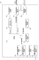
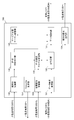
- FIG. 1 is a block diagram showing a connection configuration of a communication system 10 according to the first embodiment.
- the communication system 10 includes a terminal 110, a small base station 120, a third party server 130, a security gateway 140, and a mobile network management node group 150.
- the terminal 110 is a mobile terminal device owned by an end user, and performs wireless communication with the small base station 120.
- the small base station 120 is a small base station device that provides a communication connection service to a small coverage area represented by a femtocell. Such a small base station that covers a femtocell may be referred to as a femto base station, a femtocell base station, or a home base station.
- the small base station 120 is connected to the security gateway 140 using an encrypted connection via the Internet.
- the third party server 130 is a server installed in the same LAN as the small base station 120.
- the third party server 130 is connected to the small base station 120 via a LAN and provides various services to the terminal 110.
- the security gateway 140 is a gateway device installed at the boundary with the Internet in the operator network.
- the mobile network management node group 150 is in the operator network, and manages information used in the mobile network such as user information and terminal information, and controls and manages nodes in the operator network.
- the mobile network management node group 150 also serves as a gateway when the terminal 110 connects to a server or node on the Internet.
- FIG. 2 is a block diagram showing a specific configuration of the small base station 120.
- the small base station 120 includes a terminal communication unit 121, a terminal IP payout unit 122, a core network communication unit 123, a LAN communication unit 124, an I / F unit 125, a base station control unit 126, an ID generation / management.
- a response unit 127 and a table holding unit 128 are provided.
- the terminal communication unit 121 communicates with the terminal 110 under its own station.
- the terminal communication unit 121 receives a request for location / connection processing (location registration request) transmitted from the terminal 110 under its own station.
- the location / connection processing request received by the terminal communication unit 121 is sent to the core network communication unit 123 once after passing through the ID generation / management / response unit 127 to acquire the unique ID of the terminal 110. Further, the terminal communication unit 121 returns a response to the location / connection process received from the ID generation / management / response unit 127 to the terminal 110.
- the terminal IP address issuing unit 122 receives a connection request to the LAN side transmitted from the terminal 110 under its own station via the terminal communication unit 121, and issues an IP address to the terminal 110.
- the terminal IP address issuing unit 122 issues an IP address to communicate with each terminal under the small base station 120 via the LAN
- the ID generation / management / response unit 127 also receives the issued IP address. Notice.
- the ID generation / management / response unit 127 can store the set of the user unique ID and the assigned IP address in the table holding unit 128 in association with each other.
- the core network communication unit 123 performs communication with nodes in the operator network.
- the core network communication unit 123 transmits the location / connection processing request from the terminal 110 received from the ID generation / management / response unit 127 to the mobile network management node group 150 via the I / F unit 125. Further, the core network communication unit 123 receives a location / connection processing response, which is a response to the request transmitted from the mobile network management node group 150, via the I / F unit 125.
- the received presence / connection processing response is transmitted from the terminal communication unit 121 to the terminal 110 after passing through the ID generation / management / response unit 127 to acquire the unique ID of the terminal 110.
- the LAN communication unit 124 communicates with nodes in the LAN.
- the LAN communication unit 124 communicates with the nodes in the LAN based on the data request received by the terminal communication unit 121.
- the I / F unit 125 is a physical interface to the outside of the core network communication unit 123 and the LAN communication unit 124.
- the base station control unit 126 controls the small base station 120 itself based on information received and transmitted by the terminal communication unit 121, the core network communication unit 123, and the LAN communication unit 124, respectively.
- the ID generation / management / response unit 127 receives ID information unique to the user through the core network communication unit 123 or the terminal communication unit 121 for each access from the terminal, and stores the ID information in the table holding unit 128. Specifically, a user-specific ID (hereinafter referred to as a user-specific ID) from a request for a location / connection process sent through the terminal communication unit 121 or a response to a location / connection process sent through the core network communication unit 123 It is taken out and stored in the table holding unit 128.
- a user-specific ID hereinafter referred to as a user-specific ID
- the user-specific ID is usually recorded on the SIM card in the terminal for the purpose of providing different services for each user and charging different for each user.
- the user unique ID is transmitted to the operator network at the time of attachment from the terminal to the base station, for example.
- a femtocell can acquire an ID called IMSI (International Mobile Subscriber Identity) of a subordinate terminal.
- IMSI International Mobile Subscriber Identity
- the ID is not necessarily limited to 3GPP IMSI, and may be a user-specific ID in 3GPP2 or WiMAX.
- the ID generation / management / response unit 127 associates the IP address issued by the terminal IP address issuing unit 122 with respect to the terminal 110 and the user unique ID of the terminal 110 and stores them in the table holding unit 128. .
- the ID generation / management / response unit 127 generates and sends a unique ID to the terminal 110, which is valid only for the third party server 130, to the third party server 130 on the LAN side.
- a temporary identifier for identifying the terminal 110 generated by the ID generation / management / response unit 127 based on the IP address of the terminal is referred to as a user-specific temporary ID.
- the same user ID is assigned unless the user cancels the contract with the operator.
- the user-specific temporary ID of the present invention is an ID that is always and uniquely assigned to a third party when the terminal 110 is located under a small base station 120.
- the user-specific temporary ID is generated for the purpose of relaxing security requirements to some extent and assigning a different terminal ID for each third party, instead of using the ID used in the operator network. For example, if a user-specific temporary ID managed by a third party leaks, it can be dealt with by generating another ID only for that third party.
- the user-specific temporary ID of the present invention is TMSI (Temporary Mobile Subscriber Identity) that the terminal 110 generates based on the IMSI stored in the SIM in 3GPP, except that it is common in terms of a temporary ID, It is a different concept ID that differs in various respects, such as the purpose of use, the subject to be generated, and timing.
- TMSI Temporal Mobile Subscriber Identity
- the ID generation / management / response unit 127 may obtain the IP address of the third-party server 130 at the timing of receiving an inquiry using the terminal IP address as key information and store it in the table holding unit 128.
- the ID generation / management / response unit 127 is configured to generate a user-specific temporary ID and send it to the third-party server 130 when the third-party server 130 makes an inquiry using the IP address of the terminal 110 as key information. There may be.
- the ID generation / management / response unit 127 may store the third party ID and the third party IP address in the table holding unit 128 by receiving the third party ID and the third party IP address in advance by subscribe from the third party server 130.
- the location notification destination for the subscribe from the third party server 130 does not necessarily have to be the server that sent the subscribe, but may be another server of the same third party.
- the user unique temporary ID generated by the ID generation / management / response unit 127 includes the user unique ID, the user unique temporary ID generated for another third-party server, the IP address assigned to the terminal, It is stored in the table holding unit 128 together with the IP address that has been paid out.
- a method of generating a user unique temporary ID for example, a method of calculating a hash value after combining information such as IMSI held by the terminal 110 and an IP address of a third party server to which the ID is provided as a character string Can be considered.
- the means for generating the user-specific temporary ID is not necessarily limited to this, and may be any means that is uniform to the server and does not output 3G network information to the outside.
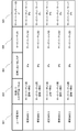
- the stored IP address and the generated user unique temporary ID are stored in the table holding unit 128, for example, in the format shown in FIG.
- the ID storage form is not necessarily limited to this.
- the ID storage form is unique within the third-party server 130 or a group of third-party servers. It only needs to be able to respond with a valid ID.
- the table holding unit 128 holds user unique IDs in the column 901. There are as many entries as the number of third parties for one terminal 110.
- a user unique temporary ID assigned for each third party is managed using the user unique ID as a key (902).
- the user-specific temporary ID is managed as an ID that does not change even if the IP address assigned to the terminal 110 changes, even after the terminal 110 becomes non-resident.
- the IP address is issued by the small base station 120 to the terminal 110 currently located in the small base station 120 at that time.
- the third party ID as the possession or management entity of the third party server 130 in the same LAN as the small base station 120 and the IP address of the third party server 130 are shown.
- the table size of the table stored in the table holding unit 128 of the small base station 120 may be reduced by transferring information from the small base station 120 to another server. .
- the table holding unit 128 does not necessarily have to be provided in all the small base stations 120, and the table managed by the table holding unit 128 of each small base station 120 may be centrally managed by placing it on another server. .
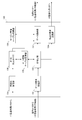
- the terminal a110 performs a location / connection process for the mobile network management node group 150 via the small base station 120 (step S501).
- the mobile network management node group 150 returns the located area / connection processing response to the terminal 110 via the small base station 120 (step S502).
- the small base station 120 acquires the user unique ID of the terminal 110 when relaying the location / connection processing response to the terminal a110 from the mobile network management node group 150 (step S503). Specifically, the user unique ID acquisition process is performed by the ID generation / management / response unit 127 in the small base station 120.
- the small base station 120 generates a user unique temporary ID of the terminal a110 related to the user unique ID acquired in step S503 (step S504). Specifically, the ID generation / management / response unit 127 in the small base station 120 generates the user unique temporary ID and stores it in the table holding unit 128 in a state of being associated with the already acquired user unique ID. .
- step S503 indicates information held in the table holding unit 128 of the small base station 120 at this stage.
- the user unique ID acquired in step S503 and the user unique temporary ID generated in step S504 are associated with each other and stored in the internal table holding unit 128.
- the terminal a110 issues a connection request to the LAN side network to the small base station 120 when desiring to connect to the LAN side network (step S505).
- the timing of the connection request to the LAN side may be any timing after the terminal a110 issues a connection request to the mobile network management node group 150.
- the small base station 120 issues an IP address that can be used in the LAN side network to the terminal a110 (step S506), and notifies the IP address that has been issued by responding to the terminal a110 (step S506). S507).
- the IP address issued from the terminal a110 by the IP address issuing unit 122 in step S506 is associated with the already held user unique ID, user temporary unique ID, and ID generation / management / response unit 127 (step S508). ).
- the ID generation / management / response unit 127 uses the user unique ID already held for the terminal a110 by using the IP address issued by the IP address issuing unit 122 based on the LAN side connection request from the terminal a110. Further stored in the table holding unit 128 in association with the user temporary unique ID.
- step S506 indicates information held in the table holding unit 128 of the small base station 120 at this stage.
- the IP address newly issued in step S506 is shown to be further associated with the user unique ID and user temporary unique ID already stored up to step 504.
- the terminal a110 makes a data request to the third party server 130 connected to the LAN side network via the small base station 120 (step S509).
- the data request transmitted from the terminal a110 is a request using the IP address issued in step S506 as the transmission source address.
- the data request received by the terminal communication unit 121 from the terminal a 110 is sent to the LAN communication unit 124, and is sent from the LAN communication unit 124 to the third party server 130.
- the third-party server 130 that has received the data request detects the terminal address from the packet source address and uses it as a temporary ID of the terminal (step S510).
- the information regarding the terminal a110 held by the third party server 130 is only the IP address of the terminal a110 as indicated by 1003.
- the third party server 130 requests a terminal ID from the small base station 120 (step S511).
- the terminal ID request includes the IP address of the terminal related to the data request detected in step S510 as key information.
- the small base station 120 Based on the received terminal ID request, the small base station 120 performs processing to convert the IP address included in the terminal ID request into a terminal ID (step S512). Specifically, the ID generation / management / response unit 127 of the small base station 120 extracts a user-specific temporary ID associated with the IP address included in the terminal ID request received from the LAN communication unit 124.
- the ID generation / management / response unit 127 can be used only by the third-party server 130 that does not change even if the terminal IP address changes, instead of the terminal IP address that may change for each connection.
- the user unique temporary ID is paid out to the third party server 130 as a terminal ID.
- the ID of the third party server 130 to which the user unique temporary ID is assigned is matched.
- the small base station 120 responds to the terminal ID request including the user unique temporary ID converted and paid out in step S512 (step S513). That is, the small base station 120 notifies the third party server 130 of the user unique temporary ID as the terminal ID of the terminal a110.
- the third-party server 130 associates the IP address of the terminal a110 received in step S509 with the user unique temporary ID of the terminal a110 received in step S513 (step S514). That is, the third-party server 130 stores the newly notified user unique temporary ID of the terminal a110 in the internal storage unit in association with the IP address of the terminal a110 received and stored in step S509. To do. At this stage, the third-party server 130 holds the IP address and the user-specific temporary ID linked to each other as indicated by 1004.
- the third party server 130 makes a response to the data request in step S509 to the terminal a110 via the small base station 120 using the user unique temporary ID that is the terminal ID (step S515).
- step S503 the ID generation / management / response unit 127 of the small base station 120 has been described as generating the user unique temporary ID for the terminal a110 related to the user unique ID.
- the response unit 127 may generate a plurality of user-specific temporary IDs.
- step S512 the ID generation / management / response unit 127 selects one of the generated user-specific temporary IDs when paying out the user-specific temporary ID of the terminal a110 to the third-party server 130. Then you can pay out. With this configuration, different user-specific temporary IDs of the same terminal can be simply assigned to different third-party servers 130.
- step S501 the small base station 120 may acquire the IMSI which is the user unique ID from the location / connection processing request transmitted from the terminal a110.
- step S502, step S503, and step S504 is switched.
- the small base station 120 directly connects to the third party server 130 by traffic offload as the Internet connection from the terminal a110 has been described.
- the present invention is not limited to this.
- the small base station 120 may process the connection using the main route via the mobile network management node group 150.
- the base station apparatus is a base station apparatus capable of setting a plurality of routes for communication from a subordinate terminal, and has been in service for an ID request from the outside. And a means for responding to an ID related to the terminal. That is, a means for notifying an external server of an ID related to the terminal based on the location of the terminal is provided.
- the base station device generates a user unique temporary ID from the user unique ID and notifies the third party server, which is an external device, to the user as with the user unique ID. Uniqueness can be secured.
- the user unique temporary ID generated by the base station device based on the user unique ID is a terminal unique ID in the third party or the third party server. Can be closed.
- a user unique ID represented by IMSI is an ID used for user billing by an operator, is highly confidential, and may be misused if the ID leaks to the outside. Therefore, it is not preferable to use the user unique ID outside the mobile network from the viewpoint of the leakage.
- a small base station in order to adopt a configuration in which a small base station generates another ID that can uniquely identify a terminal based on such a highly confidential user unique ID and is used for each third party. , Leakage damage range can be closed to a third party.
- the ID providing means for providing the ID to the third party server does not depend on the protocol specification. Therefore, a means for obtaining a unique terminal ID with a third-party server can be constructed in a manner independent of the type of application.
- the small base station 120 when the small base station 120 described above is viewed from another viewpoint, the small base station 120 can be represented by a functional block illustrated in FIG. In FIG. 5, the small base station 120 includes a first identification information acquisition unit 210, a second identification information generation unit 220, and a terminal identification information notification unit 230.
- the three functional blocks correspond to the ID generation / management / response unit 127 shown in FIG.
- the first identification information acquisition unit 210 acquires first identification information for identifying a subordinate terminal.
- the first identification information corresponds to the above-described user unique ID, and specifically can be IMSI or TMSI.
- the first identification information is identification information that uniquely identifies the terminal in the mobile network. That is, in a mobile network including a plurality of base stations, the first identification information is identification information for identifying terminals in common by each base station.
- the second identification information generation unit 220 generates second identification information associated with the first identification information acquired by the first identification information acquisition unit 210.
- the second identification information corresponds to the user unique temporary ID described above.
- the second identification information is identification information for uniquely identifying a terminal in a local area network different from the mobile network.
- the second identification information is identification information for uniquely identifying a terminal between the base station included in the local area network and a third-party server that is an external device that provides a service. Therefore, when a plurality of external devices are included in the local area network, a plurality of second identification information is generated for each interval between the base station and the plurality of external devices.
- the second identification information for identifying a predetermined terminal shared between the base station and one external apparatus is the second identification information that identifies the predetermined terminal shared by the base station with another external apparatus. Different from the second identification information to be identified. That is, the second identification information is information that uniquely identifies a predetermined terminal between the base station and the external device, but uniquely identifies the predetermined terminal between the base station and another external device. Another second identification information for identifying is used.
- each second identification information for identifying a predetermined terminal is identification information that is valid only between the base station and the external device.
- the second identification information is determined between the base station and the external device group. It is possible to use identification information for identifying the terminal. In this case, each external device included in the same external device group shares the second identification information as information for uniquely identifying the predetermined terminal.
- the second identification information for identifying a predetermined terminal set between the external device and one base station identifies the predetermined terminal set between the external device and another base station device. This is different from the second identification information.
- the second identification information is information for identifying the terminal between the external device and the base station
- the second identification information generating means for generating the second identification information in the base station The second identification information may be generated based on the first identification information for identifying and the external device identification information for identifying the external device.
- the base station can generate different second identification information for each terminal and for each external device.
- an IP address of the external device may be used as the external device identification information.
- the second identification information is terminal identification information generated individually by each base station and shared with each external device, it is not used in common with other base stations. However, it is possible to add a configuration in which the second identification information is shared between a certain range of base stations. However, unlike the first identification information that is commonly used in the entire base station included in the mobile network, it remains limited to only a limited location or between service providers.
- the second identification information is different from the IP address.
- the IP address is an address on the network that is temporarily assigned to a terminal connected to the local area network. Therefore, when the terminal is removed from the base station, the IP address assigned to the terminal is released, and the released IP address is assigned to another terminal. In addition, when the terminal enters the base station again and tries to connect to the network, another IP address is assigned.
- the second identification information is identification information that is kept in a shared state between the base station and the external device even when the terminal is removed from the base station. Therefore, even a terminal that frequently departs from the area in which it is located can continue to be uniquely identified between the base station and the external device.
- the terminal identification information notification unit 230 notifies the external device of the second identification information generated by the second identification information generation unit 220 as information for identifying the terminal.
- the external device is a device connected to the small base station 120, such as a third party server, and is a service providing server that provides a service in response to a request from a terminal.
- the small base station 120 enters between the terminal under the subordinate and the external device, generates the user unique ID and notifies the external device, so that the service can be performed without using the highly confidential user unique ID. Management becomes possible.
- the small base station 120 when the small base station 120 described above in more detail is viewed from another viewpoint, it can be expressed by a functional block shown in FIG.
- the small base station 120 includes, in addition to the first identification information acquisition unit 210, the second identification information generation unit 220, and the terminal identification information notification unit 230, a location / connection processing request reception unit 240, In-zone / connection process request transmission unit 241, in-zone / connection process response reception unit 242, in-zone / connection process response transmission unit 243, LAN connection request reception unit 250, IP address allocation unit 260, management Unit 270 and a notification request receiving unit 280.
- the location / connection processing request reception unit 240 and the location / connection processing response transmission unit 243 receive the location / connection processing request transmission unit 241 and the location / connection processing response reception from the terminal communication unit 121.
- the units 242 correspond to the core network communication unit 123, respectively.
- the LAN connection request receiving unit 250 and the notification request receiving unit 280 correspond to the LAN communication unit 124
- the IP address assignment unit 260 corresponds to the terminal IP address issuing unit 122.
- the first identification information acquisition unit 210, the second identification information generation unit 220, and the management unit 270 correspond to the ID generation / management / response unit 127, respectively.
- the location / connection processing request receiving unit 240 receives a location / connection processing request including first identification information transmitted from a terminal under its own station.
- the location / connection processing request is sent to the location / connection processing request transmission unit 241.
- the location / connection processing request transmission unit 241 transmits the location / connection processing request to the mobile network management node, which is an external host device (upper node).
- the location / connection process response reception unit 242 is a response to the location / connection process request, and receives a location / connection process response including first identification information transmitted from the mobile network management node, which is the host device. Receive. The location / connection process response is sent to the location / connection process response transmission unit 243.
- the location / connection process response transmission unit 243 transmits the location / connection process response to the terminal.
- the first identification information acquisition unit 210 can acquire the first identification information from the location / connection processing request received by the location / connection processing request reception unit 240.
- the first identification information acquisition unit 210 can also acquire the first identification information from the location / connection process response received by the location / connection process response reception unit 242. Since such a connection process includes a user unique ID such as IMSI, the ID can be used as the first identification information.
- the second identification information generation unit 220 generates second identification information based on the first identification information acquired by the first identification information acquisition unit 210.
- the second identification information generated by the second identification information generation unit 220 is once sent to the management unit 270 and then notified from the terminal identification information notification unit 230 to the external device.
- the LAN connection request receiving unit 250 receives a LAN connection request which is a request for connection to the LAN from a terminal under its own station.
- the LAN connection request reception unit 250 sends the received LAN connection request to the IP address assignment unit 260.
- the IP address assignment unit 260 assigns an IP address to the terminal.
- the IP address assignment unit 260 assigns an IP address to the requesting terminal of the LAN connection request based on the LAN connection request received by the LAN connection request reception unit 250.
- the management unit 270 manages the first identification information, the second identification information, and the IP address in association with each other.
- a plurality of identification information is managed by storing a management table in which the correspondence is collected in a storage unit (table holding unit) inside the small base station 120.
- the notification request receiving unit 280 receives an information notification request for uniquely identifying a terminal under the base station 120 from an external device such as a third party server.
- the notification request receiving unit 280 sends the received notification request to the terminal identification information notification unit 230.
- the notification request includes the IP address of the terminal.
- the terminal identification information notification unit 230 Upon receiving the notification request received by the notification request receiving unit 280, the terminal identification information notification unit 230 sends the IP address included in the notification request to the management unit 270 as search key information, and the management unit 270 The second identification information of the terminal stored in association is received.
- the terminal identification information notification unit 230 notifies the external device of the second identification information of the terminal received from the management unit 270 using the IP address of the terminal as a key.
- the small base station is located on the path between the cellular network and the LAN network, and the unique ID used in the cellular network for the server on the LAN side. Can be provided to the server on the LAN side.
- the IP address and the ID are always issued to a terminal under a certain small base station, the correspondence between the IP address and the ID can be maintained. As a result, even if the IP address assigned to the same terminal changes, the same ID can be responded to an inquiry from a third party server using the IP address as a key.
- the third party server 130 includes a data request receiving unit 131, a terminal ID specifying unit 132, an IP-ID conversion table storage unit 133, a terminal ID request transmitting unit 134, a terminal ID receiving unit 135, and an IP-ID association unit. 136, a service providing unit 137, and a service management table storage unit 138.
- the data request receiving unit 131 receives the data request transmitted from the terminal a110 via the small base station 120.
- the data request includes the IP address of the terminal a110.
- the data request receiving unit 131 sends the received data request to the terminal ID specifying unit 132.
- the terminal ID specifying unit 132 specifies the terminal ID of the terminal a110 related to the data request received from the data request receiving unit 131. Specifically, referring to the IP-ID conversion table stored in the IP-ID conversion table storage unit 133, the ID associated with the IP address included in the data request received from the data request receiving unit 131 is acquired. To do.
- the terminal ID specifying unit 132 sends the IP address included in the data request received from the data request receiving unit 131 and the specified ID to the service providing unit 137.
- the terminal ID specifying unit 132 stores the IP address as a new entry in the IP-ID conversion table, and also transmits a terminal ID request transmitting unit.
- a terminal ID request instruction is issued to 134.
- the IP-ID conversion table storage unit 133 stores an IP-ID conversion table in which correspondences between IP addresses and terminal IDs are collected.
- the terminal ID request unit 134 transmits a terminal ID request to the small base station 120 based on an instruction from the terminal ID specifying unit 132.
- the terminal ID request unit 134 transmits a terminal ID request including the IP address of the terminal sent from the terminal ID specifying unit 132 together with the terminal ID request instruction.
- the terminal ID receiving unit 135 receives a response to the terminal ID request transmitted by the terminal ID requesting unit 134.
- the response includes a terminal ID.
- the terminal ID is a user unique temporary ID (second identification information) generated by the small base station 120.
- the terminal ID receiving unit 135 sends the received terminal ID to the IP-ID association unit 136.
- the IP-ID association unit 136 associates the terminal ID received from the terminal ID reception unit 135 with the IP address of the terminal. Specifically, the terminal ID received from the terminal ID receiving unit 135 is associated with the IP address of the terminal stored in the IP-ID conversion table entry stored in the IP-ID conversion table storage unit 133. . Also, the IP-ID association unit 136 sends the terminal ID and IP address related to the terminal to the service providing unit 137.
- the service providing unit 137 provides a service based on the terminal ID received from the IP-ID association unit 136. That is, the service management table in which the association between the service and the terminal ID stored in the service management table storage unit 138 is referred to identify and provide the service associated with the terminal ID. Specifically, when the data request received by the data request receiving unit 131 is http request, the service providing unit 137 transmits http response based on the terminal ID to the terminal a110 via the small base station 120.
- the small base station according to the second embodiment is characterized in that the generation timing of the user unique temporary ID (second identification information) is different from that of the first embodiment.
- second identification information the generation timing of the user unique temporary ID
- the configuration of the small base station according to Embodiment 2 will be described with reference to FIG. 2 or FIG.
- a part of the description already given in the first embodiment is omitted.
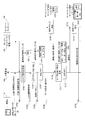
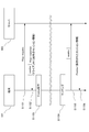
- FIG. 8 is a sequence diagram showing the operation of the communication system according to the second embodiment. Note that step S601 to step S603 and step S609 to step S615 in FIG. 8 are substantially the same as step S501 to step S503 and step S509 to step S515 in FIG.
- the small base station 320 When the small base station 320 according to the second embodiment receives the connection request to the LAN side network issued from the terminal a110 (step S604), it issues an IP address that can be used in the LAN side network (step S605). The issued IP address is notified to the terminal a110 (step S606).
- the small base station 320 After issuing the IP address to the terminal a110, the small base station 320 generates a user-specific temporary ID for the terminal a110 (step S607). Specifically, the ID generation / management / response unit 127 in the small base station 320 generates the user-specific temporary ID.
- the ID generation / management / response unit 127 associates the user unique temporary ID generated in step S607 with the user unique ID already acquired in step S603 and the IP address issued in step S605 in a table holding unit 128. To store.
- the table holding unit 128 is assigned to the terminal a110, the IMSI of the terminal a110, which is the user unique ID, the user unique temporary ID generated for the terminal a110, as indicated by 1102 in FIG.
- An IP address is associated and stored.
- the small base station generates a user-specific temporary ID for the terminal after waiting for a LAN-side connection request from the terminal.
- the user-specific temporary ID is actually required when access from the terminal side to the LAN side occurs. Therefore, it is possible to wait for this and generate a user-specific temporary ID in response to a request from a third-party server.
- a user-specific temporary ID can be assigned. Accordingly, in step S614 in FIG. 8, the IP address of the terminal and the user unique temporary ID assigned to the terminal can be stored in association with each other in the form indicated by 1104.
- the ID generation / management / response unit 127 may be configured to generate user-specific temporary IDs by the number of third-party servers 320 connected to the local station 320.
- the small base station according to the third embodiment is characterized in that the generation timing of the user unique temporary ID (second identification information) is different from the first and second embodiments.
- second identification information the generation timing of the user unique temporary ID
- the configuration of the small base station according to Embodiment 3 will be described with reference to FIG. 2 or FIG.
- a part of the description already given in the first and second embodiments is omitted.
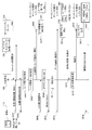
- FIG. 9 is a sequence diagram showing the operation of the communication system according to the third embodiment. Note that steps S701 to S706 and steps S708 to S710 in FIG. 9 are substantially the same as steps S601 to S606 and steps S609 to S611 in FIG.
- the small base station 420 stores the IP address assigned to the terminal a110 in step S705 in association with the user unique ID acquired in step S703 (step S707). At this stage, each identification information stored in the table holding unit 128 in the small base station 420 is in a state 1202.
- the small base station 420 When receiving the terminal ID request from the third party server 130 in step S710, the small base station 420 generates a user-specific temporary ID of the terminal a110 related to the terminal ID request (step S711). Subsequently, the user unique ID of the terminal a110, the user unique temporary ID of the terminal a110, and the IP address assigned to the terminal a110 are stored in association with each other as shown in 1204 (step S712).
- the small base station 420 transmits the user unique temporary ID of the terminal a110 generated for the third party server 130 to the third party server 130 based on the terminal ID request from the third party server 130 in step S710. (Step S713).
- the third-party server 130 stores the transmitted user-specific temporary ID and the IP address in association with each other as 1205 (step S714), and then responds according to the user-specific temporary ID (step S715). .
- the small base station based on the terminal ID request from the third party server 130, the small base station generates a user-specific temporary ID for the terminal. It is also possible to assign a user-specific temporary ID at such timing.
- the small base station according to the fourth embodiment is characterized in that the generation timing of the user unique temporary ID (second identification information) is different from that in the first to third embodiments.
- second identification information the generation timing of the user unique temporary ID
- FIG. 10 is a block diagram showing a configuration of small base station 520 according to the fourth embodiment.
- the small base station 520 includes a first identification information acquisition unit 210, a second identification information generation unit 220, a terminal identification information notification unit 230, a location / connection processing request reception unit 240, and a location / connection processing request transmission.
- Unit 241, location / connection process response reception unit 242, location / connection process response transmission unit 243, LAN connection request reception unit 250, IP address assignment unit 260, notification request reception unit 280, Subscribe request A receiving unit 521, a management unit 522, and a located area notification unit 523 are provided.
- the Subscribe request receiving unit 521 receives a Subscribe request transmitted from the third party server 530.
- the Subscribe request is an opportunity when the small base station 520 performs a so-called Subscribe process, which is a process of notifying the small base station of an ID related to the terminal or the terminal user when the terminal is located in the small base station.
- this is a request for a third party server that wants to receive a location notification in advance to have its small base station perform its own registration process.
- the Subscribe request includes server identification information for identifying the requesting third party server.
- the unique ID or IP address of the third-party server can be used as the server identification information.
- the Subscribe request receiving unit 521 instructs the management unit 522 to execute the Subscribe process when receiving the received Subscribe request.
- the management unit 522 executes a Subscribe process. Specifically, upon receiving a Subscribe processing execution instruction from the Subscribe request receiving unit 521, the management unit 522 stores the server identification information included in the Subscribe request in the internal storage unit as information for identifying the Subscribe target server. To do. When the first identification information acquisition unit 210 acquires the first identification information, the management unit 522 sends the second identification information generated by the second identification information generation unit 220 to the in-zone notification unit 523.
- the first identification information acquired by the first identification information acquisition unit 210, the second identification information generated by the second identification information generation unit 220, the IP address allocated by the IP address allocation unit 260, and the Subscribe request Management is performed in a state in which the server identification information received by the receiving unit 521 is associated.
- a management table in which the associations are collected in a storage unit (table holding unit) inside the small base station 520, the plurality of identification information is managed as shown in FIG.
- the in-zone notification unit 523 performs the in-zone notification including the second identification information transmitted based on the Subscribe process in the management unit 522 to the third party server 530.
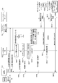
- the third-party server 530 transmits a subscribe request in order to execute a subscribe process for making the small base station 520 perform location notification in advance (step S801).
- the subscribe process is a process performed in advance for the third party server 530 to receive a presence notification from the small base station 520.
- the third party server 530 is ready to receive the location notification from the small base station 520.
- the terminal a110 performs a location / connection process for the mobile network management node group 150 via the small base station 520 (step S802).
- the mobile network management node group 150 returns the location / connection processing response to the terminal a110 via the small base station 520 (step S803).
- the small base station 520 acquires the user unique ID of the terminal 110 when relaying the location / connection processing response to the terminal a110 from the mobile network management node group 150 (step S804).
- the small base station 520 generates a user unique temporary ID for the terminal a110 related to the user unique ID acquired in step S804 (step S805).
- the small base station 520 generates the number of user-specific temporary IDs corresponding to the number of already recognized third party servers 530 by the subscribe process in step S801. That is, each user-specific temporary ID generated by the small base station 520 is a unique terminal ID for each third-party server 530.
- the small base station 520 transmits each user-specific temporary ID generated in step S805 to the third party server 530 that has been subscribed, together with the presence notification (step S806). That is, the small base station 520 notifies the third party server 530 that the terminal a110 has been located with a user-specific temporary ID that is a terminal ID unique to the third-party server. As a result, the third party server 530 can acquire the ID of the terminal a110 regardless of whether the terminal a110 performs LAN-side communication.
- Each third-party server 530 stores the user unique temporary ID of the terminal a110 transmitted from the small base station 520 in step S806 (step S807).
- the subscribe process generated in step S801 is not limited to that before step S802, but occurs as a third party server 530 is newly installed in the LAN.
- the small base station 520 additionally generates a user-specific temporary ID of the terminal a110 under its own station for the third-party server 530, along with the location notification. It may be transmitted to the third party server 530.
- the terminal a110 issues a connection request to the LAN side network to the small base station 520 (step S808).
- the connection request to the LAN side may be at an arbitrary timing after the terminal a 110 issues a connection request to the mobile network management node group 150.
- the small base station 520 issues an IP address that can be used in the LAN-side network to the terminal a110 (step S809), and notifies the terminal a110 of the issued IP address (step S810).
- the IP address issued by the small base station 520 from the terminal 110a is associated with the user unique ID and the user temporary unique ID (step S811).
- the ID for identifying the third party server 530 acquired in step S801 the user unique ID of the terminal a110 acquired in step S804, and the third party server 530 of the terminal a110 generated in step S805.
- the user unique temporary ID is associated with the IP address of the terminal a110 assigned in step S809.
- the third party server 530 side at this stage receives and stores the user-specific temporary ID of the terminal a110, but is not associated with other information.
- the terminal a110 makes a data request to the third party server 530 connected to the LAN side network via the small base station 520 (step S812).
- the third party server 530 detects the address of the terminal from the source address of the packet and uses it as a temporary ID of the terminal (step S813).
- the third-party server 530 at this stage there is no association between the user unique temporary ID already acquired in step S806 and the IP address of the terminal a110 detected and acquired in step S812.
- the third party server 530 requests a terminal ID from the small base station 520 (step S814).
- the terminal ID request transmitted from the third party server 530 to the small base station 520 includes the IP address of the terminal related to the request.
- the small base station 520 Based on the terminal ID request sent from the third party server 530, the small base station 520 converts the IP address of the terminal included in the terminal ID request into a user unique temporary ID (step S815). Specifically, the small base station 520 extracts the user unique temporary ID associated with the terminal IP address included in the terminal ID request and the ID for identifying the third party server 530.
- the small base station 520 transmits the user-specific temporary ID obtained in step S815 to the third party server 530 (step S816). Instead of the terminal IP address that may change for each connection, the small base station 520 uses a user-specific temporary ID that can be used only by the third-party server 530 that does not change even if the terminal IP address changes. Send to 530.
- the third-party server 530 that has received the user-specific temporary ID again performs association between the user-specific temporary ID of the terminal obtained in advance by the presence notification and the IP address of the terminal related to the received data request (Ste S817).
- the IP address of the terminal a110 and the user unique temporary ID are stored in the storage unit in a state of being associated with each other.
- the third party server 530 responds using the user-specific temporary ID (step S818).
- the base station is inquired so that the ID previously associated with the user when providing the service is associated with the IP destination address of the packet that came to the server via communication. Can do.
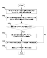
- FIG. 12 is a flowchart showing a specific operation flow of the IP-ID conversion processing in the small base station 520.
- FIG. 12 shows the operation of the small base station 520 after establishing the connection on the LAN side.
- the small base station 520 receives a terminal ID request, which is an ID inquiry using the IP address of the terminal as a key, from the third party server 530 (step S901).
- This step S901 corresponds to step S814 in FIG.
- the small base station 520 that has received the terminal ID request in step S901 searches the received IP address being inquired from the table of IP address and user-specific temporary ID pairs held in the table holding unit (step S901). S902). The small base station 520 determines whether or not a plurality of IP addresses are obtained as a search result by the search (step S903).
- step S903 If the small base station 520 obtains a plurality of identical IP addresses as a result of the determination in step S903 (step S903: YES), the small base station 520 confirms the source address of the terminal ID request received in step S901, and determines which third-party server It is specified whether the request is from (step S904).
- the small base station 520 selects an appropriate user unique temporary ID from the table (step S905). That is, the small base station 520 further selects an ID associated with the source address of the third-party server among the user-specific temporary IDs associated with the plurality of identical IP addresses obtained in step S903. Select as the user-specific temporary ID of the terminal related to the inquiry for the third-party server.
- step S903 if the small base station 520 obtains one IP address as a result of the determination in step S903 (step S903: No), the small base station 520 jumps to step S905 and is associated with the IP address obtained in step S903.
- the unique temporary ID is extracted from the above table.
- the small base station 520 transmits the ID selected in step S905 to the third party server 530 as the ID inquiry source as the terminal ID of the terminal related to the inquiry (step S906).
- step S904 Even if only one IP address is obtained as a search result, such as when there is only one third-party server, the third-party ID and third-party server IP address confirmation processing in step S904 is performed. You may perform the process of step S905.
- the key to be paid out does not necessarily have to be the source address of the ID inquiry, and it is sufficient if the inquiry shows the ID of the third party server that is the inquiry source.
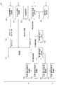
- FIG. 13 is a block diagram showing a configuration of the third-party server 530 according to the fourth embodiment.
- the third party server 530 further includes a Subscribe request unit 531 and a location notification receiving unit 532 as compared to the third party server 130 described with reference to FIG. The invention is omitted for the parts already described in FIG.
- the Subscribe request unit 531 transmits a Subscribe request to the small base station 520 that wants to execute the Subscribe process. At this time, the Subscribe request unit 531 transmits the Subscribe request including the IP address of the own server and an ID for identifying the own server in the Subscribe request.
- the location notification receiving unit 532 receives a location notification indicating that the terminal is under the small base station 520 notified from the small base station 520 based on the Subscribe request.
- the location notification includes a user-specific temporary ID that identifies the terminal.
- the location notification receiving unit 532 stores the user-specific temporary ID included in the received location notification in the IP-ID conversion table storage unit 133.
- the user-specific temporary ID is stored from the in-zone notification receiving unit 532, and the IP address is stored from the terminal ID specifying unit 132.
- the IP-ID association unit 136 selects an appropriate user-specific temporary ID and IP address stored in the IP-ID conversion table storage unit 133. Select two and link them.
- the IP-ID association unit 136 performs the association, the user-specific temporary ID and the IP address of the same terminal are associated with each other and stored in the IP-ID conversion table.
- the user-specific temporary ID notified by the presence trigger when combined with the presence trigger, can be associated with the IP address, and there is no access from the terminal However, the user can be specified. Further, when the communication from the terminal thereafter matches, the user unique temporary ID obtained by the location trigger and the ID by the subsequent communication can be linked in the third party server.
- user-specific temporary IDs that serve as a key for providing services to users who do not generate communication and user-specific temporary IDs that serve as keys for providing services through subsequent communication can be handled in a lump. Can be handled uniformly.
- the reason is to use the terminal IP address and the terminal by comparing the user unique temporary ID obtained from the base station with the IP address as a key and the user unique temporary ID in the location trigger received from the base station in advance. This is because the user-specific temporary ID can be linked in the third-party server.
- the above IDs do not necessarily need to be assigned to each server and each terminal, and the same terminal ID may be used in the LAN as long as it is different for each terminal.
- the above ID does not necessarily have to be different for each third party, may be different for each third party server, or the same ID may be used in the same LAN without distinguishing the third party. .
- the third-party server exists in the LAN of the same segment as the femtocell (small base station), and the femtocell LIPA (Local IP IP Access) that communicates using a private IP address is used.
- the femtocell LIPA Local IP IP Access
- the present invention is not limited to this.
- a third party server may exist outside the LAN.
- NAPT Network Address Port Translation
- the third-party server subscribes to the femtocell remotely from outside the LAN, and the femtocell provides a user-specific temporary ID (second identification information) to the third-party server located outside the LAN. It is also possible to take such a network configuration.
- the small base station of the present invention is not necessarily limited to a small base station as compared with the conventional one such as a femtocell, and may be any one that provides two network paths to a terminal.
- each block described in each of the above embodiments can be configured to be realized by causing an information processing device (CPU: Central Processing Unit) to execute a program.
- CPU Central Processing Unit
- Non-transitory computer readable media include various types of tangible storage media (tangible storage medium). Examples of non-transitory computer-readable media include magnetic recording media (eg flexible disks, magnetic tapes, hard disk drives), magneto-optical recording media (eg magneto-optical discs), CD-ROMs (Read Only Memory), CD-Rs, CD-R / W, semiconductor memory (for example, mask ROM, PROM (Programmable ROM), EPROM (Erasable ROM), flash ROM, RAM (random access memory)) are included.
- the program may also be supplied to the computer by various types of temporary computer-readable media. Examples of transitory computer readable media include electrical signals, optical signals, and electromagnetic waves.
- the temporary computer-readable medium can supply the program to the computer via a wired communication path such as an electric wire and an optical fiber, or a wireless communication path.
- the present invention can take the form of a terminal ID providing system, a terminal ID providing method, and a terminal ID providing program, and a small base station has an ID holding table, and the terminal is determined from the IP address assigned to the terminal. It can take the form of a communication system including a small base station that responds to an ID related to the communication method, a communication method, and a communication program.
- (Appendix 1) First identification information acquisition means for acquiring first identification information for identifying a terminal under its control; Second identification information generating means for generating second identification information associated with the first identification information acquired by the first identification information acquiring means; Terminal identification information notifying means for notifying an external device of the second identification information generated by the second identification information generating means as information for identifying the terminal;
- a base station apparatus comprising: (Appendix 2) A notification request receiving means for receiving a notification request for information identifying the terminal from the external device; The terminal identification information notifying unit notifies the external device of the second identification information as information for identifying the terminal based on the notification request received by the notification request receiving unit. Base station equipment.
- the base station apparatus according to (Appendix 2), further comprising management means for managing the first identification information, the second identification information, and the IP address of the terminal in association with each other.
- the notification request for information identifying the terminal includes the IP address of the terminal,
- the terminal identification information notifying unit notifies the second identification information associated with the IP address included in the notification request received by the notification request receiving unit in the management unit, (Appendix 3) Base station device.
- (Appendix 5) Visiting / connection processing request receiving means for receiving a visiting / connection processing request including the first identification information transmitted from the terminal; A location / connection processing request transmission means for transmitting the location / connection processing request received by the location / connection processing request reception means to an external host device; Comprising The base according to (Appendix 1 to 4), wherein the first identification information acquisition unit acquires the first identification information from the location / connection processing request received by the location / connection processing request reception unit. Station equipment.
- a location / connection processing request receiving means for receiving a location / connection processing request transmitted from the terminal;
- a location / connection processing request transmission means for transmitting the location / connection processing request received by the location / connection processing request reception means to an external host device;
- a response to the location / connection processing request, a location / connection processing response receiving means for receiving a location / connection processing response including the first identification information transmitted from the host device;
- the second identification information generating means generates a plurality of different second identification information associated with the first identification information acquired by the first identification information acquisition means,
- the terminal identification information notifying means as information for identifying the terminal for each of the plurality of different external devices, based on a notification request for information identifying the terminal transmitted from each of the plurality of different external devices.
- the base station apparatus according to any one of (Appendix 1 to 6), which selects and notifies any one of the plurality of different second identification information generated by the second identification information generation unit.
- (Appendix 8) Further comprising a subscribe request receiving means for receiving a subscribe request from the external device;
- the second identification information generating means generates the second identification information associated with the external device and the first identification information,
- the terminal identification information notifying means notifies the external device of the second identification information generated by the second identification information generating means together with a response to the subscribe request as information for identifying the terminal (Appendix 1). )
- Base station apparatus as described.
- the subscribe request includes external device identification information for identifying the external device;
- the base station apparatus according to (Appendix 8), wherein the second identification information generation unit generates the second identification information associated with the external apparatus identification information and the first identification information.
- the base station apparatus according to (Appendix 10) The base station apparatus according to (Appendix 9), further comprising management means for managing a correspondence relationship among the first identification information, the second identification information of the terminal, the IP address of the terminal, and the external apparatus identification information.
- the second identification information generation means uses the hash value obtained based on the first identification information acquired by the first identification information acquisition means and the external apparatus identification information for identifying the external apparatus as the second identification information.
- Bases 1 to 11 (Appendix 13)
- the base station apparatus according to (Appendix 1 to 12) is a femtocell.
- a communication system including a base station device that can be wirelessly connected to a subordinate terminal and a service providing server connected to the base station device,
- the base station device First identification information acquisition means for acquiring first identification information for identifying the subordinate terminal;
- Second identification information generating means for generating second identification information associated with the first identification information acquired by the first identification information acquiring means;
- Terminal identification information notifying means for notifying the service providing server of the second identification information generated by the second identification information generating means as information for identifying the terminal;
- the service providing server includes: Second identification information receiving means for receiving second identification information notified from the base station; Service providing means for providing a service based on the second identification information received by the second identification information receiving means; Comprising Communications system.
Landscapes
- Engineering & Computer Science (AREA)
- Computer Networks & Wireless Communication (AREA)
- Signal Processing (AREA)
- Computer Security & Cryptography (AREA)
- Databases & Information Systems (AREA)
- Mobile Radio Communication Systems (AREA)
- Data Exchanges In Wide-Area Networks (AREA)
Description
以下、図面を参照して本発明の実施の形態について説明する。図1は、本実施の形態1に係る通信システム10の接続構成を示すブロック図である。通信システム10は、端末110と、小型基地局120と、サードパーティサーバ130と、セキュリティゲートウェイ140と、モバイルネットワーク管理ノード群150と、を含んで構成される。
本実施の形態2に係る小型基地局は、ユーザ固有一時ID(第2識別情報)の生成タイミングが実施の形態1と異なることを特徴とする。以下、図面を用いて説明する。なお、本実施の形態2に係る小型基地局の構成については、図2又は図6を流用して説明する。その他、実施の形態1で既に説明した部分については一部説明を省略する。
本実施の形態3に係る小型基地局は、ユーザ固有一時ID(第2識別情報)の生成タイミングが実施の形態1、2と異なることを特徴とする。以下、図面を用いて説明する。なお、本実施の形態3に係る小型基地局の構成については、図2又は図6を流用して説明する。その他、実施の形態1、2で既に説明した部分については一部説明を省略する。
本実施の形態4に係る小型基地局は、ユーザ固有一時ID(第2識別情報)の生成タイミングが実施の形態1~3と異なることを特徴とする。以下、図面を用いて説明する。但し、実施の形態1~3において既に説明した部分については、発明の明確化のため一部説明を省略する。
配下の端末を識別する第1識別情報を取得する第1識別情報取得手段と、
前記第1識別情報取得手段で取得された第1識別情報に対応付けた第2識別情報を生成する第2識別情報生成手段と、
前記第2識別情報生成手段で生成された前記第2識別情報を、前記端末を識別する情報として外部装置に通知する端末識別情報通知手段と、
を具備する基地局装置。
(付記2)
前記外部装置より前記端末を識別する情報の通知要求を受信する通知要求受信手段を更に具備し、
前記端末識別情報通知手段は、前記通知要求受信手段で受信された前記通知要求に基づいて、前記端末を識別する情報として前記第2識別情報を前記外部装置に通知する、(付記1)に記載の基地局装置。
(付記3)
前記端末にIPアドレスを割り当てるIPアドレス割り当て手段と、
前記端末の前記第1識別情報と前記第2識別情報と前記IPアドレスとを対応付けて管理する管理手段とを更に具備する、(付記2)に記載の基地局装置。
(付記4)
前記端末を識別する情報の通知要求は、前記端末のIPアドレスが含まれ、
前記端末識別情報通知手段は、前記管理手段において前記通知要求受信手段で受信された通知要求に含まれるIPアドレスと対応付けられている前記第2識別情報を通知する、(付記3)に記載の基地局装置。
(付記5)
前記端末から送信される前記第1識別情報を含む在圏・接続処理要求を受信する在圏・接続処理要求受信手段と、
前記在圏・接続処理要求受信手段で受信された在圏・接続処理要求を外部の上位装置へ送信する在圏・接続処理要求送信手段と、
を具備し、
前記第1識別情報取得手段は、前記在圏・接続処理要求受信手段で受信された在圏・接続処理要求の中から前記第1識別情報を取得する、(付記1~4)に記載の基地局装置。
(付記6)
前記端末から送信される在圏・接続処理要求を受信する在圏・接続処理要求受信手段と、
前記在圏・接続処理要求受信手段で受信された在圏・接続処理要求を外部の上位装置へ送信する在圏・接続処理要求送信手段と、
前記在圏・接続処理要求に対する応答であって、前記上位装置より送信される前記第1識別情報を含む在圏・接続処理応答を受信する在圏・接続処理応答受信手段と、
を具備し、
前記第1識別情報取得手段は、前記在圏・接続処理応答受信手段で受信された在圏・接続処理応答の中から前記第1識別情報を取得する、(付記1~4)に記載の基地局装置。
(付記7)
第2識別情報生成手段は、前記第1識別情報取得手段で取得された第1識別情報に対応付けた複数の異なる第2識別情報を生成し、
前記端末識別情報通知手段は、複数の異なる外部装置よりそれぞれ送信された前記端末を識別する情報の通知要求に基づいて、前記複数の異なる外部装置の各々に対して、前記端末を識別する情報として前記第2識別情報生成手段で生成された前記複数の異なる第2識別情報のいずれかを選択して通知する、(付記1~6)のいずれか1項に記載の基地局装置。
(付記8)
前記外部装置よりサブスクライブ要求を受信するサブスクライブ要求受信手段を更に具備し、
前記第2識別情報生成手段は、前記外部装置と前記第1識別情報とに対応付けた前記第2識別情報を生成し、
前記端末識別情報通知手段は、前記サブスクライブ要求に対する応答と共に前記第2識別情報生成手段で生成された前記第2識別情報を、前記端末を識別する情報として前記外部装置に通知する、(付記1)記載の基地局装置。
(付記9)
前記サブスクライブ要求は、前記外部装置を識別する外部装置識別情報を含み、
前記第2識別情報生成手段は、前記外部装置識別情報と前記第1識別情報とに対応付けた前記第2識別情報を生成する、(付記8)記載の基地局装置。
(付記10)
前記端末の前記第1識別情報と前記第2識別情報と前記端末のIPアドレスと前記外部装置識別情報との対応関係を管理する管理手段を更に具備する、(付記9)記載の基地局装置。
(付記11)
前記第1識別情報は、前記端末のIMSI(International Mobile Subscriber Identity)である、(付記1~9)に記載の基地局装置。
(付記12)
前記第2識別情報生成手段は、第1識別情報取得手段で取得された第1識別情報と前記外部装置を識別する外部装置識別情報に基づいて求めたハッシュ値を前記第2識別情報とする、(付記1~11)記載の基地局装置。
(付記13)
(付記1~12)に係る基地局装置はフェムトセルである、基地局装置。
(付記14)
配下の端末と無線接続可能な基地局装置と基地局装置と接続されたサービス提供サーバとを含む通信システムであって、
前記基地局装置は、
前記配下の端末を識別する第1識別情報を取得する第1識別情報取得手段と、
前記第1識別情報取得手段で取得された第1識別情報に対応付けた第2識別情報を生成する第2識別情報生成手段と、
前記第2識別情報生成手段で生成された前記第2識別情報を、前記端末を識別する情報として前記サービス提供サーバに通知する端末識別情報通知手段と、
を具備し、
前記サービス提供サーバは、
前記基地局より通知された第2識別情報を受信する第2識別情報受信手段と、
前記第2識別情報受信手段で受信された第2識別情報に基づくサービスを提供するサービス提供手段と、
を具備する、
通信システム。
102 小型基地局
103 サードパーティサーバ
105 モバイルネットワーク管理ノード群 110 端末
120 小型基地局 121 端末通信部
122 端末IPアドレス払い出し部 123 コア網通信部
124 LAN通信部 125 I/F部
126 基地局制御部
127 生成・管理・応答部
128 テーブル保持部
130 サードパーティサーバ
131 データ要求受信部 132 端末ID特定部
133 変換テーブル記憶部 134 端末ID要求送信部
135 端末ID受信部 136 IP-ID対応付け部
137 サービス提供部
138 サービス管理テーブル記憶部
140 セキュリティゲートウェイ
150 モバイルネットワーク管理ノード群
210 第1識別情報取得部
220 第2識別情報生成部
230 端末識別情報通知部
240 在圏・接続処理要求受信部
241 在圏・接続処理要求送信部
242 在圏・接続処理応答受信部
243 在圏・接続処理応答送信部 250 LAN接続要求受信部
260 IPアドレス割り当て部 270 管理部
280 通知要求受信部 320 小型基地局
420 小型基地局 520 小型基地局
521 Subscribe要求受信部 522 管理部
523 在圏通知部
530 サードパーティサーバ
531 Subscribe要求部 532 在圏通知受信部
Claims (10)
- 配下の端末を識別する第1識別情報を取得する第1識別情報取得手段と、
前記第1識別情報取得手段で取得された前記第1識別情報に対応付けた第2識別情報を生成する第2識別情報生成手段と、
前記第2識別情報生成手段で生成された前記第2識別情報を、前記端末を識別する情報として外部装置に通知する端末識別情報通知手段と、
を具備する基地局装置。 - 前記外部装置より前記端末を識別する情報の通知要求を受信する通知要求受信手段を更に具備し、
前記端末識別情報通知手段は、前記通知要求受信手段で受信された前記通知要求に基づいて、前記端末を識別する情報として前記第2識別情報を前記外部装置に通知する、
請求項1に記載の基地局装置。 - 前記端末にIPアドレスを割り当てるIPアドレス割り当て手段と、
前記端末の前記第1識別情報と前記第2識別情報と前記IPアドレスとを対応付けて管理する管理手段とを更に具備する、
請求項2に記載の基地局装置。 - 前記端末を識別する情報の通知要求は、前記端末のIPアドレスが含まれ、
前記端末識別情報通知手段は、前記管理手段において前記通知要求受信手段で受信された通知要求に含まれるIPアドレスと対応付けられている前記第2識別情報を通知する、
請求項3に記載の基地局装置。 - 前記端末から送信される前記第1識別情報を含む在圏・接続処理要求を受信する在圏・接続処理要求受信手段と、
前記在圏・接続処理要求受信手段で受信された在圏・接続処理要求を外部の上位装置へ送信する在圏・接続処理要求送信手段と、
を具備し、
前記第1識別情報取得手段は、前記在圏・接続処理要求受信手段で受信された在圏・接続処理要求の中から前記第1識別情報を取得する、
請求項1乃至4に記載の基地局装置。 - 前記端末から送信される在圏・接続処理要求を受信する在圏・接続処理要求受信手段と、
前記在圏・接続処理要求受信手段で受信された在圏・接続処理要求を外部の上位装置へ送信する在圏・接続処理要求送信手段と、
前記在圏・接続処理要求に対する応答であって、前記上位装置より送信される前記第1識別情報を含む在圏・接続処理応答を受信する在圏・接続処理応答受信手段と、
を具備し、
前記第1識別情報取得手段は、前記在圏・接続処理応答受信手段で受信された在圏・接続処理応答の中から前記第1識別情報を取得する、
請求項1乃至4に記載の基地局装置。 - 第2識別情報生成手段は、前記第1識別情報取得手段で取得された第1識別情報に対応付けた複数の異なる第2識別情報を生成し、
前記端末識別情報通知手段は、複数の異なる外部装置よりそれぞれ送信された前記端末を識別する情報の通知要求に基づいて、前記複数の異なる外部装置の各々に対して、前記端末を識別する情報として前記第2識別情報生成手段で生成された前記複数の異なる第2識別情報のいずれかを選択して通知する、
請求項1乃至6のいずれか1項に記載の基地局装置。 - 前記外部装置よりサブスクライブ要求を受信するサブスクライブ要求受信手段を更に具備し、
前記第2識別情報生成手段は、前記外部装置と前記第1識別情報とに対応付けた前記第2識別情報を生成し、
前記端末識別情報通知手段は、前記サブスクライブ要求に対する応答と共に前記第2識別情報生成手段で生成された前記第2識別情報を、前記端末を識別する情報として前記外部装置に通知する、
請求項1記載の基地局装置。 - 前記サブスクライブ要求は、前記外部装置を識別する外部装置識別情報を含み、
前記第2識別情報生成手段は、前記外部装置識別情報と前記第1識別情報とに対応付けた前記第2識別情報を生成する、
請求項8記載の基地局装置。 - 配下の端末と無線接続可能な基地局装置と基地局装置と接続されたサービス提供サーバとを含む通信システムであって、
前記基地局装置は、
前記配下の端末を識別する第1識別情報を取得する第1識別情報取得手段と、
前記第1識別情報取得手段で取得された前記第1識別情報に対応付けた第2識別情報を生成する第2識別情報生成手段と、
前記第2識別情報生成手段で生成された前記第2識別情報を、前記端末を識別する情報として前記サービス提供サーバに通知する端末識別情報通知手段と、
を具備し、
前記サービス提供サーバは、
前記基地局より通知された第2識別情報を受信する第2識別情報受信手段と、
前記第2識別情報受信手段で受信された第2識別情報に基づくサービスを提供するサービス提供手段と、
を具備する、
通信システム。
Priority Applications (3)
| Application Number | Priority Date | Filing Date | Title |
|---|---|---|---|
| EP13743118.5A EP2811768B1 (en) | 2012-02-03 | 2013-01-16 | Base station device, communication system |
| JP2013556230A JP6191463B2 (ja) | 2012-02-03 | 2013-01-16 | 基地局装置、通信システム |
| US14/372,656 US9603007B2 (en) | 2012-02-03 | 2013-01-16 | Base station apparatus and communication system |
Applications Claiming Priority (2)
| Application Number | Priority Date | Filing Date | Title |
|---|---|---|---|
| JP2012022335 | 2012-02-03 | ||
| JP2012-022335 | 2012-02-03 |
Publications (1)
| Publication Number | Publication Date |
|---|---|
| WO2013114791A1 true WO2013114791A1 (ja) | 2013-08-08 |
Family
ID=48904844
Family Applications (1)
| Application Number | Title | Priority Date | Filing Date |
|---|---|---|---|
| PCT/JP2013/000140 Ceased WO2013114791A1 (ja) | 2012-02-03 | 2013-01-16 | 基地局装置、通信システム |
Country Status (4)
| Country | Link |
|---|---|
| US (1) | US9603007B2 (ja) |
| EP (1) | EP2811768B1 (ja) |
| JP (1) | JP6191463B2 (ja) |
| WO (1) | WO2013114791A1 (ja) |
Cited By (5)
| Publication number | Priority date | Publication date | Assignee | Title |
|---|---|---|---|---|
| JP2015211337A (ja) * | 2014-04-25 | 2015-11-24 | ソフトバンク株式会社 | 情報生成装置及び受信装置を備えたシステム |
| CN106454848A (zh) * | 2016-12-21 | 2017-02-22 | 荆楚理工学院 | 一种伪基站识别方法及设备 |
| JP2018528662A (ja) * | 2015-07-31 | 2018-09-27 | コンヴィーダ ワイヤレス, エルエルシー | スモールセルネットワークにおけるサービス層およびアプリケーションのための通知およびトリガ |
| JP2020060806A (ja) * | 2018-10-04 | 2020-04-16 | 富士電機株式会社 | 管理サーバ、自動販売機及び装置識別情報付与方法 |
| JPWO2022113370A1 (ja) * | 2020-11-30 | 2022-06-02 |
Families Citing this family (5)
| Publication number | Priority date | Publication date | Assignee | Title |
|---|---|---|---|---|
| US9961527B2 (en) | 2016-06-30 | 2018-05-01 | Verizon Patent And Licensing Inc. | Access control and scheduling mechanism for MTC devices |
| US20190014095A1 (en) * | 2017-07-06 | 2019-01-10 | At&T Intellectual Property I, L.P. | Facilitating provisioning of an out-of-band pseudonym over a secure communication channel |
| CN112073547B (zh) * | 2020-08-07 | 2022-05-24 | 新华三信息安全技术有限公司 | Ip地址申请方法和装置 |
| KR20220138632A (ko) | 2021-04-06 | 2022-10-13 | 삼성전자주식회사 | 무선 통신 시스템에서 임시 단말 식별자를 설정하는 방법 및 장치 |
| US12358624B2 (en) * | 2022-09-02 | 2025-07-15 | Panasonic Avionics Corporation | Secure access and presentation of passenger-specific information |
Citations (6)
| Publication number | Priority date | Publication date | Assignee | Title |
|---|---|---|---|---|
| JP2003189358A (ja) | 2001-12-14 | 2003-07-04 | Denso Corp | 端末局及び基地局データ中継装置 |
| JP2010041585A (ja) * | 2008-08-07 | 2010-02-18 | Fujitsu Ltd | 基地局およびデータ転送方法 |
| JP2010531094A (ja) * | 2007-06-15 | 2010-09-16 | エムフォーメイション テクノロジーズ インコーポレイテッド | 無線ネットワークにおけるデバイス識別情報とネットワークアドレスとの間のマッピングの自動的な検出及び報告のためのシステム及び方法 |
| WO2011045882A1 (ja) * | 2009-10-13 | 2011-04-21 | 日本電気株式会社 | 移動通信システム、ゲートウェイ装置、基地局装置、ゲートウェイ装置の制御方法、及びコンピュータ可読媒体 |
| JP2011135417A (ja) | 2009-12-25 | 2011-07-07 | Nec Corp | 基地局装置、基地局の制御方法、及びプログラム |
| WO2011092772A1 (ja) * | 2010-01-29 | 2011-08-04 | 日本電気株式会社 | サービス配信プラットフォーム、サービス配信システム、並びにサービス配信方法及びプログラム |
Family Cites Families (7)
| Publication number | Priority date | Publication date | Assignee | Title |
|---|---|---|---|---|
| JP3776705B2 (ja) * | 2000-09-28 | 2006-05-17 | 株式会社東芝 | 通信システム、移動端末装置、ゲートウェイ装置及び通信制御方法 |
| MXPA04005406A (es) | 2001-12-06 | 2004-10-11 | Access Co Ltd | Sistema y metodo para proporcionar servicios de contenido de subscripcion a dispositivos moviles. |
| JP3798769B2 (ja) | 2003-07-25 | 2006-07-19 | 日本テレコム株式会社 | データ通信装置及びデータ通信システム |
| JP2005051671A (ja) | 2003-07-31 | 2005-02-24 | Fujitsu Ltd | 加入者の個人情報を秘匿したサービス提供方法及びサービス提供システム並びに同システムに用いられる通信事業者装置及びサーバ装置 |
| JP4488369B2 (ja) | 2004-03-03 | 2010-06-23 | 三菱電機株式会社 | レイヤ2スイッチネットワークシステム |
| US7089033B2 (en) * | 2004-05-17 | 2006-08-08 | Nokia Corporation | Mobile terminal having UWB and cellular capability |
| JP2008236410A (ja) * | 2007-03-20 | 2008-10-02 | Sanyo Electric Co Ltd | Ipアドレスの生成方法、装置識別番号の生成方法、基地局装置、端末装置 |
-
2013
- 2013-01-16 JP JP2013556230A patent/JP6191463B2/ja not_active Expired - Fee Related
- 2013-01-16 EP EP13743118.5A patent/EP2811768B1/en not_active Not-in-force
- 2013-01-16 US US14/372,656 patent/US9603007B2/en not_active Expired - Fee Related
- 2013-01-16 WO PCT/JP2013/000140 patent/WO2013114791A1/ja not_active Ceased
Patent Citations (6)
| Publication number | Priority date | Publication date | Assignee | Title |
|---|---|---|---|---|
| JP2003189358A (ja) | 2001-12-14 | 2003-07-04 | Denso Corp | 端末局及び基地局データ中継装置 |
| JP2010531094A (ja) * | 2007-06-15 | 2010-09-16 | エムフォーメイション テクノロジーズ インコーポレイテッド | 無線ネットワークにおけるデバイス識別情報とネットワークアドレスとの間のマッピングの自動的な検出及び報告のためのシステム及び方法 |
| JP2010041585A (ja) * | 2008-08-07 | 2010-02-18 | Fujitsu Ltd | 基地局およびデータ転送方法 |
| WO2011045882A1 (ja) * | 2009-10-13 | 2011-04-21 | 日本電気株式会社 | 移動通信システム、ゲートウェイ装置、基地局装置、ゲートウェイ装置の制御方法、及びコンピュータ可読媒体 |
| JP2011135417A (ja) | 2009-12-25 | 2011-07-07 | Nec Corp | 基地局装置、基地局の制御方法、及びプログラム |
| WO2011092772A1 (ja) * | 2010-01-29 | 2011-08-04 | 日本電気株式会社 | サービス配信プラットフォーム、サービス配信システム、並びにサービス配信方法及びプログラム |
Cited By (8)
| Publication number | Priority date | Publication date | Assignee | Title |
|---|---|---|---|---|
| JP2015211337A (ja) * | 2014-04-25 | 2015-11-24 | ソフトバンク株式会社 | 情報生成装置及び受信装置を備えたシステム |
| JP2018528662A (ja) * | 2015-07-31 | 2018-09-27 | コンヴィーダ ワイヤレス, エルエルシー | スモールセルネットワークにおけるサービス層およびアプリケーションのための通知およびトリガ |
| CN106454848A (zh) * | 2016-12-21 | 2017-02-22 | 荆楚理工学院 | 一种伪基站识别方法及设备 |
| CN106454848B (zh) * | 2016-12-21 | 2023-07-18 | 荆楚理工学院 | 一种伪基站识别方法及设备 |
| JP2020060806A (ja) * | 2018-10-04 | 2020-04-16 | 富士電機株式会社 | 管理サーバ、自動販売機及び装置識別情報付与方法 |
| JP7210989B2 (ja) | 2018-10-04 | 2023-01-24 | 富士電機株式会社 | 管理サーバ、自動販売機及び装置識別情報付与方法 |
| JPWO2022113370A1 (ja) * | 2020-11-30 | 2022-06-02 | ||
| WO2022113370A1 (ja) * | 2020-11-30 | 2022-06-02 | 株式会社Nttドコモ | ネットワークノード及び通信方法 |
Also Published As
| Publication number | Publication date |
|---|---|
| EP2811768A4 (en) | 2016-01-13 |
| EP2811768B1 (en) | 2018-10-10 |
| EP2811768A1 (en) | 2014-12-10 |
| JP6191463B2 (ja) | 2017-09-06 |
| US9603007B2 (en) | 2017-03-21 |
| US20150029939A1 (en) | 2015-01-29 |
| JPWO2013114791A1 (ja) | 2015-05-11 |
Similar Documents
| Publication | Publication Date | Title |
|---|---|---|
| JP6191463B2 (ja) | 基地局装置、通信システム | |
| JP6245327B2 (ja) | 通信システム、通信方法、及び無線アクセスネットワークノード | |
| CN114205925B (zh) | 控制装置和存储介质 | |
| JP6243511B2 (ja) | 近隣通信サービスの実現方法及び装置 | |
| KR101438343B1 (ko) | 융합형 네트워크에서 사용자 키를 할당하기 위한 방법 | |
| JP2012249318A (ja) | 移動通信システム、加入者情報管理装置、位置管理装置、ホーム基地局及び移動端末 | |
| KR20140099598A (ko) | 모바일 vpn 서비스를 제공하는 방법 | |
| WO2019157968A1 (zh) | 一种通信方法、装置及系统 | |
| WO2018112759A1 (zh) | 访问资源的方法、装置和系统 | |
| JPWO2017141810A1 (ja) | 伝送装置選択方法、ゲートウェイ選択方法及び通信システム | |
| CN103442328B (zh) | 一种物联网终端的服务质量控制方法和系统 | |
| JP6674041B2 (ja) | アクセス方法、装置、デバイス、及びシステム | |
| CN105246022A (zh) | D2d业务的授权方法及装置、归属近距离通信服务器 | |
| JP5937563B2 (ja) | 通信基地局およびその制御方法 | |
| US10897793B2 (en) | Communication system, communication apparatus, communication method, and non-transitory medium | |
| JP2009218972A (ja) | 移動通信システム、割当処理サーバ装置及びそれらに用いる移動管理サーバ割当て方法 | |
| JP6068379B2 (ja) | 制御端末、ホームゲートウェイ、通信方法及びプログラム | |
| JP2018093492A (ja) | 通信方法および中継装置 | |
| KR101242683B1 (ko) | 센서네트워크를 위한 센서노드와 코어망 간의 통신방법 | |
| US20210051076A1 (en) | A node, control system, communication control method and program | |
| KR102039583B1 (ko) | 기지국장치 및 기지국장치의 동작 방법 | |
| CN103428779B (zh) | 服务质量信息的传输方法、系统及固网接入网关 | |
| WO2024199202A1 (zh) | 通信方法和通信装置 | |
| KR20120087597A (ko) | 비캡슐화 패킷 전송 방식에서의 이동성 관리방법 및 이동성 관리 시스템 | |
| JP2009111496A (ja) | 異種網ユーザ管理システム、方法及びプログラム、並びに、制御局 |
Legal Events
| Date | Code | Title | Description |
|---|---|---|---|
| 121 | Ep: the epo has been informed by wipo that ep was designated in this application |
Ref document number: 13743118 Country of ref document: EP Kind code of ref document: A1 |
|
| ENP | Entry into the national phase |
Ref document number: 2013556230 Country of ref document: JP Kind code of ref document: A |
|
| WWE | Wipo information: entry into national phase |
Ref document number: 2013743118 Country of ref document: EP |
|
| WWE | Wipo information: entry into national phase |
Ref document number: 14372656 Country of ref document: US |
|
| NENP | Non-entry into the national phase |
Ref country code: DE |