WO2013114798A1 - 端末装置、基地局装置および通信方法 - Google Patents
端末装置、基地局装置および通信方法 Download PDFInfo
- Publication number
- WO2013114798A1 WO2013114798A1 PCT/JP2013/000162 JP2013000162W WO2013114798A1 WO 2013114798 A1 WO2013114798 A1 WO 2013114798A1 JP 2013000162 W JP2013000162 W JP 2013000162W WO 2013114798 A1 WO2013114798 A1 WO 2013114798A1
- Authority
- WO
- WIPO (PCT)
- Prior art keywords
- cell
- sequence
- sequence number
- terminal device
- assigned
- Prior art date
- Legal status (The legal status is an assumption and is not a legal conclusion. Google has not performed a legal analysis and makes no representation as to the accuracy of the status listed.)
- Ceased
Links
Images

Classifications
-
- H—ELECTRICITY
- H04—ELECTRIC COMMUNICATION TECHNIQUE
- H04L—TRANSMISSION OF DIGITAL INFORMATION, e.g. TELEGRAPHIC COMMUNICATION
- H04L27/00—Modulated-carrier systems
- H04L27/26—Systems using multi-frequency codes
- H04L27/2601—Multicarrier modulation systems
- H04L27/2602—Signal structure
- H04L27/261—Details of reference signals
- H04L27/2613—Structure of the reference signals
-
- H—ELECTRICITY
- H04—ELECTRIC COMMUNICATION TECHNIQUE
- H04J—MULTIPLEX COMMUNICATION
- H04J11/00—Orthogonal multiplex systems, e.g. using WALSH codes
- H04J11/0023—Interference mitigation or co-ordination
- H04J11/005—Interference mitigation or co-ordination of intercell interference
-
- H—ELECTRICITY
- H04—ELECTRIC COMMUNICATION TECHNIQUE
- H04J—MULTIPLEX COMMUNICATION
- H04J13/00—Code division multiplex systems
- H04J13/16—Code allocation
-
- H—ELECTRICITY
- H04—ELECTRIC COMMUNICATION TECHNIQUE
- H04L—TRANSMISSION OF DIGITAL INFORMATION, e.g. TELEGRAPHIC COMMUNICATION
- H04L5/00—Arrangements affording multiple use of the transmission path
- H04L5/003—Arrangements for allocating sub-channels of the transmission path
- H04L5/0032—Distributed allocation, i.e. involving a plurality of allocating devices, each making partial allocation
-
- H—ELECTRICITY
- H04—ELECTRIC COMMUNICATION TECHNIQUE
- H04W—WIRELESS COMMUNICATION NETWORKS
- H04W24/00—Supervisory, monitoring or testing arrangements
- H04W24/02—Arrangements for optimising operational condition
-
- H—ELECTRICITY
- H04—ELECTRIC COMMUNICATION TECHNIQUE
- H04W—WIRELESS COMMUNICATION NETWORKS
- H04W72/00—Local resource management
- H04W72/20—Control channels or signalling for resource management
- H04W72/23—Control channels or signalling for resource management in the downlink direction of a wireless link, i.e. towards a terminal
-
- H—ELECTRICITY
- H04—ELECTRIC COMMUNICATION TECHNIQUE
- H04L—TRANSMISSION OF DIGITAL INFORMATION, e.g. TELEGRAPHIC COMMUNICATION
- H04L27/00—Modulated-carrier systems
- H04L27/26—Systems using multi-frequency codes
- H04L27/2601—Multicarrier modulation systems
- H04L27/2602—Signal structure
- H04L27/261—Details of reference signals
- H04L27/2613—Structure of the reference signals
- H04L27/26134—Pilot insertion in the transmitter chain, e.g. pilot overlapping with data, insertion in time or frequency domain
-
- H—ELECTRICITY
- H04—ELECTRIC COMMUNICATION TECHNIQUE
- H04W—WIRELESS COMMUNICATION NETWORKS
- H04W72/00—Local resource management
- H04W72/04—Wireless resource allocation
- H04W72/044—Wireless resource allocation based on the type of the allocated resource
- H04W72/0466—Wireless resource allocation based on the type of the allocated resource the resource being a scrambling code
Definitions
- the present invention relates to a terminal device, a base station device, and a communication method for transmitting a reference signal.
- LTE Long Term Evolution
- 3GPP 3rd Generation Partnership Project Radio Access Network 8 (Release 8)
- PAPR peak-to-average power ratio
- SC-FDMA single-carrier frequency-division-multiple -access
- both the PUSCH (Physical Uplink Shared Channel) data signal and the PUCCH (Physical Uplink Control Channel) control signal are transmitted in subframe units ( (Refer nonpatent literature 1).
- Each subframe consists of two time slots, each of which includes a plurality of SC-FDMA symbols and one of the reference signals, DMRS (demodulation reference signal (also referred to as demodulation reference signal, DRS)).
- DMRS demodulation reference signal
- FIG. 1 shows an example of a PUSCH subframe configuration to which a normal cyclic prefix (Normalfixcyclic prefix) is applied.
- the base station When the base station receives the PUSCH data signal, it performs channel estimation using DMRS. Thereafter, the channel estimation result is used to demodulate and decode the SC-FDMA symbol.
- LTE-A LTE-Advanced
- Rel. 10 Release 10
- DFTS-OFDM discrete-Fourier-transform-spread-orthogonal-frequency-division-multiplexing
- the PUCCH control signal has a plurality of formats, each having a different subframe configuration from the PUSCH (see Non-Patent Document 1).
- a subframe consists of two slots, and each slot is composed of a plurality of SC-FDMA symbols and a plurality of DMRSs.
- the PUCCH control signal is demodulated based on the channel estimation result using DMRS.
- DMRS Downlink Reference Signal
- DMRSs transmitted by different UEs connected to different cells cannot be separated. Therefore, in order to perform high-accuracy channel estimation while suppressing inter-cell interference, it is necessary to use different signal sequences having small correlations in different cells.
- LTE-A Rel In 8-10, 30 different base sequence groups having a small correlation with each other are defined and assigned to each cell. In addition, sequence group hopping is introduced in which the sequence group used for each time slot is changed in order to avoid non-uniform interference.
- the base sequence group indicates a group composed of a plurality of base sequences having a plurality of sequence lengths.
- the sequence group indicates a group in which a plurality of signal sequences obtained by cyclically shifting each basic sequence for all the basic sequences in one base sequence group are aggregated. Therefore, assigning a base sequence group to a cell is the same as assigning a corresponding sequence group to a cell.
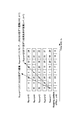
- FIG. 2 is a diagram for explaining the characteristics of the sequence group assigned to each cell.
- n s slot For example, in a cell whose cell-specific identification ID (cell ID number) is N cell ID , a sequence group having a number given by the following equation is assigned in the n s slot.
- f gh (n s) is a hopping pattern represented by the sequence group determined from PN (pseudo-random) sequence of an integer value by truncating the fractional of N cell ID / 30 as the initial value.
- N cell ID is given by an integer of 0 to 503.
- the offset f ss is an integer determined by the following equation, and is given for each cell.
- ⁇ ss is an integer from 0 to 29 that is notified to the UE as a cell-specific parameter.
- the sequence hopping pattern (f gh (n s )) is the same among 30 cells with consecutive N cell IDs , and the sequence group hopping pattern is different between cells with an N cell ID of 30 or more.
- Hopping pattern (f gh (n s)) is the same cell group is a cell cluster.
- the offset f ss is different for each cell in principle. That is, this is equivalent to using a common sequence group hopping pattern by giving a cell-specific sequence offset f ss .
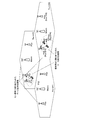
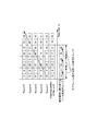
- FIG. 3 shows an example of sequence group hopping.
- a hopping pattern is common in one cell cluster, but different sequence offsets are given depending on the value of N cell ID . Therefore, different sequence groups are always used between different cells in a cell cluster. Further, hopping patterns themselves are different between different cell clusters. Therefore, even if cells in different cell clusters overlap with each other due to overlapping sequence groups, they do not continue over a plurality of slots.
- the base sequence group assigned to each cell in this way is also used for uplink SRS (sounding reference signal), which is one of the reference signals, and modulation of PUCCH, in addition to DMRS. It is done.
- uplink SRS sounding reference signal
- modulation of PUCCH in addition to DMRS. It is done.
- CoMP reception (coordinated multipoint reception) is under consideration.
- CoMP reception is a method of improving throughput by receiving a PUSCH data signal and a PUCCH control signal from a UE at a plurality of base stations (or called reception points (RP)) and combining them. It is.
- CoMP reception is particularly effective in a heterogeneous network (HetNet) environment in which a pico cell or RRH (remote radio head) having a smaller coverage is arranged in a macro cell. This is because the large interference generated between the macro cell and the pico cell, which was a problem of HetNet, can be combined as a desired signal when performing CoMP reception.
- HetNet heterogeneous network
- CoMP scenario 3 an operation of giving different N cell IDs to the macro cell and the pico cell
- CoMP scenario 4 an operation of giving the same N cell ID
- the UE uses different sequence groups depending on the connected macro cell and pico cell. At this time, if connected cells of a plurality of UEs simultaneously receiving CoMP are different and different sequence groups are used for both DMRSs, DMRSs cannot be orthogonally separated, and channel estimation accuracy deteriorates due to interference. .
- FIG. 6 is a diagram for explaining an example when a base sequence that is not a base sequence group assigned to a cell by some UEs is used in a HetNet environment.
- UEs using base sequence groups assigned to cells are not displayed, and only UEs using base sequences that are not so are displayed.
- no good method for assigning such base sequences has yet been found.
- the object of the present invention is to increase the accuracy of processing due to interference of reference signals (degradation of channel estimation accuracy for DMRS, degradation of channel quality estimation accuracy for SRS) in one cell.
- An object of the present invention is to provide a terminal device, a base station device, and a communication method that can secure a large number of signal sequences that can be used by a UE.
- the reference signals of a plurality of sequence groups are determined in advance corresponding to a plurality of sequence numbers, and are common to each cell within one cell cluster and differ between the plurality of cell clusters.
- a terminal device that wirelessly communicates with a base station in a communication system to which the sequence number assigned with an offset different from that of other cells belonging to the same cell cluster and time-varying according to a hopping pattern is provided.
- a sequence determination unit that determines the sequence number in a pattern different from an allocation pattern of the sequence number allocated to an existing cell; a reference signal generation unit that generates a reference signal of a sequence group corresponding to the determined sequence number; A radio transmission unit that transmits the generated reference signal to a base station, and the sequence determination unit is assigned to a cell in which the own device exists.
- the sequence number is a cell unique sequence number, and a variable offset that changes regularly according to time and does not continue with the same value is added to the cell unique sequence number, so that the cell unique sequence number does not always overlap A configuration for determining the sequence number is adopted.
- reference signals of a plurality of sequence groups are determined in advance corresponding to a plurality of sequence numbers, and are common to a plurality of cell clusters in each cell cluster.
- a base station apparatus in a communication system to which the sequence number that is time-varying with a different hopping pattern and is assigned with a sequence number that is different from another cell belonging to the same cell cluster is received, and receives a radio signal from a terminal apparatus A reception unit; and a signal extraction unit that extracts the reference signal from the received radio signal, and the reference signal extracted by the signal extraction unit is assigned to a cell in which the own device is present.
- the number is a cell unique sequence number, and a variable offset that changes regularly according to time and does not continue the same value is added to the cell unique sequence number.
- a constant has been the sequence number, a configuration in which the reference signal transmitted from the terminal device in correspondence with the sequence number which does not overlap at all times and the cell-specific sequence number is included.
- reference signals of a plurality of sequence groups are determined in advance corresponding to a plurality of sequence numbers, and are common to each cell in one cell cluster and differ between the plurality of cell clusters.
- a communication method in a communication system to which the sequence number assigned with an offset different from other cells belonging to the same cell cluster and time-varying according to a hopping pattern is assigned, and the communication method is assigned to a cell in which the own device exists.
- the present invention it is possible to secure a large number of signal sequences that can be used by the UE in one cell without increasing the result of channel estimation accuracy or channel quality estimation accuracy resulting from reference signal interference.
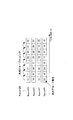
- the figure which shows the sub-frame structure of PUSCH to which normal cyclic prefix was applied The figure explaining the characteristic of the sequence group allocated to each cell
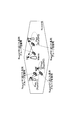
- the figure explaining an example of sequence group hopping showing an operation example of CoMP scenario 3
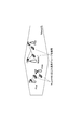
- Explanatory drawing showing an operation example of CoMP scenario 4
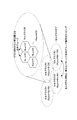
- the functional block diagram which shows the principal part of RP of embodiment of this invention The block diagram which shows the detail of RP of embodiment of this invention
- the functional block diagram which shows the principal part of the terminal device of embodiment of this invention The block diagram which shows the detail of the terminal device of embodiment of this invention
- the figure which shows the sequence group allocated by the signaling for each terminal in Embodiment 3 The figure which shows the sequence group allocated by the signaling for each terminal in Embodiment 6
- the communication system is configured to include a plurality of RPs 10 that are distributed and arranged at a number of points, and a plurality of terminal devices 20 that freely move in various places.
- RP10 is arrange
- the present embodiment can be applied in the same manner even in the case of CoMP scenario 3 in which different cell IDs are assigned to not only macro cells but also RPs 10 arranged.
- the communication system includes one or a plurality of RPs 10 in the macro cell and the terminal device 20 if attention is paid only to the periphery of one terminal device 20.
- the plurality of RPs 10 are connected by a low-delay large-capacity interface such as an optical fiber.
- the RP 10 may be a macro base station that covers a macro cell range or a pico base station that covers a pico cell range.
- the RP 10 may be a receiver that is connected to a network and used for uplink reception.
- the terminal device 20 and the RP 10 that performs PUSCH transmission / reception are determined from each other by a prior handover process and a prior control process.
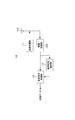
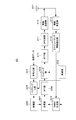
- FIG. 7 is a functional block diagram showing the main part of the RP 10 according to the embodiment of the present invention.
- the RP 10 includes an antenna 101, a radio reception unit 104 that receives a radio signal via the antenna 101, a reference signal extraction unit 12 that extracts DMRS from the reception signal, and an extraction And a received signal processing unit 13 that extracts received data from the data signal using the DMRS. Further, the RP 10 includes a transmission processing unit 11 that converts transmission data into a signal for wireless transmission and wirelessly transmits the signal via the antenna 101.
- the reference signal extraction unit 12 extracts the DMRS of this signal sequence from the radio signal.
- the reference signal extraction unit 12 extracts the DMRS according to the other sequence group from the radio signal. To do. This other sequence group assignment method will be described in detail later.
- the received signal processing unit 13 performs channel estimation from the extracted DMRS, and extracts received data from the signal received from the terminal device 20 using the channel estimation result.
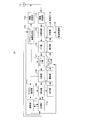
- FIG. 8 is a block diagram showing details of the RP 10 according to the embodiment of the present invention.
- the RP 10 includes an antenna 101, a radio transmission unit 102, a scheduling information generation unit 103, a radio reception unit 104, a CP removal unit 105, an FFT unit 106, Mapping unit 107, separation unit 108, equalization unit 109, inter-RP IF (inter-PR interface) 110, channel estimation unit 111, control unit 112, IDFT unit 113, demodulation unit 114, descrambling unit 115, a decoding unit 116, a determination unit 117, and a retransmission control unit 118.
- the RP 10 receives the PUSCH data signal and the PUCCH control signal transmitted from the terminal.
- the CP removal unit 105, the FFT unit 106, the demapping unit 107, and the separation unit 108 function as the reference signal extraction unit 12 in FIG.
- the decoding unit 116, the determination unit 117, and the retransmission control unit 118 function as the reception signal processing unit 13 in FIG.
- the scheduling information generation unit 103 and the wireless transmission unit 102 function as the transmission processing unit 11 in FIG.
- the control unit 112 sends the base sequence information used for DMRS and the scramble sequence information used for data scrambling to the channel estimation unit 111 and the descrambling unit 115, respectively. Specifically, the control unit 112 performs the following processing.
- the control unit 112 generates a base sequence used for DMRS multiplexed on the PUSCH data signal transmitted by the terminal device 20 and sends the base sequence to the channel estimation unit 111.
- the base sequence used in the terminal device 20 is assigned to a cell or assigned by individual terminal signaling is determined in advance by the network and notified to the terminal device 20.
- the network indicates the entire network in which all the RPs 10 and a plurality of control devices that control the communication system are connected by wire.
- This notification may be performed by the RP 10 or another RP 10 connected to the network.
- this notification may be notified as terminal-specific RRC (Radio Resource Control) control information or may be included in a MAC (Media Access Control) header.
- this notification may be notified by a control signal (PDCCH) transmitted on the downlink.
- the terminal device 20 may be notified only when the base sequence is individually assigned, and when the notification is not performed, the base sequence assigned to the cell may be used.
- the RP 10 When the base sequence assigned by terminal-specific signaling is the sequence determined and notified by the RP 10, the RP 10 notifies this information to the other RP 10 via the inter-RP IF 110. On the other hand, when the other RP 10 is determined and notified, the RP 10 receives this information from the other RP 10 via the inter-RP IF 110. Therefore, the control unit 112 can know the base sequence used in the terminal device 20.
- control unit 112 generates a scramble sequence used for data scrambling and sends it to the descrambling unit. Whether the scramble sequence to be used is assigned to a cell or assigned by terminal-specific signaling is determined in advance by the network and notified to the terminal device 20. This determination and notification may be performed by the RP 10 or another RP 10 connected to the network. Further, this notification may be notified as terminal-specific RRC (Radio Resource Control) control information, or may be included in the MAC header. Or you may notify by the control signal (PDCCH) transmitted by a downlink. In addition, when there is no notification in particular, the terminal device 20 uses the scramble sequence assigned to the cell.
- RRC Radio Resource Control
- the RP 10 When the scramble sequence signaled for each terminal is a sequence determined and notified by the RP 10 to the terminal device 20, the RP 10 notifies the other RP 10 via the inter-RP IF 110. On the other hand, when the other RP 10 is a scramble sequence determined and notified to the terminal device 20, the RP 10 receives the information from the other RP 10 via the inter-RP IF 110. Therefore, the control unit 112 can know the scramble sequence used for data scrambling.
- the scheduling information generation unit 103 instructs the terminal device 20 to include the PUSCH bandwidth and frequency position in the control signal (PDCCH) via the wireless transmission unit 102 and the antenna 101.
- the determination of bandwidth and frequency position is called frequency mapping.
- the frequency mapping instruction may be performed by the RP 10 or by another RP 10 connected to the network.
- the scheduling information generation unit 103 When the information of the frequency mapping is information determined and notified to the terminal device 20 by the RP 10, the scheduling information generation unit 103 notifies the RP 10 of the information via the inter-RP IF 110. On the other hand, when the information is determined and notified by the other RP 10 to the terminal device 20, the scheduling information generating unit 103 receives the information from the other RP 10 via the inter-RP IF 110.
- the scheduling information generation unit 103 sends the frequency mapping information to the demapping unit 107.
- the wireless reception unit 104 receives the PUSCH data signal transmitted from the terminal via the antenna, and performs reception processing such as down-conversion and A / D conversion.
- CP removal section 105 removes PUSCH DMRS and CP (Cyclic Prefix) added to the data signal, and sends the signal after removal to FFT section 106.
- the FFT unit 106 applies FFT (Fast Fourier Transform) to the DMSCH of PUSCH and the data signal, converts the signal into a frequency domain signal, and then sends the converted signal to the demapping unit 107.
- FFT Fast Fourier Transform
- the demapping unit 107 demaps the input frequency domain PUSCH according to the scheduling information.
- the demultiplexing unit 108 demultiplexes the time-multiplexed DMRS and the data signal from the PUSCH signal input from the demapping unit 107, and sends them to the channel estimation unit 111 and the equalization unit 109, respectively.
- the channel estimation unit 111 performs channel estimation using the base sequence information input from the control unit 112 and the received DMRS input from the separation unit 108. Channel estimation section 111 then sends the channel estimation result to equalization section 109.
- the equalization unit 109 performs the following processing.
- the equalization unit 109 equalizes the data signal input from the separation unit 108 using the channel estimation result input from the channel estimation unit 111. This may be performed individually by each RP 10 participating in reception, or channel estimation results and data signals obtained by a plurality of RPs 10 are transmitted and received via the inter-RP IF 110, and a single RP 10 among the RPs 10 participating in reception. May go.
- the equalization unit 109 transmits and receives the output of the separation unit 108 via the inter-RP IF 110 and aggregates the results into one of the RPs 10 participating in reception. .
- the equalization unit 109 is aggregated. Further, equalization is performed using a plurality of channel estimation results and a plurality of received data signals.
- the equalization unit 109 of a single RP10 among the RP10 participating in reception obtains an equalized output.
- the equalization unit 109 outputs the equalized output signal to the IDFT unit 113.
- the IDFT unit 113 converts the equalized frequency domain data signal into a time-domain data symbol sequence, and sends the data symbol sequence to the demodulation unit 114.
- the demodulation unit 114 performs data demodulation on the input signal, obtains a bit sequence, and outputs the bit sequence to the descrambling unit 115.
- the descrambling unit 115 descrambles the input bit sequence from the demodulation unit 114 based on the scramble sequence information input from the control unit 112. Then, the descrambled bit sequence is output to decoding section 116.
- the decoding unit 116 performs error correction decoding on the input bit sequence and outputs the decoded bit sequence to the determination unit 117.
- the determination unit 117 performs error detection on the input bit series. Error detection is performed using CRC bits added to the bit sequence. If there is no error in the CRC bit determination result, the determination unit 117 extracts the received data and notifies the retransmission control unit 118 of ACK (Acknowledgement). On the other hand, if the CRC bit determination result has an error, determination section 117 notifies NACK (Negative Acknowledgment) to retransmission control section 118.
- NACK Negative Acknowledgment
- the retransmission control unit 118 performs retransmission control on the bit sequence data signal in which an error is detected.
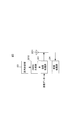
- FIG. 9 is a functional block diagram illustrating a main part of the terminal device 20 according to the embodiment of this invention.
- terminal apparatus 20 generates DMRS using antenna 201, sequence determination unit 22 that determines a sequence group used to generate DMRS, and the determined sequence group.
- DMRS generator 203 that performs transmission
- a transmission processing unit 23 that generates a signal for wireless transmission from transmission data and the generated DMRS and performs wireless transmission.
- the terminal device 20 includes a reception processing unit 24 that receives a radio signal transmitted from the RP 10 and extracts received data.
- sequence determination unit 22 determines this sequence group as a sequence group for generating a DMRS. On the other hand, when it is instructed to use a sequence group different from that assigned to the cell, sequence determination unit 22 determines this other sequence group as a sequence group for generating DMRS. The method for determining another sequence group and an instruction to use which will be described later.
- the DMRS generation unit 203 generates a DMRS of the sequence group determined by the sequence determination unit 22 and sends it to the transmission processing unit 23.
- the transmission processing unit 23 maps transmission data and the generated DMRS to resource blocks to generate a transmission signal, and wirelessly transmits the transmission signal via the antenna 201.
- FIG. 10 is a block diagram showing details of the terminal device 20 according to the embodiment of the present invention.
- the terminal device 20 includes an antenna 201, a control unit 202, a DMRS generation unit 203, an encoding unit 204, a scramble unit 205, a modulation unit 206, and a multiplexing unit. 207, a DFT unit 208, a mapping unit 209, an IFFT unit 210, a CP adding unit 211, a wireless transmission unit 212, a wireless reception unit 213, and a scheduling information extraction unit 214.
- the terminal device 20 transmits a PUSCH data signal and a PUCCH control signal to the RP 10.
- control unit 202 functions as the sequence determination unit 22 in FIG.
- the control unit 202 also includes a function unit (corresponding to a standard sequence determination unit) that determines a signal sequence to be used in DMRS from a sequence group assigned to a cell.
- a function unit corresponding to a standard sequence determination unit
- the encoding unit 204, the scramble unit 205, the modulation unit 206, the multiplexing unit 207, the DFT unit 208, the mapping unit 209, the IFFT unit 210, the CP addition unit 211, and the wireless transmission unit 212 are used as the transmission processing unit 23 in FIG. Function.
- the wireless reception unit 213 and the scheduling information extraction unit 214 function as the reception processing unit 24 in FIG.
- the control unit 202 outputs the base sequence information used for DMRS and the scramble sequence information used for data scrambling to the DMRS generation unit 203 and the scramble unit 205, respectively. Specifically, the control unit 202 performs the following processing.
- the control unit 202 outputs a base sequence used for DMRS multiplexed on the PUSCH to the DMRS generation unit 203. Whether the base sequence to be used is assigned to a cell or assigned by individual terminal signaling is previously notified to the terminal device 20 from the network. Note that if not particularly notified, the terminal device 20 may use a base sequence assigned to a cell.
- the control unit 202 generates a scramble sequence used for data scrambling and outputs it to the scramble unit 205. Whether the scramble sequence to be used is assigned to a cell or assigned by terminal-specific signaling is notified in advance from the network to the terminal device 20. When there is no notification, the control unit 202 generates a scramble sequence assigned to the cell.
- Encoding section 204 adds CRC bits to the bit sequence of the transmission data input from the upper configuration, performs error correction encoding, and outputs the codeword bit sequence to scramble section 205.
- the scramble unit 205 scrambles the codeword bit sequence using the scramble sequence input from the control unit 202. Then, the scramble unit 205 sends the result after scrambling to the modulation unit 206.
- Modulation section 206 performs data modulation on the input bit sequence and sends the modulated data signal to multiplexing section 207.
- the scheduling information extraction unit 214 first receives a downlink control signal (PDCCH) via the antenna 201 and the wireless reception unit 213, and obtains the PUSCH bandwidth and frequency position indicated by the network. These bandwidths and frequency positions are called frequency mapping information. Then, the scheduling information extraction unit 214 sends the obtained frequency mapping information to the mapping unit 209 and the DMRS generation unit 203.
- PDCCH downlink control signal
- DMRS generation section 203 uses the base sequence input from control section 202 to generate a DMRS having a sequence length corresponding to the PUSCH bandwidth input from scheduling information extraction section 214 and inputs the DMRS to multiplexing section 207. .
- the multiplexing unit 207 time-multiplexes the data signal input from the modulation unit 206 and the DMRS input from the DMRS generation unit to form a subframe, and sends the signal of this subframe to the DFT unit 208.
- the DFT unit 208 applies DFT (Discrete Fourier Transform) to the input signal to obtain a frequency domain signal.
- DFT unit 208 sends this frequency domain signal to the mapping unit 209.
- the mapping unit 209 maps the input frequency domain signal according to the frequency mapping information input from the scheduling information extraction unit 214, and sends the mapped signal to the IFFT unit 210.
- the IFFT unit 210 applies IFFT (Inverse Fourier Transform) to the input signal, obtains a time domain signal, and outputs it to the CP adding unit 211.
- IFFT Inverse Fourier Transform
- CP adding section 211 adds a CP (Cyclic Prefix) to the input data signal and DMRS, and outputs the result to radio transmitting section 212.
- the wireless transmission unit 212 performs transmission processing such as D / A conversion and up-conversion, and transmits a PUSCH signal to the RP 10 via the antenna 201.
- Step 1 Prior to transmission / reception of PUSCH, the network notifies the terminal device 20 whether the base sequence used for DMRS is assigned to a cell or is assigned by individual terminal signaling. This notification is transmitted to the control unit 202.
- Step 2 When it is instructed to use the base sequence group assigned to the cell, the control unit 202 determines to adopt the base sequence group given by Equation (1).
- DMRS generation section 203 receives the instruction from control section 202 and generates a DMRS for this sequence group. If there is no specific instruction from the network, a DMRS is generated using the base sequence group given by Equation (1).
- control unit 202 determines to adopt the base sequence group given by the following equation (3).
- DMRS generation section 203 receives the instruction from control section 202 and generates a DMRS for this sequence group.
- f ss ⁇ (n s ) is a sequence offset amount that varies depending on the value of n s (0 to 19), and has the following characteristics.
- X represents the total number of elements of the set of values that the variable x can take
- Pr represents the probability of satisfying the expression in parentheses.
- variables and functions with tilde symbols in mathematical expressions are represented by adding “ ⁇ ” next to the alphabet symbols.
- F (n s ) represents a time fluctuation component (corresponding to a fluctuation offset) of the series offset.
- the sequence number u ⁇ assigned by terminal-specific signaling is a value obtained by adding the time variation component F ( ns ) of the variation offset to the sequence number u allocated to the cell with the modulo of 30 (formula (1), (See (3)). Accordingly, a cell in which sequence number u assigned to a cell and sequence number u ⁇ assigned by terminal-specific signaling overlap is determined by the value of F ( ns ).
- the expression of the first stage of the simultaneous equations of Expression (4) indicates a condition that F ( ns ) does not become zero modulo 30.
- this expression represents a condition that the sequence number u ⁇ assigned by terminal-specific signaling does not always overlap with the sequence number u assigned to the cell in which the terminal device 20 exists.
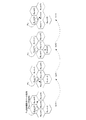
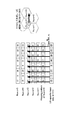
- FIG. 11 shows the state of interference between the base sequence group given by equations (3) and (4) and the sequence group assigned to the cell.
- the value of ⁇ ss in equation (2) is 0 in any cell, but D ss may be set to an arbitrary value.
- These macrocells belong to the same cell cluster, and the sequence group hopping pattern is common.
- the arrows extending from the base sequence group usage point Pu given by the equations (3) and (4) are the base sequence group and the base sequence group (cell-specific base sequence group assigned to the cell indicated by the arrow). Represents an overlap.
- Step 3 The terminal device 20 time-multiplexes the generated DMRS and the separately generated data signal to form a subframe, and maps the PUSCH signal according to the frequency mapping information instructed by the RP 10. Then, this signal is transmitted to RP10.
- Step 4 In RP10, the DMRS and the data signal are separated from the received signal of PUSCH. Thereafter, in RP10, channel estimation is performed using DMRS.
- the RP 10 equalizes the data signal based on the channel estimation result.
- This equalization includes a method of independently equalizing with a plurality of RPs 10 participating in reception, and a method of aggregating received signals from a plurality of RPs 10 participating in reception and equalizing them collectively.
- the equalization results are aggregated into any RP10, and the aggregated RP10 performs demodulation and decoding processing of received data.
- the channel estimation result and the received data signal are aggregated into one of the RPs 10, and the aggregated RPs 10 perform equalization and synthesis. Thereafter, the RP 10 demodulates and decodes the received data.
- the terminal device 20 and the RP 10 of the first embodiment can use a sequence group different from the sequence group assigned to the cell. Therefore, many sequence groups that can be used by the terminal device 20 in one macro cell can be secured.
- sequence group assigned by terminal-specific signaling is always different from the sequence group assigned to the macro cell in which the terminal device 20 exists. Therefore, DMRS does not interfere with other terminal apparatuses 20 using the cell specific sequence group in the same macro cell.
- a sequence group assigned by terminal-specific signaling overlaps with a sequence group assigned to another macro cell, this overlap does not occur continuously in the same macro cell. Further, overlapping macro cells are distributed for each time slot in the same cell cluster. Therefore, DMRS interference does not continue in a relatively nearby cell. Therefore, in the RP 10 of each cell, the accuracy of channel estimation does not deteriorate significantly due to DMRS interference.
- an offset component F ( ns ) that varies with time is added to the formula of a sequence group assigned to each cell, and a sequence group assigned to the terminal device 20 by individual signaling is added. It is determined. Therefore, if this F ( ns ) is regular, the hopping pattern of the sequence group used in the terminal device 20 and the hopping pattern of other cell clusters will not be the same or similar. Therefore, in each cell of another relatively distant cell cluster, a cell having overlapping series groups is not biased to one cell. In other words, even if cells in other cell clusters have consecutively overlapped series groups, such overlap does not occur over a long period. Therefore, in each RP 10 of another cell cluster, the accuracy of channel estimation does not deteriorate significantly due to DMRS interference.
- an existing base sequence group can be reused, and a new base sequence group or a new base sequence group can be reused.
- the sequence group allocated by terminal-specific signaling can be determined simply by adding one parameter F ( ns ) to the determination formula of the sequence group allocated to each cell. Therefore, the circuit scale for determining these sequence groups does not increase.
- the base sequence group assigned by terminal-specific signaling is characterized by sequence offsets f ss (n s ) of the following equation (5).
- the base sequence group number u ⁇ assigned by terminal-specific signaling is determined by equation (3).
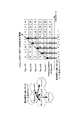
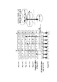
- FIG. 13 shows the allocation pattern of the base sequence group when the parameter z is changed.
- FIG. 14 shows the allocation pattern of the base sequence group when the parameter ⁇ is changed.
- FIGS. 13 and 14 show that the base sequence group of each cell overlapping the arrow line and the base sequence group assigned by terminal-specific signaling overlap in each time slot.
- the terminal device 20, and the RP 10 of the second embodiment the same effect as that of the first embodiment can be obtained only by adding a time-varying component of a simple linear function to the sequence offset. Can do.
- the sequence groups assigned by terminal-specific signaling in a plurality of cells belonging to the same cell cluster are not always overlapped. You can also. Therefore, DMRS interference does not occur between a plurality of terminal devices 20 respectively present in a plurality of cells to which these assignments are performed.
- the parameter z and the parameter ⁇ for each cell it is possible to set so that the above-described series groups overlap only at a predetermined ratio.
- the series offset f ss showed an example an arrangement for adding a linear function of time slot n s, if they meet the condition of formula (4), time-series offset f ss polynomial such as secondary function of slot n s, or may be applied a configuration of adding the various functions.
- the configuration in which the sequence offset f ss ⁇ (n s ) including the time-varying component is obtained by calculation processing has been described as an example.
- a sequence offset f ss ⁇ (n s ) For example, a configuration in which the data is stored in the storage unit as a data table and the control unit 202 reads out the data from the storage unit may be employed.
- the base sequence group allocation pattern by terminal-specific signaling is made to correspond to the DMRS OCC multiplex transmission scheme, and the other configurations are the same as those of the first embodiment. Therefore, only different points will be described in detail.
- PUSCH by multiplying two DMRSs existing in a subframe by [+1, +1] or [+1, ⁇ 1] as orthogonal codes (OCC), two different terminal apparatuses 20 can receive the same series of DMRSs. Can be code-multiplexed and transmitted. However, in this transmission method, each terminal apparatus 20 needs to use DMRS of the same series in two time slots of a subframe.
- OFC orthogonal codes
- LTE-A Rel. 10 a mechanism for stopping hopping of a base sequence group by a terminal-specific RRC control signal is provided, and DMRS transmission using OCC multiplexing can be adopted by stopping popping.
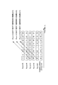
- FIG. 15 is an explanatory diagram of a sequence group assigned by terminal-specific signaling in the third embodiment.
- a configuration is adopted in which base sequence groups are assigned by adding sequence offsets of different formulas.
- such allocation can be realized as follows. That is, it is possible to employ a configuration in which a sequence number is obtained by adding a sequence offset of the following equation (6) between an odd time slot and an even time slot.
- the communication system of the third embodiment it is possible to perform DMRS transmission using OCC multiplexing between the two terminal devices 20 using the base sequence group assigned by terminal-specific signaling.
- the base sequence group assigned to the cell changes in slot units. Therefore, a sequence group assigned by terminal-specific signaling does not continuously overlap with a sequence group assigned to a cell in the same macro cell. Therefore, also in the base sequence group assignment method of the third embodiment, the DMRS of the terminal device 20 to which the sequence group is assigned by terminal-specific signaling causes interference to the DMRS of the terminal device 20 to which the cell-specific sequence group is assigned. This can be suppressed to the same level as in the first and second embodiments.
- sequence offsets f ss (n s ) including time-varying components are stored in the storage unit as a data table and read out from the storage unit. .
- whether the base sequence group hopping allocated to each terminal is a pattern that changes for each time slot or a pattern that changes for each subframe according to the next control parameter. You may switch.
- either “dmrs-WithOCC-Activated” or “grouphopping Disabled” control parameters can be used.
- the terminal device 20 changes for each subframe using a sequence offset such as Equation (6) or Table 1.
- the OCRS multiplexed DMRS is generated by adopting the hopping pattern.
- the control parameter of either “dmrs-WithOCC-Activated” or “grouphopping Disabled” is “False”
- the terminal device 20 uses the sequence offset shown in Embodiment 2 to change hopping that changes for each time slot.
- a DMRS is generated using a pattern.
- the communication system, the terminal device 20 and the RP 10 according to the fourth embodiment are configured such that the network determines a base sequence group allocation pattern performed by terminal-specific signaling and notifies the terminal device 20 of the allocation pattern.
- the configuration is the same as in the second embodiment. Hereinafter, different points will be described in detail.
- the communication system according to the fourth embodiment includes one or more RPs 10 in the macro cell and the terminal device 20.
- the network determines in advance parameters “ ⁇ , z” in Expression (5) or Expression (6) representing a base sequence group assigned by terminal-specific signaling.
- the control unit 112 of the RP 10 outputs the parameters “ ⁇ , z” to the channel estimation unit 111.
- the parameters “ ⁇ , z” are determined in advance by the network and notified to the RP 10 via the inter-RP IF 110.
- the determination of the parameters “ ⁇ , z” may be performed by the RP 10.
- the RP 10 is determined, the information is notified to the other RP 10 via the inter-RP IF 110.
- the RP 10 receives the information from the other RP 10 via the inter-RP IF 110.
- the control unit 202 of the terminal device 20 inputs the parameters “ ⁇ , z” to the DMRS generation unit 203.
- the parameters “ ⁇ , z” are determined in advance by the network and notified to the terminal device 20. This notification may be notified as terminal-specific RRC control information, or may be included in the MAC header. Or you may notify by the control signal (PDCCH) transmitted by a downlink. Unless otherwise notified, the parameters “ ⁇ , z” are both “0” (corresponding to using a base sequence group assigned to a cell).
- the processing flow related to DMRS transmission performed by the RP 10 and the terminal device 20 is the same as that of the first embodiment.
- the network appropriately sets the parameters “ ⁇ , z” in accordance with the cell arrangement, thereby setting the sequence group suitable for the cell arrangement. be able to. Specifically, in the network, a sequence group assigned by terminal-specific signaling is determined by the terminal device 20 so that sequence groups do not overlap with other cells in the vicinity where the influence of interference becomes large. Can be controlled.
- the network or RP10 does not have a configuration for notifying parameter information that can represent all possible values and combinations as parameters “ ⁇ , z”, and a bit length that can represent only some combinations of parameters “ ⁇ , z”. It is good also as a structure which notifies small parameter information. With this configuration, the number of transmission bits required for notification of the parameters “ ⁇ , z” can be reduced.
- an area of 9 bits or more of the established control data is defined as a notification area for performing terminal-specific signaling, and a base sequence group used by the terminal device 20 to generate a DMRS is determined based on information in the notification area. It is good also as a structure to determine. Specifically, when a value indicating a cell ID (for example, 0 to 503 for 9 bits) is indicated in the notification area, the terminal device 20 uses the N cell ID in the expressions (1) and (2). DMRS is generated using a base sequence group that is rewritten with a value corresponding to information in the notification area.
- a DMRS is generated using a base sequence group given by Equation (3) (for example, Equations (5) and (6)). . You may comprise in this way. Even in such a configuration, when the information in the notification area is not notified, the terminal device 20 can generate the DMRS using the base sequence group assigned to the cell.
- a base sequence group to be used is selected from a base sequence group assigned to a connected cell, a base sequence group assigned to another cell that is not connected, and a base sequence group assigned to each terminal. be able to.
- a configuration is adopted in which the parameter “ ⁇ , z” is associated with a value other than the cell ID in the notification area, and the parameter “ ⁇ , z” is notified to the terminal device 20 by a value other than the cell ID. May be.
- a value indicating other than the cell ID of the notification area for example, 504 to 511 for 9 bits
- this value is notified
- the control unit 202 of the terminal device 20 overwrites the parameter “ ⁇ , z” in Expression (5) (or Expression (6)).
- DMRS is produced
- the network can select parameters “ ⁇ , z” suitable for cell arrangement and notify the terminal device 20 without adding a new notification bit.
- the notification area is described as 9 bits or more, but the notification area may be less than 9 bits.
- a cell-specific base sequence group of another cell is allocated as a base sequence group allocated by terminal-specific signaling, in order to suppress the influence of interference, the same base sequence group as that of a neighboring cell should be avoided.
- the allocation of base sequence groups of other cells in the same cell cluster to individual terminals may increase the influence of interference. Therefore, the number of base sequence groups allocated to other cells that can actually be used as a base sequence group specific to the terminal is smaller than the number of all cell IDs “504”. Therefore, the cell ID of the assignable cell-specific base sequence group can be notified with the number of notification bits smaller than 9. For example, the offset of the connected cell with respect to the cell ID can be notified with a number of notification bits smaller than 9, and the cell ID of another cell can be notified.
- This configuration can reduce the number of bits of notification information.
- Embodiment 4 of the first to exemplary embodiments as a function of the sequence offset f ss-time slot n s.
- sequence offset f ss is a fixed value, a function of the PN hopping pattern f gh ⁇ time slot n s.
- the sequence number u ⁇ is determined by equation (7).
- Y is the total number of values that the variable y can take.
- a different value is assigned to the sequence number u ⁇ .
- f gh ⁇ (n s ) may be given as a value stored in the storage unit as a data table instead of a function.
- sequence offset f ss ⁇ including the time variation components shown in Embodiment 4 of the first to exemplary embodiments and (n s), the hopping pattern f gh ⁇ given by a function of time slot n s of the (n s)
- the sequence number u ⁇ may be determined by adding the above.
- both the PN hopping pattern and sequence offsets to be both a function of time slot n s may be configured to be provided by the data table.
- the sixth embodiment solves the problem of securing a large number of base sequence groups that can be used by the terminal device 20 in the connected cell when the influence of interference with other cells does not become so large.
- FIG. 16 is a diagram for explaining a sequence group assigned by terminal-specific signaling in the sixth embodiment.
- Embodiment 6 using the formulas (1) and (2) for determining the cell-specific base sequence group, the value of N cell ID in this is changed to the value (constant value) of the new parameter K, A sequence group assigned by terminal-specific signaling is determined.
- the value of the new parameter K is the N cell ID of a cell other than the connected cell in the same cell cluster.
- the new parameter K may be determined by the network and notified from the RP 10 to the terminal device 20.
- the seventh embodiment solves the problem of securing a large number of base sequence groups that can be used by the terminal device 20 in a connected cell when the influence of interference with cells of other cell clusters does not become so large. is there.
- FIG. 17 is a diagram illustrating a sequence group assigned by terminal-specific signaling in the seventh embodiment.
- Embodiment 7 using the formulas (1) and (2) for determining the cell-specific base sequence group, the value of N cell ID is changed to the value (constant value) of the new parameter K, A sequence group assigned by terminal-specific signaling is determined.
- the value of the new parameter K is the N cell ID of a cell in another cell cluster.
- a base sequence group assigned by terminal-specific signaling always overlaps with a cell-specific base sequence group of one cell in another cell cluster, but is random with a cell-specific base sequence group of each cell in the same cell cluster. Duplicate.
- a large number of base sequence groups that can be used in one cell can be secured by allocating base sequence groups by terminal-specific signaling using the new parameter K. This is useful when it is known that interference from a specific cell in another cell cluster hardly causes an influence, such as when a specific cell in another cell cluster is very far away.
- the new parameter K may be determined by the network and notified from the RP 10 to the terminal device 20.
- the sequence group hopping pattern itself is different from the base sequence group assigned to a cell belonging to another cell cluster. Overlap with base sequence groups assigned to other cells in the same cell cluster should not be concentrated on a single cell.
- DMRS Downlink Reference Signal
- SRS or other reference signals can also be targeted as a reference signal.
- the antenna described in the above embodiment can be replaced with an antenna port.
- each functional block used in the description of the above embodiment is typically realized as an LSI which is an integrated circuit. These may be individually made into one chip, or may be made into one chip so as to include a part or all of them.
- the name used here is LSI, but it may also be called IC, system LSI, super LSI, or ultra LSI depending on the degree of integration.
- the method of circuit integration is not limited to LSI, and may be realized by a dedicated circuit or a general-purpose processor.
- An FPGA Field Programmable Gate Array
- a reconfigurable processor that can reconfigure the connection and setting of circuit cells inside the LSI may be used.
- the present invention can be applied to a cellular mobile phone, its base station, and its communication method.
Landscapes
- Engineering & Computer Science (AREA)
- Signal Processing (AREA)
- Computer Networks & Wireless Communication (AREA)
- Mobile Radio Communication Systems (AREA)
- Digital Transmission Methods That Use Modulated Carrier Waves (AREA)
Abstract
Description


[通信システムの概要]
本実施の形態の通信システムは、多数の地点に分散配置される複数のRP10と、各地を自由に移動する複数の端末装置20とを含んで構成される。複数のRP10は、各マクロセルがUEの移動範囲のほぼ全域を覆うように、多数の地点に配置される。各マクロセルには、504通りのセルID(Ncell ID=0~503)が付与され、30個ずつ連なったマクロセルがグループ化されて複数のセルクラスタを構成する。なお本実施の形態は、マクロセルだけでなく配置されたRP10それぞれに対して異なるセルIDを付与するCoMPシナリオ3の場合でも、全く同様にして適用できる。
図7は、本発明の実施の形態のRP10の主要部を示す機能ブロック図である。
図9は、本発明の実施の形態の端末装置20の主要部を示す機能ブロック図である。
次に、DMRSの伝送に関連する処理フローをステップ1~5で説明する。


実施の形態2の通信システムでは、端末個別のシグナリングで行われるベース系列グループの割当てパターンのみが実施の形態1と異なる。従って、異なる点のみ詳細に説明する。

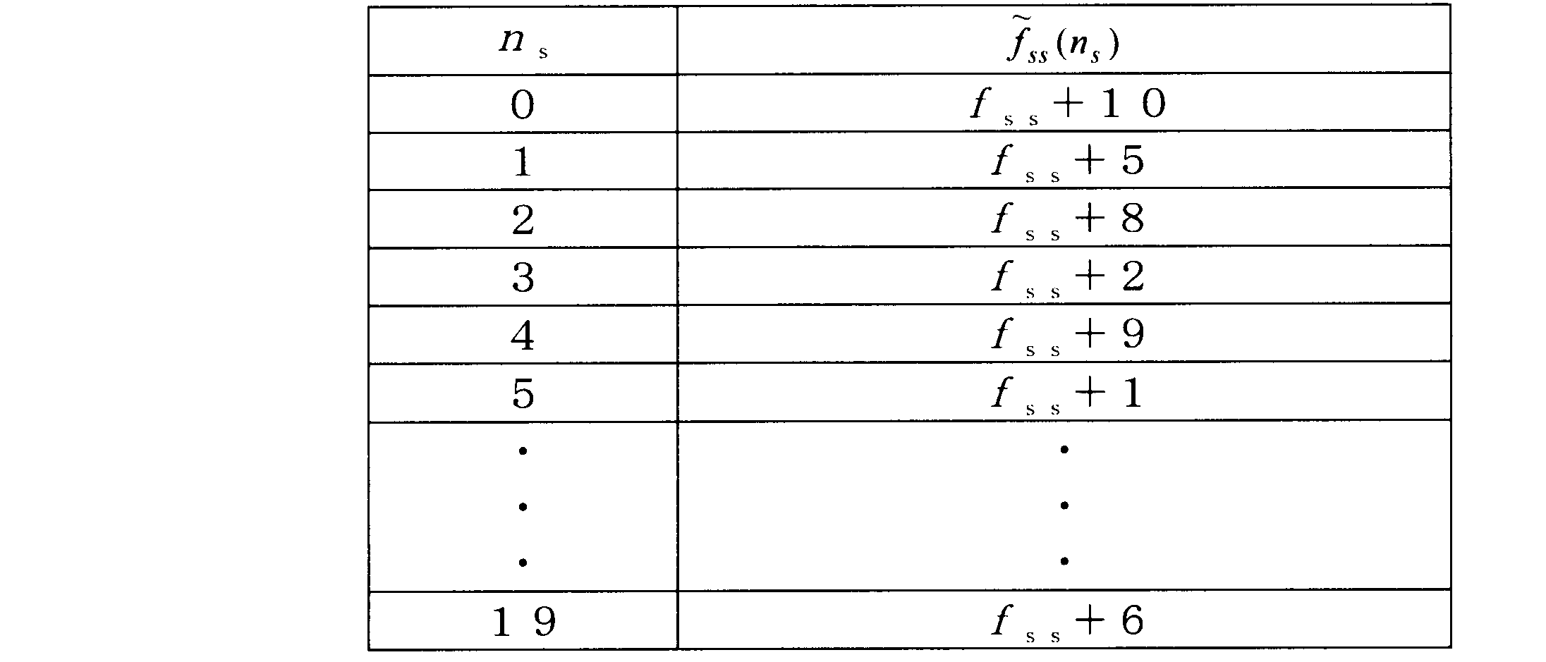
実施の形態3の通信システムでは、端末個別のシグナリングによるベース系列グループの割当てパターンを、DMRSのOCC多重伝送方式に対応させたものであり、その他の構成は実施の形態1と同様である。従って、異なる点のみ詳細に説明する。

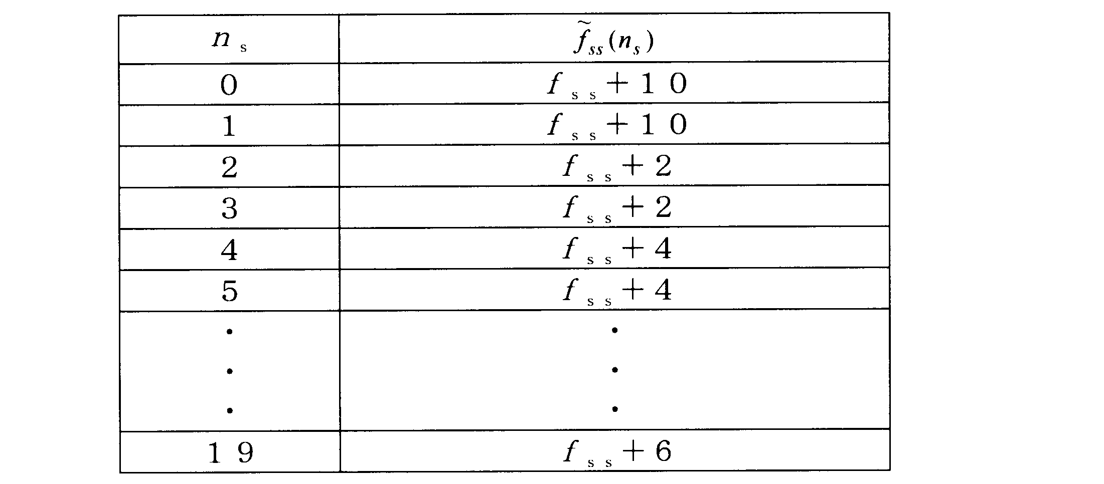
実施の形態4の通信システム、端末装置20およびRP10は、端末個別のシグナリングで行われるベース系列グループの割当てパターンを、ネットワークが決定し、端末装置20へ通知する構成としたものであり、その他の構成は、実施の形態2と同様である。以下、異なる点について詳細に説明する。
実施の形態4の通信システムは、実施の形態1と同様、マクロセル内の1つまたは複数のRP10と、端末装置20とを含んで構成される。実施の形態4の通信システムでは、端末個別のシグナリングで割り当てられるベース系列グループを表わす式(5)または式(6)のパラメータ「λ、z」を、予めネットワークが決定する。
RP10の制御部112は、パラメータ「λ、z」を、チャネル推定部111へ出力する。パラメータ「λ、z」はあらかじめネットワークで決定され、RP間IF110経由でRP10に通知されている。パラメータ「λ、z」の決定は、当該RP10が行ってもよい。当該RP10が決定した場合、その情報をRP間IF110経由で他のRP10に通知する。一方、他のRP10が決定した場合、当該RP10は、その情報をRP間IF110経由で他のRP10から受信する。
端末装置20の制御部202は、パラメータ「λ、z」を、DMRS生成部203へと入力する。パラメータ「λ、z」は予めネットワークで決定され、端末装置20に通知される。この通知は、端末個別のRRC制御情報として通知されても良いし、MACヘッダに含めても良い。あるいは下り回線で送信される制御信号(PDCCH)で通知されても良い。なお、特に通知されない場合は、パラメータ「λ、z」は共に「0」とする(セルに割り当てられたベース系列グループを用いることに相当)。
実施の形態4の通信システムでは、ネットワークから端末装置20に対して新しいパラメータ「λ、z」が通知された場合、端末装置20の制御部202は式(5)(または式(6))のパラメータ「λ、z」を上書きする。また、ネットワークは端末装置20に対して新しいパラメータ「λ、z」を通知した場合、受信に参加する各RP10の制御部112にパラメータ「λ、z」を通知し、RP10の制御部112は式(5)(または式(6))のパラメータ「λ、z」を上書きする。
以下、端末個別のシグナリングにより割り当てられるベース系列グループの決定方法について、その他の例を説明する。
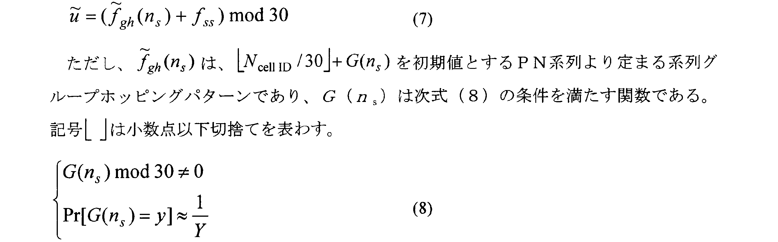
実施の形態6は、他セルとの干渉による影響が余り大きくならない場合に、接続セル内で端末装置20が使用できるベース系列グループの数を多く確保するという課題を解決するものである。
実施の形態7は、他のセルクラスタのセルとの干渉による影響が余り大きくならない場合に、接続セル内で端末装置20が使用できるベース系列グループの数を多く確保するという課題を解決するものである。
2.他のセルクラスタに属するセルに割り当てられたベース系列グループとは、系列グループのホッピングパターンそのものが異なること
3.同一セルクラスタの他のセルに割り当てられたベース系列グループとの重複が、単一のセルに偏重しないこと
11 送信処理部
12 基準信号抽出部
13 受信信号処理部
101 アンテナ
102 無線送信部
104 無線受信部
111 チャネル推定部
112 制御部
20 端末装置
22 系列決定部
23 送信処理部
24 受信処理部
201 アンテナ
202 制御部
203 DMRS生成部
212 無線送信部
213 無線受信部
Claims (15)
- 複数の系列グループの基準信号が複数の系列番号に対応して予め定められ、各セルに、1つのセルクラスタ内で共通で複数のセルクラスタ間で異なるホッピングパターンによって時間変化し、且つ、同一のセルクラスタに属する他のセルと異なるオフセットが付加された前記系列番号が割り当てられる通信システムで、基地局と無線通信する端末装置であって、
自機が存在するセルに割り当てられる前記系列番号の割当パターンと異なるパターンで前記系列番号を決定する系列決定部と、
前記決定された系列番号に対応する系列グループの基準信号を生成する基準信号生成部と、
前記生成された基準信号を基地局へ送信する無線送信部と、
を具備し、
前記系列決定部は、
自機が存在するセルに割り当てられる前記系列番号をセル固有系列番号として、前記セル固有系列番号に、時間に応じて規則的に変化し且つ同じ値が続かない変動オフセットを付加して、前記セル固有系列番号と常に重ならない前記系列番号を決定する、
端末装置。 - 前記系列番号がNSGを法とする整数で表わされるものとして、
前記変動オフセットは、次式(1)~(3)の関係を満たす、
F(ns) mod NSG ≠ 0 (1)
Pr[F(ns) = x] ≦ 3/X (2)
X ≧ 0.5 × NTS (3)
ここで、nsは、時間スロット、
NSGは、前記複数の系列グループの個数、または、1つのセルクラスタに属するセルの個数、
F(ns)は、時間スロットnsにおける前記変動オフセットの値、
Xは、前記変動オフセットの値xとして実際に取られる全ての値の集合の要素個数、
NTSは、前記系列番号の割り当てが巡回的に繰り返される1巡回期間の時間スロット数である、
請求項1記載の端末装置。 - 前記変動オフセットF(ns)は、次式で表わされる、
F(ns) = λ・ns + z (4)
ここで、λおよびzは、式(1)~(3)を満たす0以外の整数である、
請求項2記載の端末装置。 - 自機が存在するセルへの割当パターンに従って前記系列番号を決定する標準系列決定部をさらに具備し、
前記基準信号生成部は、前記系列決定部または前記標準系列決定部により決定された前記系列番号に従って前記基準信号を生成する、
請求項3記載の端末装置。 - 基地局から送られる制御情報から前記λおよび前記zの指定情報を抽出する情報抽出部をさらに具備し、
前記系列決定部は、前記抽出された前記λおよび前記zの指定情報に基づいて前記系列番号を決定する、
請求項3記載の端末装置。 - 各時間スロットにおける前記変動オフセットの値が記憶された記憶部を具備し、
前記系列決定部は、前記記憶部の値を用いて前記系列番号を決定する、
請求項2記載の端末装置。 - 前記系列決定部は、
連続する2つの時間スロットで同一の値となるように前記系列番号を決定する、
請求項2記載の端末装置。 - 前記系列決定部は、
連続する2つの時間スロットにおける同一系列グループの2つの前記基準信号を用いて2つの端末装置の前記基準信号を直交符号多重して送信する多重送信モードに移行した場合に、連続する2つの時間スロットで同一の値となるように前記系列番号を決定し、
前記多重送信モード以外の場合に、連続する2つの時間スロットで同一の値にするという制限を解除して前記系列番号を決定する、
請求項2記載の端末装置。 - 基地局から送られる制御情報からセル識別番号を表わすことのできる所定ビットの通知情報を抽出する情報抽出部をさらに具備し、
前記通知情報にセル識別番号が示されている場合に、前記標準系列決定部が、前記セル識別番号のセルへの割当パターンに準じて前記系列番号を決定する一方、
前記通知情報にセル識別番号以外の値が示されている場合に、前記系列決定部が前記系列番号を決定する、
請求項4記載の端末装置。 - 前記セル識別番号は0~503の整数であり、
前記通知情報は9ビットの情報であり、
前記通知情報の値が前記セル識別番号以外を表わす場合に前記通知情報によって前記λおよび前記zが示され、
前記系列決定部は、前記通知情報により示された前記λおよび前記zに基づいて前記系列番号を決定する、
請求項9記載の端末装置。 - 前記セル識別番号は0~503の整数であり、
前記通知情報は9ビット未満のビット情報であり、
前記通知情報の一部の範囲の値によって全ての前記セル識別番号のうちの一部が表わされ、
前記通知情報の前記一部の範囲以外の値によって前記セルへの割当パターンと異なる前記系列番号の決定を指示する情報が表わされる、
請求項9記載の端末装置。 - 複数の系列グループの基準信号が複数の系列番号に対応して予め定められ、各セルに、1つのセルクラスタ内で共通で複数のセルクラスタ間で異なるホッピングパターンによって時間変化し、且つ、同一のセルクラスタに属する他のセルと異なるオフセットが付加された前記系列番号が割り当てられる通信システムで、基地局と無線通信する端末装置であって、
自機が存在するセルに割り当てられる前記系列番号の割当パターンと異なるパターンで前記系列番号を決定する系列決定部と、
前記決定された系列番号に対応する系列グループの基準信号を生成する基準信号生成部と、
前記生成された基準信号を基地局へ送信する無線送信部と、
を具備し、
前記系列決定部は、次の1~3の条件を満たすように前記系列番号を決定する、
1.自機が存在するセルに割り当てられる前記系列番号をセル固有系列番号として、自機で決定される前記系列番号が前記セル固有系列番号と常に重ならない
2.前記ホッピングパターンが自機が存在するセルクラスタ以外の全セルクラスタの各ホッピングパターンと異なる
3.自機が存在するセルクラスタ内における自機が存在するセル以外の複数のセルを近隣セルとして、前記系列番号の割り当てが巡回的に繰り返される1巡回期間に、前記複数の近隣セルの各々に割り当てられる前記系列番号と、自機で決定される前記系列番号とで重なる回数が、前記複数の近隣セルの間で偏らない
端末装置。 - 前記3の条件は、前記複数の近隣セル間における前記系列番号の重なる回数の最大差が、前記系列番号の割り当てが巡回的に繰り返される1巡回期間で3回以下となるという条件である、
請求項12記載の端末装置。 - 複数の系列グループの基準信号が複数の系列番号に対応して予め定められ、各セルに、1つのセルクラスタ内で共通で複数のセルクラスタ間で異なるホッピングパターンによって時間変化し、且つ、同一のセルクラスタに属する他のセルと異なるオフセットが付加された前記系列番号が割り当てられる通信システムにおける基地局装置であって、
端末装置から無線信号を受信する受信部と、
前記受信された無線信号から前記基準信号を抽出する信号抽出部と、
を具備し、
前記信号抽出部が抽出する前記基準信号には、
自機が存在するセルに割り当てられる前記系列番号をセル固有系列番号として、前記セル固有系列番号に、時間に応じて規則的に変化し且つ同じ値が続かない変動オフセットを付加して決定された前記系列番号であって、前記セル固有系列番号と常に重ならない前記系列番号に対応させて前記端末装置から送信された前記基準信号が含まれる、
基地局装置。 - 複数の系列グループの基準信号が複数の系列番号に対応して予め定められ、各セルに、1つのセルクラスタ内で共通で複数のセルクラスタ間で異なるホッピングパターンによって時間変化し、且つ、同一のセルクラスタに属する他のセルと異なるオフセットが付加された前記系列番号が割り当てられる通信システムにおける通信方法であって、
自機が存在するセルに割り当てられる前記系列番号をセル固有系列番号として、前記セル固有系列番号に、時間に応じて規則的に変化し且つ同じ値が続かない変動オフセットを付加して、前記セル固有系列番号と常に重ならない前記系列番号を端末装置が決定し、
前記決定された系列番号に対応する系列グループの基準信号を前記端末装置が生成し、
前記生成された基準信号を前記端末装置が基地局へ送信し、
前記送信された基準信号を前記基地局が受信する、
通信方法。
Priority Applications (4)
| Application Number | Priority Date | Filing Date | Title |
|---|---|---|---|
| US14/006,642 US9913260B2 (en) | 2012-01-30 | 2013-01-16 | Terminal device, base station device, and communication method |
| JP2013535976A JP6065285B2 (ja) | 2012-01-30 | 2013-01-16 | 無線通信端末、通信方法及び集積回路 |
| EP13744118.4A EP2811802B1 (en) | 2012-01-30 | 2013-01-16 | Terminal device and communication method for transmitting reference signals |
| US15/874,201 US10455571B2 (en) | 2012-01-30 | 2018-01-18 | Terminal device, base station device, and communication method |
Applications Claiming Priority (2)
| Application Number | Priority Date | Filing Date | Title |
|---|---|---|---|
| JP2012016414 | 2012-01-30 | ||
| JP2012-016414 | 2012-01-30 |
Related Child Applications (2)
| Application Number | Title | Priority Date | Filing Date |
|---|---|---|---|
| US14/006,642 A-371-Of-International US9913260B2 (en) | 2012-01-30 | 2013-01-16 | Terminal device, base station device, and communication method |
| US15/874,201 Continuation US10455571B2 (en) | 2012-01-30 | 2018-01-18 | Terminal device, base station device, and communication method |
Publications (1)
| Publication Number | Publication Date |
|---|---|
| WO2013114798A1 true WO2013114798A1 (ja) | 2013-08-08 |
Family
ID=48904850
Family Applications (1)
| Application Number | Title | Priority Date | Filing Date |
|---|---|---|---|
| PCT/JP2013/000162 Ceased WO2013114798A1 (ja) | 2012-01-30 | 2013-01-16 | 端末装置、基地局装置および通信方法 |
Country Status (4)
| Country | Link |
|---|---|
| US (2) | US9913260B2 (ja) |
| EP (1) | EP2811802B1 (ja) |
| JP (3) | JP6065285B2 (ja) |
| WO (1) | WO2013114798A1 (ja) |
Cited By (1)
| Publication number | Priority date | Publication date | Assignee | Title |
|---|---|---|---|---|
| CN107431935A (zh) * | 2015-04-10 | 2017-12-01 | 松下电器(美国)知识产权公司 | 基站、终端、接收方法以及发送方法 |
Families Citing this family (6)
| Publication number | Priority date | Publication date | Assignee | Title |
|---|---|---|---|---|
| WO2015135167A1 (en) | 2014-03-13 | 2015-09-17 | Empire Technology Development Llc | Cell id allocation in heterogeneous network |
| CN108111444A (zh) * | 2017-11-17 | 2018-06-01 | 中兴通讯股份有限公司 | 信号加扰、解扰方法及装置 |
| EP3648365A1 (en) * | 2018-11-02 | 2020-05-06 | Panasonic Intellectual Property Corporation of America | Mobile terminal and base station involved in downlink control channel operations |
| WO2020220176A1 (zh) * | 2019-04-28 | 2020-11-05 | 华为技术有限公司 | 通信方法和装置 |
| US11368263B2 (en) * | 2019-08-14 | 2022-06-21 | Qualcomm Incorporated | Group hopping enhancement for base sequences |
| KR20220042929A (ko) * | 2020-09-28 | 2022-04-05 | 삼성전자주식회사 | 무선 통신 시스템에서 단말의 송신 전력 제어 방법 및 장치 |
Family Cites Families (11)
| Publication number | Priority date | Publication date | Assignee | Title |
|---|---|---|---|---|
| DE602008004885C5 (de) * | 2007-03-07 | 2017-04-27 | Huawei Technologies Co., Ltd. | Sequenzverteilung, verarbeitungsverfahren sowie entsprechende vorrichtung in einem kommunikationssystem |
| US8559952B2 (en) * | 2007-08-14 | 2013-10-15 | Telefonaktiebolaget Lm Ericsson (Publ) | Automated and seamless change of reporting cell identity |
| JP4606448B2 (ja) | 2007-10-01 | 2011-01-05 | 株式会社エヌ・ティ・ティ・ドコモ | ユーザ装置、送信方法及び通信システム |
| US8218663B2 (en) * | 2008-07-29 | 2012-07-10 | Texas Instruments Incorporated | Reference signal resource allocation for single user MIMO |
| WO2011121925A1 (ja) * | 2010-03-29 | 2011-10-06 | パナソニック株式会社 | 端末装置、基地局装置、パイロット送信方法、及び、伝搬路推定方法 |
| WO2011120584A1 (en) | 2010-04-01 | 2011-10-06 | Nokia Siemens Networks Oy | Sequence hopping in a communication system |
| US9065585B2 (en) * | 2010-05-13 | 2015-06-23 | Lg Electronics Inc. | Method and apparatus for generating a reference signal sequence in a wireless communication system |
| EP3319262A1 (en) * | 2011-06-30 | 2018-05-09 | Telefonaktiebolaget LM Ericsson (publ) | Method and device for handling base sequences in a communications network |
| US8693420B2 (en) * | 2011-08-10 | 2014-04-08 | Futurewei Technologies, Inc. | System and method for signaling and transmitting uplink reference signals |
| CN106941469B (zh) * | 2011-08-12 | 2020-05-19 | 瑞典爱立信有限公司 | 用于处理蜂窝网络中的参考信号的方法和装置 |
| US8811144B2 (en) * | 2011-11-04 | 2014-08-19 | Intel Corporation | User equipment (UE)-specific assignment of demodulation reference signal (DMRS) sequences to support uplink (UL) coordinated multipoint (CoMP) |
-
2013
- 2013-01-16 EP EP13744118.4A patent/EP2811802B1/en active Active
- 2013-01-16 JP JP2013535976A patent/JP6065285B2/ja active Active
- 2013-01-16 WO PCT/JP2013/000162 patent/WO2013114798A1/ja not_active Ceased
- 2013-01-16 US US14/006,642 patent/US9913260B2/en active Active
-
2016
- 2016-12-07 JP JP2016237744A patent/JP6281828B2/ja active Active
-
2018
- 2018-01-11 JP JP2018002798A patent/JP6554654B2/ja active Active
- 2018-01-18 US US15/874,201 patent/US10455571B2/en active Active
Non-Patent Citations (8)
| Title |
|---|
| "Multiplexing and channel coding (Release 10", 3GPP TS 36.212 V10.4.0, December 2011 (2011-12-01) |
| "Physical Channels and Modulation (Release 10", 3GPP TS 36.211 V10.4.0, December 2011 (2011-12-01) |
| "Physical layer procedures (Release 10", 3GPP TS 36.213 V10.4.0, December 2011 (2011-12-01) |
| CATT: "Considerations on UL RS enhancement for CoMP transmission", 3GPP TSG RAN WG1 MEETING #67, R1-113735, 18 November 2011 (2011-11-18), XP050561854 * |
| NEW POSTCOM: "Uplink reference signals for uplink CoMP", 3GPP TSG RAN WG1 MEETING #67, RL-113693, 18 November 2011 (2011-11-18), XP050561826 * |
| PANASONIC: "DMRS enhancement for UL CoMP, 3GPP TSG RAN WG1 Meeting #67, Rl-113810", DMRS ENHANCEMENT FOR UL COMP, 3GPP TSG RAN WG1 MEETING #67, R1-113810, 18 November 2011 (2011-11-18), XP050561903 * |
| PANASONIC: "UE-specific base sequence assignment for UL CoMP", 3GPP TSG RAN WG1 MEETING #68, R1- 120229, 10 February 2012 (2012-02-10), XP050562786 * |
| See also references of EP2811802A4 |
Cited By (1)
| Publication number | Priority date | Publication date | Assignee | Title |
|---|---|---|---|---|
| CN107431935A (zh) * | 2015-04-10 | 2017-12-01 | 松下电器(美国)知识产权公司 | 基站、终端、接收方法以及发送方法 |
Also Published As
| Publication number | Publication date |
|---|---|
| US20140098795A1 (en) | 2014-04-10 |
| JPWO2013114798A1 (ja) | 2015-05-11 |
| JP6554654B2 (ja) | 2019-08-07 |
| JP2017077007A (ja) | 2017-04-20 |
| US9913260B2 (en) | 2018-03-06 |
| EP2811802A4 (en) | 2015-08-19 |
| JP6281828B2 (ja) | 2018-02-21 |
| US10455571B2 (en) | 2019-10-22 |
| EP2811802B1 (en) | 2019-10-09 |
| EP2811802A1 (en) | 2014-12-10 |
| US20180146459A1 (en) | 2018-05-24 |
| JP6065285B2 (ja) | 2017-01-25 |
| JP2018082487A (ja) | 2018-05-24 |
Similar Documents
| Publication | Publication Date | Title |
|---|---|---|
| JP6554654B2 (ja) | 無線通信端末、通信方法及び集積回路 | |
| US12107622B2 (en) | Terminal and transmission method | |
| JP6856736B2 (ja) | 通信装置、通信方法、及び集積回路 | |
| JP7280414B2 (ja) | 受信機及び受信方法 | |
| JP6385421B2 (ja) | 端末及びdmrs生成方法 | |
| CN110169166B (zh) | 用于参考信号传输和接收的方法和装置 | |
| CN102792622B (zh) | 终端装置、基站装置、导频发送方法和传播路径估计方法 | |
| JP7224506B2 (ja) | 通信装置、通信方法および集積回路 | |
| KR20170020340A (ko) | 단말, 기지국, 송신 방법 및 수신 방법 | |
| US20220295525A1 (en) | Terminal, base station, transmission method, and reception method | |
| JP5027176B2 (ja) | 無線基地局装置、移動端末装置および無線アクセス方法 |
Legal Events
| Date | Code | Title | Description |
|---|---|---|---|
| ENP | Entry into the national phase |
Ref document number: 2013535976 Country of ref document: JP Kind code of ref document: A |
|
| WWE | Wipo information: entry into national phase |
Ref document number: 2013744118 Country of ref document: EP |
|
| WWE | Wipo information: entry into national phase |
Ref document number: 14006642 Country of ref document: US |
|
| 121 | Ep: the epo has been informed by wipo that ep was designated in this application |
Ref document number: 13744118 Country of ref document: EP Kind code of ref document: A1 |
|
| NENP | Non-entry into the national phase |
Ref country code: DE |