WO2013115038A1 - 電池状態検出装置 - Google Patents
電池状態検出装置 Download PDFInfo
- Publication number
- WO2013115038A1 WO2013115038A1 PCT/JP2013/051343 JP2013051343W WO2013115038A1 WO 2013115038 A1 WO2013115038 A1 WO 2013115038A1 JP 2013051343 W JP2013051343 W JP 2013051343W WO 2013115038 A1 WO2013115038 A1 WO 2013115038A1
- Authority
- WO
- WIPO (PCT)
- Prior art keywords
- battery
- complex impedance
- axis component
- abnormal
- normal
- Prior art date
- Legal status (The legal status is an assumption and is not a legal conclusion. Google has not performed a legal analysis and makes no representation as to the accuracy of the status listed.)
- Ceased
Links
Images









Classifications
-
- G—PHYSICS
- G01—MEASURING; TESTING
- G01R—MEASURING ELECTRIC VARIABLES; MEASURING MAGNETIC VARIABLES
- G01R31/00—Arrangements for testing electric properties; Arrangements for locating electric faults; Arrangements for electrical testing characterised by what is being tested not provided for elsewhere
- G01R31/36—Arrangements for testing, measuring or monitoring the electrical condition of accumulators or electric batteries, e.g. capacity or state of charge [SoC]
- G01R31/389—Measuring internal impedance, internal conductance or related variables
-
- G—PHYSICS
- G01—MEASURING; TESTING
- G01R—MEASURING ELECTRIC VARIABLES; MEASURING MAGNETIC VARIABLES
- G01R31/00—Arrangements for testing electric properties; Arrangements for locating electric faults; Arrangements for electrical testing characterised by what is being tested not provided for elsewhere
- G01R31/36—Arrangements for testing, measuring or monitoring the electrical condition of accumulators or electric batteries, e.g. capacity or state of charge [SoC]
- G01R31/367—Software therefor, e.g. for battery testing using modelling or look-up tables
-
- G—PHYSICS
- G01—MEASURING; TESTING
- G01R—MEASURING ELECTRIC VARIABLES; MEASURING MAGNETIC VARIABLES
- G01R31/00—Arrangements for testing electric properties; Arrangements for locating electric faults; Arrangements for electrical testing characterised by what is being tested not provided for elsewhere
- G01R31/36—Arrangements for testing, measuring or monitoring the electrical condition of accumulators or electric batteries, e.g. capacity or state of charge [SoC]
- G01R31/392—Determining battery ageing or deterioration, e.g. state of health
-
- G—PHYSICS
- G01—MEASURING; TESTING
- G01R—MEASURING ELECTRIC VARIABLES; MEASURING MAGNETIC VARIABLES
- G01R31/00—Arrangements for testing electric properties; Arrangements for locating electric faults; Arrangements for electrical testing characterised by what is being tested not provided for elsewhere
- G01R31/36—Arrangements for testing, measuring or monitoring the electrical condition of accumulators or electric batteries, e.g. capacity or state of charge [SoC]
- G01R31/382—Arrangements for monitoring battery or accumulator variables, e.g. SoC
- G01R31/3842—Arrangements for monitoring battery or accumulator variables, e.g. SoC combining voltage and current measurements
Definitions
- the present invention relates to a battery state detection device, and more particularly to a technique for performing a complex impedance analysis of a battery state of a secondary battery.
- Patent Document 1 in a method of measuring a discharge state of a battery having an internal impedance, a first internal impedance of the battery is measured at a first frequency, and a second internal impedance of the battery is measured at a second frequency. It is described that a difference between the first internal impedance and the second internal impedance is obtained, and a declination or argument of the difference between the internal impedances is obtained to express a declination or argument representing a state of discharge of the battery. . Moreover, it is described that the lower one of the first frequency and the second frequency is between 0.1 and 10 Hz.
- an AC voltage is applied to the secondary battery to detect an electric quantity related to the impedance of the secondary battery or an electric quantity related to the maximum output density, and the secondary battery is based on the electric quantity. It is described that the performance is determined. Further, it is described that the electric quantity is an AC impedance-related electric quantity related to an AC impedance component composed of a component that varies depending on the frequency of the AC voltage in the impedance of the secondary battery. Also, an AC voltage having a large number of frequency values within a predetermined frequency band is applied to the secondary battery, and the real axis component value and the imaginary axis component value of the impedance of the secondary battery are obtained for each frequency value.
- the electric quantity related to the impedance is calculated from the value and the imaginary axis component value. Further, it is described that the AC impedance component is calculated based on the diameter of the circular arc locus of the impedance in a two-dimensional plane having the real axis component value and the imaginary axis component value as axes.
- the above document describes that the state of the battery is detected by impedance, but the battery state is detected from the impedance of the so-called charge transfer resistance region, and the battery state is always sufficiently detected. I could not say. For example, in a nickel metal hydride battery, even if the SOC changes, the impedance of the charge transfer resistance region does not change, so the battery state cannot be estimated from the impedance of the charge transfer resistance region.
- An object of the present invention is to provide a device that can detect a battery state, in particular, normality / abnormality of a battery and a degree of deterioration of the battery with high accuracy by complex impedance analysis of the battery.
- the present invention provides a battery state detection device for detecting whether a battery is normal or abnormal, or detecting a deterioration degree of the battery, the measurement means for measuring complex impedance in the diffusion region of the battery, and the measurement means.
- a detecting means for calculating an inclination angle of a straight line or an approximate straight line connecting two or more complex impedances having different frequencies within the measured diffusion region of the battery, and whether the battery is normal or abnormal, or
- Storage means for preliminarily storing a threshold value corresponding to the tilt angle for determining the degree of battery deterioration, and the detection means uses the calculated tilt angle and a predetermined threshold value stored in the storage means.
- the battery is normal or abnormal, or the deterioration degree of the battery is detected.
- the two or more complex impedances having different frequencies are complex impedances with the same charge amount.
- the charge amount is zero or in the vicinity thereof.
- the detection means uses a two-dimensional plane having a real axis component and an imaginary axis component as axes, and a straight line or an approximate straight line connecting two or more complex impedances having different frequencies. The tilt angle is calculated.
- the present invention provides a battery state detection device for detecting whether a battery is normal or abnormal, or detecting the degree of deterioration of the battery, wherein the complex in a diffusion region of a base battery that serves as a reference when comparing the batteries is provided.
- Storage means for storing in advance each of a threshold value corresponding to the inclination angle and a threshold value corresponding to the tilt angle, The means uses the calculated distance and the tilt angle, the threshold value corresponding to the distance stored in the storage means and the threshold value corresponding to the tilt angle, or the battery is normal or abnormal, or It is characterized by detecting the deterioration degree of the battery.
- the reference complex impedance and the complex impedance measured by the measuring means are complex impedances at the same charge amount.
- the charge amount is zero or in the vicinity thereof.
- the detection means uses a two-dimensional plane having a real axis component and an imaginary axis component as an axis, and between the reference complex impedance and the complex impedance measured by the measurement means. And a tilt angle of a straight line connecting the reference complex impedance and the complex impedance measured by the measuring means is detected.
- the present invention also provides a battery state detection device for detecting whether a battery is normal or abnormal, comprising: a measurement unit that measures a complex impedance of a first frequency in a diffusion region of the battery; and the measurement unit.
- Detecting means for calculating at least one of a real-axis component, an imaginary-axis component, and a magnitude of the complex impedance of the measured complex impedance of the first frequency; and determining whether the battery is normal or abnormal
- Storage means for storing in advance a predetermined threshold value corresponding to at least one of the real axis component, imaginary axis component, and complex impedance magnitude of the complex impedance of the first frequency obtained by the measurement means, Is at least one of a real axis component, an imaginary axis component, and a complex impedance magnitude of the complex impedance of the first frequency, and the memory Whether the battery is normal or abnormal by comparing the threshold value corresponding to at least one of the real axis component, the imaginary axis component, and the
- the measurement means when the detection means detects an abnormality, the measurement means further includes a complex of a second frequency that is lower than the first frequency in the diffusion region of the battery.
- the impedance is measured, and the detection means calculates at least one of a real axis component, an imaginary axis component, and a complex impedance magnitude of the complex impedance of the second frequency measured by the measurement means, and the storage means , Corresponding to at least one of the real axis component, the imaginary axis component, and the complex impedance magnitude of the complex impedance of the second frequency obtained by the measuring means for determining whether the battery is normal or abnormal
- a predetermined threshold value is stored in advance, and the detection means has a real-axis component, an imaginary-axis component, and a complex impedance magnitude of the complex impedance of the second frequency. Is compared with the corresponding threshold value of at least one of the real axis component, the imaginary axis component, and the complex impedance magnitude of the complex impedance of the
- the measuring means measures a complex impedance when the charge amount of the battery is zero or in the vicinity thereof.
- the state of the battery can be detected with high accuracy by the complex impedance analysis of the battery, and more specifically, whether the battery to be detected is normal, abnormal, or deteriorated. Can be detected. Therefore, for example, when the battery mounted on the vehicle is accurately controlled or the battery is reused, the reuse efficiency can be improved by applying the present invention.
- FIG. 2 is a complex impedance diagram (Nyquist plot) of the battery shown in FIG. 1. It is a figure which shows the shift
- FIG. 4 is a complex impedance diagram (Nyquist plot) of the battery shown in FIG. 3. It is a figure (Nyquist plot) which shows the relationship between the inclination angle of the complex impedance of normal capacity balance, and the inclination angle of the complex impedance of capacity balance deviation. It is a complex impedance figure (Nyquist plot) at the time of connecting a plurality of cells in series. It is a graph which shows the relationship between the number of abnormal cells and an inclination angle.
- SOC charge amount
- the state of the secondary battery is detected by paying attention to the behavior in a specific frequency region among the behavior of the complex impedance of the secondary battery.
- a nickel-metal hydride battery Ni-MH battery
- the present invention is not limited to this, and for example, other alkaline batteries and non-aqueous batteries such as lithium batteries can also be used. Is available.
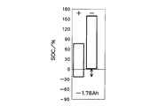
- FIG. 1 shows the positive electrode capacity and negative electrode capacity of a normal nickel metal hydride battery.
- Nickel metal hydride batteries absorb oxygen at the negative electrode during overcharge, and provide a negative electrode capacity that is larger than the positive electrode capacity so that hydrogen is not generated from the negative electrode itself (charging reserve). The rise in internal pressure is suppressed.
- a dischargeable capacity is provided in the negative electrode so that the battery capacity is not regulated by the negative electrode during discharge (discharge reserve). That is, the capacity balance between the positive electrode and the negative electrode is set so that the discharge capacity of the nickel metal hydride battery is regulated by the positive electrode capacity.
- a normal nickel metal hydride battery has a charge reserve and a discharge reserve. When attention is paid to the discharge side, the discharge reserve is positive (for example, 2.96 Ah as shown in FIG. 1).
- Fig. 2 shows the complex impedance of the equivalent circuit when an AC voltage is applied to a discharged normal battery.
- a complex impedance curve is shown.
- Equivalent circuits and complex impedances are well known and are described in, for example, Patent Document 2 described above.
- the impedance of a battery is an equivalent circuit in which a DC impedance component and an AC impedance component are connected in series.
- the AC impedance component is equivalent to a parallel circuit of a resistor and a capacitor.
- Zreal is the real axis component of the complex impedance
- Zimg is the imaginary axis component of the complex impedance
- 2 obtains the real axis component and the imaginary axis component of the complex impedance of the normal battery shown in FIG. 1, the pair data of the real axis component and the imaginary axis component, the horizontal axis represents the real axis component Zr, and the vertical axis represents the imaginary axis component.
- Zi is plotted on a two-dimensional plane (Nyquist plot: on the horizontal axis, the right side is the plus side, the left side is the minus side, and on the vertical axis, the upper side is the minus side, and the lower side is the plus side: other Nyquist plots The same).
- the region having a low frequency is a region composed of complex impedance in which material diffusion is involved, and in this embodiment is referred to as a region composed of complex impedance in the diffusion region.
- the complex impedance curve shown in FIG. 2 is composed of a curve portion (charge transfer resistance region) showing a high-frequency side arc and a substantially linear portion, but at a frequency lower than the inflection point.
- This part is a region constituted by complex impedance in the diffusion region.
- the positive electrode capacity is not significantly changed when the positive electrode capacity is 5.54 Ah to 1.54 Ah, the slope of the straight line is steep when the positive electrode capacity is 0 Ah and its vicinity.
- FIG. 3 shows a battery in which the capacity balance between the positive electrode and the negative electrode is shifted.
- the negative electrode is provided with a dischargeable capacity so that the negative electrode is not restricted during discharge.
- the capacity balance is shifted, the negative electrode has no discharge reserve and the discharge reserve is negative. (For example, as shown in FIG. 3, -1.78 Ah). That is, it becomes negative electrode regulation.
- Fig. 4 shows the complex impedance of the equivalent circuit when AC voltage is applied to the abnormal battery shown in Fig. 3.
- a complex impedance curve is shown.
- (positive electrode capacity (Ah), negative electrode capacity (Ah)) (5.56, 3.78), (4.56, 2.78), (3.56, 1.78). ), (2.56, 0.78), and (1.78, 0), the real axis component and the imaginary axis component of the complex impedance when the frequency is changed.
- the region composed of complex impedances in the diffusion region is substantially on a straight line, and there is no significant change when the negative electrode capacity is 3.78 Ah to 1.78 Ah, but the slope of the straight line is around 0 Ah negative electrode capacity. Is steep.
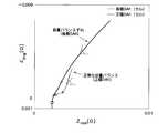
- FIG. 2 is compared with FIG. 4, there is a difference in the inclination angle of the straight line connecting two complex impedances having different frequencies in the diffusion region, and the inclination angle in the negative electrode capacity 0Ah shown in FIG. 4 is shown in FIG. The inclination angle is smaller than the positive electrode capacity 0Ah.
- FIG. 5 compares the slope in the diffusion region at the positive electrode capacity 0 Ah in the battery with the normal capacity balance in FIG. 2 with the slope in the diffusion region at the negative electrode capacity 0 Ah in the abnormal battery in FIG. Show.
- the slope when the capacity balance is shifted becomes relatively smaller than the slope when the capacity balance is normal.
- the complex impedance of the diffusion region is theoretically composed of a lumped constant region where the inclination angle is 90 deg and a distributed constant region where the inclination angle is 45 deg.
- the boundary frequency is the transition frequency. It is said. Since different mass transfer diffusion behaviors are mixed in the actual battery, the slope of the diffusion region may take a value between 45 and 90 degrees.
- the inclination angle in the diffusion region changes because the existence ratio of the high transition frequency and the low behavior changes due to the deterioration of the battery accompanying the progress of the charge / discharge cycle or the change in the state of charge of the battery. .
- the inclination in the diffusion region of the battery known to have a normal capacity balance is detected and set as a threshold value to detect the state.
- the inclination in the diffusion region of the battery to be detected is detected and compared with the threshold value to detect whether the battery is normal or abnormal, or the degree of deterioration of the battery. That is, the inclinations of both batteries are compared with each other, and when the inclination of the battery whose state is to be detected is smaller than the threshold value, it is determined that the battery is an abnormal battery with a deviated capacity balance or a deteriorated battery.
- the slope in the diffusion region can be obtained by detecting complex impedances at at least two different frequencies in the diffusion region and approximating these by linear approximation.
- the inclination of the multiple cells is the sum of the inclinations of the cells connected in series, so if at least one of the cells has an inclination smaller than the threshold, multiple cells This is because the overall inclination indicated by is expected to be smaller than the threshold value accordingly.
- Fig. 6 shows the complex impedance of each equivalent circuit when multiple cells, for example, six nickel metal hydride battery cells are connected in series and AC voltage or AC current is applied.
- a complex impedance curve is shown.
- 0 cell normal capacity balance
- 1 cell abnormal capacity balance
- 2 cells out of 6 cells have an abnormal capacity balance
- 3 cells out of 6 cells have an abnormal capacity balance
- 6 cells in the figure. Focusing on the slope in the diffusion region in each case, the slope is smaller in the case of 1 cell, 2 cells, 3 cells, and 6 cells than in the case of 0 cells.
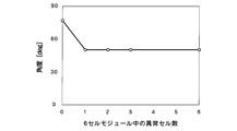
- FIG. 7 shows the relationship between the number of abnormal cells of a battery module configured by connecting six cells in series and the slope in the diffusion region.
- the horizontal axis represents the number of cells having an abnormal capacity balance among the six cells, and the vertical axis represents the inclination angle (deg) of the complex impedance in the diffusion region. If even the number of abnormal cells is included, the slope is smaller than that when no abnormal cells are included. If abnormal cells are included, the slope is almost constant regardless of the number of cells.
- a battery pack mounted on a hybrid vehicle or the like is composed of a plurality of blocks (for example, 10 blocks or more), each block is composed of a plurality of modules (for example, two modules), and each module is composed of a plurality of cells (for example, 6 blocks). ⁇ 12 cells). Therefore, when collecting and reusing a battery pack installed in an automobile, the battery pack is disassembled and disassembled into blocks or modules, and the inclination in the diffusion region is detected for each block or module. By comparing with the threshold value, it is determined whether or not at least one abnormal capacity balance cell is included in the block or module, and the block unit or module unit without disassembling the cell unit It is possible to select normal / abnormal.
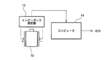
- the battery state detection device is measured by an impedance measuring instrument (or impedance analyzer) 12 which is a measuring means for measuring a complex impedance of the battery 10 by applying an AC voltage or an AC current to the battery 10 to be detected, and the impedance analyzer 12.
- the complex impedance data in the diffusion region of the battery 10 is supplied, and the computer 14 is a detection means for calculating the slope in the diffusion region from the complex impedance data.
- the computer 14 further includes a memory that is a storage unit that stores a threshold value corresponding to an inclination angle that determines whether the battery 10 is normal or abnormal or determines the degree of deterioration of the battery.
- the computer 14 compares the calculated inclination in the diffusion region with a predetermined threshold value corresponding to the calculated inclination angle stored in the memory, and determines whether the battery is normal or abnormal, or determines the degree of deterioration of the battery. Output the judgment result.
- the impedance measuring device 12 discharges the battery 10 under a predetermined condition, and then is left to stand for a predetermined time.
- two different frequencies in the diffusion region for example, 0.1 Hz of 1 Hz or less
- the impedance of the battery 10 is measured by applying an AC voltage of 0.5 Hz).
- the measurement temperature can be 25 ° C.
- the applied current can be 500 mA
- the integration time can be 2 seconds, and the like.
- the necessary complex impedance data is data at two frequencies in the diffusion region.
- the impedance measuring device 12 is not limited to this, and for example, the frequency of the applied AC voltage is sequentially changed between 1 MHz and 0.1 Hz.
- the complex impedance at each frequency may be measured.
- the value of the frequency to be measured may be appropriately set according to various conditions.
- the computer 14 includes a CPU, a memory, and an input / output interface.
- the CPU calculates the slope in the diffusion region from the impedance data obtained by the impedance measuring device 12, that is, two frequencies in the diffusion region on the two-dimensional plane of the real axis component and the imaginary axis component as shown in FIGS.
- the inclination angle of the straight line connecting the complex impedances at is calculated.
- the memory stores, as a threshold value, an inclination measured in advance with a battery showing a normal capacity balance.
- the CPU compares the threshold value stored in the memory with the inclination obtained by the calculation, and determines whether or not the inclination obtained by the calculation is smaller than the threshold value.
- the battery 10 When the calculated slope is substantially equal to the threshold value, the battery 10 is determined to be normal, and when the calculated slope is smaller than the threshold value, the battery 10 is regarded as an abnormal battery, that is, deteriorated.
- the battery is determined to be out of capacity balance and the determination result is output.
- the computer 14 may further include a display, and the determination result may be displayed on the display.
- FIG. 9 shows a processing flowchart of the present embodiment.
- the battery 10 to be detected is charged and discharged, and the amount of charge (SOC: State of Charge) is adjusted (S101). That is, the battery 10 is discharged until the SOC becomes 0% or in the vicinity thereof. “0% or the vicinity thereof” means a minute charge amount that can be regarded as 0% and substantially 0%, and means about 0% to 5%.
- SOC State of Charge
- the frequency of the alternating voltage to be applied to the battery 10 is at least two frequencies in the diffusion region, for example, 0.1 Hz and 0.5 Hz, but is not limited thereto. In general, any two frequencies below 1 Hz could be possible.
- the computer 14 calculates the inclination in the diffusion region, that is, the inclination angle of the graph (Nyquist plot) in FIG. 4 and the like using the complex impedance data at the two frequencies obtained by the impedance measuring device 12 (S103). .
- the inclination angle may be either a mathematical or graphic (geometric) method. Alternatively, if a complex impedance at a relatively high frequency of the two frequencies is a first complex impedance, and a complex impedance at a relatively low frequency is a second complex impedance, the first and second complex impedances The inclination angle of the straight line connecting is calculated.
- the computer 14 compares a threshold value (determination threshold value for determining normality / abnormality or battery deterioration degree) stored in advance in the memory with the inclination angle obtained by the calculation (S104), The normality / abnormality and the deterioration degree of the battery are determined according to the comparison result (S105). That is, if the calculated tilt angle is smaller than the threshold value, it is determined that the abnormality or the battery has deteriorated, and otherwise, it is determined that the battery is normal.
- an allowable margin may be provided for the threshold, and it may be determined that the abnormality or the battery has deteriorated only when the allowable margin is exceeded and is smaller than the threshold.
- FIG. 10 schematically shows the processing of this embodiment.
- a horizontal axis represents a real axis Zreal, and a vertical axis represents an imaginary axis Zimg, which is a complex impedance curve on a two-dimensional plane.
- Reference numeral 100 represents a complex impedance curve of a normal battery
- reference numeral 200 represents a complex impedance curve of an abnormal battery.
- the inclination angle of a straight line connecting two complex impedances having different frequencies in the diffusion region is defined as ⁇ .
- a region having two complex impedances having different frequencies in the diffusion region is defined as a region 20.
- Region 22 is an enlargement of region 20.
- the inclination angle of a straight line connecting two complex impedances having different frequencies in the diffusion region is defined as ⁇ .
- a region having two complex impedances having different frequencies in the diffusion region is defined as a region 24.
- Region 26 is an enlargement of region 24.
- FIG. 11 shows the relationship between the discharge reserve and the tilt angle. If the discharge reserve is positive, the battery has a normal capacity balance. If the discharge reserve is negative, the battery has an abnormal capacity balance. There is a positive correlation between the discharge reserve and the tilt angle in the diffusion region, and the tilt angle increases as the discharge reserve increases. Therefore, the data of the discharge reserve and the inclination angle are collected for a plurality of batteries, and the inclination angle at which the straight line obtained by linear approximation intersects the straight line of the discharge reserve 0Ah is set as a threshold value. In the figure, for example, the threshold is set to 70 deg. This threshold value is stored in advance in the memory of the computer 14.
- the discharge reserve is negative because it is smaller than the threshold value of 70 deg. That is, it can be determined that the battery has an abnormal capacity balance.
- the threshold line is set above the plot of the discharge reserve and the inclination angle so that the battery is not determined to be normal despite the negative discharge reserve, that is, the capacity balance is abnormal. is doing.
- the battery 10 is discharged to 0% or near its SOC. This is because the low SOC has a larger inclination angle, so that the normal / abnormal capacity balance can be accurately determined.
- the SOC after discharging is not limited to 0% or the vicinity thereof. For example, if it is 20% or less, it is preferable because the variation in the tilt angle is sufficiently large, and naturally a case where it is larger than 20% is also included.
- the battery whose capacity balance is shifted has been described as an example of a battery (see FIG. 3) having a negative discharge reserve (refer to FIG. 3). In addition, it is possible to appropriately detect a deviation in capacity balance.
- the inclination angle of a straight line connecting two complex impedances having different frequencies in the diffusion region is calculated, and the normal / abnormal or battery deterioration degree is determined using the inclination angle.
- a straight line connecting a reference complex impedance which is a complex impedance in the diffusion region of the base battery, which becomes a reference when comparing the batteries 10, and a complex impedance in the diffusion region of the battery 10 having the same frequency as the frequency of the reference complex impedance. It is also possible to determine whether the battery 10 is normal / abnormal or the degree of deterioration of the battery using the tilt angle.
- an embodiment in this case will be described.
- an impedance measuring instrument (or impedance analyzer) 12 that is a measuring means measures the complex impedance in the diffusion region of the battery 10 having the same frequency as the reference complex impedance.
- the computer 14 as the detection means calculates the distance between the reference complex impedance and the complex impedance measured by the measurement means, the complex impedance measured by the measurement means, and the complex impedance measured by the measurement means. The inclination angle of the connected straight line or approximate straight line is calculated.
- a memory that is a storage unit stores in advance a threshold corresponding to the distance and a threshold for the tilt angle.
- the battery 10 is normal or abnormal using the calculated distance and inclination angle, and the threshold value corresponding to the distance stored in the memory and the threshold value corresponding to the inclination angle, Alternatively, the degree of deterioration of the battery 10 is detected.
- FIG. 12 shows a processing flowchart of the present embodiment.
- the battery 10 to be detected is charged and discharged, and the SOC is adjusted (S301). That is, the battery 10 is discharged until the SOC becomes 0% or in the vicinity thereof.
- the frequency of the alternating voltage to be applied to the battery 10 is one frequency in the diffusion region, for example, 0.1 Hz, but is not limited thereto.
- the computer 14 compares the reference complex impedance, which is the complex impedance in the diffusion region of the base battery used as a reference when comparing the batteries 10, with a reference complex impedance of 0% SOC at the same frequency as the measured frequency.
- the base battery refers to, for example, the battery 10 in an initial state or a battery that is different from the battery 10 but is known to be normal.
- the inclination angle of the straight line connecting the complex impedance obtained in S302 and the reference complex impedance read from the memory and the distance between them are calculated (S303).
- the tilt angle and distance may be either mathematical or graphic (geometric).
- the reference complex impedance is measured in advance in the initial state (normal state) of the battery 10 by applying an AC voltage having the same frequency (for example, 0.1 Hz) as the measurement frequency at SOC 0%.
- an alternating voltage of the same frequency is applied to another normal battery different from the battery 10, and the complex impedance at SOC 0% is measured and stored in the memory.
- the reference complex impedance of the base battery and the complex impedance of the battery 10 to be detected are impedances measured under the same SOC and frequency.
- the complex impedance can be changed according to the SOC and the frequency. By adjusting these to the same condition, the complex impedance according to the degree of deterioration is extracted.
- the computer 14 compares a threshold value (determination threshold value for determining normality / abnormality and battery deterioration level) stored in advance in the memory with the inclination angle and distance obtained by the calculation (S304). ), Normality / abnormality and deterioration degree of the battery are determined according to the comparison result (S305). Specifically, on the two-dimensional plane of distance and angle, if the distance and angle are included in a specific range, it is determined to be normal, otherwise it is determined to be abnormal or deteriorated.
- a threshold value determination threshold value for determining normality / abnormality and battery deterioration level
- FIG. 13 schematically shows the processing of this embodiment.
- reference numeral 600 denotes a complex impedance curve in an initial state, or a complex impedance curve of another normal battery different from the battery 10, and is a complex impedance curve of a base battery.
- Reference numeral 700 denotes a complex impedance curve of the battery 10 at 0% SOC.
- Point 40 is the initial state of the battery 10 at a certain frequency, for example, 0.1 Hz or the complex impedance of another normal battery
- point 50 is the complex impedance when the battery 10 is detected at the same frequency (0.1 Hz). is there.
- the computer 14 calculates the distance A and the inclination angle B of the straight line connecting the points 40 and 50.
- FIG. 14 shows how the complex impedance changes at the same frequency when the charge amount of the base battery and the charge amount (SOC) of the battery 10 at the time of detection are different.
- FIG. 14A shows a change when the SOCs are the same
- FIG. 14B shows a change when the SOCs are different from each other.
- reference numeral 600 is a complex impedance curve of the base battery, that is, a complex impedance curve in the initial state of the battery 10, or a complex impedance curve of another normal battery
- a point 40 is a certain frequency in the diffusion region. For example, complex impedance at 0.1 Hz.
- Reference numerals 701, 702, and 703 are complex impedance curves in various deterioration states of the battery 10 to be detected, and points 51, 52, and 53 are complex impedances at the same frequency in the diffusion region, for example, 0.1 Hz. is there.
- the point 51, the point 52, and the point 53 exist in the same direction in the real axis direction and the imaginary axis direction with respect to the point 40, and the inclination angle of each straight line is in the range of 0 deg to 90 deg.
- the distance and angle change variously according to the degree of deterioration of the battery 10. For example, when the distance is larger than a certain value, it is determined as abnormal. Possible causes of abnormalities include a shift in capacity balance, a decrease in electrolyte, deterioration of the active material, and the like.
- the processing in the present embodiment uses the change in FIG.
- Reference numerals 704 and 705 are complex impedance curves in various deterioration states of the battery 10 to be detected. Complex impedance at the same frequency in the diffusion region, for example 0.1 Hz. There are straight lines connecting the points 40 and 54, and straight lines connecting the points 40 and 55, and there are distances and inclination angles of the respective straight lines.
- the complex impedance may decrease not only with respect to the point 40 but also with respect to the point 40 as with the point 54 as well as when the complex impedance changes with respect to the point 40 as in the point 55. .
- the tilt angle is not within the range of 0 deg to 90 deg, but within the range of 180 deg to 270 deg.
- the base battery and the battery 10 are basically compared under the same SOC, even if there is a slight difference between the two SOCs, it is normal by considering the change in FIG. / Abnormality can be determined. That is, when the SOC is the same, the tilt angle is in the range of 0 deg to 90 deg. However, when the SOC is slightly different, the tilt angle may be 180 deg to 270 deg. Therefore, the tilt angle is 180 deg to 270 deg. Even in this case, it is determined as normal when a predetermined condition is satisfied.
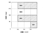
- FIG. 15 shows an example of a normal range and an abnormal range on a two-dimensional plane of distance and tilt angle.
- 4 is a threshold map stored in advance in the memory of the computer 14.
- ranges 1, 2, and 3 indicated by hatching are ranges that are determined to be abnormal
- the other range 4 is a range that is determined to be normal.
- the range 1 has a distance of 0.6 m ⁇ or more and an inclination angle of 0 deg to 90 deg. This is an abnormality caused by an increase in resistance.
- the distance is 0.2 m ⁇ or more and the inclination angle is 90 deg to 180 deg. This is an abnormality caused by the battery performance deterioration due to the change of the limit capacity.
- Range 3 the distance is 0.2 m ⁇ or more and the inclination angle is 270 deg to 360 deg. This is an anomaly caused by deterioration in battery performance due to an increase in components and liquid resistance.
- Range 4 is a range that is determined to be normal. Specifically, the tilt angle is 0 deg to 90 deg when the distance is less than 0.6 m ⁇ , the tilt angle is 180 deg to 270 deg regardless of the distance, and the tilt angle is less than 0.2 m ⁇ . Is 270 deg to 360 deg.
- the computer 14 determines that the battery 10 is abnormal and outputs the result. On the other hand, if the distance and angle obtained in S303 is within the range 4, for example. The computer 14 determines that the battery 10 is normal and outputs the result.
- the battery 10 is discharged to 0% or near its SOC. This is because a low SOC has a larger distance and angle variation, and therefore, normality / abnormality can be accurately determined.
- the SOC after discharging is not limited to 0% or the vicinity thereof. For example, if it is 20% or less, it is preferable because the variation in distance and angle is sufficiently large, and naturally a case where it is larger than 20% is also included.
- the base battery is a battery 10 in the initial state or a battery that is different from the battery 10 and is known to be normal, but in addition to these batteries, the battery 10 to be detected is compared.
- Any battery may be used as long as it is a reference battery.
- any battery that has a known state (such as SOC) to be compared with the battery 10 to be detected can be used.
- the present embodiment it is possible to detect whether the battery 10 is normal or abnormal by using the slope angles of the complex impedances at two different frequencies in the diffusion region. Moreover, it is possible to detect whether the battery 10 is normal or abnormal by using the inclination angle and distance of the complex impedance at the same frequency in the diffusion region.
- the battery pack mounted on the vehicle is removed from the vehicle and reused, it is necessary to detect whether the block or module constituting the battery pack is normal or abnormal. Using the method, it is possible to detect whether it is normal or abnormal in units of blocks or modules, and the utilization rate at the time of reuse is improved.
- normality / abnormality can be detected at normal temperature (25 ° C.) and nondestructively.
- normal temperature 25 ° C.
- FIG. 6 or FIG. 7 in the case where a plurality of cells are connected in series, even if at least one cell is abnormal, this can be reliably detected.
- the normality / abnormality can be reliably detected in units or block units composed of a plurality of modules.
- Frequency condition two different frequencies in the diffusion region
- Charge amount (SOC) condition Same charge amount (zero or near in the first embodiment)
- Detection item Inclination angle
- Detection status Whether the capacity balance is normal or abnormal (when multiple cells are connected in series, the number of cells with abnormal capacity balance can be detected by detecting the values of the real and imaginary axes. Can also be detected)
- the impedance measuring device 12 may perform a process of measuring one complex impedance different from a certain frequency in the diffusion region of the battery 10. That is, in the first embodiment, the impedance measuring device 12 does not necessarily need to measure the complex impedance at two different frequencies. Therefore, for example, in the flowchart of FIG. 9, prior to the process of S102, it is determined whether a complex impedance having a frequency within the diffusion region of the battery 10 is stored in the memory.
- the process proceeds to S102. If stored, only the complex impedance at other frequencies may be measured in the process of S102. In the second embodiment, since the reference complex impedance is stored in the memory in advance prior to the measurement of the battery 10, it is not necessary to measure with the impedance measuring instrument 12.
- the inclination angle of a straight line connecting two complex impedances having different frequencies in the diffusion region of the battery 10 is calculated, but three or more different frequencies in the diffusion region of the battery 10 are calculated. You may calculate the inclination angle of the straight line which tied complex impedance, or an approximate straight line.
- the complex impedance in the diffusion region of the battery includes the Warburg impedance and the transmission line model impedance.
- normality / abnormality is detected using the Warburg impedance, but normality / abnormality may be detected using the impedance of the transmission line model.
- the Warburg impedance is a known impedance related to hydrogen diffusion, for example, Kuriyama, N., et al .: J Alloy & Compd., 202 (1993), 183 Zhang, W., et al .: Electrochem. Soc. The 185 th Meet., (1994), abstr.No.593 Etc. are disclosed.
- Fig. 16 shows the Warburg impedance and the transmission line model impedance, respectively.
- region A is Warburg impedance
- region B is the impedance of the transmission line model.
- the inclination angle of a straight line connecting the impedances of two transmission line models having different frequencies is calculated, and the obtained inclination angle is compared with a threshold value to compare the normal / Detect anomalies.
- the complex impedance is Nyquist plotted to calculate the tilt angle.
- a Bode diagram may be used.
- the alternating voltage is applied to the measurement of complex impedance, what is necessary is just an alternating current signal, for example, you may apply an alternating current.
- the inclination angle of a straight line connecting two complex impedances having different frequencies is calculated using a two-dimensional plane with the real axis component and the imaginary axis component as axes.
- the present invention is not limited to this.
- the tilt angle may be calculated using a three-dimensional plane including the real axis component and the imaginary axis component as axes, and the Bode diagram with the frequency and the magnitude of the complex impedance as axes, and the frequency and phase.
- the tilt angle may be calculated using a Bode diagram as an axis.
- the distance between the reference complex impedance and the complex impedance measured by the measuring means is detected using a two-dimensional plane having the real axis component and the imaginary axis component as axes.
- the angle of inclination of the straight line connecting the complex impedance measured by the measurement means was detected, but the present invention is not limited to this, and the distance and angle of inclination are calculated using a three-dimensional plane including the real axis component and the imaginary axis component as axes.
- the distance and the tilt angle may be calculated using a Bode diagram with the frequency and the magnitude of the complex impedance as axes and a Bode diagram with the frequency and the phase as axes.
- FIG. 17 the real axis component and the imaginary axis component of the complex impedance are obtained, and the pair data of the real axis component and the imaginary axis component is converted into a two-dimensional plane with the horizontal axis representing the real axis component Zreal and the vertical axis representing the imaginary axis component Zimg. Plotted figure is shown (Nyquist plot: on the horizontal axis, the right side is the plus side, the left side is the minus side, and on the vertical axis, the upper side is the minus side, and the lower side is the plus side: other Nyquist plots are the same).
- the complex impedance can be broadly divided into a charge transfer resistance region II having an arc shape on the high frequency side, a diffusion resistance region III having a substantially linear shape on the low frequency side, and a component / liquid resistance region I. .
- the diffusion resistance region III is a region constituted by impedance in which substance diffusion is involved, and is a region having a frequency of about 1 Hz or less.
- the applicant of the present application has found that there is a significant difference in complex impedance between the normal capacity balance battery (FIG. 1) and the abnormal capacity balance battery (FIG. 3) in this diffusion resistance region.
- indicate absolute values of the respective values.
- FIG. 18 shows a change in complex impedance in a diffusion resistance region of a battery having a normal capacity balance and a battery having an abnormal capacity balance.
- a battery having a normal capacity balance is a battery having a positive electrode capacity of 0 at the time of discharging
- a battery having an abnormal capacity balance is a battery having a negative electrode capacity of 0 (reserved deviation) at the time of discharging. Focusing on the complex impedance at a frequency of 0.1 Hz, both the real-axis component and the imaginary-axis component of the complex impedance are remarkably increased in a battery with an abnormal capacity balance as compared with a battery with a normal capacity balance.
- an in-vehicle battery is composed of a module in which a plurality of cells are connected in series. Therefore, it is necessary to identify whether the capacity balance is normal or abnormal capacity in units of modules.
- a battery pack mounted on a hybrid vehicle or the like is composed of a plurality of blocks (for example, 10 blocks or more), each block is composed of a plurality of modules (for example, two modules), and each module is composed of a plurality of cells. (For example, 6 to 12 cells). Therefore, when collecting and reusing a battery pack mounted on an automobile, the battery pack is disassembled and disassembled into blocks or modules, and at least one abnormal operation is performed for each block or each module. It is desirable to determine whether a cell with capacity balance is included and to select normal / abnormal in block units or module units without disassembling the cells.
- FIG. 19 shows a configuration of a module configured by connecting six cells in series as a plurality of cells.
- the six cells are No. 1-No. No. 6; 1, no. 2, no. 4, no. 5 and no.
- the cell No. 6 has a normal capacity balance. Only 3 cells have an abnormal capacity balance.
- the module to be judged is a normal module, or at least one It is possible to identify whether the module is an abnormal module in which the cell capacity balance is shifted.
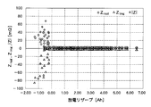
- FIG. 21 shows the relationship between the complex impedance in the diffusion region, for example, the imaginary axis component Zimg of the complex impedance at 0.1 Hz, and the minimum discharge reserve in the module.
- the horizontal axis is the imaginary axis component Zimg of the complex impedance, and the right side is the negative side.
- the minimum discharge reserve is 0 to a positive value (see FIG. 1).
- the capacity balance is shifted in at least one of the cells constituting the module
- the lowest discharge reserve in the module is a discharge reserve of the cell whose capacity balance is shifted and shows a negative value (see FIG. 3). .
- the value of the imaginary axis component of the complex impedance is almost constant in a normal module with a minimum discharge reserve of 0 to positive, but the module has an imaginary axis of complex impedance with an abnormal module with a negative minimum discharge reserve.
- the value of the component changes greatly, and the negative value of the imaginary axis component of the complex impedance tends to increase as the negative value of the discharge reserve increases. That is, in the normal module, there is no correlation between the minimum discharge reserve in the module and the value of the imaginary axis component, but in the abnormal module, there is a correlation between the minimum discharge reserve in the module and the value of the imaginary axis component. .
- a normal module and an abnormal module can also be identified by the presence or absence of such correlation.
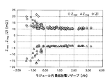
- FIG. 22 shows the relationship between the complex impedance in the diffusion region, for example, the real axis component Zreal, the imaginary axis component Zimg, and the complex impedance magnitude
- a circle indicates a real axis component Zreal
- a triangle indicates an imaginary axis component Zimg
- and a rhombus indicates a size
- are almost constant regardless of the minimum discharge reserve, but the minimum discharge reserve is negative.
- increases, and the value of the imaginary axis component Zimg decreases. Therefore, it is possible to distinguish between a normal module and an abnormal module by using the real axis component Zreal and the magnitude
- are not always changed in the region 100 near 0 although the minimum in-module discharge reserve is negative.
- the reason for this is that (1) The definition differs between the actual battery SOC and the SOC at the time of discharge reserve calculation. (2) Since the module is configured by connecting a plurality of cells in series, variation may occur in each cell.
- the above (1) indicates that when SOC is 0% at the time of discharge reserve calculation (that is, the minimum discharge reserve in the module on the horizontal axis in FIG. 22 is 0 Ah), a slightly dischargeable capacity remains in the positive electrode portion of battery SOC 0% or less. In other words, the battery SOC 0% may have “discharge reserve is positive”, but the SOC at the time of discharge reserve calculation may be “discharge reserve is negative”.
- FIG. 23 shows the relationship between the discharge reserve in cell units and the complex impedance at 0.1 Hz. As shown by the arrow 200 in the figure, it can be seen that there are cells in which the complex impedance does not change even when the discharge reserve is negative, until the discharge reserve is near -0.6 (Ah).
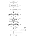
- FIG. 24 shows a processing flowchart of the present embodiment.
- the battery 10 to be detected is charged and discharged, and the amount of charge (SOC) is adjusted (S501). That is, the battery 10 is discharged until the SOC becomes 0% or in the vicinity thereof.
- “0% or the vicinity thereof” means a minute charge amount that can be regarded as 0% and substantially 0%, and means about 0% to 5%.
- the positive electrode capacity becomes 0 Ah and the negative electrode capacity remains (the discharge reserve is positive).
- the negative electrode capacity becomes 0 Ah (the discharge reserve is negative). ).
- the discharge until the SOC reaches “0% or in the vicinity thereof” can be detected even with a small reserve deviation (abnormality) in the low SOC. This is because it can be performed with high accuracy.
- the SOC after discharge is not limited to “0% or its vicinity”. For example, when only a large reserve deviation needs to be detected, it may be larger than “0% or its vicinity”.
- the measurement electrode is connected to the battery 10 and the complex impedance of the battery 10 is measured by the impedance measuring instrument 12 which is a measuring means for measuring the complex impedance of the battery 10 by applying an alternating voltage or alternating current (S502).
- the frequency of the alternating voltage to be applied to the battery 10 is a frequency in the diffusion region, for example, 0.1 Hz or 1 Hz, but is not limited thereto. In general, any frequency below 1 Hz could be possible.
- the computer 14 serving as detection means has a memory in which a threshold value for determining normality / abnormality is stored in advance, and the complex impedance data at the frequency obtained by the impedance measuring device 12 is used to increase the magnitude of the imaginary axis component Zimg
- an allowable margin may be provided for the threshold value, and it may be determined as abnormal or deteriorated only when the allowable margin is exceeded and is smaller than the threshold value. In that case, normal / abnormal may be determined more accurately by other determination methods within the allowable margin.
- the normality / abnormality of the battery can be easily detected from the complex impedance at one frequency in the diffusion region.
- the normality / abnormality of the battery is determined by comparing the imaginary axis component Zimg with a threshold value, but the imaginary axis component Zimg best reflects the abnormality (deviation) of the capacity balance.
- Zimg it is possible to suitably determine whether there is an abnormality (shift) in capacity balance.
- the real axis component Zreal in addition to the abnormality (displacement) of the capacity balance, the abnormality due to the increase in liquid resistance / component resistance is also reflected. It can be suitably determined.
- Causes of the increase in the liquid resistance and component resistance include depletion of the electrolytic solution, a decrease in electrical conductivity of the electrolytic solution due to impurities, and an increase in resistance due to component deterioration. Also, by using the complex impedance magnitude
- the module in which one cell is abnormal among the plurality of cells has been described as an example.
- normality / abnormality of a battery is detected by focusing on one frequency in the diffusion region, for example, complex impedance at 0.1 Hz, but a plurality of frequencies in the diffusion region, for example, 0. It is also possible to detect normal / abnormal battery by paying attention to the complex impedance at 1 Hz and 1 Hz. That is, the lower the frequency of the AC voltage to be applied, the greater the change in the complex impedance of the abnormal battery, and it is possible to detect normality / abnormality with high accuracy, but it takes time to detect.
- the computer 14 first detects normality / abnormality at a high frequency that can be detected in a short time although the accuracy is relatively low, and then detects normality / abnormality at a low frequency that can be detected with high accuracy. Execute the process.
- FIG. 25 shows the relationship between the real axis component Zreal, the imaginary axis component Zimg, and the complex impedance magnitude
- FIG. 22 shows a complex impedance at a frequency of 0.1 Hz
- FIG. 25 shows a complex impedance at a frequency of 1 Hz.
- an abnormal module having a negative minimum discharge reserve is used.
- the real axis component and size increase and the imaginary axis component decreases, the amount of change is relatively small compared to the case of FIG.
- the normality / abnormality can be detected quickly by comparing the magnitude of the imaginary axis component with a threshold (the threshold in this case is a threshold different from the threshold in the third embodiment). it can.
- FIG. 26 shows a processing flowchart of the present embodiment.
- the battery 10 to be detected is charged and discharged, and the amount of charge (SOC) is adjusted (S701). That is, the battery 10 is discharged until the SOC becomes 0% or in the vicinity thereof.
- “0% or the vicinity thereof” means a minute charge amount of 0% as in the first embodiment and a minute charge amount that can be regarded as substantially 0%, and means about 0% to 5%.
- the frequency of the AC voltage to be applied to the battery 10 is a frequency in the diffusion region, for example, 1 Hz, but is not limited thereto.
- the computer 14 serving as detection means has a memory for storing a threshold value for determining normality / abnormality in advance, and uses the complex impedance data at the frequency obtained by the impedance measuring device 12 to increase the magnitude of the imaginary axis component Zimg.
- is calculated and compared with a threshold value for 1 Hz (S703). If the size obtained by the calculation is not larger than the threshold value for 1 Hz, it is determined as normal (S706). On the other hand, when the magnitude obtained by the calculation is larger than the threshold value for 1 Hz, the impedance measuring device 12 does not immediately determine that there is an abnormality, but further applies an AC voltage or an AC current to the battery 10. The complex impedance of the battery 10 is measured (S704).
- the frequency of the AC voltage to be applied to the battery 10 is a frequency within the diffusion region and is lower than 1 Hz, for example, 0.1 Hz.
- the computer 14 calculates the magnitude
- the battery 10 is certainly determined to be abnormal (S207). If it is greater than the threshold value at 1 Hz, but is less than or equal to the threshold value at 0.1 Hz, it is determined to be normal at 0, 1 Hz with higher accuracy, so it is finally determined to be normal (S706).
- the battery 10 determined as NO in S703 and determined as normal does not need to be processed after S704, and can be excluded from the measurement target at 0.1 Hz, thereby reducing the total determination time. Can do.
- the imaginary axis component Zimg at 1 Hz and the imaginary axis component Zimg at 0, 1 Hz are not necessarily the same. They may be different from each other.
- Each of them may be focused and compared with a threshold value, and if any of the imaginary axis component Zimg, the real axis component Zreal, and the magnitude
- normality / abnormality of the battery 10 can be detected at normal temperature (25 ° C.) and nondestructively.
- normal temperature 25 ° C.
- a module unit composed of a plurality of cells or a plurality of modules is composed. Normal / abnormal detection can be reliably performed in block units. Therefore, when this embodiment is applied to a vehicle-mounted battery, normality / abnormality of the vehicle-mounted battery can be detected even while the vehicle is traveling, and abnormal charging / discharging of the battery can be prevented.
- normality / abnormality is detected using the Warburg impedance of the complex impedance, but normality / abnormality may be detected using the impedance of the transmission line model.
- complex impedance is Nyquist plotted, but a Bode diagram may be used.
- the normal / abnormality is detected using at least one of the real axis component Zreal, the imaginary axis component Zimg, and the complex impedance magnitude
- Z the real axis component Zreal
- Examples of these possible combinations are as follows.
- an abnormality in the battery is an abnormality in capacity balance (significantly reflected in Zimg) and an abnormality due to an increase in liquid resistance / component resistance It is also possible to specify which is largely caused by (largely reflected in Zreal).
- the value of the frequency to be measured may be appropriately set according to various conditions.
- a module in which a plurality of cells are connected in series is described.
- a real cell component, an imaginary axis component, a complex impedance is also used in a single cell.
- the state of the battery can be detected by comparing any one of the sizes with a threshold.
Landscapes
- Physics & Mathematics (AREA)
- General Physics & Mathematics (AREA)
- Secondary Cells (AREA)
- Tests Of Electric Status Of Batteries (AREA)
- Charge And Discharge Circuits For Batteries Or The Like (AREA)
Description
まず、本実施形態における基本原理について説明する。本実施形態における二次電池の状態検出装置及び方法では、二次電池の複素インピーダンスの挙動のうち、特定の周波数領域における挙動に着目して二次電池の状態を検出するものである。なお、以下の説明では二次電池としてニッケル水素電池(Ni-MH電池)を例にとり説明するが、これに限定されるものではなく、例えば他のアルカリ電池やリチウム電池等の非水系電池にも利用可能である。
Z=Vac/Iac=Zreal+jZimg
として得られる。Zrealは複素インピーダンスの実軸成分、Zimgは複素インピーダンスの虚軸成分である。図2は、図1に示す正常電池の複素インピーダンスの実軸成分及び虚軸成分を求め、実軸成分と虚軸成分のペアデータを、横軸を実軸成分Zr、縦軸を虚軸成分Ziとする二次元平面にプロットしたものである(ナイキストプロット:横軸では右側をプラス側、左側をマイナス側とし、縦軸では上側をマイナス側、下側をプラス側としている:他のナイキストプロットも同じ)。放電状態の電池に対して、(正極容量(Ah),負極容量(Ah))=(5.54,8.5)、(4.54,7.5)、(3.54,6.5)、(2.54,5.5)、(1.54,4.5)、(0.54,3.5)、(0,2.96)のそれぞれの容量において周波数を変化させたときの複素インピーダンスの実軸成分、虚軸成分である。図において、0.1Hz、1Hz、10Hz、100Hzの点を明示的に示している。具体的には、丸印が0.1Hz、菱形印が1Hz、三角印が10Hz、四角印が100Hzを示す。周波数が低い領域は、物質拡散の関与した複素インピーダンスで構成された領域であり、本実施形態においては、拡散領域における複素インピーダンスで構成された領域と称する。具体的には、図2で示す複素インピーダンス曲線は、高周波数側の円弧を示す曲線部分(電荷移動抵抗領域)と、略直線状の部分から構成されているが、その変曲点より低周波数の部分(略直線状の部分)が拡散領域における複素インピーダンスで構成される領域である。拡散領域における複素インピーダンスで構成された領域は、正極容量が5.54Ah~1.54Ahでは大きな変化はないものの、正極容量が0Ah及びその近傍では直線の傾きが急峻となっている。
図8に、本実施形態における電池状態検出装置の全体構成を示す。電池状態検出装置は、検出対象である電池10に交流電圧もしくは交流電流を印加して電池10の複素インピーダンスを測定する測定手段であるインピーダンス測定器(あるいはインピーダンスアナライザ)12と、インピーダンスアナライザ12で測定された電池10の拡散領域内における前記複素インピーダンスのデータが供給され、これら複素インピーダンスのデータから拡散領域における傾きを算出する検出手段であるコンピュータ14を有する。コンピュータ14は、さらに、電池10が正常であるか異常であるか、または前記電池の劣化度を判定する傾き角度に対応する閾値を記憶した記憶手段であるメモリを有している。そして、コンピュータ14は、算出された拡散領域における傾きとメモリに記憶した、算出された傾き角度に対応する所定の閾値と大小比較して正常か異常か、または前記電池の劣化度を判定して判定結果を出力する。
上記の第1実施形態では、拡散領域における周波数の異なる2つの複素インピーダンスを結んだ直線の傾き角度を演算し、この傾き角度を用いて正常/異常または電池の劣化度を判定しているが、電池10を比較する際に基準となるベース電池の拡散領域内の複素インピーダンスである基準複素インピーダンスと、基準複素インピーダンスの周波数と同一の周波数の電池10の拡散領域内の複素インピーダンスとを結んだ直線の傾き角度を用いて電池10の正常/異常または電池の劣化度の判定を行うこともできる。以下では、この場合の実施形態について説明する。なお、第1実施形態の測定手段の代わりに、測定手段であるインピーダンス測定器(あるいはインピーダンスアナライザ)12は、基準複素インピーダンスの周波数と同一の周波数の電池10の拡散領域内の複素インピーダンスを測定する。また、第1実施形態の検出手段の代わりに、検出手段であるコンピュータ14は、基準複素インピーダンスと測定手段で測定した複素インピーダンスとの間の距離及び基準複素インピーダンスと測定手段で測定した複素インピーダンスを結んだ直線または近似直線の傾き角度を算出する。さらに、第1実施形態の記憶手段の代わりに、記憶手段であるメモリは、距離に対応する閾値と傾き角度に対する閾値とを予め記憶する。そして、第1実施形態の検出手段の代わりに、算出された距離及び傾き角度と、メモリに記憶された距離に対応する閾値及び傾き角度に対応する閾値とを用いて電池10の正常あるいは異常、または電池10の劣化度を検出する。
周波数条件:拡散領域内の異なる2つの周波数
充電量(SOC)条件:同一充電量(第1実施形態ではゼロないしその近傍)
検出項目:傾き角度
検出状態:容量バランスが正常であるか異常であるか(複数セルが直列接続されている場合、実軸と虚軸の値を検出することで、異常な容量バランスのセル数も検出可能)
周波数条件:拡散領域内の一つの周波数
充電量条件:第2実施形態ではゼロないしその近傍
基準複素インピーダンス:電池の初期状態、あるいは正常である他の電池の複素インピーダンス(予めメモリに記憶)
検出項目:傾き角度及び距離
検出状態:容量バランスが正常であるか異常であるか
Kuriyama, N., et al. : J Alloy & Compd., 202 (1993), 183
Zhang, W., et al. : Electrochem. Soc. the 185th Meet., (1994), abstr. No.593
等に開示されている。
図17に、複素インピーダンスの実軸成分及び虚軸成分を求め、実軸成分と虚軸成分のペアデータを、横軸を実軸成分Zreal、縦軸を虚軸成分Zimgとする二次元平面にプロットした図を示す(ナイキストプロット:横軸では右側をプラス側、左側をマイナス側とし、縦軸では上側をマイナス側、下側をプラス側としている:他のナイキストプロットも同じ)。複素インピーダンスは、高周波側であって円弧形状を示す電荷移動抵抗領域IIと、低周波側であって略直線形状を示す拡散抵抗領域IIIと、部品・液抵抗領域Iに大別することができる。拡散抵抗領域IIIは、物質拡散の関与したインピーダンスで構成された領域であり、周波数が略1Hz以下の領域である。本願出願人は、この拡散抵抗領域において、正常な容量バランスの電池(図1)と異常な容量バランスの電池(図3)とで、複素インピーダンスに有意な相違が生じることを見出している。なお、本実施形態において、複素インピーダンスの大きさ|Z|、実軸成分の大きさ|Zreal|、虚軸成分の大きさ|Zimg|とは、それぞれの値の絶対値を示す。
(1)実際の電池のSOCと、放電リザーブ計算時のSOCで定義が異なる
(2)モジュールは複数セルを直列接続して構成されているため、各セルでばらつきが生じている
が考えられる。上記の(1)は、放電リザーブ計算時のSOC0%(つまり、図22横軸のモジュール内最低放電リザーブが0Ah)の場合、電池SOC0%以下の正極部分に僅かに放電可能な容量が残っており、電池SOC0%では「放電リザーブが正」でも放電リザーブ計算時のSOCでは「放電リザーブが負」になっていることもあるからと考えられる。
上記の第3実施形態では、拡散領域内における一つの周波数、例えば0.1Hzにおける複素インピーダンスに着目して電池の正常/異常を検出しているが、拡散領域内における複数の周波数、例えば0.1Hzと1Hzにおける複素インピーダンスに着目して電池の正常/異常を検出することもできる。すなわち、印加する交流電圧の周波数が低いほど、異常な電池の複素インピーダンスの変化が大きく、その分だけ高精度に正常/異常を検出することが可能であるが、検出に時間を要する。一方、印加する交流電圧の周波数が相対的に高い場合には、異常な電池の複素インピーダンスの変化は相対的に小さく、その分だけ検出の精度は低下するものの、検出に要する時間は短縮できる(1Hzの場合、0.1Hzに比べて1/10の時間で済む)。
(a)虚軸成分Zimgの値あるいはその大きさを閾値と比較する
(b)虚実成分Zimgの値あるいはその大きさを閾値と比較するとともに、実軸成分Zrealの値あるいはその大きさを閾値と比較する
(c)虚軸成分Zimgの値あるいはその大きさを閾値と比較するとともに、大きさ|Z|を閾値と比較する
(d)大きさ|Z|を閾値と比較する
(e)実軸成分Zrealの値あるいはその大きさを閾値と比較する
(f)実軸成分Zrealの値あるいはその大きさを閾値と比較するとともに、大きさ|Z|を閾値と比較する
Claims (11)
- 電池が正常あるいは異常であるか、または前記電池の劣化度を検出する電池状態検出装置であって、
前記電池の拡散領域内の複素インピーダンスを測定する測定手段と、
前記測定手段で測定した前記電池の拡散領域内の周波数の異なる2つ以上の前記複素インピーダンスを結んだ直線または近似直線の傾き角度を算出する検出手段と、
前記電池が正常であるか異常であるか、または前記電池の劣化度を判定する前記傾き角度に対応する閾値を予め記憶した記憶手段とを備え、
前記検出手段は、算出された傾き角度と前記記憶手段に記憶された所定の閾値とを用いて前記電池が正常あるいは異常であるか、または前記電池の劣化度を検出することを特徴とする電池状態検出装置。 - 請求項1記載の電池状態検出装置において、
周波数の異なる2つ以上の前記複素インピーダンスは、同一充電量での複素インピーダンスであることを特徴とする電池状態検出装置。 - 請求項2記載の電池状態検出装置において、
前記充電量はゼロないしその近傍であることを特徴とする電池状態検出装置。 - 請求項1~3のいずれかに記載の電池状態検出装置であって、
前記検出手段は、実軸成分及び虚軸成分を軸とする二次元平面を用いて、周波数の異なる2つ以上の前記複素インピーダンスを結んだ直線または近似直線の傾き角度を算出することを特徴とする電池状態検出装置。 - 電池が正常あるいは異常であるか、または前記電池の劣化度を検出する電池状態検出装置であって、
前記電池を比較する際に基準となるベース電池の拡散領域内の複素インピーダンスである基準複素インピーダンスの周波数と同一の周波数の前記電池の拡散領域内の複素インピーダンスを測定する測定手段と、
前記基準複素インピーダンスと前記測定手段で測定した前記複素インピーダンスとの間の距離及び前記基準複素インピーダンスと前記測定手段で測定した前記複素インピーダンスを結んだ直線の傾き角度を検出する検出手段と、
前記電池が正常であるか異常であるか、または前記電池の劣化度を判定する前記距離に対応する閾値と前記傾き角度に対応する閾値のそれぞれを予め記憶した記憶手段とを備え、
前記検出手段は、算出された前記距離及び前記傾き角度、前記記憶手段に記憶された前記距離に対応する閾値及び前記傾き角度に対応する閾値とを用いて前記電池が正常あるいは異常であるか、または前記電池の劣化度を検出することを特徴とする電池状態検出装置。 - 請求項5記載の電池状態検出装置において、
前記基準複素インピーダンスと前記測定手段で測定した前記複素インピーダンスは、同一充電量での複素インピーダンスであることを特徴とする電池状態検出装置。 - 請求項6記載の電池状態検出装置において、
前記充電量はゼロないしその近傍であることを特徴とする電池状態検出装置。 - 請求項5~7のいずれかに記載の電池状態検出装置であって、
前記検出手段は、実軸成分及び虚軸成分を軸とする二次元平面を用いて、前記基準複素インピーダンスと前記測定手段で測定した前記複素インピーダンスとの間の距離を検出するとともに、前記基準複素インピーダンスと前記測定手段で測定した前記複素インピーダンスとを結んだ直線の傾き角度を検出することを特徴とする電池状態検出装置。 - 電池が正常であるか異常であるかを検出する電池状態検出装置であって、
前記電池の拡散領域における第1周波数の複素インピーダンスを測定する測定手段と、
前記測定手段で測定した第1周波数の複素インピーダンスの実軸成分、虚軸成分、複素インピーダンスの大きさの少なくともいずれか1つを算出する検出手段と、
前記電池が正常であるか異常であるかを判定する前記測定手段で得られる第1周波数の複素インピーダンスの実軸成分、虚軸成分、複素インピーダンスの大きさの少なくともいずれか1つに対応する所定の閾値を予め記憶した記憶手段とを備え、
前記検出手段は、前記第1周波数の複素インピーダンスの実軸成分、虚軸成分、複素インピーダンスの大きさの少なくともいずれか1つと、前記記憶手段に記憶された第1周波数の複素インピーダンスの実軸成分、虚軸成分、複素インピーダンスの大きさの少なくともいずれか1つに対応する閾値とを比較することで前記電池が正常あるいは異常であるかを検出することを特徴とする電池状態検出装置。 - 請求項9記載の電池状態検出装置において、
前記検出手段が異常であると検出した場合には、さらに、
前記測定手段は、前記電池の拡散領域における第1周波数よりも低い周波数である第2周波数の複素インピーダンスを測定し、
前記検出手段は、前記測定手段で測定した第2周波数の複素インピーダンスの実軸成分、虚軸成分、複素インピーダンスの大きさの少なくともいずれか1つを算出し、
前記記憶手段は、前記電池が正常であるか異常であるかを判定する前記測定手段で得られる第2周波数の複素インピーダンスの実軸成分、虚軸成分、複素インピーダンスの大きさの少なくともいずれか1つに対応する所定の閾値を予め記憶しており、
前記検出手段は、前記第2周波数の複素インピーダンスの実軸成分、虚軸成分、複素インピーダンスの大きさの少なくともいずれか1つと、前記記憶手段に記憶された第2周波数の複素インピーダンスの実軸成分、虚軸成分、複素インピーダンスの大きさの少なくともいずれか1つの対応する閾値とを比較することで前記電池が正常あるいは異常を検出することを特徴とする電池状態検出装置。 - 請求項9,10のいずれかに記載の電池状態検出装置において、
前記測定手段は、前記電池の充電量がゼロないしその近傍である場合の複素インピーダンスを測定することを特徴とする電池状態検出装置。
Priority Applications (4)
| Application Number | Priority Date | Filing Date | Title |
|---|---|---|---|
| JP2013556343A JP5873113B2 (ja) | 2012-01-31 | 2013-01-23 | 電池状態検出装置 |
| US14/343,720 US9354278B2 (en) | 2012-01-31 | 2013-01-23 | Device for detecting normal, abnormal or deteriorated battery state |
| EP16151183.7A EP3032271B1 (en) | 2012-01-31 | 2013-01-23 | Battery state detection device |
| EP13744278.6A EP2811312B1 (en) | 2012-01-31 | 2013-01-23 | Battery state detection device |
Applications Claiming Priority (4)
| Application Number | Priority Date | Filing Date | Title |
|---|---|---|---|
| JP2012018745 | 2012-01-31 | ||
| JP2012-018745 | 2012-01-31 | ||
| JP2012032606 | 2012-02-17 | ||
| JP2012-032606 | 2012-02-17 |
Publications (1)
| Publication Number | Publication Date |
|---|---|
| WO2013115038A1 true WO2013115038A1 (ja) | 2013-08-08 |
Family
ID=48905080
Family Applications (1)
| Application Number | Title | Priority Date | Filing Date |
|---|---|---|---|
| PCT/JP2013/051343 Ceased WO2013115038A1 (ja) | 2012-01-31 | 2013-01-23 | 電池状態検出装置 |
Country Status (4)
| Country | Link |
|---|---|
| US (1) | US9354278B2 (ja) |
| EP (2) | EP2811312B1 (ja) |
| JP (1) | JP5873113B2 (ja) |
| WO (1) | WO2013115038A1 (ja) |
Cited By (21)
| Publication number | Priority date | Publication date | Assignee | Title |
|---|---|---|---|---|
| JP2016065832A (ja) * | 2014-09-25 | 2016-04-28 | プライムアースEvエナジー株式会社 | 電池状態判定方法及び電池状態判定装置 |
| JP2016095959A (ja) * | 2014-11-13 | 2016-05-26 | 古河電気工業株式会社 | 二次電池状態検出装置および二次電池状態検出方法 |
| JP2016152110A (ja) * | 2015-02-17 | 2016-08-22 | プライムアースEvエナジー株式会社 | 車両用の二次電池の再利用方法 |
| JP2017040574A (ja) * | 2015-08-20 | 2017-02-23 | 株式会社デンソー | 二次電池の拡散抵抗同定装置 |
| KR20180063825A (ko) * | 2016-12-02 | 2018-06-12 | 도요타 지도샤(주) | 전지 상태 추정 장치 |
| CN108627771A (zh) * | 2017-03-22 | 2018-10-09 | 丰田自动车株式会社 | 电池状态推测装置 |
| JP2019049479A (ja) * | 2017-09-11 | 2019-03-28 | プライムアースEvエナジー株式会社 | 二次電池状態判定方法及び二次電池状態判定装置 |
| JP2019061924A (ja) * | 2017-09-28 | 2019-04-18 | プライムアースEvエナジー株式会社 | 二次電池のイオン濃度推定方法及びイオン濃度推定装置 |
| JP2020021592A (ja) * | 2018-07-31 | 2020-02-06 | トヨタ自動車株式会社 | 電池情報処理システム、二次電池の容量推定方法、ならびに、組電池、および、その組電池の製造方法 |
| JP2021048018A (ja) * | 2019-09-17 | 2021-03-25 | 学校法人早稲田大学 | 電池状態推定方法および電池システム |
| JP2021048016A (ja) * | 2019-09-17 | 2021-03-25 | 学校法人早稲田大学 | 電池状態推定方法および電池システム |
| JP2021048017A (ja) * | 2019-09-17 | 2021-03-25 | 学校法人早稲田大学 | 電池状態推定方法および電池システム |
| CN113064008A (zh) * | 2021-03-25 | 2021-07-02 | 广东电网有限责任公司广州供电局 | 一种中压熔断器质量检测方法、装置、设备和介质 |
| JP2022080183A (ja) * | 2020-11-17 | 2022-05-27 | 学校法人早稲田大学 | 電池モジュール |
| JP2023175531A (ja) * | 2022-05-30 | 2023-12-12 | 一般財団法人日本自動車研究所 | 二次電池の劣化診断方法 |
| US12025676B2 (en) | 2019-08-01 | 2024-07-02 | Denso Corporation | Device for assessing degree of degradation of secondary battery and assembled battery |
| US12510601B2 (en) | 2020-06-30 | 2025-12-30 | Denso Corporation | Secondary battery deterioration degree determination device |
| US12523708B2 (en) | 2020-06-30 | 2026-01-13 | Denso Corporation | Deterioration degree determination device for secondary battery |
| CN121348121A (zh) * | 2025-12-22 | 2026-01-16 | 深圳市德兰明海新能源股份有限公司 | 数据构建方法、装置、电池包健康状态检测方法和设备 |
| WO2026034071A1 (ja) * | 2024-08-09 | 2026-02-12 | 株式会社Gsユアサ | 推定装置、推定方法及び蓄電設備 |
| US12560564B2 (en) | 2021-01-13 | 2026-02-24 | Kabushiki Kaisha Toyota Chuo Kenkyusho | Detection device, management device, and detection method |
Families Citing this family (27)
| Publication number | Priority date | Publication date | Assignee | Title |
|---|---|---|---|---|
| US10429444B2 (en) | 2012-01-31 | 2019-10-01 | Primearth Ev Energy Co., Ltd. | State of charge detection device |
| JP5744957B2 (ja) * | 2013-04-12 | 2015-07-08 | プライムアースEvエナジー株式会社 | 電池状態判定装置 |
| DE102014217135B4 (de) * | 2014-08-28 | 2025-04-30 | Volkswagen Aktiengesellschaft | Verfahren und Vorrichtung zur Bestimmung eines State-of-Charge-Wertes einer Batterie |
| US10534038B2 (en) * | 2015-06-26 | 2020-01-14 | Japan Aerospace Exploration Agency | Method and system for estimating state of charge or depth of discharge of battery, and method and system for evaluating health of battery |
| DE102016201026B4 (de) * | 2016-01-25 | 2019-03-21 | Volkswagen Aktiengesellschaft | Verfahren und Vorrichtung zur Bestimmung einer Restkapazität einer Blei-Säure-Batterie |
| JP6555212B2 (ja) * | 2016-08-15 | 2019-08-07 | トヨタ自動車株式会社 | バッテリパックの製造方法 |
| KR101972521B1 (ko) * | 2016-08-26 | 2019-04-25 | 주식회사 엘지화학 | 배터리 셀의 성능 테스트 장치 및 방법 |
| JP6672112B2 (ja) * | 2016-09-06 | 2020-03-25 | プライムアースEvエナジー株式会社 | 電池容量測定装置及び電池容量測定方法 |
| CN106842066B (zh) * | 2017-04-21 | 2019-03-08 | 惠州亿纬锂能股份有限公司 | 一种电池放电容量的检测方法和装置 |
| JP6958412B2 (ja) * | 2018-02-14 | 2021-11-02 | 株式会社デンソー | 二次電池の異常判定装置 |
| CN109975717B (zh) * | 2019-04-12 | 2021-03-19 | 苏州正力新能源科技有限公司 | 一种动力电池内阻的在线计算方法 |
| US11495976B2 (en) * | 2019-10-01 | 2022-11-08 | Samsung Sdi Co., Ltd. | Battery system and method for controlling battery system |
| US11104242B2 (en) * | 2019-10-01 | 2021-08-31 | Ford Global Technologies, Llc | Bus bar resistance identification via AC signal injection and battery control therefrom |
| KR102773613B1 (ko) * | 2019-10-07 | 2025-02-25 | 주식회사 엘지에너지솔루션 | Bms 성능 테스트 장치 및 방법 |
| CN111157911B (zh) * | 2019-12-30 | 2022-03-18 | 北京四维智联科技有限公司 | 一种电池包压差过大的预测方法、装置及设备 |
| US11977121B2 (en) | 2020-09-15 | 2024-05-07 | Analog Devices International Unlimited Company | Autonomous battery monitoring system |
| KR20220062223A (ko) | 2020-11-06 | 2022-05-16 | 현대자동차주식회사 | 차량 배터리 관리 시스템 및 방법 |
| KR102657496B1 (ko) | 2020-12-28 | 2024-04-12 | 주식회사 엘지에너지솔루션 | 배터리 관리 장치 및 방법 |
| JP7090949B1 (ja) * | 2021-05-19 | 2022-06-27 | 東洋システム株式会社 | 電池状態判定方法および電池状態判定装置 |
| WO2022261910A1 (zh) * | 2021-06-17 | 2022-12-22 | 宁德时代新能源科技股份有限公司 | 充电控制方法及装置、电池管理系统、可读存储介质 |
| WO2023219640A1 (en) * | 2021-10-08 | 2023-11-16 | University Of Houston System | Onboard circuits and methods to predict the health of critical elements |
| KR102650095B1 (ko) * | 2021-11-30 | 2024-03-21 | 주식회사 민테크 | 이차전지의 불량 검출 방법 및 장치 |
| US12282069B2 (en) * | 2022-01-13 | 2025-04-22 | GM Global Technology Operations LLC | Systems and methods for diagnosing health of a battery using in-vehicle impedance analysis |
| EP4480018A1 (en) * | 2022-02-15 | 2024-12-25 | Medtronic, Inc. | Depth of discharge determination of alkaline batteries |
| JP2024009689A (ja) * | 2022-07-11 | 2024-01-23 | 株式会社東芝 | 電池の診断方法、診断装置、診断システム及び診断プログラム |
| AU2024345923A1 (en) * | 2023-09-22 | 2026-04-16 | Fluence Energy, Llc | System and method for identifying atypical conditions in compound energy storage systems |
| KR20250072203A (ko) * | 2023-11-16 | 2025-05-23 | 에스케이온 주식회사 | 배터리 관리 시스템 및 그 제어 방법 |
Citations (5)
| Publication number | Priority date | Publication date | Assignee | Title |
|---|---|---|---|---|
| JPS60144675A (ja) | 1983-12-12 | 1985-07-31 | アスラブ・ソシエテ・アノニム | 電池の放電状態の測定方法及び装置 |
| JPH0443975A (ja) * | 1990-06-11 | 1992-02-13 | Matsushita Electric Ind Co Ltd | 鉛蓄電池の検査方法 |
| JPH04141966A (ja) * | 1990-09-29 | 1992-05-15 | Shin Kobe Electric Mach Co Ltd | 据置用鉛電池の劣化状態検出方法 |
| JPH05135806A (ja) * | 1991-05-31 | 1993-06-01 | American Teleph & Telegr Co <Att> | 蓄電池の残存容量の決定方法 |
| JP2000299137A (ja) | 1998-08-10 | 2000-10-24 | Toyota Motor Corp | 二次電池の状態判定方法及び状態判定装置、並びに二次電池の再生方法 |
Family Cites Families (7)
| Publication number | Priority date | Publication date | Assignee | Title |
|---|---|---|---|---|
| JPH0843506A (ja) | 1994-08-02 | 1996-02-16 | Nippon Telegr & Teleph Corp <Ntt> | ニッケル系電池の劣化状態検知方法 |
| JP3402167B2 (ja) | 1996-12-17 | 2003-04-28 | 松下電器産業株式会社 | 電池の状態解析装置 |
| JP4030217B2 (ja) * | 1999-03-12 | 2008-01-09 | トヨタ自動車株式会社 | 組電池の異常判定装置および異常判定方法 |
| FR2813124B1 (fr) * | 2000-08-17 | 2003-01-17 | Oldham France Sa | Procede de test d'une batterie au plomb en vue de sa charge dans des conditions optimales |
| DE102009000337A1 (de) | 2009-01-21 | 2010-07-22 | Robert Bosch Gmbh | Verfahren zur Bestimmung eines Alterungszustandes einer Batteriezelle mittels Impedanzspektroskopie |
| JP2011158444A (ja) | 2010-02-04 | 2011-08-18 | Gs Yuasa Corp | 二次電池の残存容量検出方法および装置 |
| US10429444B2 (en) | 2012-01-31 | 2019-10-01 | Primearth Ev Energy Co., Ltd. | State of charge detection device |
-
2013
- 2013-01-23 WO PCT/JP2013/051343 patent/WO2013115038A1/ja not_active Ceased
- 2013-01-23 EP EP13744278.6A patent/EP2811312B1/en active Active
- 2013-01-23 JP JP2013556343A patent/JP5873113B2/ja active Active
- 2013-01-23 EP EP16151183.7A patent/EP3032271B1/en active Active
- 2013-01-23 US US14/343,720 patent/US9354278B2/en active Active
Patent Citations (5)
| Publication number | Priority date | Publication date | Assignee | Title |
|---|---|---|---|---|
| JPS60144675A (ja) | 1983-12-12 | 1985-07-31 | アスラブ・ソシエテ・アノニム | 電池の放電状態の測定方法及び装置 |
| JPH0443975A (ja) * | 1990-06-11 | 1992-02-13 | Matsushita Electric Ind Co Ltd | 鉛蓄電池の検査方法 |
| JPH04141966A (ja) * | 1990-09-29 | 1992-05-15 | Shin Kobe Electric Mach Co Ltd | 据置用鉛電池の劣化状態検出方法 |
| JPH05135806A (ja) * | 1991-05-31 | 1993-06-01 | American Teleph & Telegr Co <Att> | 蓄電池の残存容量の決定方法 |
| JP2000299137A (ja) | 1998-08-10 | 2000-10-24 | Toyota Motor Corp | 二次電池の状態判定方法及び状態判定装置、並びに二次電池の再生方法 |
Non-Patent Citations (2)
| Title |
|---|
| KURIYAMA, N. ET AL., J ALLOY & COMPD., vol. 202, 1993, pages 183 |
| ZHANG, W. ET AL., ELECTROCHEM. SOC. THE 185TH MEET., 1994 |
Cited By (30)
| Publication number | Priority date | Publication date | Assignee | Title |
|---|---|---|---|---|
| JP2016065832A (ja) * | 2014-09-25 | 2016-04-28 | プライムアースEvエナジー株式会社 | 電池状態判定方法及び電池状態判定装置 |
| JP2016095959A (ja) * | 2014-11-13 | 2016-05-26 | 古河電気工業株式会社 | 二次電池状態検出装置および二次電池状態検出方法 |
| US10355325B2 (en) | 2015-02-17 | 2019-07-16 | Primearth Ev Energy Co., Ltd. | Method for reusing vehicle rechargeable battery |
| JP2016152110A (ja) * | 2015-02-17 | 2016-08-22 | プライムアースEvエナジー株式会社 | 車両用の二次電池の再利用方法 |
| JP2017040574A (ja) * | 2015-08-20 | 2017-02-23 | 株式会社デンソー | 二次電池の拡散抵抗同定装置 |
| KR101982938B1 (ko) * | 2016-12-02 | 2019-05-27 | 도요타 지도샤(주) | 전지 상태 추정 장치 |
| KR20180063825A (ko) * | 2016-12-02 | 2018-06-12 | 도요타 지도샤(주) | 전지 상태 추정 장치 |
| US10718817B2 (en) | 2016-12-02 | 2020-07-21 | Toyota Jidosha Kabushiki Kaisha | Battery state estimating apparatus |
| CN108627771A (zh) * | 2017-03-22 | 2018-10-09 | 丰田自动车株式会社 | 电池状态推测装置 |
| JP2019049479A (ja) * | 2017-09-11 | 2019-03-28 | プライムアースEvエナジー株式会社 | 二次電池状態判定方法及び二次電池状態判定装置 |
| US10605871B2 (en) | 2017-09-11 | 2020-03-31 | Primearth Ev Energy Co., Ltd. | Method and device for determining state of rechargeable battery |
| JP2019061924A (ja) * | 2017-09-28 | 2019-04-18 | プライムアースEvエナジー株式会社 | 二次電池のイオン濃度推定方法及びイオン濃度推定装置 |
| JP2020021592A (ja) * | 2018-07-31 | 2020-02-06 | トヨタ自動車株式会社 | 電池情報処理システム、二次電池の容量推定方法、ならびに、組電池、および、その組電池の製造方法 |
| US12025676B2 (en) | 2019-08-01 | 2024-07-02 | Denso Corporation | Device for assessing degree of degradation of secondary battery and assembled battery |
| JP2021048016A (ja) * | 2019-09-17 | 2021-03-25 | 学校法人早稲田大学 | 電池状態推定方法および電池システム |
| JP2021048018A (ja) * | 2019-09-17 | 2021-03-25 | 学校法人早稲田大学 | 電池状態推定方法および電池システム |
| JP7194384B2 (ja) | 2019-09-17 | 2022-12-22 | 学校法人早稲田大学 | 電池状態推定方法および電池システム |
| JP7194383B2 (ja) | 2019-09-17 | 2022-12-22 | 学校法人早稲田大学 | 電池状態推定方法および電池システム |
| JP7261477B2 (ja) | 2019-09-17 | 2023-04-20 | 学校法人早稲田大学 | 電池状態推定方法および電池システム |
| JP2021048017A (ja) * | 2019-09-17 | 2021-03-25 | 学校法人早稲田大学 | 電池状態推定方法および電池システム |
| US12523708B2 (en) | 2020-06-30 | 2026-01-13 | Denso Corporation | Deterioration degree determination device for secondary battery |
| US12510601B2 (en) | 2020-06-30 | 2025-12-30 | Denso Corporation | Secondary battery deterioration degree determination device |
| JP7727986B2 (ja) | 2020-11-17 | 2025-08-22 | 国立大学法人東海国立大学機構 | 電池モジュール |
| JP2022080183A (ja) * | 2020-11-17 | 2022-05-27 | 学校法人早稲田大学 | 電池モジュール |
| US12560564B2 (en) | 2021-01-13 | 2026-02-24 | Kabushiki Kaisha Toyota Chuo Kenkyusho | Detection device, management device, and detection method |
| CN113064008B (zh) * | 2021-03-25 | 2024-03-26 | 广东电网有限责任公司广州供电局 | 一种中压熔断器质量检测方法、装置、设备和介质 |
| CN113064008A (zh) * | 2021-03-25 | 2021-07-02 | 广东电网有限责任公司广州供电局 | 一种中压熔断器质量检测方法、装置、设备和介质 |
| JP2023175531A (ja) * | 2022-05-30 | 2023-12-12 | 一般財団法人日本自動車研究所 | 二次電池の劣化診断方法 |
| WO2026034071A1 (ja) * | 2024-08-09 | 2026-02-12 | 株式会社Gsユアサ | 推定装置、推定方法及び蓄電設備 |
| CN121348121A (zh) * | 2025-12-22 | 2026-01-16 | 深圳市德兰明海新能源股份有限公司 | 数据构建方法、装置、电池包健康状态检测方法和设备 |
Also Published As
| Publication number | Publication date |
|---|---|
| EP2811312A4 (en) | 2015-09-30 |
| EP2811312B1 (en) | 2019-04-24 |
| US9354278B2 (en) | 2016-05-31 |
| US20140218042A1 (en) | 2014-08-07 |
| EP2811312A1 (en) | 2014-12-10 |
| JP5873113B2 (ja) | 2016-03-01 |
| EP3032271B1 (en) | 2019-07-31 |
| JPWO2013115038A1 (ja) | 2015-05-11 |
| EP3032271A1 (en) | 2016-06-15 |
Similar Documents
| Publication | Publication Date | Title |
|---|---|---|
| JP5873113B2 (ja) | 電池状態検出装置 | |
| JP6027030B2 (ja) | 充電量検出装置 | |
| CN105122073B (zh) | 电池状态判定装置 | |
| TWI727957B (zh) | 電池之充電狀態或放電深度之推定方法及系統 | |
| TWI235514B (en) | Detecting method for detecting internal information of a rechargeable battery, detecting apparatus for detecting internal information of a rechargeable battery, apparatus in which said detecting method is applied, apparatus including said detecting a | |
| US20160069963A1 (en) | Electricity storage device state inference method | |
| JP2020060581A (ja) | 蓄電素子管理装置、socのリセット方法、蓄電素子モジュール、蓄電素子管理プログラム及び移動体 | |
| JP6749080B2 (ja) | 蓄電システム、二次電池の制御システム及び二次電池の制御方法 | |
| CN101558320A (zh) | 二次电池的劣化判定装置及备用电源 | |
| JP2017009577A (ja) | 状態推定装置及び状態推定方法 | |
| WO2022176317A1 (ja) | 二次電池の制御装置 | |
| WO2022224681A1 (ja) | 電池監視装置及びそれが搭載された電動車両 | |
| CN106997026B (zh) | 用于确定铅酸蓄电池的剩余电容量的方法和装置 | |
| JPWO2017150416A1 (ja) | 劣化判定方法及び蓄電システム | |
| JP2023515593A (ja) | バッテリー診断装置、方法及びシステム | |
| JP2022080183A (ja) | 電池モジュール | |
| JP6927877B2 (ja) | 電池のアキュムレータの過充電を検出するための方法及び装置 | |
| JP7400706B2 (ja) | 電池システム | |
| CN120660008A (zh) | 电池诊断装置和电池诊断方法 | |
| JP2025017781A (ja) | 二次電池状態判定方法及び二次電池状態判定装置 |
Legal Events
| Date | Code | Title | Description |
|---|---|---|---|
| 121 | Ep: the epo has been informed by wipo that ep was designated in this application |
Ref document number: 13744278 Country of ref document: EP Kind code of ref document: A1 |
|
| WWE | Wipo information: entry into national phase |
Ref document number: 2013744278 Country of ref document: EP |
|
| WWE | Wipo information: entry into national phase |
Ref document number: 14343720 Country of ref document: US |
|
| ENP | Entry into the national phase |
Ref document number: 2013556343 Country of ref document: JP Kind code of ref document: A |
|
| NENP | Non-entry into the national phase |
Ref country code: DE |