WO2013115177A1 - ネットワークシステム、及びトポロジー管理方法 - Google Patents
ネットワークシステム、及びトポロジー管理方法 Download PDFInfo
- Publication number
- WO2013115177A1 WO2013115177A1 PCT/JP2013/051889 JP2013051889W WO2013115177A1 WO 2013115177 A1 WO2013115177 A1 WO 2013115177A1 JP 2013051889 W JP2013051889 W JP 2013051889W WO 2013115177 A1 WO2013115177 A1 WO 2013115177A1
- Authority
- WO
- WIPO (PCT)
- Prior art keywords
- packet
- flow entry
- topology
- switch
- switches
- Prior art date
- Legal status (The legal status is an assumption and is not a legal conclusion. Google has not performed a legal analysis and makes no representation as to the accuracy of the status listed.)
- Ceased
Links
Images


Classifications
-
- H—ELECTRICITY
- H04—ELECTRIC COMMUNICATION TECHNIQUE
- H04L—TRANSMISSION OF DIGITAL INFORMATION, e.g. TELEGRAPHIC COMMUNICATION
- H04L43/00—Arrangements for monitoring or testing data switching networks
- H04L43/50—Testing arrangements
-
- H—ELECTRICITY
- H04—ELECTRIC COMMUNICATION TECHNIQUE
- H04L—TRANSMISSION OF DIGITAL INFORMATION, e.g. TELEGRAPHIC COMMUNICATION
- H04L43/00—Arrangements for monitoring or testing data switching networks
- H04L43/20—Arrangements for monitoring or testing data switching networks the monitoring system or the monitored elements being virtualised, abstracted or software-defined entities, e.g. SDN or NFV
-
- H—ELECTRICITY
- H04—ELECTRIC COMMUNICATION TECHNIQUE
- H04L—TRANSMISSION OF DIGITAL INFORMATION, e.g. TELEGRAPHIC COMMUNICATION
- H04L43/00—Arrangements for monitoring or testing data switching networks
- H04L43/08—Monitoring or testing based on specific metrics, e.g. QoS, energy consumption or environmental parameters
- H04L43/0805—Monitoring or testing based on specific metrics, e.g. QoS, energy consumption or environmental parameters by checking availability
- H04L43/0811—Monitoring or testing based on specific metrics, e.g. QoS, energy consumption or environmental parameters by checking availability by checking connectivity
-
- H—ELECTRICITY
- H04—ELECTRIC COMMUNICATION TECHNIQUE
- H04L—TRANSMISSION OF DIGITAL INFORMATION, e.g. TELEGRAPHIC COMMUNICATION
- H04L43/00—Arrangements for monitoring or testing data switching networks
- H04L43/10—Active monitoring, e.g. heartbeat, ping or trace-route
-
- H—ELECTRICITY
- H04—ELECTRIC COMMUNICATION TECHNIQUE
- H04L—TRANSMISSION OF DIGITAL INFORMATION, e.g. TELEGRAPHIC COMMUNICATION
- H04L45/00—Routing or path finding of packets in data switching networks
- H04L45/18—Loop-free operations
-
- H—ELECTRICITY
- H04—ELECTRIC COMMUNICATION TECHNIQUE
- H04L—TRANSMISSION OF DIGITAL INFORMATION, e.g. TELEGRAPHIC COMMUNICATION
- H04L1/00—Arrangements for detecting or preventing errors in the information received
- H04L1/22—Arrangements for detecting or preventing errors in the information received using redundant apparatus to increase reliability
-
- Y—GENERAL TAGGING OF NEW TECHNOLOGICAL DEVELOPMENTS; GENERAL TAGGING OF CROSS-SECTIONAL TECHNOLOGIES SPANNING OVER SEVERAL SECTIONS OF THE IPC; TECHNICAL SUBJECTS COVERED BY FORMER USPC CROSS-REFERENCE ART COLLECTIONS [XRACs] AND DIGESTS
- Y02—TECHNOLOGIES OR APPLICATIONS FOR MITIGATION OR ADAPTATION AGAINST CLIMATE CHANGE
- Y02D—CLIMATE CHANGE MITIGATION TECHNOLOGIES IN INFORMATION AND COMMUNICATION TECHNOLOGIES [ICT], I.E. INFORMATION AND COMMUNICATION TECHNOLOGIES AIMING AT THE REDUCTION OF THEIR OWN ENERGY USE
- Y02D30/00—Reducing energy consumption in communication networks
Definitions
- the present invention relates to a network system, and more particularly to a method for managing the physical topology of switches constituting the network system.
- CD-separated network As one of network system control methods, a CD (C: control plane / D: data plane) separation type network that controls a node device (data plane) from an external control device (control plane) has been proposed.
- the CD separation type network there is an open flow network using an open flow (OpenFlow) technology in which a switch is controlled from a controller to control a network path.
- OpenFlow open flow
- the details of the open flow technology are described in Non-Patent Document 1 (OpenFlow Specification Version 1.1.0).
- the OpenFlow network is only an example.
- an OpenFlow controller controls the behavior of a switch by operating a flow table of an OpenFlow switch (OFS: OpenFlow Switch). Between the controller and the switch, the controller is connected by a secure channel (Secure Channel) for controlling the switch using an open flow message (OpenFlow Message) that is a control message conforming to the open flow protocol.
- a secure channel Secure Channel
- OpenFlow Message an open flow message
- the OpenFlow controller (OFC) is referred to as “controller (OFC)”, and the OpenFlow switch (OFS) is referred to as “switch (OFS)”.
- a network configured by a secure channel between the controller and the switch is referred to as a “secure channel network”.
- the switch (OFS) in the OpenFlow network is an edge switch and a core switch that constitute the OpenFlow network and are under the control of the controller (OFC).
- a series of packet flows from reception of a packet at the input side edge switch to transmission at the output side edge switch in the OpenFlow network is called a flow.
- the packet may be read as a frame.
- the difference between a packet and a frame is only the difference in the data unit (PDU: Protocol Data Unit) handled by the protocol.
- the packet is a PDU of “TCP / IP” (Transmission Control Protocol / Internet Protocol).
- the frame is a PDU of “Ethernet (registered trademark)”.
- the flow table is a table in which a flow entry (Flow Entry) defining a predetermined operation (action) to be performed on a packet (communication data) that meets a predetermined matching condition (rule) is registered.
- Flow Entry a flow entry defining a predetermined operation (action) to be performed on a packet (communication data) that meets a predetermined matching condition (rule) is registered.
- the rules of the flow entry are the destination address (dst: Destination Address), source address (src: Source Address), destination port (Destination Port), source port (Source Port) included in the header area of each protocol layer of the packet Are defined and distinguishable by various combinations using any or all of the above.
- the above address includes a MAC address (Media Access Control Address) and an IP address (Internet Protocol Address).
- Information on an input port (Ingress Port) can also be used as a rule for a flow entry.
- a part (or all) of the header area value of the packet indicating the flow can be set by a regular expression, a wild card “*”, or the like.
- the action of the flow entry indicates operations such as “output to a specific port”, “discard”, and “rewrite header”. For example, if the switch (OFS) shows output port identification information (output port number, etc.) in the action of the flow entry, the switch (OFS) outputs a packet to the corresponding port, and the output port identification information is shown. If not, discard the packet. Alternatively, if the header information is indicated in the action of the flow entry, the switch (OFS) rewrites the header of the packet based on the header information.
- the switch executes a flow entry action on a packet group (packet series) that conforms to the rule of the flow entry.
- the controller (OFC) holds a copy of the flow entry on the switch (OFS) side in order to grasp and manage the flow entry on the switch (OFS) side.
- the controller (OFC) holds the same flow table as that of the switch (OFS).
- a controller uses a topology discovery protocol (Topology Discovery Protocol) such as LLDP (Link Layer Discovery Protocol) and OFDP (OpenFlow Discovery Protocol) to collect connection information between neighboring switches (OsF).
- Topology Discovery Protocol such as LLDP (Link Layer Discovery Protocol) and OFDP (OpenFlow Discovery Protocol) to collect connection information between neighboring switches (OsF).
- OFDP is a topology detection protocol for open flow that extends LLDP.
- the controller detects the topology of the entire OpenFlow network based on the collected connection information between adjacent switches (OFS).
- OFS connection information between switches
- connection port information and the like can be considered.
- the controller can select an appropriate connection port between the switches (OFS) and a connection port between each switch (OFS) and the communication terminal device (host). Communication within the OpenFlow network is realized by setting a flow entry.
- the controller In order to detect failures other than link-down between interconnect ports during operation, the controller (OFC) periodically sends topology discovery packets (TDP) such as LLDP and OFDP to each switch (OFS). : Instructs to transmit Topology Discovery Packet).
- TDP topology discovery packets
- OFDP OFDP
- Each switch transmits a port status message (PSM: Port Status Message) to the controller (OFC).
- PSM Port Status Message
- the controller receives the notification of the port status message (PSM) transmitted from each switch (OFS).
- PSM port status message
- the controller maintains and updates the detected OpenFlow network topology.
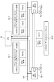
- the existing OpenFlow network includes a controller (OFC) 10, a switch (OFS) 20-1, and a switch (OFS) 20-2.
- the controller (OFC) 10 is connected to the switch (OFS) 20-1 and the switch (OFS) 20-2 via the secure channel network 100.
- a control signal between the controller (OFC) and the switch (OFS) flows through the secure channel network 100.
- One of the control signals is an open flow message.
- the controller (OFC) 10 stores a topology discovery packet (TDP) 30-2 in a packet output message (POM: Packet-Out Message) 30-1, and sends a packet output message (POM) 30 via the secure channel network 100. -1 is transmitted to the switch (OFS) 20-1.
- the packet output message (POM) 30-1 is one of the open flow messages.
- the switch (OFS) 20-1 includes a connection port 21-1.
- the switch (OFS) 20-2 includes a connection port 21-2.
- the connection port 21-1 and the connection port 21-2 are connection ports between switches (OFS).
- the connection port 21-1 and the connection port 21-2 connect the switch (OFS) 20-1 and the switch (OFS) 20-2.
- the switch (OFS) 20-1 acquires the topology discovery packet (TDP) 30-2 stored in the packet output message (POM) 30-1, and sends the topology discovery packet (TDP) 30-2 to the connection port 21-1. Transmit to.
- the topology discovery packet (TDP) 30-2 reaches the connection port 21-2 of the switch (OFS) 20-2 from the connection port 21-1 of the switch (OFS) 20-1.
- the switch (OFS) 20-2 stores the received topology discovery packet (TDP) 30-2 in a packet input message (PIM: Packet-In Message) 30-3, and transmits the packet input message via the secure channel network 100.
- PIM Packet-In Message
- PIM 30-3 is transmitted to the controller (OFC) 10.
- the packet input message (PIM) 30-3 is one of OpenFlow messages.
- the controller (OFC) 10 sets a flow entry for topology discovery packet (TDP) in each switch (OFS).
- TDP topology discovery packet
- the controller (OFC) 10 designates a matching value (MV: Match Value) to which the topology discovery packet (TDP) 30-2 matches in the matching area (MF: Match Field) of this flow entry. That is, the matching value (MV) of the matching area (MF) becomes the rule of the flow entry.
- MV Match Value
- the controller (OFC) 10 sends, as an action (Action) to the action area (AF: Action Field) of this flow entry, “to the controller (OFC) 10 a packet input message (PIM) regarding the topology discovery packet (TDP). "Send”. That is, the action in the action area (AF) becomes the action of the flow entry.
- each switch relates to the topology discovery packet (TDP) 30-2 to the controller (OFC) 10 when the received topology discovery packet (TDP) 30-2 matches the above flow entry.
- a packet input message (PIM) 30-3 is transmitted.
- each switch stores the topology discovery packet (TDP) 30-2 in the data area (DF: Data Field) of the packet input message (PIM) 30-3.
- TDP topology discovery packet
- DF Data Field
- Each switch (OFS) stores “DPID” and “Port” of the switch (OFS) in the packet input message (PIM) 30-3.
- DPID Delivery Point Identifier
- DPID of the switch (OFS) 20-1 is assumed to be “OFS1-DPID”. Further, “DPID” of the switch (OFS) 20-2 is set to “OFS2-DPID”.
- Port is identification information of a connection port of the switch (OFS).
- “Port” of the connection port 21-1 of the switch (OFS) 20-1 is assumed to be “Port1”. Further, “Port” of the connection port 21-2 of the switch (OFS) 20-2 is set to “Port 2”.
- the controller (OFC) 10 sends a packet output message regarding the topology discovery packet (TDP) 30-2 as an open flow message to the link-up port of each switch (OFS) via the secure channel network.
- POM topology discovery packet
- the controller (OFC) 10 sends, as an action, “sends a topology discovery packet (TDP) from the linked up port” to the action area (AF) of the packet output message (POM) 30-1 to be sent. specify.
- TDP topology discovery packet
- AF action area
- POM packet output message
- the controller (OFC) 10 is a transmission destination of the packet output message (POM) 30-1 to the topology discovery packet (TDP) 30-2, and is a transmission source of the topology discovery packet (TDP) 30-2. Designate “DPID” and “Port” of the switch (OFS).
- the switch (OFS) that is the transmission destination of the packet output message (POM) 30-1 and the transmission source of the topology discovery packet (TDP) 30-2 is the switch (OFS) 20-1. .
- the controller (OFC) 10 transmits a packet output message (POM) 30-1 regarding the topology discovery packet (TDP) 30-2 to the switch (OFS) 20-1.
- POM packet output message
- the controller (OFC) 10 stores the topology discovery packet (TDP) 30-2 in the data area (DF) of the packet output message (POM) 30-1.
- controller (OFC) 10 sends, as an action, the topology discovery packet (TDP) from the connection port 21-1 of the switch (OFS) 20-1 to the action area (AF) of the packet output message (POM) 30-1. ) Send 30-2 ".
- the controller (OFC) 10 stores “OFS1-DPID” and “Port1” as “DPID” and “Port” of the switch (OFS) 20-1 in the topology discovery packet (TDP) 30-2.
- “OFS1-DPID” is identification information of the switch (OFS) 20-1.
- the switch (OFS) 20-1 is a switch (OFS) that is a transmission source of the topology discovery packet (TDP) 30-2.
- “Port 1” is identification information of the connection port 21-1.
- the connection port 21-1 is a transmission port for the topology discovery packet (TDP) 30-2.
- the switch (OFS) 20-1 receives the packet output message (POM) 30-1 from the controller (OFC) 10.
- POM packet output message
- the switch (OFS) 20-1 acquires the topology discovery packet (TDP) 30-2 stored in the data area (DF) of the packet output message (POM) 30-1.
- the switch (OFS) 20-1 sends the topology discovery packet (TDP) 30-2 from the connection port 21-1 based on the action designated in the action area (AF) of the packet output message (POM) 30-1. Send.
- connection port 21-1 of the switch (OFS) 20-1 is connected to the connection port 21-2 of the switch (OFS) 20-2. Accordingly, the topology discovery packet (TDP) 30-2 transmitted from the connection port 21-1 of the switch (OFS) 20-1 reaches the connection port 21-2 of the switch (OFS) 20-2.
- TDP topology discovery packet
- the switch (OFS) 20-2 receives the topology discovery packet (TDP) 30-2 at the connection port 21-2.
- TDP topology discovery packet
- OFS controller
- PIM packet input message
- the switch (OFS) 20-2 adds “OFS2-DPID” and “Port2” to the packet input message (PIM) 30-3 as “DPID” and “Port” of the switch (OFS) 20-2. Is stored.
- “OFS2-DPID” is identification information of the switch (OFS) 20-2.
- the switch (OFS) 20-2 is a switch (OFS) that is a transmission source of the packet input message (PIM) 30-3.
- “Port2” is identification information of the connection port 21-2.
- the connection port 21-2 is a reception port for the topology discovery packet (TDP) 30-2.
- the switch (OFS) 20-2 stores the topology discovery packet (TDP) 30-2 in the data area (DF) of the packet input message (PIM) 30-3.
- the controller (OFC) 10 receives the packet input message (PIM) 30-3.
- the controller (OFC) 10 acquires “OFS2-DPID” and “Port2” of the transmission source switch (OFS) 20-2 stored in the packet input message (PIM) 30-3.
- controller (OFC) 10 acquires the topology discovery packet (TDP) 30-2 stored in the data area (DF) of the packet input message (PIM) 30-3, and the topology discovery packet (TDP) 30- “OFS1-DPID” and “Port1” of the switch (OFS) 20-1 stored in 2 are acquired.
- the controller (OFC) 10 detects that the connection port 21-1 of the switch (OFS) 20-1 is connected to the connection port 21-2 of the switch (OFS) 20-2.
- controller (OFC) 10 has the same mechanism as described above, and flows the topology discovery packet (TDP) 30-2 in the reverse direction, so that the connection port 21-2 of the switch (OFS) 20-2 becomes the switch (OFS) 20 -1 connection port 21-1 is detected.
- TDP topology discovery packet
- controller (OFC) 10 maintains and updates the detected topology using the topology discovery packet (TDP) 30-2 and the mechanism described above at a constant interval / retry count during operation. .
- Non-Patent Document 1 OpenFlow Specification Version 1.1.0.
- the topology detection / maintenance procedure in the existing OpenFlow network is useful for initial topology detection in the OpenFlow network.
- the controller In order to maintain and update the detected topology, the controller (OFC) needs to periodically send a topology discovery packet (TDP) to the secure channel network to all links up ports of each switch (OFS).
- TDP topology discovery packet
- the topology discovery packet (TDP) received by each switch (OFS) needs to flow to the controller (OFC) via the secure channel network.
- TDP topology discovery packets
- the timing for detecting the topology change depends on the interval time during which the controller (OFC) issues the topology discovery packet (TDP) during operation and the reply timeout of the topology discovery packet (TDP) from the switch (OFS).
- the switch in the processing of an open flow message, does not use a conventional processing part other than “a part that searches for a flow entry that matches a packet and processes the packet according to an action specified in the matched flow entry”.
- This is realized by software using a general-purpose processor of the legacy switch.
- a routing bridge system is disclosed in Patent Document 1 (Japanese Patent Laid-Open No. 2003-143169).
- a data transmission path is determined using a data link layer address of a network in which a plurality of ring networks in which a plurality of nodes are connected in a ring shape are connected via connection nodes.
- Each node includes a node tree creation unit that creates an inter-node spanning tree between nodes on the ring to which the node belongs.
- Each connected node creates a node tree creation unit that creates an inter-node spanning tree between each node on each ring to which it belongs, and creates an inter-ring spanning tree between each ring with each ring as a logical link
- An inter-ring tree creation unit is provided.
- Patent Document 2 Japanese Patent Laid-Open No. 2006-340361 discloses a method for determining a connection topology of a home network.
- This home network connection topology determination method is a method for determining the connection topology of a home network constituted by a plurality of nodes arranged around multiple hubs and switches.
- topology determination messages are transmitted one by one in a random sequence by the plurality of nodes, all connection topologies of the node are determined one by one based on reception of the topology determination message, and all local Generating and updating a list of nodes.
- the topology determination message includes two consecutive packets.
- the first packet is a broadcast packet with a predetermined payload that identifies it as a topology determination packet.
- the second packet is a unicast packet with the same content and non-existent destination MAC address.
- Patent Document 3 Japanese Patent Laid-Open No. 2008-172449 discloses a topology detection method for detecting a logical topology of a network.
- the communication device records transfer information in which a port number is associated with a source MAC (Media Access Control) address.
- TTL Time To Live
- the management device increments TTL (Time To Live) by 1 sequentially from 1, it sends a trace request including the TTL to the communication device.
- the management device acquires transfer information from the received trace response, and derives a port topology in the network device topology.
- Patent Document 4 Japanese Unexamined Patent Application Publication No. 2009-1119766 discloses the configuration and optimization of a wireless mesh network.
- the network design tool provides an interactive graphical interface for adding, removing, and positioning nodes and equipment in a wireless network, and thresholds, network topology selection, routing settings, and in a wireless mesh network. And a menu including a plurality of interactive screens for specifying communication path and other configuration parameters related to schedule generation and optimization.
- the network design tool automatically applies a set of optimization rules together with parameters input by the user to the network model to generate efficient network configuration data.
- An object of the present invention is to provide a network system that maintains and updates the physical topology of a switch in a situation where the network between the switches has a high delay in an open flow network or the like.
- the network system includes a plurality of switches that process received packets in accordance with a flow entry in which rules and actions for uniformly controlling packets as flows are defined, and a plurality of switches. And a controller for setting the flow entry.
- the controller sets, for each of the plurality of switches, a cyclic flow entry to be deleted when a cyclic packet transmitted / received between the plurality of switches does not arrive.
- a notification to the effect of deletion is received, a failure between a plurality of switches is detected.
- the controller according to the present invention has a mechanism for setting a flow entry in which rules and actions for uniformly controlling a packet as a flow are set for each of the plurality of switches, and for each of the plurality of switches. Received a notification from each switch indicating that the cyclic flow entry was deleted, and a mechanism for setting a cyclic flow entry to be deleted when a cyclic packet transmitted / received between multiple switches no longer arrives. A mechanism for detecting a failure between the plurality of switches.
- the topology management method is a topology management method implemented by a computer.
- rules and actions for uniformly controlling a packet as a flow are defined for each of a plurality of switches. Setting a flow entry for each of a plurality of switches, setting a cyclic flow entry to be deleted when a cyclic packet transmitted and received between the plurality of switches no longer arrives, And detecting a failure between a plurality of switches when a notification that the cyclic flow entry is deleted is received from each switch.
- the program according to the present invention is a program for causing a computer used as a controller to execute the processing in the above topology management method.
- the program according to the present invention can be stored in a storage device or a storage medium.
- the present invention is directed to a CD separation type network.
- an OpenFlow network which is one of CD separation type networks, will be described as an example. However, actually, it is not limited to the OpenFlow network.
- topology keep alive flow entry TKAFE: Topology KeepAlive Flow Entry
- TKAP Topology KeepAlive Packet
- the topology keep alive packet (TKAP) is a cyclic packet defined in advance to maintain and update the detected topology, and is a packet that matches the topology keep alive flow entry (TKAFE).
- TKAFE Topology keep alive flow entry
- TKAP Topicology keep alive packet
- the controller (OFC) 10 is connected to each switch (OFS) 20 via the secure channel network 100.
- a control signal between the controller (OFC) and the switch (OFS) flows through the secure channel network 100.
- each switch (OFS) 20 When each switch (OFS) 20 receives a packet, it compares the flow entry set from the controller (OFC) 10 with the received packet, and the value of the header area (HF: Header Field) of the received packet is the value of the flow entry. When it matches the matching value (MV) of the matching area (MF), the action specified in the action area (AF) of this flow entry is executed.
- HF Header Field
- the controller (OFC) 10 includes a topology management unit 11, a topology detection unit 12, a packet packing / sorting processing unit 13, a packet transmission unit 14, and a packet reception unit 15.
- the topology management unit 11 manages a topology information storage database, and stores topology information of the OpenFlow network detected by the controller (OFC) 10 in the topology information storage database.
- the topology management unit 11 updates the topology information stored in the topology information storage database according to the content of the instruction.
- the topology detection unit 12 has an existing topology detection function, and detects, maintains, and updates the topology. That is, the topology detection unit 12 can create a topology discovery packet (TDP) and detect, maintain, and update the topology as usual. Further, the topology detection unit 12 creates a topology keep alive flow entry (TKAFE) and a topology keep alive packet (TKAP) defined in the present embodiment in order to maintain and update the detected topology.
- TKAFE topology keep alive flow entry
- TKAP topology keep alive packet
- the topology detection unit 12 passes the created information to the packet packing / sorting processing unit 13. Further, the topology detection unit 12 analyzes the topology change notification message received from the packet packing / sorting processing unit 13 and instructs the topology management unit 11 to update the topology information stored in the topology information storage database.
- the packet packing / distribution processing unit 13 packs an actual packet with the information received from the topology detection unit 12 and passes it to the packet transmission unit 14.
- the packet packing / sorting processing unit 13 creates a flow entry change message (MFEM: Modify Flow Entry Message) for adding (registering) a topology keep-alive flow entry (TKAFE) to each switch (OFS) 20.
- MFEM flow entry change message
- This flow entry change message (MFEM) is passed to the packet transmitter 14.
- the packet packing / distribution processing unit 13 stores the topology keep alive packet (TKAP) received from the topology detection unit 12 in the packet output message (POM), and passes this packet output message (POM) to the packet transmission unit 14. .
- TKAP topology keep alive packet
- POM packet output message
- the packet packing / sorting processing unit 13 analyzes the packet received from the packet receiving unit 15 and sorts the packet into an appropriate module. For example, the packet packing / sorting processing unit 13 analyzes the packet input message (PIM) received from the packet receiving unit 15 to acquire / create a topology change notification message, and passes this topology change notification message to the topology detection unit 12. .
- PIM packet input message
- the packet transmission unit 14 transmits the packet received from the packet packing / sorting processing unit 13 to each switch (OFS) 20 via the secure channel network 100. For example, the packet transmission unit 14 transmits a packet output message (POM) to each switch (OFS) 20.
- POM packet output message
- the packet receiving unit 15 receives a packet from each switch (OFS) 20 via the secure channel network 100 and passes the received packet to the packet packing / sorting processing unit 13. For example, the packet receiving unit 15 receives a packet input message (PIM) from each switch (OFS) 20 and passes this packet input message (PIM) to the packet packing / sorting processing unit 13.
- PIM packet input message
- TKAP topology keep alive packet
- BC Broadcast
- MC Multicast
- Non-Patent Document 1 OpenFlow Switch Specification Version 1.1.0
- MF Flow entry matching area
- a simple MAC header frame (Ether Header Frame) is used to reduce packet overhead.
- description of areas other than the MAC header (ether header) area is omitted.
- the topology detection unit 12 sets the following values in each of the MAC transmission source (Ether src) area, the MAC transmission destination (Ether dst) area, and the frame type (Ether Type) area of the MAC header (Ether Header) area. specify.
- the topology detection unit 12 designates a wild card “*” in the MAC transmission source (Ether src) area.
- the topology detection unit 12 designates “MAC address other than broadcast (BC) / multicast (MC)” (Not BC / MC) in the MAC transmission destination (Ether dst) area.
- the topology detection unit 12 designates “0x1111” of “Experimental Type” defined in IANA (Internet Assigned Number Authority) in the frame type (ether type) area.
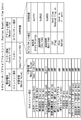
- the packet output message has a header area (HF), an action area (AF), and a data area (DF).
- the header area (HF) is an area for storing information indicating that this message is a packet output message (POM).
- POM packet output message
- the action area (AF) is an area for designating a transmission port for sending a packet stored in the data area (DF).
- the data area (DF) is an area for storing a topology keep alive packet (TKAP).
- the controller (OFC) 10 designates “Type is Packet Out” in the header area (HF) of the packet output message (POM). “Type is Packet Out” is information indicating that this message is a packet output message (POM).
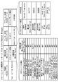
- TKAFE topology keep alive flow entry
- the topology keep alive flow entry has a matching area (MF), a cookie area (CF: Cookie Field), and an action area (AF).
- Matching area is an area indicating entry items used for packet matching.
- the entry item is a matching field (MF) subfield.
- the controller (OFC) 10 designates a matching value (MV) for each entry item indicated in the matching area (MF).
- the entry items of the matching area (MF) include the input port (Ingress Port), metadata (Meta data), MAC transmission source (Ether src), MAC transmission destination (Ether dst), frame type (Ether type), Virtual LAN identifier (VLAN id), Virtual LAN priority (VLAN priority), MPLS label (MPLS label), MPLS traffic class (MPLS traffic class), IP source (IP src), IP destination (IP dst), IP Protocol (IP Protocol), IP service type (IP ToS bits), source port (TCP / UDP src Port), and destination port (TCP / UDP dst Por) ), And the like.
- the input port indicates the port that first received this packet.
- Metadata (Meta data) indicates information related to this packet.
- the MAC transmission source (Ether src), MAC transmission destination (Ether dst), and frame type (Ether type) are 16-bit information for identifying the transmission source MAC address, transmission destination MAC address, and upper layer protocol, respectively. Show.
- MPLS Multi-Protocol Label Switching
- MPLS label indicates a fixed-length identification mark used instead of the IP header.
- the MPLS traffic class (MPLS traffic class) indicates information for specifying and identifying different classes or priorities.
- IP source IP src
- IP destination IP dst
- IP protocol IP Protocol
- IP ToS bits IP service type
- Octet 8-bit octet part included in the header of the IP packet.
- the TOS octet is used to specify processing priority for the purpose of controlling communication quality of service (QoS).
- the transmission source port (TCP / UDP src Port) and the transmission destination port (TCP / UDP dst Port) indicate a transmission source port number and a transmission destination port number, respectively.
- the controller (OFC) 10 sets the topology keep-alive flow entry (TKAFE) in each switch (OFS) 20
- the entry items of the matching area (MF) other than the input port (Ingress Port) and the frame type (Ether type) “ANY” is designated as the matching value (MV).
- each switch (OFS) 20 compares the received packet with the topology keep-alive flow entry (TKAFE), and when both values match for the input port (Ingress Port) and the frame type (Ether type), It is determined that the received packet matches the topology keep alive flow entry (TKAFE).
- the controller (OFC) 10 designates a specific port (Specified Port) as the matching value (MV) of the input port (Ingress Port).
- This specific port (Specified Port) indicates a port connected to each other switch (OFS) 20 among the ports of each switch (OFS) 20 detected by the controller (OFC) 10.
- controller (OFC) 10 designates “0x1111” as the matching value (MV) of the frame type (Ether type). “0x1111” indicates the frame type (Ether type) of the topology keep-alive packet (TKAP) in the present embodiment.
- the cookie area is an area indicating a cookie for temporarily storing data such as additional information.
- a cookie value (CV: Cookie Value) is specified for the cookie.
- the controller (OFC) 10 specifies a 64-bit identifier for the cookie value (CV) of the cookie.
- This 64-bit identifier is an identifier for specifying a flow entry internally managed by the controller (OFC) 10 in which the topology keep alive flow entry (TKAFE) is set.
- the controller (OFC) 10 holds a copy (copy) of the flow entry on each switch (OFS) 20 side in order to grasp and manage the flow entry on each switch (OFS) 20 side.
- the action area (AF) is an area indicating property items (properties) relating to the characteristics of the flow entry.
- the property item is a subfield of the action area (AF).
- the controller (OFC) 10 designates a value (characteristic value) indicating a characteristic for each property item indicated in the action area (AF).
- the property items in the action area include a priority (Entry Priority), an idle time (Idle time), a fixed time (Hard time), a flag (Flag), and an action (Action).
- the controller (OFC) 10 designates “0xffff” as the priority (Entry Priority).
- the priority indicates the priority of the flow entry itself.
- “0xffff” indicates the highest priority (highest priority). That is, the topology keep alive flow entry (TKAFE) is the highest priority flow entry.
- each switch (OFS) 20 compares the topology keep alive flow entry (TKAFE) with the highest priority for the received packet, and executes the action of the topology keep alive flow entry (TKAFE) if they match.
- controller (OFC) 10 designates “0x0003” for the idle time and designates “0x0000” for the fixed time (Hard time). In the designation of time, “0x0003” indicates “3 seconds”. Thereby, when each switch (OFS) 20 does not receive the next topology keep-alive packet (TKAP) within 3 seconds after receiving the topology keep-alive packet (TKAP), the topology keep-alive flow entry It is determined that (TKAFE) has expired (expire: expired, expired), and the topology keep-alive flow entry (TKAFE) is deleted (aged out) from the flow table.
- TKAFE topology keep-alive flow entry
- each switch (OFS) 20 deletes the exposed topology keep-alive flow entry (TKAFE), and then sends an open flow message indicating that the exposed topology keep-alive flow entry (TKAFE) is deleted to the controller (OFC). 10 to send.
- each switch (OFS) 20 deletes the exposed topology keep alive flow entry (TKAFE), and then sends a flow entry deleted message (FERM: Flow Entry Removed Message) to the controller (OFC) 10, which will be described later. Send.
- the controller (OFC) 10 designates “Send to in-port” as an action (Action). “Operation to send a matched packet back to the reception port” indicates an operation to send the packet back to the connection port when the packet received at the connection port matches the flow entry.
- each switch (OFS) 20 sends a topology keep alive packet (TKAP) that matches the topology keep alive flow entry (TKAFE) back to the receiving port.
- TKAP topology keep alive packet
- TKAFE topology keep alive flow entry
- the flow entry change message has a header area (HF), a matching area (MF), a cookie area (CF), and an action area (AF).
- the header area (HF) is an area for storing information indicating that this message is a flow entry change message (MFEM).
- the controller (OFC) 10 designates “Type is Modify State” in the header area (HF) of the flow entry change message (MFEM). “Type is Modify State” is information indicating that this message is a flow entry change message (MFEM).
- the matching area (MF), cookie area (CF), and action area (AF) are basically the same as the topology keep alive flow entry (TKAFE) described in FIG.
- the controller (OFC) 10 When adding a new topology keep alive flow entry (TKAFE), the controller (OFC) 10 designates “add flow entry” (Add Flow entry) in the command (Command). In addition, when modifying an existing topology keep alive flow entry (TKAFE), the controller (OFC) 10 designates “change flow entry” (Modify Flow entry) in the command (Command).
- controller (OFC) 10 designates setting values for the items of the matching area (MF), cookie area (CF), and action area (AF).
- Each switch (OFS) 20 has a matching area (MF), a cookie area (CF), and a “flow entry change” (Modify Flow entry) specified in the action area (AF) command (Command).
- MF matching area
- CF cookie area
- AF action area
- TKAFE topology keep alive flow entry
- Each switch (OFS) 20 has a corresponding topology keep alive flow entry (TKAFE), or “add flow entry” (Add Flow entry) is specified in the command (Command) of the action area (AF).
- TKAFE topology keep alive flow entry
- MF matching area
- CF cookie area
- AF action area
- TKAFE flow entry change message
- Each switch (OFS) 20 includes a matching area (MF), a cookie area (CF), and an action area (AF) of the flow entry change message (MFEM) when a corresponding topology keep alive flow entry (TKAFE) exists.
- MF matching area
- CF cookie area
- AF action area
- MFEM flow entry change message
- TKAFE topology keep alive flow entry
- controller (OFC) 10 can set the created / modified topology keep-alive flow entry (TKAFE) on the side of each switch (OFS) 20.
- the header area is an area for storing information indicating that this message is a flow entry deleted message (FERM).
- each switch (OFS) 20 designates “Type is Flow Removed” in the header area (HF) of the flow entry deleted message (FERM). “Type is Flow Removed” is information indicating that this message is a flow entry deleted message (FERM).
- the matching area (MF), cookie area (CF), and action area (AF) are basically the same as the flow entry change message (MFEM) described in FIG.
- Each switch (OFS) 20 designates “Delete flow entry” (Delete Flow entry) in the command (Command).
- Each switch (OFS) 20 is designated as a topology keep-alive flow entry (TKAFFE) to be deleted in each item of the matching area (MF), cookie area (CF), and action area (AF). Specify a value (default).
- TKAFFE topology keep-alive flow entry
- the controller (OFC) 10 When the controller (OFC) 10 receives the flow entry deleted message (FERM), the controller (OFC) 10 confirms at least one of a command (Command) in the header area (HF) or the action area (AF).
- a command Command
- HF header area
- AF action area
- the controller (OFC) 10 indicates that “Type is Flow Removed” is specified in the header area (HF), or “Delete Flow Entry” (Delete Flow entry) in the action area (AF) command (Command). Is specified, the 64-bit identifier stored in the cookie in the cookie area (CF) is referred to, or the items of the matching area (MF), cookie area (CF), and action area (AF) are Refer to and confirm whether or not the corresponding topology keep-alive flow entry (TKAFE) exists.
- TKAFE topology keep-alive flow entry
- the controller (OFC) 10 ignores and discards this flow entry deleted message (FERM) when the corresponding topology keep-alive flow entry (TKAFE) does not exist.
- FEM flow entry deleted message
- the controller (OFC) 10 deletes the topology keep-alive flow entry (TKAFE) when the corresponding topology keep-alive flow entry (TKAFE) exists.
- each switch (OFS) 20 can reflect the deletion of the exposed topology keep-alive flow entry (TKAFE) on the controller (OFC) 10 side.
- an OpenFlow network is configured by one controller (OFC) 10 and four switches (OFS) 20.
- the controller (OFC) 10 is connected to each of the four switches (OFS) 20 via the secure channel network 100.
- a control signal between the controller (OFC) and the switch (OFS) flows through the secure channel network 100.
- the four switches (OFS) 20 are a switch (OFS) 20-1, a switch (OFS) 20-2, a switch (OFS) 20-3, and a switch (OFS) 20-4, respectively.
- “DPID” of the switch (OFS) 20-1 is assumed to be “OFS1-DPID”.
- the “DPID” of the switch (OFS) 20-2 is set to “OFS2-DPID”.
- the “DPID” of the switch (OFS) 20-3 is set to “OFS3-DPID”.
- the “DPID” of the switch (OFS) 20-4 is set to “OFS4-DPID”.
- “Port 1” that is one of the connection ports of the switch (OFS) 20-1 is connected to “Port 2” that is one of the connection ports of the switch (OFS) 20-2.
- “Port 3” which is one of the connection ports of the switch (OFS) 20-2 is connected to “Port 4” which is one of the connection ports of the switch (OFS) 20-3.
- “Port 5” which is one of the connection ports of the switch (OFS) 20-3 is connected to “Port 6” which is one of the connection ports of the switch (OFS) 20-4.
- “Port7”, which is one of the connection ports of the switch (OFS) 20-4, is connected to “Port8”, which is one of the connection ports of the switch (OFS) 20-1.
- the topology detection unit 12 of the controller (OFC) 10 uses the existing topology detection function to collect the interconnection relationship of the connected switches (OFS) 20 and detects the topology of the OpenFlow network.
- the topology detection unit 12 stores the detected topology information in the topology information storage database of the topology management unit 11 as follows.
- the topology detection unit 12 sequentially takes out the combination of each switch (OFS) and port (Port) stored in the topology information database of the topology management unit 11, and the switch (OFS) and port (Port) ) To create a topology keep-alive flow entry (TKAFE).
- the topology detection unit 12 generates a cookie for identifying the created topology keep alive flow entry (TKAFE) simultaneously with the creation of the topology keep alive flow entry (TKAFE).
- the topology detection unit 12 first generates a topology keep alive flow entry (TKAFE) based on “Port 1” of “OFS1-DPID”.
- TKAFE topology keep alive flow entry
- the topology detection unit 12 designates the following values for each entry item in the matching area (MF) of the generated topology keep alive flow entry (TKAFE).
- the topology detection unit 12 designates “Port 1” as the matching value (MV) of the input port (Ingress Port).
- the topology detection unit 12 designates “0x1111” as the matching value (MV) of the frame type (Ether type).
- the topology detection unit 12 designates “0xffff” as the priority (Entry Priority).
- the topology detection unit 12 designates “0x0003” as the idle time.
- the topology detection unit 12 designates “0x0000” as the fixed time (Hard time).
- the topology detection unit 12 generates a cookie simultaneously with the above specification, and specifies a 64-bit identifier for specifying the flow entry in the cookie value (CV) of the cookie.
- “0x0000000000000001” generated to identify the topology keep alive flow entry (TKAFE) of “Port1” of “OFS1-DPID” is specified as the cookie value (CV) of the cookie.
- the topology detection unit 12 generates a cookie, and then packs information such as the generated topology keep alive flow entry (TKAFFE), cookie value (CV), and “DPID” of the destination switch (OFS) 20-1 into packet packaging / An instruction is sent to the distribution processing unit 13 and packing is performed in a flow entry change message (MFEM) for adding a new flow entry.
- TKAFFE topology keep alive flow entry
- CV cookie value
- DPID DPID of the destination switch
- the packet packing / sorting processing unit 13 creates the flow entry change message (MFEM) described with reference to FIG. 6 based on the information and instructions received from the topology detection unit 12. Further, the packet packing / distribution processing unit 13 passes the created flow entry change message (MFEM), the IP address of the transmission destination switch (OFS), and the port number of the secure channel port to the packet transmission unit 14.
- MFEM flow entry change message
- OFS IP address of the transmission destination switch
- port number of the secure channel port to the packet transmission unit 14.
- the packet transmission unit 14 transmits a flow entry change message (MFEM) from the secure channel port to the transmission destination switch (OFS) based on the information received from the packet packing / sorting processing unit 13.
- MFEM flow entry change message
- the packet transmission unit 14 transmits a flow entry change message (MFEM) to the switch (OFS) 20-1.
- MFEM flow entry change message
- the topology detection unit 12 is a synchronization mechanism of “Barrier Request / Reply” defined by Non-Patent Document 1 (OpenFlow Switch Specification Version 1.1.0), and topology keep-alive flow entry for the switch (OFS) 20-1. Knowing that the addition of (TKAFE) was successful, add the cookie value (CV) of the topology keep alive flow entry (TKAFE) that was successfully added to the topology information database.
- the topology detection unit 12 adds a cookie value (CV) to the topology information database of the topology management unit 11 as follows.
- CV cookie value
- the topology detection unit 12 performs the topology keep for the “Port 2” of “OFS2-DPID” interconnected with “Port 1” of “OFS1-DPID” in the same procedure as described above.
- An alive flow entry (TKAFE) is added, and a cookie value (CV) is set in the topology information database.
- the topology detection unit 12 adds the following cookie value (CV) to the topology information database of the topology management unit 11.
- CV cookie value
- the topology detection unit 12 succeeds in adding a topology keep alive flow entry (TKAFE) to both interconnected switches (OFS), and then the topology keep alive packet (TKAP) and that described in FIG.
- TKAFE topology keep alive flow entry
- TKAP topology keep alive packet
- An instruction to transmit the packet output message (POM) to both switches (OFS) is passed to the packet packing / sorting processing unit 13.
- the packet packing / sorting processing unit 13 stores the topology keep-alive packet (TKAP) in the data area (DF) of the packet output message (POM) based on the information and instructions received from the topology detection unit 12.
- TKAP topology keep-alive packet
- DF data area
- POM packet output message
- the action area (AF) of the packet output message (POM) the operation for transmitting the data area (DF) packet from the interconnection port between the switches (OFS) is specified.
- the packet packing / distribution processing unit 13 sends a packet output message (POM) in which “operation for transmitting a packet from Port 1” is specified in the action area (AF) to the switch (OFS) 20-1. create. Also, a packet output message (POM) in which “operation for transmitting a packet from Port 2” is specified in the action area (AF) is created for the switch (OFS) 20-2.
- POM packet output message
- the packet packing / distribution processing unit 13 passes the packet output message (POM), the IP address of the transmission destination switch (OFS), and the port number of the secure channel port to the packet transmission unit 14.
- POM packet output message
- OFS IP address of the transmission destination switch
- port number of the secure channel port to the packet transmission unit 14.
- the packet transmission unit 14 transmits these packet output messages (POM) to the corresponding transmission destination switches (OFS) based on the information received from the packet packing / sorting processing unit 13.
- POM packet output messages
- OFS transmission destination switches
- the packet transmission unit 14 transmits a packet output message (POM) in which “operation for transmitting a packet from Port 1” is specified in the action area (AF) to the switch (OFS) 20-1. Further, a packet output message (POM) in which “operation for transmitting a packet from Port 2” is specified in the action area (AF) is transmitted to the switch (OFS) 20-2.
- POM packet output message
- the switch (OFS) 20-1 transmits the topology keep alive packet (TKAP) described in FIG. 3 from “Port 1” in accordance with the received packet output message (POM).
- TKAP topology keep alive packet
- the switch (OFS) 20-2 transmits the topology keep alive packet (TKAP) described in FIG. 3 from “Port 2” in accordance with the received packet output message (POM).
- TKAP topology keep alive packet
- TKAP topology keep alive packet
- TKAFE topology keep alive flow entry
- the controller (OFC) 10 registers the topology keep alive flow entry (TKAFE) and topology keep alive packet (TKAP) for all detected combinations of switches (OFS) and ports (Port). To send.
- TKAFE topology keep alive flow entry
- TKAP topology keep alive packet
- the topology keep alive packet (TKAP) cannot correctly reach the interconnection port between the switches (OFS). That is, the packet that matches the topology keep alive flow entry (TKAFE) does not arrive at the switch (OFS).
- TKAFE time when the packet that matches the topology keep alive flow entry (TKAFE) does not arrive exceeds the time set in the idle time (Idle time) of the topology keep alive flow entry (TKAFE), the switch (OFS) It is determined that the flow entry (TKAFE) has expired, and this topology keep alive flow entry (TKAFE) is deleted.
- the switch deletes the exposed topology keep-alive flow entry (TKAFE), and then transmits the flow entry deleted message (FERM) described in FIG. 7 to the controller (OFC) 10.
- the topology detection unit 12 of the controller (OFC) 10 searches the topology information stored in the topology information database by the cookie value (CV) of the flow entry deleted message (FERM) transmitted from the switch (OFS), and It knows that the topology keep alive flow entry (TKAFE) of which port (Port) of the switch (OFS) has expired, and deletes the corresponding topology information from the database.
- CV cookie value
- FAM flow entry deleted message
- the switch (OFS) 20-1 and the switch (OFS) 20-2 each delete the topology keep alive flow entry (TKAFE), and then send a flow entry deleted message (FERM) to the controller (OFC) 10.
- TKAFE topology keep alive flow entry
- FERM flow entry deleted message
- the controller (OFC) 10 receives a flow entry deleted message (FERM) from each of the switch (OFS) 20-1 and the switch (OFS) 20-2.
- FEM flow entry deleted message
- the controller (OFC) 10 determines that there is no interconnection based on the cookie value (CV) stored in each flow entry deleted message (FERM), and deletes the interconnection information from the topology information database. Update the topology change.
- cookie value (CV) stored in the flow entry deleted message (FERM) received from the switch (OFS) 20-1 is “0x0000000000000001”.
- cookie value (CV) stored in the flow entry deleted message (FERM) received from the switch (OFS) 20-2 is “0x0000000000000002”.
- the controller (OFC) 10 updates the topology change by deleting the following interconnection information from the topology information database.
- a topology check is performed at a fixed number of retries using an LLDP packet without immediately determining that a failure has occurred in the interconnect port.
- the network system relates to a network system that maintains and updates a physical topology of a switch in a situation where a network between a controller (OFC) and a switch (OFS) has a high delay in an OpenFlow network, for example.
- OFC controller
- OFS switch
- the controller sends “the packet to the port where the packet has entered” in the action area (AF) for the interconnection port of each switch (OFS).
- "(Send to in-port)” is set, and a flow entry for circulation specifying the idle time is set in the idle time lapse field (Idle timeout Field).
- the topology keep alive flow entry (TKAFE) is one of the cyclic flow entries.
- the controller uses a packet output message (POM) to send a predefined cyclic packet to the interconnection port of each switch (OFS).
- POM packet output message
- TKAP topology keep alive packet
- the traveling packet matches the traveling flow entry for which “Send to in-port” is specified in the action area (AF), and reciprocates between the interconnection ports of each switch (OFS).
- Each switch deletes (ages out) the cyclic flow entry after the idle time specified in the idle time lapse field (Idle timeout Field) of the cyclic flow entry has elapsed.
- the switch notifies the controller (OFC) of an age-out message indicating that the cyclic flow entry has been deleted (aged out).
- the controller determines that a failure has occurred in the interconnection port between the corresponding switches (OFS) based on the age-out message of the flow entry for circulation notified from the switch (OFS).
- the network system uses a mechanism in which the controller (OFC) frequently sends scan packets in the open flow network in order to maintain the topology detected by the controller (OFC) and detect the topology change. Instead, a mechanism is used in which the switch (OFS) dynamically notifies the controller (OFC) of the topology change. Therefore, it is possible to reduce the load on the switch (OFS) on the secure channel network.
- a mechanism of idle time (Idle time), explorer, and flow entry deleted message (FERM) of topology keep alive flow entry (TKAFE) is used. Therefore, it is possible to adjust so as to quickly detect the topology change without imposing a load on the switch (OFS) on the secure channel network.
- the switch processes the topology keep alive packet (TKAP) with an LSI other than the general-purpose processor. Therefore, it is possible to reduce the possibility of erroneously detecting a physical topology change that has not occurred due to insufficient resources of the general-purpose processor of the switch (OFS).
- TKAP topology keep alive packet
- the controller As an example of the controller (OFC), a computer such as a PC (personal computer), an appliance, a thin client server, a workstation, a mainframe, and a supercomputer is assumed.
- the controller (OFC) is not limited to a terminal or a server, but may be a relay device or a peripheral device.
- the controller (OFC) may be an expansion board mounted on a computer or a virtual machine (VM: Virtual Machine) built on a physical machine.
- VM Virtual Machine
- Examples of the switch include a network switch, a router, a proxy, a gateway, a firewall, a load balancer, and a bandwidth control device (load balancer).
- packet shaper security supervisory control device (SCADA: Supervision Control And Data Acquisition), gatekeeper (gatekeeper), base station (base station), access point (AP: Access Point), satellite union , Computers with multiple communication ports Erareru.
- SCADA Security supervisory control device
- gatekeeper gatekeeper
- base station base station
- AP Access Point
- satellite union Computers with multiple communication ports Erareru.
- VM virtual machine
- Each of the controller (OFC) and the switch (OFS) may be mounted on a moving body such as a vehicle, a ship, or an aircraft.
- each of the controller (OFC) and the switch (OFS) is used for communication between a processor that is driven based on a program and executes predetermined processing, a memory that stores the program and various data, and a network. Realized by the interface.
- processors include a CPU (Central Processing Unit), a network processor (NP: Network Processor), a microprocessor (microprocessor), a microcontroller (microcontroller), or a semiconductor integrated circuit (LSI: Large Scale) having a dedicated function. Integration) or the like.
- CPU Central Processing Unit
- NP Network Processor
- microprocessor microprocessor
- microcontroller microcontroller
- LSI semiconductor integrated circuit
- semiconductor storage devices such as RAM (Random Access Memory), ROM (Read Only Memory), EEPROM (Electrically Erasable and Programmable Read Only Memory), and HDD Memory (SDHidK)
- RAM Random Access Memory
- ROM Read Only Memory
- EEPROM Electrically Erasable and Programmable Read Only Memory
- HDD Memory HDD Memory
- An auxiliary storage device such as State Drive
- a removable disk such as a DVD (Digital Versatile Disk)
- a storage medium such as an SD memory card (Secure Digital memory card), or the like
- a buffer, a register, or the like may be used.
- DAS Direct Attached Storage
- FC-SAN Fibre Channel-Storage Area Network
- NAS Network Attached Storage
- IP-SAN IP-Storage Area
- processor and the memory may be integrated.
- a single chip such as a microcomputer has been developed. Therefore, a case where a one-chip microcomputer mounted on an electronic device or the like includes the above processor and the above memory can be considered.
- Examples of the above interfaces include semiconductor integrated circuits such as boards (motherboards and I / O boards) and chips that support network communication, network adapters such as NIC (Network Interface Card), and communication devices such as expansion cards and antennas.
- NIC Network Interface Card
- a communication port such as a connection port (connector) is conceivable.
- networks include the Internet, LAN (Local Area Network), wireless LAN (Wireless LAN), WAN (Wide Area Network), backbone (Backbone), cable TV (CATV) line, fixed telephone network, mobile phone network, WiMAX (IEEE 802.16a), 3G (3rd Generation), dedicated line (lease line), IrDA (Infrared Data Association), Bluetooth (registered trademark), serial communication line, data bus, and the like are conceivable.
- the internal components of the controller may be a module, a component, a dedicated device, or an activation (calling) program thereof.
Landscapes
- Engineering & Computer Science (AREA)
- Computer Networks & Wireless Communication (AREA)
- Signal Processing (AREA)
- Environmental & Geological Engineering (AREA)
- Health & Medical Sciences (AREA)
- Cardiology (AREA)
- General Health & Medical Sciences (AREA)
- Data Exchanges In Wide-Area Networks (AREA)
Description
ネットワークシステムの制御方式の1つとして、外部の制御装置(コントロールプレーン)からノード装置(データプレーン)を制御するCD(C:コントロールプレーン/D:データプレーン)分離型ネットワークが提案されている。
オープンフローネットワークでは、オープンフローコントローラ(OFC:OpenFlow Controller)が、オープンフロースイッチ(OFS:OpenFlow Switch)のフローテーブルを操作することによりスイッチの挙動を制御する。コントローラとスイッチの間は、コントローラがオープンフロープロトコルに準拠した制御メッセージであるオープンフローメッセージ(OpenFlow Message)を用いてスイッチを制御するためのセキュアチャンネル(Secure Channel)により接続されている。
オープンフローネットワークでは、コントローラ(OFC)は、LLDP(Link Layer Discovery Protocol)やOFDP(OpenFlow Discovery Protocol)等のトポロジーディスカバリープロトコル(Topology Discovery Protocol)を利用し、隣接スイッチ(OsFS)間の接続情報を収集する。なお、OFDPは、LLDPを拡張したオープンフロー用のトポロジー検出プロトコルである。
図1を参照して、既存のオープンフローネットワークにおけるトポロジー検出・維持の手順について説明する。
まず、トポロジー検出処理の開始前に行うべき初期設定処理について説明する。
次に、初期設定処理の完了後に行われるトポロジー検出処理について説明する。
上記の既存のオープンフローネットワークにおけるトポロジー検出・維持の手順は、オープンフローネットワークにおけるトポロジーの初期検出には有用であるが、検出したトポロジーを維持・更新する場合には、以下の(1)~(3)のような問題点がある。
以下に、本発明の第1実施形態について添付図面を参照して説明する。
図2を参照して、本発明に係るネットワークシステムの構成例について説明する。
次に、コントローラ(OFC)10の構成例について説明する。
図3を参照して、本発明に係るトポロジーキープアライブパケット(TKAP)の仕様について説明する。
図4を参照して、本発明に係るパケット出力メッセージ(POM)の仕様について説明する。
図5を参照して、本発明に係るトポロジーキープアライブフローエントリ(TKAFE)の仕様について説明する。
まず、整合領域(MF)について説明する。
次に、クッキー領域(CF)について説明する。
次に、アクション領域(AF)について説明する。
図6を参照して、コントローラ(OFC)10が各スイッチ(OFS)20にトポロジーキープアライブフローエントリ(TKAFE)を追加(登録)するためのフローエントリ変更メッセージ(MFEM)の仕様について説明する。
図7を参照して、各スイッチ(OFS)20がエクスパイヤしたトポロジーキープアライブフローエントリ(TKAFE)を削除した後に、コントローラ(OFC)10に送信するフローエントリ削除済メッセージ(FERM)の仕様について説明する。
図8を参照して、本発明に係るネットワークシステムの実施例について説明する。
まず、トポロジーを初期検出した際の動作について説明する。
次に、トポロジーを維持・更新する際の動作について説明する。
次に、スイッチ(OFS)間の相互接続ポートやネットワークに障害が発生した際の動作について説明する。
以下に、本発明の第2実施形態について説明する。
なお、上記の各実施形態は、組み合わせて実施することも可能である。
次に、本発明の特徴について説明する。
以下に、本発明に係るネットワークシステムを実現するための具体的なハードウェアの例について説明する。
以上、本発明の実施形態を詳述してきたが、実際には、上記の実施形態に限られるものではなく、本発明の要旨を逸脱しない範囲の変更があっても本発明に含まれる。
Claims (12)
- パケットをフローとして一律に制御するためのルールとアクションとが定義されたフローエントリに従って、受信したパケットの処理を行う複数のスイッチと、
前記複数のスイッチの各々に対して、前記複数のスイッチ間で相互に送受信される巡回パケットが到着しなくなった場合に削除される巡回用フローエントリを設定し、前記各スイッチから、前記巡回用フローエントリを削除した旨の通知を受信した場合、前記複数のスイッチ間の障害を検出するコントローラと
を含む
ネットワークシステム。 - 請求項1に記載のネットワークシステムであって、
前記コントローラは、
前記巡回用フローエントリに、パケットが入ってきたポートに当該パケットを転送する旨のアクションと、マッチするパケットが到着しなくなってからの有効期間を示す遊休時間と、を指定して前記各スイッチに設定する手段と、
前記巡回パケットを作成して前記各スイッチに送信する手段と、
前記各スイッチから、前記遊休時間が経過した巡回用フローエントリを削除した旨の通知を受信する手段と
を具備する
ネットワークシステム。 - 請求項2に記載のネットワークシステムであって、
前記コントローラは、
前記遊休時間が経過した巡回用フローエントリを削除した旨の通知を受信した際に、LLDPパケットを利用して一定のリトライ回数でトポロジー検査を行う手段と、
前記LLDPパケットを利用したトポロジー検査でも相互接続関係を確認できない場合、前記複数のスイッチ間に障害が発生したと判断する手段と
を更に具備する
ネットワークシステム。 - 複数のスイッチの各々に対して、パケットをフローとして一律に制御するためのルールとアクションとが定義されたフローエントリを設定する手段と、
前記複数のスイッチの各々に対して、前記複数のスイッチ間で相互に送受信される巡回パケットが到着しなくなった場合に削除される巡回用フローエントリを設定する手段と、
前記各スイッチから、前記巡回用フローエントリを削除した旨の通知を受信した場合、前記複数のスイッチ間の障害を検出する手段と
を具備する
コントローラ。 - 請求項4に記載のコントローラであって、
前記巡回用フローエントリに、パケットが入ってきたポートに当該パケットを転送する旨のアクションと、マッチするパケットが到着しなくなってからの有効期間を示す遊休時間と、を指定して前記各スイッチに設定する手段と、
前記巡回パケットを作成して前記各スイッチに送信する手段と、
前記各スイッチから、前記遊休時間が経過した巡回用フローエントリを削除した旨の通知を受信する手段と
を更に具備する
コントローラ。 - 請求項5に記載のコントローラであって、
前記遊休時間が経過した巡回用フローエントリを削除した旨の通知を受信した際に、LLDPパケットを利用して一定のリトライ回数でトポロジー検査を行う手段と、
前記LLDPパケットを利用したトポロジー検査でも相互接続関係を確認できない場合、前記複数のスイッチ間に障害が発生したと判断する手段と
を更に具備する
コントローラ。 - 計算機により実施されるトポロジー管理方法であって、
コントローラとして、複数のスイッチの各々に対して、パケットをフローとして一律に制御するためのルールとアクションとが定義されたフローエントリを設定することと、
前記複数のスイッチの各々に対して、前記複数のスイッチ間で相互に送受信される巡回パケットが到着しなくなった場合に削除される巡回用フローエントリを設定することと、
前記各スイッチから、前記巡回用フローエントリを削除した旨の通知を受信した場合、前記複数のスイッチ間の障害を検出することと
を含む
トポロジー管理方法。 - 請求項7に記載のトポロジー管理方法であって、
前記巡回用フローエントリに、パケットが入ってきたポートに当該パケットを転送する旨のアクションと、マッチするパケットが到着しなくなってからの有効期間を示す遊休時間と、を指定して前記各スイッチに設定することと、
前記巡回パケットを作成して前記各スイッチに送信することと、
前記各スイッチから、前記遊休時間が経過した巡回用フローエントリを削除した旨の通知を受信することと
を更に含む
トポロジー管理方法。 - 請求項8に記載のトポロジー管理方法であって、
前記遊休時間が経過した巡回用フローエントリを削除した旨の通知を受信した際に、LLDPパケットを利用して一定のリトライ回数でトポロジー検査を行うことと、
前記LLDPパケットを利用したトポロジー検査でも相互接続関係を確認できない場合、前記複数のスイッチ間に障害が発生したと判断することと
を更に含む
トポロジー管理方法。 - コントローラとして、複数のスイッチの各々に対して、パケットをフローとして一律に制御するためのルールとアクションとが定義されたフローエントリを設定するステップと、
前記複数のスイッチの各々に対して、前記複数のスイッチ間で相互に送受信される巡回パケットが到着しなくなった場合に削除される巡回用フローエントリを設定するステップと、
前記各スイッチから、前記巡回用フローエントリを削除した旨の通知を受信した場合、前記複数のスイッチ間の障害を検出するステップと
を計算機に実行させるためのプログラムを格納した記憶媒体。 - 請求項10に記載の記憶媒体であって、
前記巡回用フローエントリに、パケットが入ってきたポートに当該パケットを転送する旨のアクションと、マッチするパケットが到着しなくなってからの有効期間を示す遊休時間と、を指定して前記各スイッチに設定するステップと、
前記巡回パケットを作成して前記各スイッチに送信するステップと、
前記各スイッチから、前記遊休時間が経過した巡回用フローエントリを削除した旨の通知を受信するステップと
を更に計算機に実行させるためのプログラムを格納した
記憶媒体。 - 請求項11に記載の記憶媒体であって、
前記遊休時間が経過した巡回用フローエントリを削除した旨の通知を受信した際に、LLDPパケットを利用して一定のリトライ回数でトポロジー検査を行うステップと、
前記LLDPパケットを利用したトポロジー検査でも相互接続関係を確認できない場合、前記複数のスイッチ間に障害が発生したと判断するステップと
を更に計算機に実行させるためのプログラムを格納した
記憶媒体。
Priority Applications (5)
| Application Number | Priority Date | Filing Date | Title |
|---|---|---|---|
| US14/371,717 US9467363B2 (en) | 2012-01-30 | 2013-01-29 | Network system and method of managing topology |
| CN201380007322.2A CN104081731B (zh) | 2012-01-30 | 2013-01-29 | 网络系统以及管理拓扑的方法 |
| EP13743795.0A EP2811702A4 (en) | 2012-01-30 | 2013-01-29 | NETWORK SYSTEM AND TOPOLOGY MANAGEMENT METHOD |
| JP2013556411A JP5846221B2 (ja) | 2012-01-30 | 2013-01-29 | ネットワークシステム、及びトポロジー管理方法 |
| IN5741DEN2014 IN2014DN05741A (ja) | 2012-01-30 | 2014-07-10 |
Applications Claiming Priority (2)
| Application Number | Priority Date | Filing Date | Title |
|---|---|---|---|
| JP2012016225 | 2012-01-30 | ||
| JP2012-016225 | 2012-01-30 |
Publications (1)
| Publication Number | Publication Date |
|---|---|
| WO2013115177A1 true WO2013115177A1 (ja) | 2013-08-08 |
Family
ID=48905212
Family Applications (1)
| Application Number | Title | Priority Date | Filing Date |
|---|---|---|---|
| PCT/JP2013/051889 Ceased WO2013115177A1 (ja) | 2012-01-30 | 2013-01-29 | ネットワークシステム、及びトポロジー管理方法 |
Country Status (6)
| Country | Link |
|---|---|
| US (1) | US9467363B2 (ja) |
| EP (1) | EP2811702A4 (ja) |
| JP (1) | JP5846221B2 (ja) |
| CN (1) | CN104081731B (ja) |
| IN (1) | IN2014DN05741A (ja) |
| WO (1) | WO2013115177A1 (ja) |
Cited By (3)
| Publication number | Priority date | Publication date | Assignee | Title |
|---|---|---|---|---|
| WO2015114714A1 (ja) * | 2014-02-03 | 2015-08-06 | 日本電気株式会社 | ネットワークトポロジー検出システム、方法およびプログラムならびに制御装置 |
| JP2018133799A (ja) * | 2017-02-14 | 2018-08-23 | 廣達電腦股▲ふん▼有限公司 | リンクディスカバリ情報をセキュアに交換する方法 |
| JP2018528716A (ja) * | 2015-09-25 | 2018-09-27 | 華為技術有限公司Huawei Technologies Co.,Ltd. | 経路検出方法および装置 |
Families Citing this family (33)
| Publication number | Priority date | Publication date | Assignee | Title |
|---|---|---|---|---|
| CN103259728B (zh) * | 2013-05-24 | 2016-03-30 | 华为技术有限公司 | 一种ofs带内通信方法及ofs |
| US9374308B2 (en) * | 2013-08-30 | 2016-06-21 | Lenovo Enterprise Solutions (Singapore) Pte. Ltd. | Openflow switch mode transition processing |
| EP3047607B1 (en) | 2013-09-20 | 2017-09-06 | Telefonaktiebolaget LM Ericsson (publ) | In band control channels of a communication network |
| US9356855B2 (en) * | 2013-10-10 | 2016-05-31 | Ixia | Methods, systems, and computer readable media for providing for specification or autodiscovery of device under test (DUT) topology information |
| US9628356B2 (en) * | 2013-10-10 | 2017-04-18 | Ixia | Methods, systems, and computer readable media for providing user interfaces for specification of system under test (SUT) and network tap topology and for presenting topology specific test results |
| US9743367B2 (en) * | 2014-09-18 | 2017-08-22 | Lenovo Enterprise Solutions (Singapore) Pte. Ltd. | Link layer discovery protocol (LLDP) on multiple nodes of a distributed fabric |
| US10015048B2 (en) | 2014-12-27 | 2018-07-03 | Intel Corporation | Programmable protocol parser for NIC classification and queue assignments |
| CN105871964B (zh) * | 2015-01-23 | 2020-08-07 | 中兴通讯股份有限公司 | 用户设备ue处理方法及装置 |
| EP3257205B1 (en) * | 2015-02-12 | 2019-11-20 | Telefonaktiebolaget LM Ericsson (publ) | Discovering links between operating domains in a communication network |
| JP2016181819A (ja) * | 2015-03-24 | 2016-10-13 | 富士通株式会社 | ネットワークの制御装置及び制御方法、並びに、ネットワークスイッチ |
| EP3073701B1 (en) * | 2015-03-27 | 2017-10-04 | Deutsche Telekom AG | Network protection entity and method for protecting a communication network against fraud messages |
| US9826071B2 (en) | 2015-08-26 | 2017-11-21 | Barefoot Networks, Inc. | Configuring a switch for extracting packet header fields |
| US9825862B2 (en) | 2015-08-26 | 2017-11-21 | Barefoot Networks, Inc. | Packet header field extraction |
| US10868708B2 (en) | 2015-11-02 | 2020-12-15 | Google Llc | System and method for handling link loss in a network |
| US9912774B2 (en) | 2015-12-22 | 2018-03-06 | Intel Corporation | Accelerated network packet processing |
| CN105634817A (zh) * | 2016-01-08 | 2016-06-01 | 广州西麦科技股份有限公司 | 一种基于sdn的网络故障自动检测的系统及方法 |
| US10484282B2 (en) | 2016-01-12 | 2019-11-19 | International Business Machines Corporation | Interconnecting multiple separate openflow domains |
| US10063407B1 (en) | 2016-02-08 | 2018-08-28 | Barefoot Networks, Inc. | Identifying and marking failed egress links in data plane |
| CN107204924B (zh) * | 2016-03-18 | 2020-09-25 | 华为技术有限公司 | 链路发现方法及装置 |
| KR20180041977A (ko) * | 2016-10-17 | 2018-04-25 | 숭실대학교산학협력단 | 링크 검출 서비스에 대한 인증을 지원하는 소프트웨어 정의 네트워크 및 이에 포함되는 컨트롤러 |
| US20180175772A1 (en) * | 2016-12-21 | 2018-06-21 | Rockwell Automation Technologies, Inc. | Motor drive with multi-function high speed communications interface |
| US11296640B2 (en) * | 2016-12-21 | 2022-04-05 | Rockwell Automation Technologies, Inc. | Motor drive with dynamic interval communication |
| US11139768B2 (en) * | 2016-12-21 | 2021-10-05 | Rockwell Automation Technologies, Inc. | Motor drive with independent physical backplane communication |
| US10419366B1 (en) * | 2017-01-31 | 2019-09-17 | Barefoot Networks, Inc. | Mechanism for communicating to remote control plane from forwarding element |
| CN106982169B (zh) * | 2017-03-30 | 2020-01-03 | 新华三技术有限公司 | 报文转发方法及装置 |
| US10355939B2 (en) * | 2017-04-13 | 2019-07-16 | International Business Machines Corporation | Scalable data center network topology on distributed switch |
| US10694006B1 (en) | 2017-04-23 | 2020-06-23 | Barefoot Networks, Inc. | Generation of descriptive data for packet fields |
| CN109104339A (zh) | 2017-06-21 | 2018-12-28 | 富士通株式会社 | 信息传输方法、装置及电子设备 |
| US10601732B1 (en) | 2017-07-23 | 2020-03-24 | Barefoot Networks, Inc. | Configurable packet processing pipeline for handling non-packet data |
| US10594630B1 (en) | 2017-09-28 | 2020-03-17 | Barefoot Networks, Inc. | Expansion of packet data within processing pipeline |
| US11563722B2 (en) * | 2019-08-22 | 2023-01-24 | Hewlett Packard Enterprise Development Lp | Firewall coordination in a network |
| US10917326B1 (en) | 2019-08-23 | 2021-02-09 | Keysight Technologies, Inc. | Methods, systems, and computer readable media for debugging test traffic generation |
| CN112887756B (zh) * | 2021-01-11 | 2023-02-07 | 上海七牛信息技术有限公司 | 一种多媒体微服务的多输入多输出通信系统及方法 |
Citations (7)
| Publication number | Priority date | Publication date | Assignee | Title |
|---|---|---|---|---|
| JP2003143169A (ja) | 2001-11-01 | 2003-05-16 | Nec Corp | ルーティングブリッジシステム、ノード、接続ノード、及びルーティングプログラム |
| JP2006340361A (ja) | 2005-06-01 | 2006-12-14 | Thomson Licensing | ホームネットワークのコネクショントポロジーの決定方法 |
| JP2008172449A (ja) | 2007-01-10 | 2008-07-24 | Kddi Corp | ネットワークの論理トポロジを検出するトポロジ検出方法、通信装置、管理装置及びプログラム |
| JP2009111976A (ja) | 2007-08-31 | 2009-05-21 | Fisher Rosemount Syst Inc | 無線メッシュ型ネットワークの構成および最適化 |
| WO2010143607A1 (ja) * | 2009-06-08 | 2010-12-16 | 日本電気株式会社 | 通信ネットワーク管理システム、方法、及び管理計算機 |
| US20110286324A1 (en) * | 2010-05-19 | 2011-11-24 | Elisa Bellagamba | Link Failure Detection and Traffic Redirection in an Openflow Network |
| JP2012016225A (ja) | 2010-07-02 | 2012-01-19 | Omron Corp | 電圧変換回路、および電子機器 |
Family Cites Families (4)
| Publication number | Priority date | Publication date | Assignee | Title |
|---|---|---|---|---|
| US7782793B2 (en) | 2005-09-15 | 2010-08-24 | Alcatel Lucent | Statistical trace-based methods for real-time traffic classification |
| US8717911B2 (en) | 2006-06-30 | 2014-05-06 | Centurylink Intellectual Property Llc | System and method for collecting network performance information |
| US8005012B1 (en) * | 2009-01-30 | 2011-08-23 | Juniper Networks, Inc. | Traffic analysis of data flows |
| JP5408243B2 (ja) * | 2009-03-09 | 2014-02-05 | 日本電気株式会社 | OpenFlow通信システムおよびOpenFlow通信方法 |
-
2013
- 2013-01-29 EP EP13743795.0A patent/EP2811702A4/en not_active Withdrawn
- 2013-01-29 CN CN201380007322.2A patent/CN104081731B/zh not_active Expired - Fee Related
- 2013-01-29 US US14/371,717 patent/US9467363B2/en active Active
- 2013-01-29 WO PCT/JP2013/051889 patent/WO2013115177A1/ja not_active Ceased
- 2013-01-29 JP JP2013556411A patent/JP5846221B2/ja not_active Expired - Fee Related
-
2014
- 2014-07-10 IN IN5741DEN2014 patent/IN2014DN05741A/en unknown
Patent Citations (7)
| Publication number | Priority date | Publication date | Assignee | Title |
|---|---|---|---|---|
| JP2003143169A (ja) | 2001-11-01 | 2003-05-16 | Nec Corp | ルーティングブリッジシステム、ノード、接続ノード、及びルーティングプログラム |
| JP2006340361A (ja) | 2005-06-01 | 2006-12-14 | Thomson Licensing | ホームネットワークのコネクショントポロジーの決定方法 |
| JP2008172449A (ja) | 2007-01-10 | 2008-07-24 | Kddi Corp | ネットワークの論理トポロジを検出するトポロジ検出方法、通信装置、管理装置及びプログラム |
| JP2009111976A (ja) | 2007-08-31 | 2009-05-21 | Fisher Rosemount Syst Inc | 無線メッシュ型ネットワークの構成および最適化 |
| WO2010143607A1 (ja) * | 2009-06-08 | 2010-12-16 | 日本電気株式会社 | 通信ネットワーク管理システム、方法、及び管理計算機 |
| US20110286324A1 (en) * | 2010-05-19 | 2011-11-24 | Elisa Bellagamba | Link Failure Detection and Traffic Redirection in an Openflow Network |
| JP2012016225A (ja) | 2010-07-02 | 2012-01-19 | Omron Corp | 電圧変換回路、および電子機器 |
Non-Patent Citations (3)
| Title |
|---|
| HISATOSHI OIKAWA ET AL.: "Open Flow Network ni Okeru Keiro Joho no Tsuchi Shuho ni Kansuru Teian", DAI 73 KAI (HEISEI 23 NEN) ZENKOKU TAIKAI KOEN RONBUNSHU (3), INFORMATION PROCESSING SOCIETY OF JAPAN, 2 March 2011 (2011-03-02), pages 3-319 - 3-320, XP008174996 * |
| OPENFLOW SWITCH SPECIFICATION, VERSION 1.1.0 IMPLEMENTED, 28 February 2011 (2011-02-28), Retrieved from the Internet <URL:http://www. openflowswitch.org/documents/openflow-spec-vl.l.Opdf> |
| See also references of EP2811702A4 |
Cited By (4)
| Publication number | Priority date | Publication date | Assignee | Title |
|---|---|---|---|---|
| WO2015114714A1 (ja) * | 2014-02-03 | 2015-08-06 | 日本電気株式会社 | ネットワークトポロジー検出システム、方法およびプログラムならびに制御装置 |
| JP2018528716A (ja) * | 2015-09-25 | 2018-09-27 | 華為技術有限公司Huawei Technologies Co.,Ltd. | 経路検出方法および装置 |
| US10659253B2 (en) | 2015-09-25 | 2020-05-19 | Huawei Technologies Co., Ltd. | Path detection method and apparatus |
| JP2018133799A (ja) * | 2017-02-14 | 2018-08-23 | 廣達電腦股▲ふん▼有限公司 | リンクディスカバリ情報をセキュアに交換する方法 |
Also Published As
| Publication number | Publication date |
|---|---|
| US9467363B2 (en) | 2016-10-11 |
| US20150003259A1 (en) | 2015-01-01 |
| EP2811702A1 (en) | 2014-12-10 |
| CN104081731B (zh) | 2017-06-23 |
| JP5846221B2 (ja) | 2016-01-20 |
| JPWO2013115177A1 (ja) | 2015-05-11 |
| IN2014DN05741A (ja) | 2015-04-10 |
| CN104081731A (zh) | 2014-10-01 |
| EP2811702A4 (en) | 2015-08-26 |
Similar Documents
| Publication | Publication Date | Title |
|---|---|---|
| JP5846221B2 (ja) | ネットワークシステム、及びトポロジー管理方法 | |
| US9515868B2 (en) | System and method for communication | |
| EP3332511B1 (en) | Method and system for path monitoring in a software-defined networking (sdn) system | |
| JP5610247B2 (ja) | ネットワークシステム、及びポリシー経路設定方法 | |
| US9215175B2 (en) | Computer system including controller and plurality of switches and communication method in computer system | |
| RU2583745C2 (ru) | Сетевая система, коммутатор и способ обнаружения подсоединенного терминала | |
| JP5557066B2 (ja) | スイッチシステム、モニタリング集中管理方法 | |
| KR101562726B1 (ko) | 통신 경로 제어 시스템, 및 통신 경로 제어 방법 | |
| EP2731313B1 (en) | Distributed cluster processing system and message processing method thereof | |
| CN103262472B (zh) | 计算机系统、控制器、控制器管理器和通信路由分析方法 | |
| WO2016193852A1 (en) | Method and system for resynchronization of forwarding states in a network forwarding device | |
| JP4532253B2 (ja) | フレーム転送装置及びフレームのループ抑止方法 | |
| Lopez-Pajares et al. | Amaru: Plug&play resilient in-band control for SDN | |
| EP2916497A1 (en) | Communication system, path information exchange device, communication node, transfer method for path information and program | |
| EP3817341B1 (en) | Bulk configuration of devices behind a network address translation device | |
| JP5966488B2 (ja) | ネットワークシステム、スイッチ、及び通信遅延短縮方法 | |
| WO2014175423A1 (ja) | 通信ノード、通信システム、パケット処理方法及びプログラム | |
| WO2021224931A1 (en) | System and a method to efficiently exchange echo and stats messages between sdn controller and the open vswitches | |
| Manzanares-Lopez et al. | Host Discovery Solution: An Enhancement of Topology Discovery in OpenFlow based SDN Networks. | |
| JP2013115733A (ja) | ネットワークシステム、及びネットワーク制御方法 |
Legal Events
| Date | Code | Title | Description |
|---|---|---|---|
| 121 | Ep: the epo has been informed by wipo that ep was designated in this application |
Ref document number: 13743795 Country of ref document: EP Kind code of ref document: A1 |
|
| ENP | Entry into the national phase |
Ref document number: 2013556411 Country of ref document: JP Kind code of ref document: A |
|
| WWE | Wipo information: entry into national phase |
Ref document number: 2013743795 Country of ref document: EP |
|
| WWE | Wipo information: entry into national phase |
Ref document number: 14371717 Country of ref document: US |
|
| NENP | Non-entry into the national phase |
Ref country code: DE |