WO2013115224A1 - 界磁極用磁石体を構成する磁石片の製造方法 - Google Patents
界磁極用磁石体を構成する磁石片の製造方法 Download PDFInfo
- Publication number
- WO2013115224A1 WO2013115224A1 PCT/JP2013/051999 JP2013051999W WO2013115224A1 WO 2013115224 A1 WO2013115224 A1 WO 2013115224A1 JP 2013051999 W JP2013051999 W JP 2013051999W WO 2013115224 A1 WO2013115224 A1 WO 2013115224A1
- Authority
- WO
- WIPO (PCT)
- Prior art keywords
- magnet
- magnet body
- groove
- cleaving
- manufacturing
- Prior art date
- Legal status (The legal status is an assumption and is not a legal conclusion. Google has not performed a legal analysis and makes no representation as to the accuracy of the status listed.)
- Ceased
Links
Images


Classifications
-
- H—ELECTRICITY
- H01—ELECTRIC ELEMENTS
- H01F—MAGNETS; INDUCTANCES; TRANSFORMERS; SELECTION OF MATERIALS FOR THEIR MAGNETIC PROPERTIES
- H01F41/00—Apparatus or processes specially adapted for manufacturing or assembling magnets, inductances or transformers; Apparatus or processes specially adapted for manufacturing materials characterised by their magnetic properties
- H01F41/02—Apparatus or processes specially adapted for manufacturing or assembling magnets, inductances or transformers; Apparatus or processes specially adapted for manufacturing materials characterised by their magnetic properties for manufacturing cores, coils, or magnets
- H01F41/0253—Apparatus or processes specially adapted for manufacturing or assembling magnets, inductances or transformers; Apparatus or processes specially adapted for manufacturing materials characterised by their magnetic properties for manufacturing cores, coils, or magnets for manufacturing permanent magnets
-
- B—PERFORMING OPERATIONS; TRANSPORTING
- B26—HAND CUTTING TOOLS; CUTTING; SEVERING
- B26F—PERFORATING; PUNCHING; CUTTING-OUT; STAMPING-OUT; SEVERING BY MEANS OTHER THAN CUTTING
- B26F3/00—Severing by means other than cutting; Apparatus therefor
- B26F3/002—Precutting and tensioning or breaking
-
- H—ELECTRICITY
- H02—GENERATION; CONVERSION OR DISTRIBUTION OF ELECTRIC POWER
- H02K—DYNAMO-ELECTRIC MACHINES
- H02K1/00—Details of the magnetic circuit
- H02K1/06—Details of the magnetic circuit characterised by the shape, form or construction
- H02K1/22—Rotating parts of the magnetic circuit
- H02K1/27—Rotor cores with permanent magnets
- H02K1/2706—Inner rotors
- H02K1/272—Inner rotors the magnetisation axis of the magnets being perpendicular to the rotor axis
- H02K1/274—Inner rotors the magnetisation axis of the magnets being perpendicular to the rotor axis the rotor consisting of two or more circumferentially positioned magnets
- H02K1/2753—Inner rotors the magnetisation axis of the magnets being perpendicular to the rotor axis the rotor consisting of two or more circumferentially positioned magnets the rotor consisting of magnets or groups of magnets arranged with alternating polarity
- H02K1/276—Magnets embedded in the magnetic core, e.g. interior permanent magnets [IPM]
-
- H—ELECTRICITY
- H02—GENERATION; CONVERSION OR DISTRIBUTION OF ELECTRIC POWER
- H02K—DYNAMO-ELECTRIC MACHINES
- H02K15/00—Processes or apparatus specially adapted for manufacturing, assembling, maintaining or repairing of dynamo-electric machines
- H02K15/02—Processes or apparatus specially adapted for manufacturing, assembling, maintaining or repairing of dynamo-electric machines of stator or rotor bodies
- H02K15/03—Processes or apparatus specially adapted for manufacturing, assembling, maintaining or repairing of dynamo-electric machines of stator or rotor bodies having permanent magnets
-
- Y—GENERAL TAGGING OF NEW TECHNOLOGICAL DEVELOPMENTS; GENERAL TAGGING OF CROSS-SECTIONAL TECHNOLOGIES SPANNING OVER SEVERAL SECTIONS OF THE IPC; TECHNICAL SUBJECTS COVERED BY FORMER USPC CROSS-REFERENCE ART COLLECTIONS [XRACs] AND DIGESTS
- Y10—TECHNICAL SUBJECTS COVERED BY FORMER USPC
- Y10T—TECHNICAL SUBJECTS COVERED BY FORMER US CLASSIFICATION
- Y10T225/00—Severing by tearing or breaking
- Y10T225/10—Methods
- Y10T225/12—With preliminary weakening
Definitions
- the present invention relates to a method for manufacturing a magnet piece constituting a field pole magnet body disposed in a permanent magnet rotating electrical machine.
- JP2009-33958A a plate-shaped magnet body is cleaved into a plurality of magnet pieces, and the plurality of magnet pieces are bonded to each other so as to be accommodated in the rotor core of the permanent magnet embedded rotary electric machine. Techniques for manufacturing the are disclosed.
- the manufactured field pole magnet body the volume of the individual magnet pieces is small, the eddy current generated in the magnet piece becomes smaller by the magnetic field variation of by rotation of the rotor.
- the heat generation of the field pole magnet body accompanying the generation of eddy current can be suppressed, and irreversible thermal demagnetization can be prevented.
- an object of the present invention is to provide a method of manufacturing a magnet piece constituting a field pole magnet body capable of suppressing the occurrence of abnormal cracking.
- a method of manufacturing a magnet piece that constitutes a field pole magnet body in which the magnet body is cleaved at a plurality of cleaved portions arranged at intervals in the longitudinal direction.
- the magnet body in which a deeper groove is formed closer to one end portion in the longitudinal direction of the magnet body the cleaved portion closer to the one end portion.
- a cleaving step of cleaving in order from the part is included.
- FIG. 1A is a schematic configuration diagram of a main part of a permanent magnet type electric motor.
- 1B is a cross-sectional view taken along the line IB-IB in FIG. 1A.
- FIG. 2 is a configuration diagram of a field pole magnet body.
- FIG. 3 is a schematic configuration diagram of an apparatus used for breaking a magnet body to make a magnet piece.
- FIG. 4 is a view for explaining grooves formed in the magnet body.
- FIG. 5 is a diagram for explaining a modification of the groove formed in the magnet body.
- the rotating electrical machine 1 includes an annular stator 10 constituting a part of a casing, and a columnar rotor 20 disposed coaxially with the stator 10.
- the stator 10 includes a stator core 11 and a plurality of coils 12.
- the plurality of coils 12 are accommodated in slots 13 formed at equal angular intervals on the same circumference around the axis O in the stator core 11.
- the rotor 20 includes a rotor core 21, a rotating shaft 23 that rotates integrally with the rotor core 21, and a plurality of field pole magnet bodies 80.
- the plurality of field pole magnet bodies 80 are accommodated in slots 22 formed at equal angular intervals on the same circumference around the axis O.
- the field pole magnet body 80 is formed by aligning a plurality of magnet pieces 31 formed by cleaving a rectangular parallelepiped magnet body 30 (see FIG. 4), and arranging them in an epoxy-based thermosetting type. It is made by adhering with an adhesive 32.
- the adhesive 32 is blended with glass beads as a spacer in order to ensure a clearance between the adjacent magnet pieces 31.
- bonding using a jig, with pressed by the spring force of the magnet pieces 31 to each other in the bonding direction, if a direction perpendicular (required for bonding direction so that the adhesive surface between the magnet pieces 31 is not deviated more The spring force is applied from the direction.
- the adhesive 32 may be an epoxy thermosetting adhesive 32, a UV curable adhesive, a two-component room temperature curable adhesive, or the like. In addition to glass beads, resin beads, insulating cloth, etc. can be used as the spacer.
- FIG. 3 shows a schematic configuration of the apparatus 100 used for breaking the magnet body 30 to make the magnet piece 31.
- Apparatus 100 includes a left die 110 and the right die 120 which is spaced, and a punch 130 disposed above the gap formed between the left die 110 and the right die 120.
- the punch 130 has a convex wedge shape on the lower side and can be moved in the vertical direction by a power source (not shown).
- the power source is various presses such as a servo press, a mechanical press, and a hydraulic press.
- the magnet body 30 is a rectangular parallelepiped long in the left-right direction in the figure.
- the magnet body 30 is disposed a plurality of expected splitting portion 33 at intervals in the longitudinal direction, weak portions consisting of each groove 34 on the lower side of the plurality of expected splitting site 33 is formed. Details of the groove 34 will be described later.
- the magnet body 30 When the magnet body 30 is placed on the left die 110 and is fed in the right direction in the drawing by a feed mechanism (not shown), the right end portion of the magnet body 30 is placed on the right die 120 and arranged on the rightmost side. This is a state (the state shown in the drawing) in which the cleaving portion 33 to be cut is disposed between the left die 110 and the right die 120.
- FIG. 4 shows the magnet body 30.
- Grooves 34 are formed in each of the plurality of planned cutting portions 33 of the magnet body 30 by laser processing.
- the groove 34 is formed so deeply that it is formed in the planned cutting part 33 near the right end.
- the depth of the groove 34 By setting the depth of the groove 34 in this way, the strength of the planned cutting portion 33 closer to the right end portion of the magnet body 30 is lowered and easily cleaved, so that the rough magnet obtained by cleaving at the initial cleaving of the magnet body 30 can be obtained.
- the material differs greatly between the right side and the left side, abnormal cracking of the magnet body 30 can be prevented.
- cleaving can be performed in order from the cleaving planned site 33 close to one end, so that the magnet coarse material that can be cleaved is the same on the left and right Thus, it is not necessary to alternately send the magnet bodies 30 to the left and right, thereby shortening the cycle time.
- the groove 34 is formed by laser processing here, but may be formed mechanically by using a slicer or the like, or may be formed by wire-cut electric discharge machining or the like.
- FIG. 5 is a partial modification of the groove 34 formed in the magnet body 30.
- FIG. 4 is the same as FIG. 4 in that the groove 34 formed deeper in the planned cutting portion 33 near the right end is the same as in FIG. 4, but in this modification, the groove 34 formed in the planned cutting portion 33 near the right end.
- the curvature radius of the groove bottom is made smaller, that is, the cut is made sharper.
- the stress concentration at the groove bottom of the groove 34 when the punch 130 is pressed against the magnet body 30 increases toward the cleaving portion 33 near the right end portion of the magnet body 30, so that cleaving can be performed more easily.
- the depth of the groove 34 is all different, but the groove 34 as a whole may have a tendency to become deeper as it approaches one end, and several adjacent grooves 34 may be the same depth. For example, some grooves 34 may have the same depth from one end, and the remaining grooves 34 may be shallower than these.
- Such a configuration is also included in the configuration in which “a groove that becomes deeper as it approaches one end portion in the longitudinal direction of the magnet body is formed in each of the plurality of scheduled cutting portions” in the claims. To do.
- the radius of curvature of the groove bottom of the groove 34 is all different, but the groove 34 has a tendency that the radius of curvature of the groove bottom decreases as the groove 34 as a whole approaches one end.
- the curvature radius of the groove bottom of several adjacent grooves 34 may be the same.
- one from the end of the groove bottom of some of the grooves 34 a curvature radius the same west, the radius of curvature of the groove bottom of the remaining grooves 34 may be greater than these.
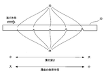
- a groove bottom curvature radius becomes small toward the one end portion in the longitudinal direction of the magnet body
Landscapes
- Engineering & Computer Science (AREA)
- Power Engineering (AREA)
- Manufacturing & Machinery (AREA)
- Life Sciences & Earth Sciences (AREA)
- Forests & Forestry (AREA)
- Mechanical Engineering (AREA)
- Permanent Field Magnets Of Synchronous Machinery (AREA)
Abstract
Description
Claims (2)
- 磁石体をその長手方向に間隔を置いて配置される複数の割断予定部位で割断する、界磁極用磁石体を構成する磁石片の製造方法において、
前記複数の割断予定部位のそれぞれに、前記磁石体の長手方向の一方の端部に近づくにつれて深くなる溝が形成された前記磁石体を、前記一方の端部に近い前記割断予定部位から順に割断する割断工程を含む、
製造方法。 - 請求項1に記載の製造方法であって、
前記溝は、前記磁石体の長手方向の一方の端部に近づくにつれて溝底の曲率半径が小さくなる、
製造方法。
Priority Applications (4)
| Application Number | Priority Date | Filing Date | Title |
|---|---|---|---|
| EP13743531.9A EP2811628B1 (en) | 2012-02-01 | 2013-01-30 | Method for manufacturing magnet pieces for forming field-pole magnets |
| CN201380005956.4A CN104067489B (zh) | 2012-02-01 | 2013-01-30 | 构成场磁极用磁体的磁体片的制造方法 |
| JP2013556433A JP5761384B2 (ja) | 2012-02-01 | 2013-01-30 | 界磁極用磁石体を構成する磁石片の製造方法 |
| US14/374,951 US9251951B2 (en) | 2012-02-01 | 2013-01-30 | Method of manufacturing magnet segment of field pole magnet body |
Applications Claiming Priority (2)
| Application Number | Priority Date | Filing Date | Title |
|---|---|---|---|
| JP2012-019634 | 2012-02-01 | ||
| JP2012019634 | 2012-02-01 |
Publications (1)
| Publication Number | Publication Date |
|---|---|
| WO2013115224A1 true WO2013115224A1 (ja) | 2013-08-08 |
Family
ID=48905257
Family Applications (1)
| Application Number | Title | Priority Date | Filing Date |
|---|---|---|---|
| PCT/JP2013/051999 Ceased WO2013115224A1 (ja) | 2012-02-01 | 2013-01-30 | 界磁極用磁石体を構成する磁石片の製造方法 |
Country Status (4)
| Country | Link |
|---|---|
| US (1) | US9251951B2 (ja) |
| EP (1) | EP2811628B1 (ja) |
| JP (1) | JP5761384B2 (ja) |
| WO (1) | WO2013115224A1 (ja) |
Families Citing this family (8)
| Publication number | Priority date | Publication date | Assignee | Title |
|---|---|---|---|---|
| JP5494791B2 (ja) * | 2011-03-31 | 2014-05-21 | トヨタ自動車株式会社 | 割断方法、ロータ製造方法、及び割断装置 |
| JP5929153B2 (ja) * | 2011-12-14 | 2016-06-01 | 日産自動車株式会社 | 界磁極用磁石体の製造装置およびその製造方法 |
| US10279504B2 (en) * | 2013-10-09 | 2019-05-07 | Nissan Motor Co., Ltd. | Manufacture method and manufacturing device for manufacturing magnet piece constituting magnet body for field pole disposed on rotating electric machine |
| CN105848841B (zh) * | 2013-12-27 | 2017-07-28 | 旭硝子株式会社 | 脆性板的加工方法及脆性板的加工装置 |
| DK179948B1 (en) * | 2017-05-16 | 2019-10-22 | Apple Inc. | Recording and sending Emoji |
| WO2019026586A1 (ja) * | 2017-08-01 | 2019-02-07 | 坂東機工株式会社 | ガラス板の折割機械 |
| US11004586B2 (en) | 2017-09-15 | 2021-05-11 | Siemens Gamesa Renewable Energy A/S | Permanent magnet for a permanent magnet machine |
| EP3457532B1 (en) * | 2017-09-15 | 2023-02-01 | Siemens Gamesa Renewable Energy A/S | Permanent magnet for a permanent magnet machine |
Citations (6)
| Publication number | Priority date | Publication date | Assignee | Title |
|---|---|---|---|---|
| JP2009033958A (ja) | 2007-06-29 | 2009-02-12 | Nissan Motor Co Ltd | 界磁極用磁石体、この界磁用磁石体の作製方法、及び永久磁石型回転電機 |
| WO2010038748A1 (ja) * | 2008-10-02 | 2010-04-08 | 日産自動車株式会社 | 界磁極用磁石体、この界磁用磁石体の作製方法、及び永久磁石型回転電機 |
| JP2010259231A (ja) * | 2009-04-24 | 2010-11-11 | Nissan Motor Co Ltd | 界磁極用永久磁石及びその製造方法並びに界磁極用永久磁石を備える永久磁石型回転電機 |
| WO2011004490A1 (ja) * | 2009-07-10 | 2011-01-13 | トヨタ自動車株式会社 | 磁石割断装置及び磁石の割断方法 |
| JP2011125105A (ja) * | 2009-12-09 | 2011-06-23 | Toyota Motor Corp | 割断磁石を備えたモータとその製造方法 |
| WO2011145433A1 (ja) * | 2010-05-19 | 2011-11-24 | 日産自動車株式会社 | 回転電機に配設される永久磁石およびその製造方法 |
Family Cites Families (9)
| Publication number | Priority date | Publication date | Assignee | Title |
|---|---|---|---|---|
| US3564958A (en) * | 1967-07-17 | 1971-02-23 | Leesona Corp | Yarn handling apparatus |
| NL7907115A (nl) * | 1979-09-25 | 1981-03-27 | Philips Nv | Werkwijze voor het vervaardigen van een permanente magneet ter plaatsing in een luchtspleet van een transformatorkern. |
| SE0201945D0 (sv) * | 2002-06-25 | 2002-06-25 | Nyfors Teknologi Ab | An apparatus and a method for cleaving thin rods |
| JP4497198B2 (ja) * | 2007-12-06 | 2010-07-07 | トヨタ自動車株式会社 | 永久磁石とその製造方法、およびロータとipmモータ |
| WO2011158710A1 (ja) * | 2010-06-17 | 2011-12-22 | 日産自動車株式会社 | 回転電機に配設される永久磁石の製造装置およびその製造方法 |
| CN102754307B (zh) * | 2011-02-02 | 2015-05-06 | 丰田自动车株式会社 | 永久磁铁、用于马达的转子或定子、旋转电机 |
| JP6393019B2 (ja) * | 2011-09-26 | 2018-09-19 | 日産自動車株式会社 | 界磁極用磁石体の製造装置およびその製造方法 |
| CN104396127B (zh) * | 2012-07-02 | 2016-10-12 | 日产自动车株式会社 | 构成场磁极用磁体的磁体片的制造装置及其制造方法 |
| US20140263523A1 (en) * | 2013-03-14 | 2014-09-18 | David L. Allyn | Devices and methods for breaking and storing a safety razor blade |
-
2013
- 2013-01-30 JP JP2013556433A patent/JP5761384B2/ja active Active
- 2013-01-30 EP EP13743531.9A patent/EP2811628B1/en active Active
- 2013-01-30 US US14/374,951 patent/US9251951B2/en active Active
- 2013-01-30 WO PCT/JP2013/051999 patent/WO2013115224A1/ja not_active Ceased
Patent Citations (6)
| Publication number | Priority date | Publication date | Assignee | Title |
|---|---|---|---|---|
| JP2009033958A (ja) | 2007-06-29 | 2009-02-12 | Nissan Motor Co Ltd | 界磁極用磁石体、この界磁用磁石体の作製方法、及び永久磁石型回転電機 |
| WO2010038748A1 (ja) * | 2008-10-02 | 2010-04-08 | 日産自動車株式会社 | 界磁極用磁石体、この界磁用磁石体の作製方法、及び永久磁石型回転電機 |
| JP2010259231A (ja) * | 2009-04-24 | 2010-11-11 | Nissan Motor Co Ltd | 界磁極用永久磁石及びその製造方法並びに界磁極用永久磁石を備える永久磁石型回転電機 |
| WO2011004490A1 (ja) * | 2009-07-10 | 2011-01-13 | トヨタ自動車株式会社 | 磁石割断装置及び磁石の割断方法 |
| JP2011125105A (ja) * | 2009-12-09 | 2011-06-23 | Toyota Motor Corp | 割断磁石を備えたモータとその製造方法 |
| WO2011145433A1 (ja) * | 2010-05-19 | 2011-11-24 | 日産自動車株式会社 | 回転電機に配設される永久磁石およびその製造方法 |
Non-Patent Citations (1)
| Title |
|---|
| See also references of EP2811628A4 * |
Also Published As
| Publication number | Publication date |
|---|---|
| JP5761384B2 (ja) | 2015-08-12 |
| EP2811628A4 (en) | 2014-12-24 |
| CN104067489A (zh) | 2014-09-24 |
| JPWO2013115224A1 (ja) | 2015-05-11 |
| US9251951B2 (en) | 2016-02-02 |
| US20150034691A1 (en) | 2015-02-05 |
| EP2811628A1 (en) | 2014-12-10 |
| EP2811628B1 (en) | 2015-11-18 |
Similar Documents
| Publication | Publication Date | Title |
|---|---|---|
| JP5761384B2 (ja) | 界磁極用磁石体を構成する磁石片の製造方法 | |
| JP5446428B2 (ja) | 界磁極用永久磁石及びその製造方法並びに界磁極用永久磁石を備える永久磁石型回転電機 | |
| JP6393019B2 (ja) | 界磁極用磁石体の製造装置およびその製造方法 | |
| JP5614096B2 (ja) | 回転電機のロータコアに埋込まれる永久磁石およびその製造方法 | |
| EP2584681B1 (en) | Method for manufacturing permanent magnets for a dynamo-electric machine | |
| CN102754307B (zh) | 永久磁铁、用于马达的转子或定子、旋转电机 | |
| CN104868623B (zh) | 电动机的转子、电动机以及电动机的转子的制造方法 | |
| JP5360224B2 (ja) | 電動機の回転子の製造方法 | |
| CN104067489B (zh) | 构成场磁极用磁体的磁体片的制造方法 | |
| JP5994280B2 (ja) | 界磁極用磁石体を構成する磁石片の製造方法および製造装置 | |
| JP5761383B2 (ja) | 界磁極用磁石体の製造方法 | |
| JP5849774B2 (ja) | 回転電機に配設される界磁極用磁石体を構成する磁石片を、永久磁石体を割断して製造する割断方法及び割断装置 | |
| JP5919888B2 (ja) | 回転電機に配設される界磁極用磁石体を構成する磁石片を、永久磁石体を割断して製造する割断方法及び割断装置 | |
| JP5906768B2 (ja) | 界磁極用磁石体を構成する磁石片の製造装置及びその製造方法 | |
| JP5929310B2 (ja) | 界磁極用磁石体を構成する磁石片の製造方法 | |
| WO2013115301A1 (ja) | 界磁極用磁石体を構成する磁石片の製造装置 | |
| JP6164093B2 (ja) | 永久磁石の製造方法 | |
| JP2014023209A (ja) | 界磁極用磁石体を構成する磁石片の製造装置及びその製造方法 |
Legal Events
| Date | Code | Title | Description |
|---|---|---|---|
| 121 | Ep: the epo has been informed by wipo that ep was designated in this application |
Ref document number: 13743531 Country of ref document: EP Kind code of ref document: A1 |
|
| WWE | Wipo information: entry into national phase |
Ref document number: 2013743531 Country of ref document: EP |
|
| ENP | Entry into the national phase |
Ref document number: 2013556433 Country of ref document: JP Kind code of ref document: A |
|
| WWE | Wipo information: entry into national phase |
Ref document number: 14374951 Country of ref document: US |
|
| NENP | Non-entry into the national phase |
Ref country code: DE |