WO2013115236A1 - 太陽光発電システム及び故障検知方法 - Google Patents
太陽光発電システム及び故障検知方法 Download PDFInfo
- Publication number
- WO2013115236A1 WO2013115236A1 PCT/JP2013/052020 JP2013052020W WO2013115236A1 WO 2013115236 A1 WO2013115236 A1 WO 2013115236A1 JP 2013052020 W JP2013052020 W JP 2013052020W WO 2013115236 A1 WO2013115236 A1 WO 2013115236A1
- Authority
- WO
- WIPO (PCT)
- Prior art keywords
- solar cell
- signal
- bypass diode
- open mode
- solar
- Prior art date
- Legal status (The legal status is an assumption and is not a legal conclusion. Google has not performed a legal analysis and makes no representation as to the accuracy of the status listed.)
- Ceased
Links
Images


Classifications
-
- H—ELECTRICITY
- H02—GENERATION; CONVERSION OR DISTRIBUTION OF ELECTRIC POWER
- H02S—GENERATION OF ELECTRIC POWER BY CONVERSION OF INFRARED RADIATION, VISIBLE LIGHT OR ULTRAVIOLET LIGHT, e.g. USING PHOTOVOLTAIC [PV] MODULES
- H02S50/00—Monitoring or testing of PV systems, e.g. load balancing or fault identification
-
- G—PHYSICS
- G01—MEASURING; TESTING
- G01R—MEASURING ELECTRIC VARIABLES; MEASURING MAGNETIC VARIABLES
- G01R31/00—Arrangements for testing electric properties; Arrangements for locating electric faults; Arrangements for electrical testing characterised by what is being tested not provided for elsewhere
- G01R31/26—Testing of individual semiconductor devices
-
- H—ELECTRICITY
- H02—GENERATION; CONVERSION OR DISTRIBUTION OF ELECTRIC POWER
- H02S—GENERATION OF ELECTRIC POWER BY CONVERSION OF INFRARED RADIATION, VISIBLE LIGHT OR ULTRAVIOLET LIGHT, e.g. USING PHOTOVOLTAIC [PV] MODULES
- H02S50/00—Monitoring or testing of PV systems, e.g. load balancing or fault identification
- H02S50/10—Testing of PV devices, e.g. of PV modules or single PV cells
-
- H—ELECTRICITY
- H10—SEMICONDUCTOR DEVICES; ELECTRIC SOLID-STATE DEVICES NOT OTHERWISE PROVIDED FOR
- H10F—INORGANIC SEMICONDUCTOR DEVICES SENSITIVE TO INFRARED RADIATION, LIGHT, ELECTROMAGNETIC RADIATION OF SHORTER WAVELENGTH OR CORPUSCULAR RADIATION
- H10F19/00—Integrated devices, or assemblies of multiple devices, comprising at least one photovoltaic cell covered by group H10F10/00, e.g. photovoltaic modules
- H10F19/70—Integrated devices, or assemblies of multiple devices, comprising at least one photovoltaic cell covered by group H10F10/00, e.g. photovoltaic modules comprising bypass diodes
-
- H—ELECTRICITY
- H10—SEMICONDUCTOR DEVICES; ELECTRIC SOLID-STATE DEVICES NOT OTHERWISE PROVIDED FOR
- H10F—INORGANIC SEMICONDUCTOR DEVICES SENSITIVE TO INFRARED RADIATION, LIGHT, ELECTROMAGNETIC RADIATION OF SHORTER WAVELENGTH OR CORPUSCULAR RADIATION
- H10F77/00—Constructional details of devices covered by this subclass
- H10F77/95—Circuit arrangements
- H10F77/953—Circuit arrangements for devices having potential barriers
- H10F77/955—Circuit arrangements for devices having potential barriers for photovoltaic devices
-
- Y—GENERAL TAGGING OF NEW TECHNOLOGICAL DEVELOPMENTS; GENERAL TAGGING OF CROSS-SECTIONAL TECHNOLOGIES SPANNING OVER SEVERAL SECTIONS OF THE IPC; TECHNICAL SUBJECTS COVERED BY FORMER USPC CROSS-REFERENCE ART COLLECTIONS [XRACs] AND DIGESTS
- Y02—TECHNOLOGIES OR APPLICATIONS FOR MITIGATION OR ADAPTATION AGAINST CLIMATE CHANGE
- Y02B—CLIMATE CHANGE MITIGATION TECHNOLOGIES RELATED TO BUILDINGS, e.g. HOUSING, HOUSE APPLIANCES OR RELATED END-USER APPLICATIONS
- Y02B10/00—Integration of renewable energy sources in buildings
- Y02B10/10—Photovoltaic [PV]
-
- Y—GENERAL TAGGING OF NEW TECHNOLOGICAL DEVELOPMENTS; GENERAL TAGGING OF CROSS-SECTIONAL TECHNOLOGIES SPANNING OVER SEVERAL SECTIONS OF THE IPC; TECHNICAL SUBJECTS COVERED BY FORMER USPC CROSS-REFERENCE ART COLLECTIONS [XRACs] AND DIGESTS
- Y02—TECHNOLOGIES OR APPLICATIONS FOR MITIGATION OR ADAPTATION AGAINST CLIMATE CHANGE
- Y02E—REDUCTION OF GREENHOUSE GAS [GHG] EMISSIONS, RELATED TO ENERGY GENERATION, TRANSMISSION OR DISTRIBUTION
- Y02E10/00—Energy generation through renewable energy sources
- Y02E10/50—Photovoltaic [PV] energy
Definitions
- the present invention relates to a photovoltaic power generation system and a failure detection method.
- a reverse voltage may be applied to the solar cell due to, for example, variations in characteristics, fluctuations in solar radiation intensity, and the like, and this reverse voltage increases. In such a case, there is a risk that the solar cell may generate heat and be damaged. Therefore, as a conventional solar cell module, one in which a bypass diode is connected in parallel to the solar cell and an excessive reverse voltage is suppressed from being applied to the solar cell is known (for example, see Patent Document 1). .
- an object of the present invention is to provide a photovoltaic power generation system and a failure detection method for detecting an open mode failure of a bypass diode.
- a solar power generation system includes a solar cell that generates power using sunlight, a bypass diode connected in parallel to the solar cell, a detection unit that detects an open mode failure of the bypass diode,
- the solar cell module which comprises.
- the failure detection method includes a detection step of detecting an open mode failure of a bypass diode connected in parallel to a solar cell that generates power using sunlight.
- An open mode failure of the bypass diode is detected when a predetermined reverse voltage value is applied to the battery, and the predetermined reverse voltage value is determined from the voltage drop value of the solar cell when the maximum current value flows through the bypass diode. Is also a large voltage drop value.
- the solar cell is shielded by the shielding plate, the temperature of the light shielding portion of the solar cell is detected by the thermal paper integrated with the shielding plate, and hot spot heat (abnormal heat generation) is detected in the shielding portion of the solar cell.
- production it determines that the electric current is not flowing into the bypass diode and can consider the technique which determines with this that the bypass diode has failed in open mode.
- the solar cell unit is installed at a high place such as a roof.
- the work is actually complicated and is not suitable for daily inspection from the viewpoint of safety and cost.
- bypass diode it may be difficult to determine whether or not the bypass diode is broken for the following reason. That is, even when the bypass diode does not have an open mode failure, when the solar cell is shielded from light, a certain amount of reverse voltage is applied to the solar cell, and heat generation of the solar cell may be detected.
- the degree of heat generation cannot be generally predicted because it depends on the solar radiation intensity, the light shielding state, the current density of the solar cell, the heat radiation state of the solar cell, the shunt resistance component of the solar cell, and the like. Therefore, it becomes extremely difficult to distinguish between heat generation in the normal range and heat generation due to a failure of the bypass diode, and there is a possibility that an open mode failure of the bypass diode cannot be accurately detected.
- bypass diode when the open mode failure of the bypass diode occurs, prompt action is required to prevent the solar cell from overheating and damage.
- the failure cannot be detected accurately, and there is a concern about the delay of the countermeasure.
- the normally functioning bypass diode is also determined to be a malfunction, and the power generation capability of the solar cell is unnecessary. There is a risk that it will be reduced or hindered.
- An aspect of the present invention has been made in view of the above circumstances, and an object thereof is to make it possible to easily improve the reliability while ensuring the power generation capability.
- a solar cell module included in a solar cell system includes a solar cell that generates power using sunlight, a bypass diode connected in parallel to the solar cell, and a bypass A detection unit that detects an open mode failure of the diode, and a blocking unit that blocks the current of the solar cell when the detection unit detects an open mode failure of the bypass diode.
- this solar cell module it is possible to avoid applying a high reverse voltage to the solar cell by a bypass diode during normal operation.
- the current of the solar cell is not interrupted immediately, and the bypass diode provides an effect that can be generated in the other part of the solar cell. The decrease can be suppressed.
- the bypass diode fails in the open mode, the open mode failure is detected by the detection unit, and the current of the solar cell is blocked by the blocking unit, so that the solar cell can be prevented from being heated or damaged. That is, the countermeasure against the open mode failure of the bypass diode is automatically implemented without requiring any special work, and damage beyond the open mode failure is suppressed.
- a reverse voltage is applied to the solar cell means that the potential of the positive electrode with respect to the negative electrode of the solar cell is in a low state (hereinafter the same).
- the detection unit detects an open mode failure of the bypass diode when a predetermined reverse voltage value is applied to the solar cell, and the predetermined reverse voltage value is obtained when a current of the maximum current value flows through the bypass diode.
- the voltage drop value is preferably larger than the voltage drop value of the solar cell. In this case, the open mode failure of the bypass diode can be accurately detected by the detection unit.
- the maximum current value is a short-circuit current value of the solar cell when the solar cell is irradiated with sunlight having a solar constant amount of solar radiation.
- the open mode failure of the bypass diode can be detected with higher accuracy by the detector.
- the detection unit when the open mode failure of the bypass diode is detected by the detection unit, the detection unit includes a signal transmission device that transmits a signal including a failure signal, and a signal reception device that receives a signal from the signal transmission device. It is preferable to interrupt the current of the solar cell in response to reception of the signal by the receiving device. In this case, when the bypass diode fails in the open mode, the current of the solar cell can be suitably interrupted by the interrupting unit.
- the signal transmission device transmits a signal further including an eigenvalue signal for identifying the solar cell module in which the bypass diode has failed in the open mode.
- a signal further including an eigenvalue signal for identifying the solar cell module in which the bypass diode has failed in the open mode.
- a display device that displays information on the open mode failure of the bypass diode in response to reception of a signal by the signal receiving device.
- the open mode failure can be notified by being displayed on the display device.
- a photovoltaic power generation system includes a solar cell that generates power using sunlight, a bypass diode connected in parallel to the solar cell, and a detection unit that detects an open mode failure of the bypass diode.
- a solar power generation system comprising at least one solar cell string formed by connecting a plurality of solar cell modules connected in series, and when the detector detects an open mode failure of the bypass diode, the solar cell string The interruption part which interrupts the electric current of is provided.
- This solar power generation system also has the same effects as the solar cell module. That is, it is possible to avoid applying a high reverse voltage to the solar cell during normal times and to suppress a decrease in power generation capacity. Furthermore, when the bypass diode fails in the open mode, the open mode failure is detected by the detection unit, and the current of the solar cell is blocked by the blocking unit, so that the solar cell can be prevented from being heated or damaged. Therefore, it is possible to easily improve the reliability while ensuring the power generation capacity.
- the detection unit detects an open mode failure of the bypass diode when a predetermined reverse voltage value is applied to the solar cell, and the predetermined reverse voltage value is the maximum current value of the bypass diode.
- the voltage drop value is preferably larger than the voltage drop value of the solar cell when the current flows. Even in this case, the open mode failure of the bypass diode can be accurately detected by the detection unit.
- the maximum current value is preferably a short-circuit current value of the solar cell when the solar cell is irradiated with sunlight having a solar constant amount on the entire surface. Even in this case, as described above, the open mode failure of the bypass diode can be detected with higher accuracy by the detector.
- the detection unit when the open mode failure of the bypass diode is detected by the detection unit, the detection unit includes a signal transmission device that transmits a signal including a failure signal, and a signal reception device that receives a signal from the signal transmission device. It is preferable to interrupt the current of the solar cell string in response to reception of the signal by the receiving device. Even in this case, when the bypass diode fails in the open mode, the current of the solar cell can be suitably cut off by the cut-off unit.
- the signal transmission device transmits a signal further including a unique value signal for identifying the solar cell module in which the bypass diode has failed in the open mode.
- the cutoff unit receives the unique value of the signal. It is preferable to interrupt the current of the solar cell string to which the solar cell module corresponding to the signal belongs. In this case, the current is interrupted for the solar cell string of the solar cell module that has failed in the open mode.
- a display device that displays information on the open mode failure of the bypass diode in response to reception of a signal by the signal receiving device.
- the open mode failure can be notified by being displayed on the display device.
- the signal receiving device includes a display device that displays information related to the open mode failure of the bypass diode in response to reception of the signal by the signal receiving device.
- the blocking unit blocks the current of the solar cell string to which the solar cell module corresponding to the eigenvalue signal of the signal belongs, and the display device
- the display device When a signal is received by the receiving device, it is preferable to display information including specific information for specifying the solar cell module corresponding to the eigenvalue signal of the signal.
- the current is interrupted for the solar cell string of the solar cell module that has failed in the open mode.
- blocking part, the said signal transmission apparatus, the said signal receiving apparatus, and the said display apparatus may be mechanically integrated with a solar cell module, or may be a different body.
- the bypass diode may be difficult to determine whether or not the bypass diode has failed for the following reason. That is, even when the bypass diode does not have an open mode failure, when the solar cell is shielded from light, a certain amount of reverse voltage is applied to the solar cell, and heat generation of the solar cell may be detected.
- the degree of heat generation cannot be generally predicted because it depends on the solar radiation intensity, the light shielding state, the current density of the solar cell, the heat radiation state of the solar cell, the shunt resistance component of the solar cell, and the like. Therefore, it becomes extremely difficult to distinguish between heat generation in the normal range and heat generation due to a failure of the bypass diode, and there is a possibility that an open mode failure of the bypass diode cannot be accurately detected.
- An aspect of the present invention has been made in view of the above circumstances, and an object thereof is to provide a failure detection device and a failure detection method capable of accurately detecting an open mode failure of a bypass diode.
- the present inventors have conducted intensive studies. As a result, when the bypass diode fails in the open mode, the voltage drop value of the solar cell when the maximum current value flows through the bypass diode is more than The knowledge that a large voltage drop value is applied to the solar cell was obtained. Therefore, based on such knowledge, it has been found that an open mode failure of a bypass diode can be detected with high accuracy, and the present invention has been completed.
- a failure detection device included in a solar cell system includes a solar cell that generates power using sunlight, and a bypass diode connected in parallel to the solar cell.
- a failure detection device for detecting a failure in the apparatus comprising a detection unit for detecting an open mode failure of the bypass diode, the detection unit being an open mode failure of the bypass diode when a predetermined reverse voltage value is applied to the solar cell
- the predetermined reverse voltage value is a voltage drop value larger than the voltage drop value of the solar cell when the maximum current value flows through the bypass diode.
- a reverse voltage is applied to the solar cell means that the potential of the positive electrode with respect to the negative electrode of the solar cell is in a low state (hereinafter the same).
- the maximum current value is a short-circuit current value of the solar cell when the solar cell is irradiated with sunlight having a solar constant amount of solar radiation.
- an open mode failure of the bypass diode can be detected with higher accuracy. This is because the above-mentioned maximum current value flowing through the bypass diode is further found out that it is a short-circuit current value of the solar cell when the solar cell is irradiated with sunlight having the solar constant on the entire surface.
- a signal transmission device that transmits a signal including a failure signal
- a signal reception device that receives a signal from the signal transmission device, and reception of a signal by the signal reception device
- a display device that displays information regarding the open mode failure of the bypass diode. In this case, the open mode failure can be notified by being displayed on the display device.
- the signal transmission device transmits a signal further including an eigenvalue signal for identifying the solar cell module in which the bypass diode has failed in the open mode.
- a signal further including an eigenvalue signal for identifying the solar cell module in which the bypass diode has failed in the open mode.
- a failure detection device included in a solar cell system includes a solar cell that generates power using sunlight, and a bypass diode connected in parallel to the solar cell.
- a failure detection device that detects a failure in a solar power generation system including at least one solar cell string that is connected in series, and includes a detection unit that detects an open mode failure of a bypass diode, An open mode failure of the bypass diode is detected when a predetermined reverse voltage value is applied to the solar cell, and the predetermined reverse voltage value is a voltage drop of the solar cell when the maximum current value flows through the bypass diode. The voltage drop value is larger than the value.
- the above knowledge can be suitably applied to the open mode failure of the bypass diode, and the open mode failure can be accurately detected.
- the maximum current value is a short-circuit current value of the solar cell when the solar cell is irradiated with sunlight having a solar constant amount of solar radiation.
- an open mode failure of the bypass diode can be detected with higher accuracy.
- a signal transmission device that transmits a signal including a failure signal
- a signal reception device that receives a signal from the signal transmission device, and reception of a signal by the signal reception device
- a display device that displays information regarding the open mode failure of the bypass diode. In this case, the open mode failure can be notified by being displayed on the display device.
- the signal transmission device transmits a signal further including an eigenvalue signal for identifying the solar cell module in which the bypass diode has failed in the open mode, and when the display device receives the signal by the signal reception device, the eigenvalue of the signal It is preferable to display information including specific information for specifying the solar cell module corresponding to the signal. In this case, it becomes possible to identify the solar cell module in which the bypass diode has failed in the open mode by the identification information displayed on the display device.
- the failure detection method includes a detection step of detecting an open mode failure of a bypass diode connected in parallel to a solar cell that generates power using sunlight.
- An open mode failure of the bypass diode is detected when a predetermined reverse voltage value is applied to the battery, and the predetermined reverse voltage value is determined from the voltage drop value of the solar cell when the maximum current value flows through the bypass diode. Is also a large voltage drop value.
- the above knowledge can be suitably applied to the open mode failure of the bypass diode, and the open mode failure can be accurately detected.
- the maximum current value is a short-circuit current value of the solar cell when the solar cell is irradiated with sunlight having a solar constant amount of solar radiation.
- an open mode failure of the bypass diode can be detected with higher accuracy.
- a signal transmission step for transmitting a signal including a failure signal
- a signal reception step for receiving a signal transmitted by the signal transmission step
- a signal by the signal reception step And a display step of displaying information related to the open mode failure of the bypass diode in response to the reception.
- an open mode failure can be displayed and notified in the display process.
- the signal transmission step it is preferable to transmit a signal further including an eigenvalue signal for identifying the solar cell module including the bypass diode that has failed in the open mode.
- a signal further including an eigenvalue signal for identifying the solar cell module including the bypass diode that has failed in the open mode.
- each of the detection unit, the signal transmission device, the signal reception device, and the display device may be mechanically integrated with the solar cell module or may be separate.
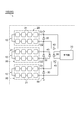
- FIG. 1 is a configuration diagram illustrating a solar power generation system including a failure detection apparatus according to the first embodiment
- FIG. 2 is a configuration diagram of a solar cell module in the solar power generation system of FIG.
- the failure detection device 90 of the present embodiment is for detecting a failure in the solar cell module 100, and includes an LED (Light Emitting Diode) 40 and a light receiving element 60 as a detection unit, a signal A transmitter 70 as a transmission device, a reception unit 151 as a signal reception device, and a switch 140 and a switch control unit 152 as a cutoff unit are provided.
- the failure detection device 90 will be described together with the solar cell module 100.
- the solar power generation system 1 is a power generation system that generates power using solar energy, and is installed in a high place such as a roof, for example, and is of a system linkage type having an output voltage of 200 V or more.
- the solar power generation system 1 includes a solar cell array 110 and a power conditioner 120.
- the solar cell array 110 converts solar energy into electric energy and supplies it to the power conditioner 120 as a DC output.
- the solar cell array 110 includes at least one solar cell string 130 in which a plurality of solar cell modules 100 are connected in series. Here, eight solar cell modules 100 are connected in series to each other to form a solar cell string 130, and two solar cell strings 130 are connected to each other in parallel to form a solar cell array 110.
- This solar cell array 110 is connected to the power conditioner 120 via a switch 140.
- the power conditioner 120 converts the DC output supplied from the solar cell array 110 into an AC output, and supplies the AC output to a subsequent power system (for example, a commercial power system).
- the power conditioner 120 has an operating voltage control function for controlling the operating voltage of the solar cell array 110 so that the maximum output of the solar cell array 110 can be obtained, and safely stops the system when an abnormality in the power system is detected. System protection function.
- the power conditioner 120 may be a transformer insulation type having an insulation transformer or a transformerless (non-insulation) type.
- the switch 140 is a switch that controls electrical connection between the solar cell array 110 and the power conditioner 120.
- the switch 140 can be of any configuration as long as it cuts off the current.
- an FET Field Effect Transistor
- IGBT Insulated Gate
- Bipolar transistors Bipolar transistors
- Other electromagnetic switches such as mechanical switches can be used.
- the switch 140 is normally closed to connect the solar cell array 110 and the power conditioner 120 to each other, while being open when the bypass diode 30 is in an open failure, the switches 140 are disconnected from each other (details will be described later). .
- the solar cell module 100 is configured in a panel shape and includes a plurality (here, three) solar cell units 10 connected in series with each other as shown in FIG.
- Each of the plurality of solar cell units 10 includes a solar cell cluster (solar cell) 20, a bypass diode 30, and an LED 40.
- the solar battery cluster 20 includes a plurality of solar battery cells 21 connected in series with each other, and generates power using sunlight.
- the plurality of solar cells 21 are fixed to the aluminum frame in a state of being arranged in a matrix, and the light receiving surface side is covered with tempered glass.
- the bypass diode 30 is connected in parallel to the solar cell cluster 20.
- a Schottky barrier diode is used in order to reduce the forward voltage and shorten the reverse recovery time.
- the bypass diode 30 is provided such that a current flows when a reverse voltage is applied to the solar cell cluster 20, and the forward direction thereof is the forward direction of the equivalent parasitic diode of the solar cell 21 in the solar cell cluster 20. On the other hand, it is the opposite direction.
- the cathode side of the bypass diode 30 is connected to the positive electrode side of the solar cell cluster 20 on the electric circuit 50 connecting the solar cell clusters 20 in series.
- the anode side of the bypass diode 30 is connected to the negative electrode side of the solar cell cluster 20 on the electric circuit 50.
- the LED 40 is a light emitting element connected in parallel to the solar cell cluster 20 and the bypass diode 30, and constitutes a detection unit that detects an open mode failure of the bypass diode 30.
- the LED 40 has a forward direction opposite to the forward direction of the equivalent parasitic diode of the solar battery cell 21 in the solar battery cluster 20, and emits light when a predetermined reverse voltage value is applied to the solar battery cluster 20. Is provided.
- the predetermined reverse voltage value is set by providing an IV curve (current voltage curve) characteristic of the LED 40 as described in detail below, for example, in order to cause the LED 40 to emit light when the bypass diode 30 fails in the open mode. ing.
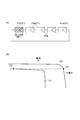
- FIG. 3A is a graph showing individually the IV curve characteristics of each element in the solar cell unit
- FIG. 3B is a graph showing the synthesized IV curve characteristics of each element in the solar cell unit.
- the maximum current value is a short circuit current value when the solar cell cluster 20 is exposed to the maximum possible solar radiation intensity, and is a short circuit corresponding to the solar constant that is the solar radiation intensity before being subjected to absorption and scattering by the atmosphere. It can be regarded as a current value.
- the maximum current value is the solar cell cluster with sunlight with a solar constant solar radiation amount. 20 can be the short-circuit current value of the solar cell when irradiated on the entire surface, and the value of the following formula (1) can be used as the maximum current value.
- the “entire surface” allows manufacturing and design errors, and includes substantially the entire surface or substantially the entire surface.
- the voltage drop value Vb is used as a reference, a voltage drop value larger than this is set as a predetermined reverse voltage value, and current flows when the predetermined reverse voltage value is applied to the solar cell cluster 20.
- the LED 40 having the IV curve characteristic that emits light is employed.
- the LED 40 is configured by a diode having an IV curve characteristic in which a forward current flows when the voltage drop value is larger than the IV curve characteristic of the bypass diode 30.
- the voltage drop value may slightly change depending on the environmental temperature of the diode, in order to avoid malfunction, there is a difference ⁇ V between the voltage drop value Vb and the predetermined reverse voltage value. Is preferably provided. Since the difference ⁇ V is a malfunction prevention margin with respect to an operation threshold of less than 1V, a small value of that level can be adopted as the difference ⁇ V. This difference ⁇ V can further avoid system reliability.
- the cathode side of the LED 40 is connected to the connection point O 1 between the positive electrode side of the solar cell cluster 20 and the bypass diode 30 on the electric circuit 50.
- the anode side of the LED 40 is connected to the connection point O ⁇ b> 2 between the negative electrode side of the solar cell cluster 20 and the bypass diode 30 on the electric circuit 50.
- the solar cell module 100 includes a light receiving element 60 and a transmitter 70.
- the light receiving element 60 receives LED light emitted by at least one LED 40 and constitutes a detection unit that detects an open mode failure of the bypass diode 30.
- the light receiving element 60 is disposed (optically coupled) so that the LED light from each LED 40 can be suitably received.
- the light receiving element 60 is disposed close to each LED 40.
- the transmitter 70 transmits a signal including a failure signal related to the open mode failure of the bypass diode 30 to the receiving unit 151 described later.
- the present embodiment includes a controller 150 for controlling the flow of current in the solar cell array 110.
- the controller 150 includes a reception unit 151 and a switch control unit 152.
- the receiving unit 151 receives a signal transmitted by the transmitter 70 (see FIG. 2) of the solar cell module 100.
- the switch control unit 152 blocks the current (charge flow) of the solar cell array 110 in response to reception of a signal by the receiving unit 151. Specifically, when the signal from the transmitter 70 is received by the receiving unit 151, the switch control unit 152 controls the switch 140 to be in an open state, disconnecting the solar cell array 110 from the power conditioner 120, The current of the solar cell array 110 is interrupted.
- FIG. 4A is a configuration diagram for explaining the bypass diode
- FIG. 4B is a graph showing the IV curve characteristics of the solar cell cluster for explaining the bypass diode.
- L3 has shown the IV curve characteristic of the high solar radiation solar cell 21a
- L4 has shown the IV curve characteristic of the low solar radiation solar cell 21b.
- the solar cell unit 10 since a plurality of solar cells 21 are connected in series as the solar cell cluster 20, some of the solar cells are caused by characteristic variations among these solar cells 21, differences in solar radiation intensity, and the like. 21 may generate a reverse voltage.
- the total voltage is 0.
- the respective applied voltages are operating points P1 and P2. Therefore, although the high solar radiation solar cell 21a generates power, the low solar solar cell 21b consumes the same power as the power generation, and it is understood that a reverse voltage is applied.
- the bypass diode 30 is connected in parallel to the solar cell cluster 20 to suppress the voltage loss Vloss of the solar cell cluster 20, thereby reducing the voltage loss Vcell of the low solar radiation solar cell 21b. Greatly exceeds the voltage gain Vg.
- Vcell Vloss + Vg (2)
- Vcell Voltage loss of low solar solar cell 21b
- Vloss Voltage loss of solar cell cluster 20
- Vg Voltage gain of solar cell cluster 20
- the reverse voltage applied to the solar cell 21b is applied to the solar cell by the action of the bypass diode 30. It can suppress exceeding the total voltage which generate
- bypass diode 30 fails in an open mode for some reason, a large reverse voltage is applied to the specific solar cell 21 as described above, and there is a risk of heat generation or module damage. It is preferable to block the battery module 100 so that no current flows. On the other hand, when the bypass diode 30 is normal, in order to ensure power generation capability, it is preferable to prevent the solar cell unit 10 or the solar cell module 100 from being erroneously blocked and to make the bypass diode 30 function reliably.
- the bypass diode 30 functions and no current substantially flows through the LED 40. Therefore, the LED 40 does not emit light, the switch 140 remains closed, and the solar cell array 110 is not shut off.
- the failure detection device 90 can detect the open mode failure. That is, since the IV curve of the solar cell unit 10 transitions to the IV curve characteristic L2 in which the LED 40 is dominant, in any one of the plurality of solar cell modules 100, a predetermined reverse voltage (voltage drop value Vb) is applied to the solar cell cluster 20. Is applied to the LED 40, the LED light is emitted from the LED 40, and the LED light from the LED 40 is received by the light receiving element 60, thereby the open mode of the bypass diode 30. A failure is detected (detection process).
- the failure detection device 90 when the LED light is received by the light receiving element 60, a signal is transmitted from the transmitter 70 to the reception unit 151 (signal transmission step), and this signal is received by the reception unit 151 (signal reception). Process). And when the said signal is received by the receiving part 151, the switch 140 is controlled by the switch control part 152 so that it may be in an open state, the solar cell array 110 is cut off from the power conditioner 120 (electric circuit 50), and the result The current of the solar cell array 110 is safely interrupted (interruption process).
- an open mode failure of the bypass diode 30 is detected when a predetermined reverse voltage value is applied to the solar cell cluster 20, and the predetermined reverse voltage value is a maximum current value in the bypass diode 30.
- the voltage drop value is larger than the voltage drop value of the solar cell cluster 20 when the current of?
- the open mode failure of the bypass diode 30 can be detected with high accuracy by utilizing the above characteristics of the solar cell unit 10.
- the maximum current value is the short-circuit current value of the solar cell cluster 20 when the solar cell cluster 20 is irradiated with sunlight having a solar constant solar radiation amount, the open-mode failure of the bypass diode 30 is further increased. It can be detected accurately.
- LED40 and the attendance element 60 are used as a detection part, it replaces with this and the detector (it detects directly whether the predetermined reverse voltage value is applied to the solar cell cluster 20 (for example, a device that detects a potential difference of the solar cell cluster 20 may be used. In this case, a signal is transmitted from the transmitter 70 when the detector detects that a predetermined reverse voltage value is applied to the solar cell cluster 20.
- an open mode failure of the bypass diode 30 can be detected by the LED 40 and the light receiving element 60, and the switch 140 can be controlled by the switch control unit 152 to interrupt the current of the solar cell array 110.
- the current of the solar cell array 110 can be reliably and inexpensively cut off, and the solar cell array 110 can be prevented from being heated or damaged. That is, the countermeasure against the open mode failure of the bypass diode 30 is automatically implemented without requiring any special work, and damage beyond the open mode failure is suppressed.
- the current of the solar cell cluster 20 can be prevented from being interrupted when necessary, and the current of the solar cell cluster 20 can be prevented from being interrupted when unnecessary. Can be easily improved.
- the controller 150 is configured separately and independently.
- the controller 150 may be built in the power conditioner 120.
- a resistor having a predetermined resistance value may be further provided on the electric circuit 51 in which the LED 40 is arranged and parallel to the solar cell cluster 20 and the bypass diode 30. In this case, when the bypass diode 30 is normal and normal, it is possible to reliably prevent the LED 40 from emitting light due to a weak current flowing through the LED 40.
- the failure detection device 90 (failure detection method) of the present embodiment is configured to detect a failure in the solar cell module 100, it is not limited to this. In short, the failure detection device 90 (failure detection method) may be configured to detect a failure in any one of the photovoltaic power generation system 1, the solar cell array 110, the solar cell string 130, and the solar cell module 100.
- the failure detection device 90 of the present embodiment may not include at least one of the transmitter 70, the reception unit 151, the switch 140, and the switch control unit 152.
- the failure detection method of the present embodiment may not include at least one of a signal transmission process, a signal reception process, and a blocking process.
- the switch 140 and the switch control unit 152 as the blocking unit are provided separately from the solar cell module 100 (that is, outside the solar cell module 100).
- the solar cell module 100 may be mounted (that is, may be provided inside the solar cell module 100).
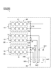
- FIG. 5 is a configuration diagram showing a photovoltaic power generation system including a failure detection apparatus according to the second embodiment.
- the main difference between the present embodiment and the first embodiment is that the first embodiment cuts off the current in units of the solar cell array 110 while the current is cut off in units of the solar cell string 130.
- eigenvalue signals for example, signals related to module numbers, etc.
- each transmitter 70 transmits a signal further including an eigenvalue signal for identifying the solar cell module 100 in which the bypass diode 30 has failed in the open mode.
- each of the solar cell strings 130 in the photovoltaic power generation system 2 is connected to the power conditioner 120 via the switch 140.
- the switch controller 152 upon receiving a signal from the transmitter 70 by the receiver 151 reads the eigenvalues signal from the received signal, the solar cell string 130 in which the solar cell module 100 which correspond to the eigenvalues signal of the signal Is identified. Then, the switch control unit 152 causes the open state by controlling the switch 140 provided to a specific solar cell string 130, the solution to the column this particular solar cell string 130 from power conditioner 120, thereby, the The current of the solar cell string 130 is cut off.
- the failure detection device 90 of this embodiment further includes a storage unit 253, an input unit 254, and a display unit (display device) 255 in the controller 250.
- the storage unit 253 stores the read eigenvalue signal.
- the input unit 254 detects an operation input by the user and causes the display unit 255 to display information according to the detected operation input.
- the display unit 255 displays information according to the operation input from the input unit 254.
- a signal further including an eigenvalue signal is transmitted from the transmitter 70 (signal transmission step). Subsequently, when this signal is received by the receiving unit 151, the eigenvalue signal included in the signal is read, and the module number of the solar cell module 100 including the bypass diode 30 that has an open failure is specified.
- the switch 140 is controlled by the switch control unit 152 so that only the solar cell string 130 to which the solar cell module 100 of this module number belongs is disconnected from the power conditioner 120 (blocking step). As a result, the current of the solar cell string 130 is safely interrupted.
- an indication that an open mode failure has occurred in the bypass diode 30 (information on the open mode failure) is displayed on the display unit 255, and the user is notified of the open mode failure and alerted (display process).
- the specified module number is stored and stored in the storage unit 253 (storage process).
- the module number stored in the storage unit 253 is further displayed on the display unit 255 as specific information, and any of the solar cell modules 100 is selected. It is confirmed whether the bypass diode 30 of the solar cell module 100 has failed (confirmation process).
- this embodiment also has the same effect as that of the above embodiment, that is, the effect of easily improving the reliability while ensuring the power generation capacity, and detecting the open mode failure of the bypass diode 30 with high accuracy. Is done. Further, in the present embodiment, as described above, because it contains eigenvalues signal to the signal transmitted from the transmitter 70, it is possible to identify the solar cell module open mode failure based on the eigenvalue signal Become.
- the open mode failure of the bypass diode 30 in response to the reception of the signal by the reception unit 151, information regarding the open mode failure of the bypass diode 30 can be displayed on the display unit 255. As a result, the open mode failure can be notified to the user by the display unit 255.
- the failure detection device 90 of this embodiment may not include at least one of the storage unit 253 and the input unit 254.
- the failure detection method of this embodiment may not include at least one of a storage process and a confirmation process.
- FIG. 6 is a configuration diagram showing a solar cell module of a solar power generation system including a failure detection apparatus according to the third embodiment.
- the failure detection device 390 of the present embodiment is different from the failure detection device 90 in that a comparator 340 and a reference power supply 360 are used as a detection unit instead of the LED 40 and the light receiving element 60 (see FIG. 2). This is a point provided in the solar cell module 300.
- the comparator 340 compares the positive side input voltage and the negative side input voltage, and outputs the result as a binary output voltage.
- the comparator 340 is provided so as to be connected in parallel with the solar cell cluster 20 in each of the solar cell units 10. Specifically, each comparator 340 has its positive input terminal connected to the connection point O1 between the positive electrode side of the solar battery cluster 20 and the bypass diode 30, and its negative input terminal connected to the solar battery cluster 20. It is connected to a connection point O2 between the negative electrode side and the bypass diode 30. Each comparator 340 has an output terminal connected to the transmitter 70.
- the reference power supply 360 applies a reference potential difference corresponding to the predetermined reverse voltage value (voltage drop value larger than the voltage drop value Vb) to the negative input terminal of the comparator 340.
- the reference power supply 360 is provided on the electrical path between the negative input terminal of the comparator 340 and the connection location O2.
- the reference power supply 360 causes the comparator 340 to output the output voltage to the transmitter 70 as an OFF signal when a predetermined reverse voltage value is applied to the solar cell cluster 20.
- the transmitter 70 of this embodiment transmits a signal to the receiving unit 151 when an OFF signal is input from any of the comparators 340.
- this embodiment also has the same effect as that of the above embodiment, that is, the effect of easily improving the reliability while ensuring the power generation capacity, and detecting the open mode failure of the bypass diode 30 with high accuracy. Is done.
- other general power supplies, resistors, and the like related to the comparator 340 are omitted, but it is needless to say that these power supplies, resistors, and the like may be provided.
- FIG. 7 is a configuration diagram showing a solar cell module of a solar power generation system including a failure detection device according to the fourth embodiment.
- the failure detection device 490 of this embodiment differs from the above-mentioned failure detection device 390, as a detection unit, further provided with a comparator 440 to the solar cell module 300, a reference power supply 360 (see FIG. 6)
- the solar cell module 300 is provided with a reference power source 460 instead.
- the comparator 440 compares the positive input voltage with the negative input voltage and outputs the result as a binary output voltage.
- This comparator 440 is provided on the electric circuit between each comparator 340 and the transmitter 70 of each solar cell unit 10. Specifically, each comparator 340 has a positive input terminal connected to the output terminal of the comparator 340 and a negative input terminal connected to the ground (ground potential) G. Each comparator 440 has an output terminal connected to the transmitter 70.
- the reference power source 460 applies a reference potential difference corresponding to the predetermined reverse voltage value (voltage drop value larger than the voltage drop value Vb) to the negative input terminal of the comparator 440.
- the reference power source 460 is provided on the electric circuit between the negative input terminal of the comparator 340 and the ground G.
- the reference power supply 460 causes the comparator 440 to output the output voltage to the transmitter 70 as an OFF signal when a predetermined reverse voltage value is applied to the solar cell cluster 20.
- the comparator 340 of the present embodiment is an insulating type having an insulating capability between the input side and the output side.
- any given reverse voltage photovoltaic cluster 20 of a plurality of solar cell units 10 is applied Then, the output voltage is output from the comparator 340 to the comparator 440, and the OFF signal is output to the transmitter 70 by the comparator 440 (detection step). Thereby, an open mode failure of the bypass diode 30 is detected.
- an OFF signal is output to the transmitter 70, a signal is transmitted from the transmitter 70 to the receiving unit 151 (signal transmission step). As a result, the current of the solar cell array 110 is safely interrupted.
- this embodiment also has the same effect as that of the above embodiment, that is, the effect of easily improving the reliability while ensuring the power generation capacity, and detecting the open mode failure of the bypass diode 30 with high accuracy. Is done.
- one reference power source 460 can be shared by a plurality of solar cell units 10.
- other general power supplies, resistors, and the like related to the comparators 340 and 440 are omitted, but it is needless to say that these power supplies, resistors, and the like may be provided.
- FIG. 8 is a configuration diagram showing a solar cell module of a solar power generation system including a failure detection device according to the fifth embodiment.
- the main difference between the present embodiment and the first embodiment is that the current is interrupted in units of solar cell modules, whereas the current is interrupted in units of solar cell array 110 in the first embodiment.
- the failure detection device 590 of this embodiment includes a heating diode 540 and a thermal fuse 560 in place of the LED 40, the light receiving element 60, and the transmitter 70 (see FIG. 2).
- the battery module 500 is provided.
- the heating diode 540 is a reaction element (heating element) connected in parallel to the solar cell cluster 20 and the bypass diode 30, and constitutes a detection unit.
- the forward direction of the heat generating diode 540 is opposite to the forward direction of the equivalent parasitic diode of the solar battery cell 21 in the solar battery cluster 20.
- a current flows when a predetermined reverse voltage to the photovoltaic cluster 20 (large voltage drop value than the voltage drop value Vb) is applied reaction It is configured to generate heat.
- the cathode side of the heating diode 540 is connected on the electric circuit 50 between the positive side of the solar cell cluster 20 and the connection point O1 of the bypass diode 30.
- the anode side of the heat generating diode 540 is connected on the electric circuit 50 between the negative electrode side of the solar cell cluster 20 and the connection point O ⁇ b> 2 of the bypass diode 30.
- a PN diode is used as the heating diode 540.
- the temperature fuse 560 is a blocking element connected in series to the plurality of solar cell clusters 20 and the plurality of bypass diodes 30 and constitutes a detection unit and a blocking unit.
- the heat generating diodes 540 of the plurality of solar cell units 10 are in contact with the temperature fuse 560, and the heat of the heat generating diodes 540 can be directly transferred. That is, the thermal fuse 560 and the heat generating diode 540 form an element complex 510 arranged (thermally coupled) so as to be in thermal contact with each other.
- the thermal fuse 560 cuts off the connection to the plurality of solar cell units 10 in response to the heat generation of at least one of the plurality of heating diodes 540, and the plurality of solar cell units 10 (solar cell module 100). ). Only one thermal fuse 560 is provided on the electric circuit 50, and is connected to the solar cell cluster 20 side opposite to the connection point O1 of the bypass diode 30 in one solar cell unit 10.
- At least one solar cell unit 10, the bypass diode 30 is open mode failure, when a predetermined reverse voltage to the solar cell cluster 20 (large voltage drop value than the voltage drop value Vb) is applied, A current flows through the heat generating diode 540, the heat generating diode 540 generates heat, and the temperature fuse 560 is blown and cut (detection step, interruption step). Thereby, an open mode failure of the bypass diode 30 is detected, and currents of the plurality of solar cell units 10 (solar cell modules 100) are interrupted.
- this embodiment also has the same effect as that of the above embodiment, that is, the effect of easily improving the reliability while ensuring the power generation capacity, and detecting the open mode failure of the bypass diode 30 with high accuracy. Is done.
- the bypass diode 30 fails in the open mode, only the current of the specific solar cell module 100 including the bypass diode 30 is cut off. Therefore, power generation can be suitably continued by the solar cell modules 100 other than the specific solar cell module 100 when the bypass diode 30 has an open mode failure.
- the thermal fuse 560 as a blocking part is mounted on the solar cell module 100 (that is, provided inside the solar cell module 100), but a part or all of the blocking part is a solar cell module. It may be provided separately from 100 (that is, outside the solar cell module 100).
- FIG. 9 is a configuration diagram showing a solar cell module of a solar power generation system including a failure detection device according to the sixth embodiment.
- the failure detection device 690 of the present embodiment is different from the failure detection device 590 in that a control diode 641 and a resistor 642 are used as detection units instead of the heating diode 540 (see FIG. 8). This is a point provided in the solar cell module 600.
- the control diode 641 controls the flow of current and is connected in parallel to the solar cell cluster 20 and the bypass diode 30.
- the forward direction of the control diode 641 is opposite to the forward direction of the solar cell cluster 20.
- the cathode side of the control diode 641 is connected between the positive electrode side of the solar cell cluster 20 and the connection point O1 of the bypass diode 30 on the electric circuit 50.
- the anode side of the control diode 641 is connected on the electric circuit 50 between the negative electrode side of the solar cell cluster 20 and the connection point O2 of the bypass diode 30.
- a Schottky barrier diode having a small forward voltage is often used as the bypass diode 30.
- the control diode 641 has a forward voltage higher than that of the bypass diode 30.
- a large PN junction diode can be used.
- a PN junction diode is used as the bypass diode 30, a plurality of PN junction diodes can be connected in series as the control diode 641.
- the above functions of the control diode 641 can be exhibited easily and preferably.
- a plurality of resistors 642 are provided so as to be connected in series to each of the control diodes 641 and function as reaction elements (heat generation elements) that generate heat when a current flows.
- the resistor 642 is in contact with the thermal fuse 560 so that the heat can be directly transferred to the thermal fuse 560. That is, the thermal fuse 560 and the resistor 642 form an element complex 610 that is disposed (thermally coupled) so as to be in thermal contact with each other.
- At least one solar cell unit 10 the bypass diode 30 is open mode failure, when a predetermined reverse voltage to the solar cell cluster 20 (large voltage drop value than the voltage drop value Vb) is applied, A current flows through the control diode 641 and the resistor 642, the resistor 642 generates heat, and the thermal fuse 560 is melted and cut (detection step, cutoff step). Thereby, an open mode failure of the bypass diode 30 is detected, and currents of the plurality of solar cell units 10 are cut off.
- the number of solar cells 21 constituting the solar cell cluster 20 is not limited, and may be one or plural.
- the number of solar cell clusters 20 constituting the solar cell unit 10 the number of solar cell units 10 constituting the solar cell modules 100, 300, 400, 500, 600, the solar cell module 100 constituting the solar cell string 130.
- the LED 40, the light receiving element 60, the comparators 340 and 440, the heat generating diode 540, the control diode 641 and the resistor 642 are used as the detection unit, but the present invention is not limited to this.
- other elements such as an electromagnetic coil, a piezoelectric element, a heating coil, and a resistor may be used as the detection unit. The point is that the detection unit can detect an open mode failure of the bypass diode 30. Good.
- the bypass diode 30 uses communication (transmitter 70 and the receiving part 151) or heat (thermal coupling) to at least one of a interruption
- the light may be transmitted to at least one of the blocking unit and the display device using light (optical coupling), or may be transmitted to at least one of the blocking unit and the display device using mechanical means (mechanical coupling). You may transmit to one side.
- the thermal fuse 560 instead of the thermal fuse 560, an element using a thermostat or a thermistor may be used. Furthermore, the electromagnetic switch may be opened and closed by the magnetic force of the electromagnetic coil to cut off the current, or the current may be cut off by opening and closing the switch using the piezoelectric effect of the piezoelectric element, for example.
- blocking part which concerns on 1 side of this invention may interrupt
- the signal transmission device transmits a signal when an open mode failure of the bypass diode 30 is detected in at least one solar cell module 100, the solar potential string 130, or the solar cell array 110. There may be.
- the failure detection method of the said embodiment can also be regarded as the electric current interruption method which interrupts
- the detection unit of the above embodiment detects an open mode failure of the bypass diode 30 when a predetermined reverse voltage value is applied to the solar cell cluster 20, but the present invention is not limited to this. Any device that detects an open mode failure of the bypass diode may be used.
- a charged capacitor is connected to each solar cell string 130 and discharged, and the voltage and current of the measurement target part are measured during discharge. Then, based on the measured voltage and the change in the current-voltage characteristic obtained from the current, the electrical characteristic of the bypass diode 30 at the measurement target part may be diagnosed, and thereby an open mode failure of the bypass diode 30 may be detected.
- Reference power supply (detection unit), 440 ... Comparator (detection unit), 460 Reference power source (detection unit), 540 ... Heat generation diode (detection unit), 560 ... Thermal fuse (detection unit), 641 ... Control diode (detection unit), 42 ... resistance (detection unit).
Landscapes
- Physics & Mathematics (AREA)
- General Physics & Mathematics (AREA)
- Photovoltaic Devices (AREA)
Abstract
太陽光発電システムは、太陽光を利用して発電を行う太陽電池と、太陽電池に並列接続されたバイパスダイオードと、バイパスダイオードのオープンモード故障を検知する検知部と、を具備する太陽電池モジュールを備えている。故障検知方法は、太陽光を利用して発電を行う太陽電池に対し並列接続されたバイパスダイオードのオープンモード故障を検知する検知工程を備え、検知工程では、太陽電池に所定の逆電圧値が印加されたときにバイパスダイオードのオープンモード故障を検知し、所定の逆電圧値は、バイパスダイオードに最大電流値の電流が流れたときにおける太陽電池の電圧降下値よりも大きい電圧降下値である。
Description
本発明は、太陽光発電システム及び故障検知方法に関する。
一般的に、太陽光を利用して発電を行う太陽電池モジュールにおいては、例えば特性のバラツキや日射強度の変動等の影響によって太陽電池に逆電圧が印加されることがあり、この逆電圧が高まると、太陽電池が発熱ひいては破損する虞がある。そのため、従来の太陽電池モジュールとしては、バイパスダイオードを太陽電池に並列に接続し、太陽電池に過剰な逆電圧が印加されるのを抑制するものが知られている(例えば、特許文献1参照)。
ここで、太陽電池モジュールを備えた太陽光発電システムにおいては、バイパスダイオードのオープンモード(開放モードとも称される)故障を検出することが望まれる。
そこで本発明は、バイパスダイオードのオープンモード故障を検出する太陽光発電システム及び故障検知方法を提供することを課題とする。
本発明の一側面に係る太陽光発電システムは、太陽光を利用して発電を行う太陽電池と、太陽電池に並列接続されたバイパスダイオードと、バイパスダイオードのオープンモード故障を検知する検知部と、を具備する太陽電池モジュールを備えている。
また、本発明の一側面に係る故障検知方法は、太陽光を利用して発電を行う太陽電池に対し並列接続されたバイパスダイオードのオープンモード故障を検知する検知工程を備え、検知工程では、太陽電池に所定の逆電圧値が印加されたときにバイパスダイオードのオープンモード故障を検知し、所定の逆電圧値は、バイパスダイオードに最大電流値の電流が流れたときにおける太陽電池の電圧降下値よりも大きい電圧降下値である。
本発明の一側面によれば、バイパスダイオードのオープンモード故障を検出することが可能となる。
なお、太陽電池を遮蔽板により遮光すると共に、この遮蔽板に一体化された感熱紙により太陽電池における遮光部分の温度を検出し、そして、太陽電池の遮蔽部分にホットスポット熱(異常発熱)の発生を検出した場合、バイパスダイオードに電流が流れていないと判断し、これにより、バイパスダイオードがオープンモード故障していると判定する技術が考えられる。
ここで、上記技術では、前述のように、バイパスダイオードのオープンモード故障を検出するために太陽電池を遮光する必要があるが、通常、太陽電池ユニットは屋根等の高所に設置されることから、その作業が実際には煩雑となり、安全性及び費用の観点で日常的な点検に適しないという問題がある。
また、上記技術では、次の理由により、バイパスダイオードが故障しているか否かの判定が困難となる虞がある。すなわち、バイパスダイオードがオープンモード故障をしていない場合であっても、太陽電池を遮光した際に太陽電池にある程度の逆電圧が印加され、太陽電池の発熱が検出される場合がある。当該発熱の程度は、そのときの日射強度、遮光状態、太陽電池の電流密度、太陽電池の放熱状態、太陽電池のシャント抵抗成分等に依存するため、一概に予測できない。従って、正常範囲の発熱と、バイパスダイオードの故障に起因する発熱とを区別することが極めて困難となり、バイパスダイオードのオープンモード故障を精度よく検知できない虞がある。
さらにまた、バイパスダイオードのオープンモード故障時には、太陽電池の発熱及び破損を防ぐべく、迅速な対処が求められる。しかし、上記技術によれば、故障を精度よく検知できず、対処の遅れが懸念される一方で、正常に機能するバイパスダイオードをも故障と判定して対処し、太陽電池の発電能力を不要に低下又は阻害してしまう虞がある。
本発明の一側面は、上記実情に鑑みてなされたものであり、発電能力を確保しつつ信頼性を容易に向上可能にすることを課題とする。
上記課題を解決するため、本発明の一側面に係る太陽電池システムに含まれる太陽電池モジュールは、太陽光を利用して発電を行う太陽電池と、太陽電池に並列接続されたバイパスダイオードと、バイパスダイオードのオープンモード故障を検知する検知部と、検知部でバイパスダイオードのオープンモード故障を検知したとき、太陽電池の電流を遮断する遮断部と、を備えている。
この太陽電池モジュールでは、正常時において、太陽電池に高い逆電圧が印加されるのをバイパスダイオードにより回避することができる。また、太陽電池の一部に影が射す等しても、すぐさま太陽電池の電流が遮断されないだけでなく、太陽電池の他部にて発電可能な効果がバイパスダイオードによりもたらされるため、発電能力の低下を抑制することができる。
さらには、バイパスダイオードがオープンモード故障したとき、当該オープンモード故障が検知部で検知され、遮断部により太陽電池の電流が遮断されるため、太陽電池の発熱や破損を防止することができる。すなわち、特段の作業を別途必要とすることなく、バイパスダイオードのオープンモード故障に対する対策が自動的に実施され、かかるオープンモード故障以上の損傷が抑止されることとなる。従って、本発明の一側面によれば、発電能力を確保しつつ信頼性を容易に向上させることが可能となる。
なお、「太陽電池に逆電圧が印加される」とは、太陽電池の負極に対する正極の電位が低い状態になることを意味している(以下、同じ)。
さらには、バイパスダイオードがオープンモード故障したとき、当該オープンモード故障が検知部で検知され、遮断部により太陽電池の電流が遮断されるため、太陽電池の発熱や破損を防止することができる。すなわち、特段の作業を別途必要とすることなく、バイパスダイオードのオープンモード故障に対する対策が自動的に実施され、かかるオープンモード故障以上の損傷が抑止されることとなる。従って、本発明の一側面によれば、発電能力を確保しつつ信頼性を容易に向上させることが可能となる。
なお、「太陽電池に逆電圧が印加される」とは、太陽電池の負極に対する正極の電位が低い状態になることを意味している(以下、同じ)。
また、検知部は、太陽電池に所定の逆電圧値が印加されたときにバイパスダイオードのオープンモード故障を検知し、所定の逆電圧値は、バイパスダイオードに最大電流値の電流が流れたときにおける太陽電池の電圧降下値よりも大きい電圧降下値であることが好ましい。この場合、バイパスダイオードのオープンモード故障を、検知部によって精度よく検知することができる。
このとき、最大電流値は、太陽定数の日射量の太陽光が太陽電池の全面に照射された場合の太陽電池の短絡電流値であることが好ましい。この場合、バイパスダイオードのオープンモード故障を、検知部によって一層精度よく検知することができる。
また、バイパスダイオードのオープンモード故障を検知部で検知したとき、故障信号を含む信号を発信する信号発信装置と、信号発信装置から信号を受信する信号受信装置と、を備え、遮断部は、信号受信装置による信号の受信に応じて太陽電池の電流を遮断することが好ましい。この場合、バイパスダイオードがオープンモード故障したとき、太陽電池の電流を遮断部により好適に遮断することができる。
また、信号発信装置は、バイパスダイオードがオープンモード故障した太陽電池モジュールを識別するための固有値信号をさらに含む信号を発信することが好ましい。この場合、例えば、信号発信装置から発信される信号の固有値信号に基づいて、オープンモード故障した太陽電池モジュールを識別することが可能となる。
また、信号受信装置による信号の受信に応じて、バイパスダイオードのオープンモード故障に関する情報を表示する表示装置を備えたことが好ましい。この場合、オープンモード故障を表示装置により表示させて報知することが可能となる。
また、本発明の一側面に係る太陽光発電システムは、太陽光を利用して発電を行う太陽電池と、太陽電池に並列接続されたバイパスダイオードと、バイパスダイオードのオープンモード故障を検知する検知部と、を具備する太陽電池モジュールが複数直列接続されてなる太陽電池ストリングを、少なくとも1つ備えた太陽光発電システムであって、検知部でバイパスダイオードのオープンモード故障を検知したとき、太陽電池ストリングの電流を遮断する遮断部を備えている。
この太陽光発電システムにおいても、上記太陽電池モジュールと同様な作用効果が奏される。すなわち、通常時において、太陽電池に高い逆電圧が印加されるのを回避できると共に、発電能力の低下を抑制することができる。さらには、バイパスダイオードがオープンモード故障したとき、当該オープンモード故障が検知部で検知され、遮断部により太陽電池の電流が遮断されるため、太陽電池の発熱や破損を防止することができる。従って、発電能力を確保しつつ信頼性を容易に向上させることが可能となる。
ここで、上記と同様に、検知部は、太陽電池に所定の逆電圧値が印加されたときにバイパスダイオードのオープンモード故障を検知し、所定の逆電圧値は、バイパスダイオードに最大電流値の電流が流れたときにおける太陽電池の電圧降下値よりも大きい電圧降下値であることが好ましい。この場合においても、バイパスダイオードのオープンモード故障を、検知部によって精度よく検知することができる。
このとき、上記と同様に、最大電流値は、太陽定数の日射量の太陽光が太陽電池の全面に照射された場合の太陽電池の短絡電流値であることが好ましい。この場合においても、上述したように、バイパスダイオードのオープンモード故障を、検知部によって一層精度よく検知することができる。
また、バイパスダイオードのオープンモード故障を検知部で検知したとき、故障信号を含む信号を発信する信号発信装置と、信号発信装置から信号を受信する信号受信装置と、を備え、遮断部は、信号受信装置による信号の受信に応じて、太陽電池ストリングの電流を遮断することが好ましい。この場合においても、バイパスダイオードがオープンモード故障したとき、太陽電池の電流を遮断部により好適に遮断することができる。
また、信号発信装置は、バイパスダイオードがオープンモード故障した太陽電池モジュールを識別するための固有値信号をさらに含む信号を発信し、遮断部は、信号受信装置で信号を受信したとき、当該信号の固有値信号に対応する太陽電池モジュールが属する太陽電池ストリングの電流を遮断することが好ましい。この場合、オープンモード故障した太陽電池モジュールの太陽電池ストリングについて、その電流が遮断されることになる。
また、信号受信装置による信号の受信に応じて、バイパスダイオードのオープンモード故障に関する情報を表示する表示装置を備えたことが好ましい。この場合、オープンモード故障を表示装置により表示させて報知することが可能となる。
また、信号受信装置による信号の受信に応じて、バイパスダイオードのオープンモード故障に関する情報を表示する表示装置を備え、信号発信装置は、バイパスダイオードがオープンモード故障した太陽電池モジュールを識別するための固有値信号をさらに含む信号を発信し、遮断部は、信号受信装置で信号を受信したとき、当該信号の固有値信号に対応する太陽電池モジュールが属する太陽電池ストリングの電流を遮断し、表示装置は、信号受信装置で信号を受信したとき、当該信号の固有値信号に対応する太陽電池モジュールを特定する特定情報を含む情報を表示することが好ましい。この場合、オープンモード故障した太陽電池モジュールの太陽電池ストリングについて、その電流が遮断される。これと共に、表示装置で表示された特定情報により、バイパスダイオードがオープンモード故障した太陽電池モジュールを特定することが可能となる。
なお、上記検知部、上記遮断部、上記信号発信装置、上記信号受信装置及び上記表示装置のそれぞれは、太陽電池モジュールと機械的に一体であってもよいし別体であってもよい。
本発明の一側面によれば、発電能力を確保しつつ信頼性を容易に向上することが可能となる。
またここで、上述したような技術では、次の理由により、バイパスダイオードが故障しているか否かの判定が困難となる虞がある。すなわち、バイパスダイオードがオープンモード故障をしていない場合であっても、太陽電池を遮光した際に太陽電池にある程度の逆電圧が印加され、太陽電池の発熱が検出される場合がある。当該発熱の程度は、そのときの日射強度、遮光状態、太陽電池の電流密度、太陽電池の放熱状態、太陽電池のシャント抵抗成分等に依存するため、一概に予測できない。従って、正常範囲の発熱と、バイパスダイオードの故障に起因する発熱とを区別することが極めて困難となり、バイパスダイオードのオープンモード故障を精度よく検出できない虞がある。
本発明の一側面は、上記実情に鑑みてなされたものであり、バイパスダイオードのオープンモード故障を精度よく検出できる故障検知装置及び故障検知方法を提供することを課題とする。
上記課題を解決するため、本発明らは鋭意検討を重ねた結果、バイパスダイオードがオープンモード故障したときにおいては、バイパスダイオードに最大電流値の電流が流れたときにおける太陽電池の電圧降下値よりも大きい電圧降下値が太陽電池に印加されるという知見を得た。そこで、かかる知見に基づけば、バイパスダイオードのオープンモード故障を精度よく検出できることを見出し、本発明を完成するに至った。
すなわち、本発明の一側面に係る太陽電池システムに含まれる故障検知装置は、太陽光を利用して発電を行う太陽電池と、太陽電池に並列接続されたバイパスダイオードと、を具備する太陽電池モジュールにおいて故障を検知する故障検知装置であって、バイパスダイオードのオープンモード故障を検知する検知部を備え、検知部は、太陽電池に所定の逆電圧値が印加されたときにバイパスダイオードのオープンモード故障を検知し、所定の逆電圧値は、バイパスダイオードに最大電流値の電流が流れたときにおける太陽電池の電圧降下値よりも大きい電圧降下値である。
この故障検知装置では、バイパスダイオードのオープンモード故障に上記知見を好適に適用することができ、よって、当該オープンモード故障を精度よく検出することが可能となる。なお、「太陽電池に逆電圧が印加される」とは、太陽電池の負極に対する正極の電位が低い状態になることを意味している(以下、同じ)。
このとき、最大電流値は、太陽定数の日射量の太陽光が太陽電池の全面に照射された場合の太陽電池の短絡電流値であることが好ましい。この場合、バイパスダイオードのオープンモード故障を一層精度よく検知することができる。これは、バイパスダイオードに流れる上記最大電流値は、太陽定数の日射量の太陽光が太陽電池の全面に照射された場合の太陽電池の短絡電流値であるという知見をさらに見出したことによる。
また、バイパスダイオードのオープンモード故障を検知部で検知したとき、故障信号を含む信号を発信する信号発信装置と、信号発信装置から信号を受信する信号受信装置と、信号受信装置による信号の受信に応じて、バイパスダイオードのオープンモード故障に関する情報を表示する表示装置と、を備えたことが好ましい。この場合、オープンモード故障を表示装置により表示させて報知することが可能となる。
また、信号発信装置は、バイパスダイオードがオープンモード故障した太陽電池モジュールを識別するための固有値信号をさらに含む信号を発信することが好ましい。この場合、例えば、信号発信装置から発信される信号の固有値信号に基づいて、オープンモード故障した太陽電池モジュールを識別することが可能となる。
また、本発明の一側面に係る太陽電池システムに含まれる故障検知装置は、太陽光を利用して発電を行う太陽電池と、太陽電池に並列接続されたバイパスダイオードと、を具備する太陽電池モジュールが複数直列接続されてなる太陽電池ストリングを、少なくとも1つ備えた太陽光発電システムにおいて故障を検知する故障検知装置であって、バイパスダイオードのオープンモード故障を検知する検知部を備え、検知部は、太陽電池に所定の逆電圧値が印加されたときにバイパスダイオードのオープンモード故障を検知し、所定の逆電圧値は、バイパスダイオードに最大電流値の電流が流れたときにおける太陽電池の電圧降下値よりも大きい電圧降下値である。
この故障検知装置においても、バイパスダイオードのオープンモード故障に上記知見を好適に適用し、当該オープンモード故障を精度よく検出することが可能となる。
このとき、最大電流値は、太陽定数の日射量の太陽光が太陽電池の全面に照射された場合の太陽電池の短絡電流値であることが好ましい。この場合、上述したように、バイパスダイオードのオープンモード故障を一層精度よく検知することができる。
また、バイパスダイオードのオープンモード故障を検知部で検知したとき、故障信号を含む信号を発信する信号発信装置と、信号発信装置から信号を受信する信号受信装置と、信号受信装置による信号の受信に応じて、バイパスダイオードのオープンモード故障に関する情報を表示する表示装置と、を備えたことが好ましい。この場合、オープンモード故障を表示装置により表示させて報知することが可能となる。
また、信号発信装置は、バイパスダイオードがオープンモード故障した太陽電池モジュールを識別するための固有値信号をさらに含む信号を発信し、表示装置は、信号受信装置で信号を受信したとき、当該信号の固有値信号に対応する太陽電池モジュールを特定する特定情報を含む情報を表示することが好ましい。この場合、表示装置で表示された特定情報により、バイパスダイオードがオープンモード故障した太陽電池モジュールを特定することが可能となる。
また、本発明の一側面に係る故障検知方法は、太陽光を利用して発電を行う太陽電池に対し並列接続されたバイパスダイオードのオープンモード故障を検知する検知工程を備え、検知工程では、太陽電池に所定の逆電圧値が印加されたときにバイパスダイオードのオープンモード故障を検知し、所定の逆電圧値は、バイパスダイオードに最大電流値の電流が流れたときにおける太陽電池の電圧降下値よりも大きい電圧降下値である。
この故障検知方法においても、バイパスダイオードのオープンモード故障に上記知見を好適に適用し、当該オープンモード故障を精度よく検出することが可能となる。
このとき、最大電流値は、太陽定数の日射量の太陽光が太陽電池の全面に照射された場合の太陽電池の短絡電流値であることが好ましい。この場合、上述したように、バイパスダイオードのオープンモード故障を一層精度よく検知することができる。
また、バイパスダイオードのオープンモード故障を検知工程により検知したとき、故障信号を含む信号を発信する信号発信工程と、信号発信工程により発信された信号を受信する信号受信工程と、信号受信工程による信号の受信に応じて、バイパスダイオードのオープンモード故障に関する情報を表示する表示工程と、を備えたことが好ましい。この場合、表示工程においてオープンモード故障を表示し報知することが可能となる。
また、信号発信工程では、オープンモード故障したバイパスダイオードを含む太陽電池モジュールを識別するための固有値信号をさらに含む信号を発信することが好ましい。この場合、例えば、発信される信号の固有値信号に基づいて、オープンモード故障した太陽電池モジュールを識別することが可能となる。
なお、上記検知部、上記信号発信装置、上記信号受信装置及び上記表示装置のそれぞれは、太陽電池モジュールと機械的に一体であってもよいし別体であってもよい。
本発明の一側面によれば、バイパスダイオードのオープンモード故障を精度よく検出することが可能となる。
以下、図面を参照しながら、好適な実施形態について詳細に説明する。なお、以下の説明では、同一又は相当要素には同一符号を付し、重複する説明は省略する。
[第1実施形態]
第1実施形態について説明する。図1は第1実施形態に係る故障検知装置を含む太陽光発電システムを示す構成図であり、図2は図1の太陽光発電システムにおける太陽電池モジュールの構成図である。図1に示すように、本実施形態の故障検知装置90は、太陽電池モジュール100において故障を検知するためのものであり、検知部としてのLED(Light Emitting Diode)40及び受光素子60と、信号発信装置としての発信機70と、信号受信装置としての受信部151と、遮断部としてのスイッチ140及びスイッチ制御部152と、を少なくとも備えている。以下、故障検知装置90を太陽電池モジュール100とともに説明する。
第1実施形態について説明する。図1は第1実施形態に係る故障検知装置を含む太陽光発電システムを示す構成図であり、図2は図1の太陽光発電システムにおける太陽電池モジュールの構成図である。図1に示すように、本実施形態の故障検知装置90は、太陽電池モジュール100において故障を検知するためのものであり、検知部としてのLED(Light Emitting Diode)40及び受光素子60と、信号発信装置としての発信機70と、信号受信装置としての受信部151と、遮断部としてのスイッチ140及びスイッチ制御部152と、を少なくとも備えている。以下、故障検知装置90を太陽電池モジュール100とともに説明する。
太陽光発電システム1は、太陽光エネルギを利用して発電を行う発電システムであり、例えば屋根等の高所に設置され、200V以上の出力電圧を有する系統連携型のものとされている。太陽光発電システム1は、太陽電池アレイ110と、パワーコンディショナ120と、を具備している。
太陽電池アレイ110は、太陽光エネルギを電気エネルギへ変換し、直流出力としてパワーコンディショナ120へ供給する。太陽電池アレイ110は、太陽電池モジュール100が複数直列接続されてなる太陽電池ストリング130を、少なくとも1つ備えている。ここでは、8つの太陽電池モジュール100が互いに直列接続されて太陽電池ストリング130が構成され、2つの太陽電池ストリング130が互いに並列接続されて太陽電池アレイ110が構成されている。この太陽電池アレイ110は、パワーコンディショナ120に対し、スイッチ140を介して接続されている。
パワーコンディショナ120は、太陽電池アレイ110から供給された直流出力を交流出力に変換し、この交流出力を後段の電力系統(例えば商用電力系統)へ供給する。このパワーコンディショナ120は、太陽電池アレイ110の最大出力が得られるよう太陽電池アレイ110の動作電圧を制御する動作電圧制御機能と、電力系統の異常が検知された場合に安全にシステム停止する等の系統保護機能と、を有している。なお、パワーコンディショナ120は、絶縁トランスを有するトランス絶縁型であってもよいし、トランスレス(非絶縁)型であってもよい。
スイッチ140は、太陽電池アレイ110とパワーコンディショナ120との電気的接続を制御する開閉器である。スイッチ140としては、電流を遮断するものであれば如何なる構成のものも用いることができ、例えば、FET(Field Effect Transistor)やIGBT(Insulated Gate
Bipolar Transistor)等の半導体スイッチ、機械式リレー等の電磁開閉器を用いることができる。このスイッチ140は、通常時には閉状態とされ、太陽電池アレイ110及びパワーコンディショナ120を互いに接続させる一方、バイパスダイオード30のオープン故障時には開状態とされ、これらを互いに解列させる(詳しくは後述)。
Bipolar Transistor)等の半導体スイッチ、機械式リレー等の電磁開閉器を用いることができる。このスイッチ140は、通常時には閉状態とされ、太陽電池アレイ110及びパワーコンディショナ120を互いに接続させる一方、バイパスダイオード30のオープン故障時には開状態とされ、これらを互いに解列させる(詳しくは後述)。
太陽電池モジュール100は、パネル状に構成されており、図2に示すように、互いに直列接続された複数(ここでは、3つ)の太陽電池ユニット10を備えている。複数の太陽電池ユニット10のそれぞれは、太陽電池クラスタ(太陽電池)20と、バイパスダイオード30と、LED40と、を含んで構成されている。
太陽電池クラスタ20は、互いに直列接続された複数の太陽電池セル21を含んでおり、太陽光を利用して発電を行うものである。複数の太陽電池セル21は、マトリクス状に並置された状態でアルミフレームに固定されていると共に、その受光面側が強化ガラスで覆われている。太陽電池セル21としては、例えば0.5Vの出力電圧の結晶系太陽電池セルが用いられている。
バイパスダイオード30は、太陽電池クラスタ20に並列接続されている。バイパスダイオード30としては、順方向電圧を小さくし且つ逆回復時間を短縮化するために、例えばショットキーバリアダイオードが用いられている。このバイパスダイオード30は、太陽電池クラスタ20に逆電圧が印加されたときに電流が流れるよう設けられており、その順方向が太陽電池クラスタ20内における太陽電池セル21の等価寄生ダイオードの順方向に対し逆方向とされている。
具体的には、バイパスダイオード30のカソード側は、太陽電池クラスタ20を直列接続する電路50上において、太陽電池クラスタ20の正極側に接続されている。また、バイパスダイオード30のアノード側は、電路50上において太陽電池クラスタ20の負極側に接続されている。
LED40は、太陽電池クラスタ20及びバイパスダイオード30に並列接続された発光素子であり、バイパスダイオード30のオープンモード故障を検知する検知部を構成する。LED40は、その順方向が太陽電池クラスタ20における太陽電池セル21の等価寄生ダイオードの順方向に対し逆方向とされ、太陽電池クラスタ20に所定の逆電圧値が印加されたときに発光するように設けられている。この所定の逆電圧値にあっては、バイパスダイオード30がオープンモード故障したときにLED40を発光させるべく、例えば以下に詳説するようにLED40のIVカーブ(電流電圧曲線)特性を設けることで設定されている。
図3(a)は太陽電池ユニットにおける各要素のIVカーブ特性を個別に示すグラフであり、図3(b)は太陽電池ユニットにおける各要素のIVカーブ特性を合成して示すグラフである。図3(a),(b)に示すように、バイパスダイオード30が正常に機能している場合(バイパスダイオード30に電流が流れる場合)、太陽電池ユニット10における電圧値は正常電圧範囲H内の値となり、その下限はバイパスダイオード30に最大電流値の電流が流れたときの電圧降下値Vbとなる。換言すると、バイパスダイオード30に最大電流値が流れたときに、最も大きな電圧降下が太陽電池ユニット10に発生する。一方、この電圧降下値Vbよりも大きな電圧降下が生じたときには、バイパスダイオード30がオープンモード故障(通電しない状態で故障)し、バイパスダイオード30に電流が流れないと判断することができる。
ここで、最大電流値は、考えられる最大の日射強度に太陽電池クラスタ20が晒された場合の短絡電流値であり、大気による吸収や散乱を受ける前の日射強度である太陽定数に対応する短絡電流値とみなすことができる。具体的には、通常、太陽電池クラスタ20の短絡電流の定格値は標準状態である日射強度の短絡電流値であることから、最大電流値は、太陽定数の日射量の太陽光が太陽電池クラスタ20の全面に照射された場合の太陽電池の短絡電流値とすることができ、下式(1)の値を最大電流値として用いることができる。なお、「全面」とは、製造上及び設計上の誤差を許容するものであり、略全面や実質的に全面を含んでいる。
定格短絡電流値×太陽定数/標準状態での日射強度(=1kW/m2)
…(1)
定格短絡電流値×太陽定数/標準状態での日射強度(=1kW/m2)
…(1)
そこで、本実施形態では、電圧降下値Vbを基準とし、これよりも大きな電圧降下値を所定の逆電圧値とし、当該所定の逆電圧値が太陽電池クラスタ20に印加されたときに電流が流れて発光するIVカーブ特性のLED40を採用している。換言すると、LED40は、バイパスダイオード30のIVカーブ特性よりも大きな電圧降下値のときに順方向電流が流れるIVカーブ特性を有するダイオードにより構成されている。
なお、ダイオードの環境温度等によって僅かに電圧降下値が変化する可能性があることから、誤作動を回避するために、電圧降下値Vbと上記所定の逆電圧値との間には、差分ΔVを設けることが好ましい。差分ΔVは1V未満の動作閾値に対する誤動作防止余裕であることから、その程度の小さな値を差分ΔVとして採用することができる。この差分ΔVにより、システムの信頼性を一層回避することができる。
このLED40のカソード側は、電路50上において太陽電池クラスタ20の正極側とバイパスダイオード30との接続箇所O1に接続されている。LED40のアノード側は、電路50上において太陽電池クラスタ20の負極側とバイパスダイオード30との接続箇所O2に接続されている。
また、太陽電池モジュール100は、受光素子60及び発信機70を備えている。受光素子60は、少なくとも1つのLED40で発光したLED光を受光するものであり、バイパスダイオード30のオープンモード故障を検知する検知部を構成する。受光素子60は、各LED40からのLED光を好適に受光できるように配置(光結合)されており、ここでは、各LED40に対し近接配置されている。発信機70は、受光素子60によるLED光の受光に応じて(LED光を受光したとき)、バイパスダイオード30のオープンモード故障に係る故障信号を含む信号を、後述の受信部151へ発信する。
図1に戻り、本実施形態は、太陽電池アレイ110における電流の流通を制御するためのコントローラ150を備えている。コントローラ150は、受信部151及びスイッチ制御部152を含んで構成されている。
受信部151は、太陽電池モジュール100の発信機70(図2参照)で発信された信号を受信するものである。スイッチ制御部152は、受信部151による信号の受信に応じて太陽電池アレイ110の電流(電荷の流れ)を遮断するものである。具体的には、スイッチ制御部152は、発信機70からの信号を受信部151で受信したとき、スイッチ140を制御して開状態とし、太陽電池アレイ110をパワーコンディショナ120から解列させ、太陽電池アレイ110の電流を遮断させる。
図4(a)はバイパスダイオードを説明するための構成図、図4(b)は、バイパスダイオードを説明するための太陽電池クラスタのIVカーブ特性を示すグラフである。図4(b)中において、L3が高日射太陽電池セル21aのIVカーブ特性、L4が低日射太陽電池セル21bのIVカーブ特性を示している。太陽電池ユニット10では、複数の太陽電池セル21が太陽電池クラスタ20として直列接続されていることらから、これら太陽電池セル21間の特性バラツキや日射強度の相違等によって、一部の太陽電池セル21に逆電圧が生じる場合がある。
図4(a)に例示するように、日射量が良好な高日射太陽電池セル21aと、日射量が低下した低日射太陽電池セル21bとが短絡された場合、合計電圧は0であることから、図4(b)に示すように、それぞれの印加電圧は動作点P1,P2となる。よって、高日射太陽電池セル21aでは発電が行われているものの、低日射太陽電池セル21bでは、当該発電と同じ電力を消費しており、逆電圧が印加されることがわかる。
そこで、下式(2)に示すように、バイパスダイオード30を太陽電池クラスタ20に並列に接続し、太陽電池クラスタ20の電圧損失Vlossを抑制することで、低日射太陽電池セル21bの電圧損失Vcellが電圧ゲインVgを大きく超えるのを回避することができる。
Vcell=Vloss+Vg …(2)
Vcell:低日射太陽電池セル21bの電圧損失
Vloss:太陽電池クラスタ20の電圧損失
Vg :太陽電池クラスタ20の電圧ゲイン
Vcell=Vloss+Vg …(2)
Vcell:低日射太陽電池セル21bの電圧損失
Vloss:太陽電池クラスタ20の電圧損失
Vg :太陽電池クラスタ20の電圧ゲイン
その結果、太陽電池ユニット10(太陽電池モジュール100、太陽電池ストリング130、太陽電池アレイ110、及び太陽光発電システム1)では、バイパスダイオード30の働きによって、太陽電池セル21bにかかる逆電圧が当該太陽電池クラスタ20を構成する他の太陽電池セル21aで発生する合計電圧を超えることを抑制でき、高い安全性を確保することができる。さらには、バイパスダイオード30が設けられていると、太陽電池クラスタ20に低日射太陽電池セル21bが存在している場合でも、この太陽電池クラスタ20以外の他の太陽電池クラスタ20からの大きな電流を通過させることができるため、当該他の太陽電池クラスタ20の発電量を維持できる。よって、システム全体として発電量低下を軽減することも可能となる。
ここで、何らかの理由でバイパスダイオード30がオープンモード故障したとき、上述したように特定の太陽電池セル21に大きな逆電圧が印加され、発熱やモジュール破損の虞があるため、太陽電池ユニット10又は太陽電池モジュール100を電流が流れないように遮断することが好ましい。一方で、バイパスダイオード30の正常時には、発電能力を確保するために、太陽電池ユニット10又は太陽電池モジュール100の誤遮断を防止し、バイパスダイオード30を確実に機能させることが好ましい。
この点、本実施形態の太陽電池ユニット10では、図3(b)に示すように、バイパスダイオード30が正常な正常時において、太陽電池クラスタ20に逆電圧が印加されたとしても、バイパスダイオード30が支配的で正常電圧範囲Hを有するIVカーブ特性L1のために、バイパスダイオード30が機能しLED40には電流が実質的に流れない。よって、LED40が発光せず、スイッチ140は閉状態のままとなり、太陽電池アレイ110は遮断されない。
他方、バイパスダイオード30のオープンモード故障時においては、当該オープンモード故障を故障検知装置90によって検知することができる。すなわち、太陽電池ユニット10のIVカーブはLED40が支配的なIVカーブ特性L2へ遷移することから、複数の太陽電池モジュール100の何れかにおいて、太陽電池クラスタ20に所定の逆電圧(電圧降下値Vbよりも大きな電圧降下値)が印加されると、LED40に電流が流れて当該LED40からLED光が出射され、LED40からのLED光が受光素子60で受光され、これにより、バイパスダイオード30のオープンモード故障が検知される(検知工程)。
また故障検知装置90では、LED光が受光素子60で受光されたとき、発信機70から受信部151へ信号が発信され(信号発信工程)、この信号が受信部151で受信される(信号受信工程)。そして、当該信号が受信部151で受信されたとき、スイッチ制御部152によって開状態となるようにスイッチ140が制御され、太陽電池アレイ110がパワーコンディショナ120(電路50)から切り離され、その結果、太陽電池アレイ110の電流が安全に遮断される(遮断工程)。
以上、本実施形態では、太陽電池クラスタ20に所定の逆電圧値が印加されたときにバイパスダイオード30のオープンモード故障を検知しており、所定の逆電圧値は、バイパスダイオード30に最大電流値の電流が流れたときにおける太陽電池クラスタ20の電圧降下値よりも大きい電圧降下値とされている。これにより、太陽電池ユニット10の上記特性を利用し、バイパスダイオード30のオープンモード故障を精度よく検知できる。さらに、最大電流値は、太陽定数の日射量の太陽光が太陽電池クラスタ20の全面に照射された場合の太陽電池クラスタ20の短絡電流値であることから、バイパスダイオード30のオープンモード故障を一層精度よく検知できる。
なお、本実施形態では、検知部としてLED40及び受講素子60を用いているが、これに代えて、太陽電池クラスタ20に所定の逆電圧値が印加されているか否かを直接検出する検出器(例えば、太陽電池クラスタ20の電位差を検出するもの)を用いてもよい。この場合、太陽電池クラスタ20に所定の逆電圧値が印加されていると検出器で検出されたとき、発信機70から信号が発信される。
また、本実施形態によれば、上述したように、正常時において、太陽電池クラスタ20ひいては太陽電池セル21に高い逆電圧が印加されるのを回避することができると共に、一の太陽電池セル21に影が射す等しても、すぐさま太陽電池ユニット10の電流を遮断しないだけでなく、他の太陽電池クラスタ20の発電を有効活用することが可能であり、発電能力の低下を抑制することができる。
加えて、バイパスダイオード30のオープンモード故障をLED40及び受光素子60により検知し、スイッチ制御部152によりスイッチ140を制御して太陽電池アレイ110の電流を遮断できる。これにより、太陽電池アレイ110の電流を確実に安価で且つ容易に遮断し、太陽電池アレイ110の発熱や破損を防止することが可能となる。すなわち、特段の作業を別途必要とすることなく、バイパスダイオード30のオープンモード故障に対する対策が自動的に実施され、かかるオープンモード故障以上の損傷が抑止される。その結果、必要なときに太陽電池クラスタ20の電流が遮断されないのを回避できると共に、不要なときに太陽電池クラスタ20の電流が遮断されてしまうのを回避できる、発電能力を確保しつつ信頼性を容易に向上させることが可能となる。
また、本実施形態では、コントローラ150を別体で独立して構成しているが、このコントローラ150はパワーコンディショナ120に内蔵していてもよい。ちなみに、LED40が配置され且つ太陽電池クラスタ20及びバイパスダイオード30に並列な電路51上には、所定の抵抗値を有する抵抗をさらに設けてもよい。この場合、バイパスダイオード30が正常な正常時に、LED40に微弱電流が流れてLED40が発光してしまうことを確実に防止できる。
ちなみに、本実施形態の故障検知装置90(故障検知方法)は、太陽電池モジュール100の内部において故障を検知する構成としたが、これに限定されるものではない。要は、故障検知装置90(故障検知方法)は、太陽光発電システム1、太陽電池アレイ110、太陽電池ストリング130、太陽電池モジュール100の何れかの内部において故障を検知する構成であればよい。
また、本実施形態の故障検知装置90は、発信機70、受信部151、並びに、スイッチ140及びスイッチ制御部152の少なくとも1つを備えない場合がある。同様に、本実施形態の故障検知方法は、信号発信工程、信号受信工程、並びに遮断工程の少なくとも1つを備えない場合がある。
また、本実施形態では、遮断部としてのスイッチ140及びスイッチ制御部152を太陽電池モジュール100と別体に(つまり、太陽電池モジュール100の外部に)設けたが、遮断部の一部又は全部は、太陽電池モジュール100に搭載されていてもよい(つまり、太陽電池モジュール100の内部に設けられていてもよい)。
[第2実施形態]
次に、第2実施形態について説明する。なお、本実施形態の説明では、上記第1実施形態と異なる点について主に説明する。
次に、第2実施形態について説明する。なお、本実施形態の説明では、上記第1実施形態と異なる点について主に説明する。
図5は、第2実施形態に係る故障検知装置を含む太陽光発電システムを示す構成図である。本実施形態が上記第1実施形態と主として異なる点は、上記第1実施形態が太陽電池アレイ110単位で電流を遮断するのに対し、太陽電池ストリング130単位で電流を遮断する点である。
具体的には、本実施形態においては、複数の太陽電池モジュール100のそれぞれにおける発信機70が発信する信号に、複数の太陽電池モジュール100毎に異なった固有値信号(例えば、モジュール番号に関する信号等)がさらに含まれている。つまり、各発信機70は、バイパスダイオード30がオープンモード故障した太陽電池モジュール100を識別するための固有値信号をさらに含む信号を発信する。
また、図5に示すように、本実施形態では、太陽光発電システム2において太陽電池ストリング130のそれぞれが、スイッチ140を介してパワーコンディショナ120に接続されている。また、スイッチ制御部152は、発信機70からの信号を受信部151で受信したとき、受信した信号から固有値信号を読み取り、この信号の固有値信号に対応する太陽電池モジュール100が属する太陽電池ストリング130を特定する。そして、スイッチ制御部152は、特定した太陽電池ストリング130に設けられたスイッチ140を制御して開状態とさせ、この特定した太陽電池ストリング130をパワーコンディショナ120から解列させ、これにより、当該太陽電池ストリング130の電流を遮断する。
また、本実施形態の故障検知装置90は、記憶部253と入力部254と表示部(表示装置)255とをコントローラ250内にさらに備えている。記憶部253は、読み取った固有値信号を記憶する。入力部254は、ユーザによる操作入力を検知し、検知した操作入力に応じて表示部255に情報を表示させる。表示部255は、入力部254による操作入力に応じて情報を表示する。
本実施形態では、例えば、バイパスダイオード30のオープンモード故障時において、バイパスダイオード30のオープンモード故障が検知されたとき、固有値信号をさらに含む信号が発信機70から発信される(信号発信工程)。続いて、この信号が受信部151で受信されたとき、当該信号に含まれる固有値信号が読み取られ、オープン故障したバイパスダイオード30を含む太陽電池モジュール100のモジュール番号が特定される。
続いて、このモジュール番号の太陽電池モジュール100が属する太陽電池ストリング130のみがパワーコンディショナ120から切り離されるようにスイッチ140がスイッチ制御部152により制御される(遮断工程)。その結果、当該太陽電池ストリング130の電流が安全に遮断される。これと共に、バイパスダイオード30にオープンモード故障が発生した旨(オープンモード故障に関する情報)が表示部255に表示され、ユーザに対しオープンモード故障が報知されて注意喚起される(表示工程)。
これに併せ、特定されたモジュール番号は、記憶部253に記憶され格納される(記憶工程)。その結果、例えば、ユーザにより入力部254の入力ボタンが操作されると、記憶部253に記憶されたモジュール番号が特定情報として表示部255にさらに表示され、複数の太陽電池モジュール100のうち何れの太陽電池モジュール100のバイパスダイオード30が故障したかが確認される(確認工程)。
以上、本実施形態においても、上記実施形態と同様な効果、すなわち、発電能力を確保しつつ信頼性を容易に向上する、及び、バイパスダイオード30のオープンモード故障を精度よく検知するという効果が奏される。また、本実施形態では、上述したように、発信機70から発信される信号に固有値信号が含まれているため、この固有値信号に基づいてオープンモード故障した太陽電池モジュールを識別することが可能となる。
さらに、本実施形態では、固有値信号に対応する太陽電池モジュール100が属する太陽電池ストリング130の電流のみが遮断される。よって、オープンモード故障した太陽電池モジュール100が属する特定の太陽電池ストリング130のみについて電流を遮断できる一方、特定の太陽電池ストリング130以外の太陽電池ストリング130によって発電を好適に継続することができる。
また、本実施形態では、受信部151による信号の受信に応じて、バイパスダイオード30のオープンモード故障に関する情報を表示部255に表示させることができる。これにより、オープンモード故障を表示部255によってユーザに報知することが可能となる。
さらに、本実施形態では、固有値信号に対応する太陽電池モジュール100を特定する特定情報を、表示部255に表示させることができる。よって、オープンモード故障した太陽電池モジュール100を特定することが可能となる。
ちなみに、本実施形態の故障検知装置90は、記憶部253及び入力部254の少なくとも1つを備えない場合がある。同様に、本実施形態の故障検知方法は、記憶工程及び確認工程の少なくとも1つを備えない場合がある。
[第3実施形態]
次に、第3実施形態について説明する。なお、本実施形態の説明では、上記第1実施形態と異なる点について主に説明する。
次に、第3実施形態について説明する。なお、本実施形態の説明では、上記第1実施形態と異なる点について主に説明する。
図6は、第3実施形態に係る故障検知装置を含む太陽光発電システムの太陽電池モジュールを示す構成図である。図6に示すように、本実施形態の故障検知装置390が上記故障検知装置90と異なる点は、LED40及び受光素子60(図2参照)に代えて、コンパレータ340及び基準電源360を検知部として太陽電池モジュール300に備えた点である。
コンパレータ340は、正極側入力電圧と負極側入力電圧とを比較し、その結果を2値の出力電圧で出力する。このコンパレータ340は、各太陽電池ユニット10のそれぞれにおいて太陽電池クラスタ20と並列接続するように設けられている。具体的には、各コンパレータ340は、その正極側入力端子が太陽電池クラスタ20の正極側とバイパスダイオード30との接続箇所O1に接続されていると共に、その負極側入力端子が太陽電池クラスタ20の負極側とバイパスダイオード30との接続箇所O2に接続されている。また、各コンパレータ340は、その出力端子が発信機70に接続されている。
基準電源360は、上記所定の逆電圧値(電圧降下値Vbよりも大きな電圧降下値)に対応する基準電位差をコンパレータ340の負極側入力端子に印加する。基準電源360は、コンパレータ340の負極側入力端子と接続箇所O2との間の電路上に設けられている。この基準電源360により、コンパレータ340は、太陽電池クラスタ20に所定の逆電圧値が印加されたときに出力電圧をOFF信号として発信機70へ出力する。また、本実施形態の発信機70は、コンパレータ340の何れかからOFF信号が入力されたとき、受信部151へ信号を発信する。
本実施形態では、バイパスダイオード30のオープンモード故障時において、複数の太陽電池モジュール100の何れかの太陽電池クラスタ20に所定の逆電圧(電圧降下値Vbよりも大きな電圧降下値)が印加されると、コンパレータ340によりOFF信号が発信機70へ出力される(検知工程)。これにより、バイパスダイオード30のオープンモード故障が検知される。そして、OFF信号が発信機70へ出力されたとき、発信機70から受信部151へ信号が発信される(信号発信工程)。その結果、太陽電池アレイ110の電流が安全に遮断されることとなる。
以上、本実施形態においても、上記実施形態と同様な効果、すなわち、発電能力を確保しつつ信頼性を容易に向上する、及び、バイパスダイオード30のオープンモード故障を精度よく検知するという効果が奏される。なお、本実施形態では、説明の便宜上、コンパレータ340に係るその他の一般的な電源や抵抗等を省略しているが、これら電源や抵抗等が設けられていても勿論よい。
[第4実施形態]
次に、第4実施形態について説明する。なお、本実施形態の説明では、上記第3実施形態と異なる点について主に説明する。
次に、第4実施形態について説明する。なお、本実施形態の説明では、上記第3実施形態と異なる点について主に説明する。
図7は、第4実施形態に係る故障検知装置を含む太陽光発電システムの太陽電池モジュールを示す構成図である。図7に示すように、本実施形態の故障検知装置490が上記故障検知装置390と異なる点は、検知部として、コンパレータ440を太陽電池モジュール300にさらに備えると共に、基準電源360(図6参照)に代えて基準電源460を太陽電池モジュール300に備えている点である。
コンパレータ440は、正極側入力電圧と負極側入力電圧とを比較し、その結果を2値の出力電圧で出力する。このコンパレータ440は、各太陽電池ユニット10のそれぞれのコンパレータ340と発信機70との間の電路上に設けられている。具体的には、各コンパレータ340は、その正極側入力端子がコンパレータ340の出力端子に接続されていると共に、その負極側入力端子が大地(対地電位)Gに接続されている。また、各コンパレータ440は、その出力端子が発信機70に接続されている。
基準電源460は、上記所定の逆電圧値(電圧降下値Vbよりも大きな電圧降下値)に対応する基準電位差をコンパレータ440の負極側入力端子に印加する。基準電源460は、コンパレータ340の負極側入力端子と大地Gとの間の電路上に設けられている。この基準電源460により、コンパレータ440は、太陽電池クラスタ20に所定の逆電圧値が印加されたとき、出力電圧をOFF信号として発信機70へ出力する。また、本実施形態のコンパレータ340は、その入力側と出力側との間に絶縁能力を有する絶縁型のものとされている。
本実施形態では、バイパスダイオード30のオープンモード故障時において、複数の太陽電池ユニット10の何れかの太陽電池クラスタ20に所定の逆電圧(電圧降下値Vbよりも大きな電圧降下値)が印加されると、コンパレータ340から出力電圧がコンパレータ440へ出力され、当該コンパレータ440によりOFF信号が発信機70へ出力される(検知工程)。これにより、バイパスダイオード30のオープンモード故障が検知される。そして、OFF信号が発信機70へ出力されたとき、発信機70から受信部151へ信号が発信される(信号発信工程)。その結果、太陽電池アレイ110の電流が安全に遮断されることとなる。
以上、本実施形態においても、上記実施形態と同様な効果、すなわち、発電能力を確保しつつ信頼性を容易に向上する、及び、バイパスダイオード30のオープンモード故障を精度よく検知するという効果が奏される。また、本実施形態では、上述したように、1つの基準電源460を複数の太陽電池ユニット10で兼用することができる。なお、本実施形態では、説明の便宜上、コンパレータ340,440に係るその他の一般的な電源や抵抗等を省略しているが、これら電源や抵抗等が設けられていても勿論よい。
[第5実施形態]
次に、第5実施形態について説明する。なお、本実施形態の説明では、上記第1実施形態と異なる点について主に説明する。
次に、第5実施形態について説明する。なお、本実施形態の説明では、上記第1実施形態と異なる点について主に説明する。
図8は、第5実施形態に係る故障検知装置を含む太陽光発電システムの太陽電池モジュールを示す構成図である。本実施形態が上記第1実施形態と主として異なる点は、上記第1実施形態が太陽電池アレイ110単位で電流を遮断するのに対し、太陽電池モジュール100単位で電流を遮断する点である。
具体的には、図8に示すように、本実施形態の故障検知装置590は、LED40、受光素子60及び発信機70(図2参照)に代えて、発熱用ダイオード540及び温度ヒューズ560を太陽電池モジュール500に備えている。
発熱用ダイオード540は、太陽電池クラスタ20及びバイパスダイオード30に並列接続された反応素子(発熱素子)であり、検知部を構成する。発熱用ダイオード540は、その順方向が太陽電池クラスタ20における太陽電池セル21の等価寄生ダイオードの順方向に対し逆方向とされている。この発熱用ダイオード540にあっては、上記LED40と同様にして、太陽電池クラスタ20に所定の逆電圧値(電圧降下値Vbよりも大きな電圧降下値)が印加されたときに電流が流れて反応(発熱)するよう構成されている。
この発熱用ダイオード540のカソード側は、電路50上において太陽電池クラスタ20の正極側とバイパスダイオード30の接続箇所O1との間に接続されている。発熱用ダイオード540のアノード側は、電路50上において太陽電池クラスタ20の負極側とバイパスダイオード30の接続箇所O2との間に接続されている。発熱用ダイオード540としては、例えばPNダイオードが用いられている。
温度ヒューズ560は、複数の太陽電池クラスタ20及び複数のバイパスダイオード30に直列接続された遮断素子であり、検知部及び遮断部を構成する。この温度ヒューズ560には、複数の太陽電池ユニット10の各発熱用ダイオード540が接触され、これら発熱用ダイオード540の熱が直接的に伝熱可能とされている。つまり、温度ヒューズ560及び発熱用ダイオード540は、互いに熱的に接触するように配置(熱結合)された素子複合体510を形成する。
この温度ヒューズ560は、複数の発熱用ダイオード540のうち少なくとも1つの発熱用ダイオード540の発熱に応じて、複数の太陽電池ユニット10に対する接続を切断し、複数の太陽電池ユニット10(太陽電池モジュール100)の電流を遮断する。温度ヒューズ560は、電路50上に1つのみ設けられており、一の太陽電池ユニット10におけるバイパスダイオード30の接続箇所O1に対し太陽電池クラスタ20側と反対側に接続されている。
本実施形態では、少なくとも1つの太陽電池ユニット10において、バイパスダイオード30がオープンモード故障し、太陽電池クラスタ20に所定の逆電圧(電圧降下値Vbよりも大きな電圧降下値)が印加されると、発熱用ダイオード540に電流が流れて発熱用ダイオード540が発熱され、温度ヒューズ560が溶断され切断される(検知工程,遮断工程)。これにより、バイパスダイオード30のオープンモード故障が検知されると共に、複数の太陽電池ユニット10(太陽電池モジュール100)の電流が遮断されることとなる。
以上、本実施形態においても、上記実施形態と同様な効果、すなわち、発電能力を確保しつつ信頼性を容易に向上する、及び、バイパスダイオード30のオープンモード故障を精度よく検知するという効果が奏される。また、本実施形態では、バイパスダイオード30がオープンモード故障したとき、そのバイパスダイオード30を含む特定の太陽電池モジュール100の電流のみが遮断される。よって、バイパスダイオード30のオープンモード故障時に、当該特定の太陽電池モジュール100以外の太陽電池モジュール100によって発電を好適に継続することができる。
また、本実施形態では、遮断部としての温度ヒューズ560を太陽電池モジュール100に搭載したが(つまり、太陽電池モジュール100の内部に設けたが)、遮断部の一部又は全部は、太陽電池モジュール100と別体に(つまり、太陽電池モジュール100の外部に)設けられていてもよい。
[第6実施形態]
次に、第6実施形態について説明する。なお、本実施形態の説明では、上記第5実施形態と異なる点について主に説明する。
次に、第6実施形態について説明する。なお、本実施形態の説明では、上記第5実施形態と異なる点について主に説明する。
図9は、第6実施形態に係る故障検知装置を含む太陽光発電システムの太陽電池モジュールを示す構成図である。図9に示すように、本実施形態の故障検知装置690が上記故障検知装置590と異なる点は、発熱用ダイオード540(図8参照)に代えて、制御用ダイオード641及び抵抗642を検知部として太陽電池モジュール600に備えた点である。
制御用ダイオード641は、電流の流れを制御するものであり、太陽電池クラスタ20及びバイパスダイオード30に並列接続されている。この制御用ダイオード641は、その順方向が太陽電池クラスタ20の順方向に対し逆方向とされている。この制御用ダイオード641にあっては、上記発熱用ダイオード540と同様にして、太陽電池クラスタ20に所定の逆電圧値(電圧降下値Vbよりも大きな電圧降下値)が印加されたときに電流を流すよう構成されている。
この制御用ダイオード641のカソード側は、電路50上において太陽電池クラスタ20の正極側とバイパスダイオード30の接続箇所O1との間に接続されている。制御用ダイオード641のアノード側は、電路50上において太陽電池クラスタ20の負極側とバイパスダイオード30の接続箇所O2との間に接続されている。
なお、バイパスダイオード30として、上述したように、順方向電圧の小さなショットキーバリアダイオードが用いられていることが多く、この場合には、制御用ダイオード641としては、バイパスダイオード30よりも順方向電圧の大きなPNジャンクションダイオードを用いることができる。また、バイパスダイオード30としてPNジャンクションダイオードが用いられている場合には、制御用ダイオード641として、複数のPNジャンクションダイオードを直列接続して用いることができる。これらにより、容易且つ好適に制御用ダイオード641の上記機能を発揮させることができる。
抵抗642は、制御用ダイオード641のそれぞれに直列接続するよう複数設けられており、電流が流れて発熱する反応素子(発熱素子)として機能する。この抵抗642は、温度ヒューズ560が接触され、その熱が温度ヒューズ560に直接的に伝熱可能とされている。つまり、温度ヒューズ560及び抵抗642は、互いに熱的に接触するように配置(熱結合)された素子複合体610を形成する。
本実施形態では、少なくとも1つの太陽電池ユニット10において、バイパスダイオード30がオープンモード故障し、太陽電池クラスタ20に所定の逆電圧(電圧降下値Vbよりも大きな電圧降下値)が印加されると、制御用ダイオード641及び抵抗642に電流が流れて抵抗642が発熱され、温度ヒューズ560が溶断され切断される(検知工程,遮断工程)。これにより、バイパスダイオード30のオープンモード故障が検知されると共に、複数の太陽電池ユニット10の電流が遮断されることとなる。
この本実施形態においても、上記実施形態と同様な効果、すなわち、発電能力を確保しつつ信頼性を容易に向上する、及び、バイパスダイオード30のオープンモード故障を精度よく検知するという効果が奏される。
以上、好適な実施形態について説明したが、本発明は上記実施形態に限られるものではなく、各請求項に記載した要旨を変更しない範囲で変形し、又は他のものに適用したものであってもよい。
例えば、太陽電池クラスタ20を構成する太陽電池セル21の数は、限定されるものではなく、1つとしてもよいし複数としてもよい。同様に、太陽電池ユニット10を構成する太陽電池クラスタ20の数、太陽電池モジュール100,300,400,500,600を構成する太陽電池ユニット10の数、太陽電池ストリング130を構成する太陽電池モジュール100,300,400,500,600の数、太陽電池アレイ110を構成する太陽電池ストリング130の数、及び、太陽光発電システム1,2を構成する太陽電池アレイ110の数についても、1つとしてもよいし複数としてもよい。
上記実施形態では、検知部として、LED40、受光素子60、コンパレータ340,440、発熱用ダイオード540、制御用ダイオード641及び抵抗642を用いたが、これに限定されるものではない。検知部として、例えば電磁コイル、圧電素子、発熱コイル、及び抵抗器等のその他の素子を用いてもよく、要は、検知部は、バイパスダイオード30のオープンモード故障を検知可能なものであればよい。
また、上記実施形態では、検知部で検知したバイパスダイオード30のオープンモード故障について、通信(発信機70及び受信部151)又は熱(熱結合)を利用して遮断部及び表示装置の少なくとも一方へ伝達しているが、光(光結合)を利用して遮断部及び表示装置の少なくとも一方へ伝達してもよいし、機械的手段(機械的結合)を利用して遮断部及び表示装置の少なくとも一方へ伝達してもよい。
また、上記実施形態では、温度ヒューズ560に代えて、サーモスタットやサーミスタを利用した素子を用いてもよい。さらに、電磁コイルの磁力により電磁開閉器を開閉し電流を遮断してもよいし、例えば圧電素子の圧電効果を利用して開閉器を開閉し電流を遮断してもよい。
また、本発明の一側面に係る遮断部は、オープンモード故障したバイパスダイオード30に係る太陽電池ユニット10(太陽電池クラスタ20)の電流を遮断するものであってもよい。また、本発明の一側面に係る信号発信装置は、少なくとも1つの太陽電池モジュール100、太陽電位ストリング130又は太陽電池アレイ110においてバイパスダイオード30のオープンモード故障を検知したとき、信号を発信するものであってもよい。
なお、上記実施形態の故障検知方法は、太陽光発電システム1(太陽電池モジュール100、太陽電池ユニット10、太陽電池ストリング130、又は太陽電池アレイ110)の電流を遮断する電流遮断方法として捉えることもできる。
また、上記実施形態の検知部は、太陽電池クラスタ20に所定の逆電圧値が印加されたときにバイパスダイオード30のオープンモード故障を検知したが、これに限定されるものではなく、要は、バイパスダイオードのオープンモード故障を検知するものであればよい。
すなわち、例えば、太陽電池クラスタ20が発電していない時間帯において、充電したコンデンサを太陽電池ストリング130毎に接続して放電させ、放電時に測定対象部位の電圧及び電流を測定する。そして、測定した電圧及び電流から得られる電流-電圧特性の変化に基づいて、測定対象部位のバイパスダイオード30の電気特性を診断し、これにより、バイパスダイオード30のオープンモード故障を検知してもよい。
本発明の一側面によれば、バイパスダイオードのオープンモード故障を検出することが可能となる。
1,2…太陽光発電システム、20…太陽電池クラスタ(太陽電池)、30…バイパスダイオード、40…LED(検知部)、60…受光素子(検知部)、70…発信機(信号発信装置)、90,390,490,490,590,690…故障検知装置、100,300,400,500,600…太陽電池モジュール、130…太陽電池ストリング、140…スイッチ(遮断部)、151…受信部(信号受信装置)、152…スイッチ制御部(遮断部)、255…表示部(表示装置)、340…コンパレータ(検知部)、360…基準電源(検知部)、440…コンパレータ(検知部)、460…基準電源(検知部)、540…発熱用ダイオード(検知部)、560…温度ヒューズ(検知部)、641…制御用ダイオード(検知部)、642…抵抗(検知部)。
Claims (19)
- 太陽光を利用して発電を行う太陽電池と、
前記太陽電池に並列接続されたバイパスダイオードと、
前記バイパスダイオードのオープンモード故障を検知する検知部と、を具備する太陽電池モジュールを備えた太陽光発電システム。 - 前記検知部は、前記太陽電池に所定の逆電圧値が印加されたときに前記バイパスダイオードのオープンモード故障を検知し、
前記所定の逆電圧値は、前記バイパスダイオードに最大電流値の電流が流れたときにおける前記太陽電池の電圧降下値よりも大きい電圧降下値である、請求項1記載の太陽光発電システム。 - 前記最大電流値は、太陽定数の日射量の太陽光が前記太陽電池の全面に照射された場合の前記太陽電池の短絡電流値である、請求項2記載の太陽光発電システム。
- 前記バイパスダイオードのオープンモード故障を前記検知部で検知したとき、故障信号を含む信号を発信する信号発信装置と、
前記信号発信装置から前記信号を受信する信号受信装置と、
前記信号受信装置による前記信号の受信に応じて、前記バイパスダイオードのオープンモード故障に関する情報を表示する表示装置と、を備えた、請求項2又は3記載の太陽光発電システム。 - 前記信号発信装置は、前記バイパスダイオードがオープンモード故障した前記太陽電池モジュールを識別するための固有値信号をさらに含む前記信号を発信する、請求項4記載の太陽光発電システム。
- 前記太陽電池モジュールが複数直列接続されてなる太陽電池ストリングを、少なくとも1つ備え、
前記複数の太陽電池モジュールの少なくとも1つについて、前記バイパスダイオードのオープンモード故障を前記検知部で検知したとき、故障信号を含む信号を発信する信号発信装置と、
前記信号発信装置から前記信号を受信する信号受信装置と、
前記信号受信装置による前記信号の受信に応じて、前記バイパスダイオードのオープンモード故障に関する情報を表示する表示装置と、を備えた、請求項4又は5記載の太陽光発電システム。 - 前記信号発信装置は、前記バイパスダイオードがオープンモード故障した前記太陽電池モジュールを識別するための固有値信号をさらに含む前記信号を発信し、
前記表示装置は、前記信号受信装置で前記信号を受信したとき、当該信号の前記固有値信号に対応する前記太陽電池モジュールを特定する特定情報を含む前記情報を表示する、請求項6記載の太陽光発電システム。 - 前記検知部で前記バイパスダイオードのオープンモード故障を検知したとき、前記太陽電池の電流を遮断する遮断部を備えた、請求項1記載の太陽光発電システム。
- 前記検知部は、前記太陽電池に所定の逆電圧値が印加されたときに前記バイパスダイオードのオープンモード故障を検知し、
前記所定の逆電圧値は、前記バイパスダイオードに最大電流値の電流が流れたときにおける前記太陽電池の電圧降下値よりも大きい電圧降下値である、請求項8記載の太陽光発電システム。 - 前記最大電流値は、太陽定数の日射量の太陽光が前記太陽電池の全面に照射された場合の前記太陽電池の短絡電流値である、請求項9記載の太陽光発電システム。
- 前記バイパスダイオードのオープンモード故障を前記検知部で検知したとき、故障信号を含む信号を発信する信号発信装置と、
前記信号発信装置から前記信号を受信する信号受信装置と、を備え、
前記遮断部は、前記信号受信装置による前記信号の受信に応じて前記太陽電池の電流を遮断する、請求項8~10の何れか一項記載の太陽光発電システム。 - 前記信号発信装置は、前記バイパスダイオードがオープンモード故障した前記太陽電池モジュールを識別するための固有値信号をさらに含む前記信号を発信する、請求項11記載の太陽光発電システム。
- 前記信号受信装置による前記信号の受信に応じて、前記バイパスダイオードのオープンモード故障に関する情報を表示する表示装置を備えた、請求項11又は12の何れか一項記載の太陽光発電システム。
- 前記太陽電池モジュールが複数直列接続されてなる太陽電池ストリングを、少なくとも1つ備え、
前記信号発信装置は、前記バイパスダイオードがオープンモード故障した前記太陽電池モジュールを識別するための固有値信号をさらに含む前記信号を発信し、
前記遮断部は、前記信号受信装置で前記信号を受信したとき、当該信号の前記固有値信号に対応する前記太陽電池モジュールが属する前記太陽電池ストリングの電流を遮断する、請求項11記載の太陽光発電システム。 - 前記太陽電池モジュールが複数直列接続されてなる太陽電池ストリングを、少なくとも1つ備え、
前記信号受信装置による前記信号の受信に応じて、前記バイパスダイオードのオープンモード故障に関する情報を表示する表示装置を備え、
前記信号発信装置は、前記バイパスダイオードがオープンモード故障した前記太陽電池モジュールを識別するための固有値信号をさらに含む前記信号を発信し、
前記遮断部は、前記信号受信装置で前記信号を受信したとき、当該信号の前記固有値信号に対応する前記太陽電池モジュールが属する前記太陽電池ストリングの電流を遮断し、
前記表示装置は、前記信号受信装置で前記信号を受信したとき、当該信号の前記固有値信号に対応する前記太陽電池モジュールを特定する特定情報を含む前記情報を表示する、請求項11記載の太陽光発電システム。 - 太陽光を利用して発電を行う太陽電池に対し並列接続されたバイパスダイオードのオープンモード故障を検知する検知工程を備え、
前記検知工程では、前記太陽電池に所定の逆電圧値が印加されたときに前記バイパスダイオードのオープンモード故障を検知し、
前記所定の逆電圧値は、前記バイパスダイオードに最大電流値の電流が流れたときにおける前記太陽電池の電圧降下値よりも大きい電圧降下値である、故障検知方法。 - 前記最大電流値は、太陽定数の日射量の太陽光が前記太陽電池の全面に照射された場合の前記太陽電池の短絡電流値である、請求項16記載の故障検知方法。
- 前記バイパスダイオードのオープンモード故障を前記検知工程により検知したとき、故障信号を含む信号を発信する信号発信工程と、
前記信号発信工程により発信された前記信号を受信する信号受信工程と、
前記信号受信工程による前記信号の受信に応じて、前記バイパスダイオードのオープンモード故障に関する情報を表示する表示工程と、を備えた、請求項16又は17記載の故障検知方法。 - 前記信号発信工程では、オープンモード故障した前記バイパスダイオードを含む太陽電池モジュールを識別するための固有値信号をさらに含む前記信号を発信する、請求項18記載の故障検知方法。
Priority Applications (2)
| Application Number | Priority Date | Filing Date | Title |
|---|---|---|---|
| EP13744026.9A EP2811536A4 (en) | 2012-01-30 | 2013-01-30 | SOLAR ENERGY GENERATION SYSTEM AND DEVICE RECOGNITION METHOD THEREFOR |
| US14/373,085 US20140360553A1 (en) | 2012-01-30 | 2013-01-30 | Solar power generation system and failure detection method |
Applications Claiming Priority (4)
| Application Number | Priority Date | Filing Date | Title |
|---|---|---|---|
| JP2012016814A JP5852454B2 (ja) | 2012-01-30 | 2012-01-30 | 太陽電池モジュール及び太陽光発電システム |
| JP2012-016819 | 2012-01-30 | ||
| JP2012-016814 | 2012-01-30 | ||
| JP2012016819A JP5852455B2 (ja) | 2012-01-30 | 2012-01-30 | 故障検知装置及び故障検知方法 |
Publications (1)
| Publication Number | Publication Date |
|---|---|
| WO2013115236A1 true WO2013115236A1 (ja) | 2013-08-08 |
Family
ID=48905268
Family Applications (1)
| Application Number | Title | Priority Date | Filing Date |
|---|---|---|---|
| PCT/JP2013/052020 Ceased WO2013115236A1 (ja) | 2012-01-30 | 2013-01-30 | 太陽光発電システム及び故障検知方法 |
Country Status (3)
| Country | Link |
|---|---|
| US (1) | US20140360553A1 (ja) |
| EP (1) | EP2811536A4 (ja) |
| WO (1) | WO2013115236A1 (ja) |
Cited By (3)
| Publication number | Priority date | Publication date | Assignee | Title |
|---|---|---|---|---|
| WO2014007255A1 (ja) * | 2012-07-03 | 2014-01-09 | Jx日鉱日石エネルギー株式会社 | 太陽電池検査用電流制御装置 |
| WO2014007261A1 (ja) * | 2012-07-03 | 2014-01-09 | Jx日鉱日石エネルギー株式会社 | 故障検知装置、故障検知システム、及び故障検知方法 |
| WO2019137009A1 (zh) * | 2018-01-11 | 2019-07-18 | 科华恒盛股份有限公司 | 一种光伏组件异常检测方法、系统及光伏系统 |
Families Citing this family (10)
| Publication number | Priority date | Publication date | Assignee | Title |
|---|---|---|---|---|
| US9541598B2 (en) * | 2014-09-02 | 2017-01-10 | Mei Zhang | Smart junction box for photovoltaic systems |
| JP6481571B2 (ja) * | 2015-09-14 | 2019-03-13 | オムロン株式会社 | 検査装置および検査方法 |
| US10923610B2 (en) | 2015-09-30 | 2021-02-16 | Panasonic Intellectual Property Management Co., Ltd. | Solar cell and solar cell module |
| US10784396B2 (en) | 2015-09-30 | 2020-09-22 | Panasonic Intellectual Property Management Co., Ltd. | Solar cell, solar cell module, and production method for solar cell |
| JP6536552B2 (ja) * | 2016-12-12 | 2019-07-03 | トヨタ自動車株式会社 | 太陽光発電システム |
| CN106653642B (zh) * | 2017-02-15 | 2023-09-15 | 扬州扬杰电子科技股份有限公司 | 一种测试光伏旁路二极管正反向转换能力的系统及测试方法 |
| CN107631193A (zh) * | 2017-08-28 | 2018-01-26 | 广东明丰电源电器实业有限公司 | 一种led驱动电源测试用万用灯板及灯板串 |
| US11456698B2 (en) | 2020-02-28 | 2022-09-27 | University Of Cyprus | Early detection of potential induced degradation in photovoltaic systems |
| CN114720913B (zh) * | 2022-03-04 | 2025-08-15 | 固德威电源科技(广德)有限公司 | 一种用于光伏系统的并联组串反接的检测系统及检测方法 |
| TWI872985B (zh) * | 2024-03-12 | 2025-02-11 | 明泰科技股份有限公司 | 電力供應系統及電力供應方法 |
Citations (5)
| Publication number | Priority date | Publication date | Assignee | Title |
|---|---|---|---|---|
| JP2001024204A (ja) | 1999-07-06 | 2001-01-26 | Canon Inc | 太陽電池モジュールの検査装置ならびに検査方法 |
| WO2010052984A1 (ja) * | 2008-11-04 | 2010-05-14 | シャープ株式会社 | 太陽光発電システム |
| WO2010113767A1 (ja) * | 2009-04-03 | 2010-10-07 | 株式会社酉島製作所 | 真空弁の制御装置 |
| JP2011066320A (ja) * | 2009-09-18 | 2011-03-31 | Tokyo Univ Of Science | 太陽電池アレイの診断方法、及びパワーコンディショナ |
| WO2012102028A1 (ja) * | 2011-01-27 | 2012-08-02 | 株式会社日立製作所 | 太陽光発電システム、異常検出方法、及び異常検出システム |
Family Cites Families (5)
| Publication number | Priority date | Publication date | Assignee | Title |
|---|---|---|---|---|
| JPS6316464U (en) * | 1986-07-16 | 1988-02-03 | Nec Corp | Solar cell array |
| JPH07177652A (ja) * | 1993-12-17 | 1995-07-14 | Canon Inc | 太陽光発電システムおよび太陽光発電システムの保護方式 |
| JP3451335B2 (ja) * | 1998-03-25 | 2003-09-29 | シャープ株式会社 | 太陽電池モジュール |
| US20100085670A1 (en) * | 2008-10-07 | 2010-04-08 | Krishnan Palaniswami | Photovoltaic module monitoring system |
| JP2010186795A (ja) * | 2009-02-10 | 2010-08-26 | Sony Corp | 光電池装置、および故障判定方法 |
-
2013
- 2013-01-30 EP EP13744026.9A patent/EP2811536A4/en not_active Withdrawn
- 2013-01-30 WO PCT/JP2013/052020 patent/WO2013115236A1/ja not_active Ceased
- 2013-01-30 US US14/373,085 patent/US20140360553A1/en not_active Abandoned
Patent Citations (5)
| Publication number | Priority date | Publication date | Assignee | Title |
|---|---|---|---|---|
| JP2001024204A (ja) | 1999-07-06 | 2001-01-26 | Canon Inc | 太陽電池モジュールの検査装置ならびに検査方法 |
| WO2010052984A1 (ja) * | 2008-11-04 | 2010-05-14 | シャープ株式会社 | 太陽光発電システム |
| WO2010113767A1 (ja) * | 2009-04-03 | 2010-10-07 | 株式会社酉島製作所 | 真空弁の制御装置 |
| JP2011066320A (ja) * | 2009-09-18 | 2011-03-31 | Tokyo Univ Of Science | 太陽電池アレイの診断方法、及びパワーコンディショナ |
| WO2012102028A1 (ja) * | 2011-01-27 | 2012-08-02 | 株式会社日立製作所 | 太陽光発電システム、異常検出方法、及び異常検出システム |
Non-Patent Citations (1)
| Title |
|---|
| See also references of EP2811536A4 |
Cited By (5)
| Publication number | Priority date | Publication date | Assignee | Title |
|---|---|---|---|---|
| WO2014007255A1 (ja) * | 2012-07-03 | 2014-01-09 | Jx日鉱日石エネルギー株式会社 | 太陽電池検査用電流制御装置 |
| WO2014007261A1 (ja) * | 2012-07-03 | 2014-01-09 | Jx日鉱日石エネルギー株式会社 | 故障検知装置、故障検知システム、及び故障検知方法 |
| JP2014011427A (ja) * | 2012-07-03 | 2014-01-20 | Jx Nippon Oil & Energy Corp | 故障検知装置、故障検知システム、及び故障検知方法 |
| JP2014011430A (ja) * | 2012-07-03 | 2014-01-20 | Jx Nippon Oil & Energy Corp | 太陽電池検査用電流制御装置 |
| WO2019137009A1 (zh) * | 2018-01-11 | 2019-07-18 | 科华恒盛股份有限公司 | 一种光伏组件异常检测方法、系统及光伏系统 |
Also Published As
| Publication number | Publication date |
|---|---|
| EP2811536A4 (en) | 2015-08-26 |
| EP2811536A1 (en) | 2014-12-10 |
| US20140360553A1 (en) | 2014-12-11 |
Similar Documents
| Publication | Publication Date | Title |
|---|---|---|
| JP5852454B2 (ja) | 太陽電池モジュール及び太陽光発電システム | |
| WO2013115236A1 (ja) | 太陽光発電システム及び故障検知方法 | |
| JP5841906B2 (ja) | 故障検知装置、故障検知システム、及び故障検知方法 | |
| JP5852455B2 (ja) | 故障検知装置及び故障検知方法 | |
| JP5759911B2 (ja) | 太陽電池ユニット及び太陽電池モジュール | |
| US8541726B2 (en) | Diodeless terrestrial photovoltaic solar power array | |
| US8461716B2 (en) | Photovoltaic power generating device, and controlling method | |
| JP2014011428A (ja) | 故障検知装置、故障検知システム、及び故障検知方法 | |
| US11108262B2 (en) | Photovoltaic module and photovoltaic system including the same | |
| Wohlgemuth et al. | How can we make PV modules safer? | |
| KR101794975B1 (ko) | 안전 차단 기능을 구비한 태양광 발전 시스템 | |
| US12243702B2 (en) | Protection system, photovoltaic system, and protection method | |
| US20150326019A1 (en) | Solar anti-shadowing circuit | |
| KR101712823B1 (ko) | 화재 예방을 위한 바이패스 기능을 가지는 태양광 접속반 | |
| WO2014007255A1 (ja) | 太陽電池検査用電流制御装置 | |
| KR20090090723A (ko) | 이상 감지 및 알람 기능을 갖는 태양광 발전 시스템용접속상자 | |
| JP2014011429A (ja) | 導通不良検知装置、導通不良検知システム、及び導通不良検知方法 | |
| JP6621000B2 (ja) | 太陽電池モジュールの劣化判別方法及び劣化判別装置 | |
| KR102361318B1 (ko) | 지능형 태양광 모듈 컨트롤러 제어 방법 및 이를 위한 전력변환장치 | |
| CN224164621U (zh) | 一种基于温度感应保护机制的光伏组件级关断器 | |
| KR102678293B1 (ko) | 복수 개의 dc 차단기를 갖는 태양광 발전 제어반 | |
| KR102593652B1 (ko) | 자가발전 열전소자 기반 태양광 모듈 고장 모드 진단 시스템 | |
| JP2019201540A (ja) | 太陽電池モジュールにおけるバイパスダイオードのオープン故障判別方法及びオープン故障判別装置 | |
| KR20220134307A (ko) | Dc고전압 개폐가 가능한 화재 예방형 태양광발전장치 | |
| CN104115281B (zh) | 太阳能模块的切断 |
Legal Events
| Date | Code | Title | Description |
|---|---|---|---|
| 121 | Ep: the epo has been informed by wipo that ep was designated in this application |
Ref document number: 13744026 Country of ref document: EP Kind code of ref document: A1 |
|
| WWE | Wipo information: entry into national phase |
Ref document number: 14373085 Country of ref document: US |
|
| NENP | Non-entry into the national phase |
Ref country code: DE |
|
| WWE | Wipo information: entry into national phase |
Ref document number: 2013744026 Country of ref document: EP |