WO2013118166A1 - 電池システム - Google Patents
電池システム Download PDFInfo
- Publication number
- WO2013118166A1 WO2013118166A1 PCT/JP2012/000814 JP2012000814W WO2013118166A1 WO 2013118166 A1 WO2013118166 A1 WO 2013118166A1 JP 2012000814 W JP2012000814 W JP 2012000814W WO 2013118166 A1 WO2013118166 A1 WO 2013118166A1
- Authority
- WO
- WIPO (PCT)
- Prior art keywords
- battery
- fan
- subrack
- rack
- gas
- Prior art date
- Legal status (The legal status is an assumption and is not a legal conclusion. Google has not performed a legal analysis and makes no representation as to the accuracy of the status listed.)
- Ceased
Links
Images





Classifications
-
- H—ELECTRICITY
- H01—ELECTRIC ELEMENTS
- H01M—PROCESSES OR MEANS, e.g. BATTERIES, FOR THE DIRECT CONVERSION OF CHEMICAL ENERGY INTO ELECTRICAL ENERGY
- H01M10/00—Secondary cells; Manufacture thereof
- H01M10/42—Methods or arrangements for servicing or maintenance of secondary cells or secondary half-cells
- H01M10/48—Accumulators combined with arrangements for measuring, testing or indicating the condition of cells, e.g. the level or density of the electrolyte
- H01M10/482—Accumulators combined with arrangements for measuring, testing or indicating the condition of cells, e.g. the level or density of the electrolyte for several batteries or cells simultaneously or sequentially
-
- H—ELECTRICITY
- H01—ELECTRIC ELEMENTS
- H01M—PROCESSES OR MEANS, e.g. BATTERIES, FOR THE DIRECT CONVERSION OF CHEMICAL ENERGY INTO ELECTRICAL ENERGY
- H01M10/00—Secondary cells; Manufacture thereof
- H01M10/60—Heating or cooling; Temperature control
- H01M10/61—Types of temperature control
- H01M10/613—Cooling or keeping cold
-
- H—ELECTRICITY
- H01—ELECTRIC ELEMENTS
- H01M—PROCESSES OR MEANS, e.g. BATTERIES, FOR THE DIRECT CONVERSION OF CHEMICAL ENERGY INTO ELECTRICAL ENERGY
- H01M10/00—Secondary cells; Manufacture thereof
- H01M10/60—Heating or cooling; Temperature control
- H01M10/65—Means for temperature control structurally associated with the cells
- H01M10/656—Means for temperature control structurally associated with the cells characterised by the type of heat-exchange fluid
- H01M10/6561—Gases
- H01M10/6563—Gases with forced flow, e.g. by blowers
-
- H—ELECTRICITY
- H01—ELECTRIC ELEMENTS
- H01M—PROCESSES OR MEANS, e.g. BATTERIES, FOR THE DIRECT CONVERSION OF CHEMICAL ENERGY INTO ELECTRICAL ENERGY
- H01M10/00—Secondary cells; Manufacture thereof
- H01M10/42—Methods or arrangements for servicing or maintenance of secondary cells or secondary half-cells
- H01M10/52—Removing gases inside the secondary cell, e.g. by absorption
-
- H—ELECTRICITY
- H01—ELECTRIC ELEMENTS
- H01M—PROCESSES OR MEANS, e.g. BATTERIES, FOR THE DIRECT CONVERSION OF CHEMICAL ENERGY INTO ELECTRICAL ENERGY
- H01M50/00—Constructional details or processes of manufacture of the non-active parts of electrochemical cells other than fuel cells, e.g. hybrid cells
- H01M50/20—Mountings; Secondary casings or frames; Racks, modules or packs; Suspension devices; Shock absorbers; Transport or carrying devices; Holders
- H01M50/204—Racks, modules or packs for multiple batteries or multiple cells
- H01M50/207—Racks, modules or packs for multiple batteries or multiple cells characterised by their shape
- H01M50/209—Racks, modules or packs for multiple batteries or multiple cells characterised by their shape adapted for prismatic or rectangular cells
-
- H—ELECTRICITY
- H01—ELECTRIC ELEMENTS
- H01M—PROCESSES OR MEANS, e.g. BATTERIES, FOR THE DIRECT CONVERSION OF CHEMICAL ENERGY INTO ELECTRICAL ENERGY
- H01M50/00—Constructional details or processes of manufacture of the non-active parts of electrochemical cells other than fuel cells, e.g. hybrid cells
- H01M50/30—Arrangements for facilitating escape of gases
-
- Y—GENERAL TAGGING OF NEW TECHNOLOGICAL DEVELOPMENTS; GENERAL TAGGING OF CROSS-SECTIONAL TECHNOLOGIES SPANNING OVER SEVERAL SECTIONS OF THE IPC; TECHNICAL SUBJECTS COVERED BY FORMER USPC CROSS-REFERENCE ART COLLECTIONS [XRACs] AND DIGESTS
- Y02—TECHNOLOGIES OR APPLICATIONS FOR MITIGATION OR ADAPTATION AGAINST CLIMATE CHANGE
- Y02E—REDUCTION OF GREENHOUSE GAS [GHG] EMISSIONS, RELATED TO ENERGY GENERATION, TRANSMISSION OR DISTRIBUTION
- Y02E60/00—Enabling technologies; Technologies with a potential or indirect contribution to GHG emissions mitigation
- Y02E60/10—Energy storage using batteries
Definitions
- the present invention relates to a battery system in which a plurality of single cells are connected in series and parallel.
- Patent Document 2 a method of dissipating heat while flowing cooling air from the outside is performed.
- cooling air for heat radiation is generally driven by a fan or the like, a configuration in which combustible gas is discharged by the cooling air can be considered.
- the present invention has been made in view of the above circumstances, and an object of the present invention is to provide a battery system capable of promoting the discharge of combustible gas while suppressing the enlargement of the battery system.
- a battery system is a battery system having a battery rack including a plurality of battery sub-rack that houses a plurality of battery modules, and the battery sub-rack includes a first fan and a gas.
- the battery rack has a second fan that exhausts air exhausted from the first fans of the plurality of battery sub-rack, and the second fan has a rated air volume of the first fan.
- FIG. 8 It is a block diagram of the control apparatus 8 which concerns on 2nd Example of this invention.
- (A) shows the processing contents of the collective fan 3 according to the first embodiment, and (b) shows the control of the individual fan 7 according to the first embodiment.
- the control of the individual fan 70 which concerns on the 3rd Example of this invention is shown.
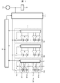
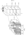
- FIG. 1 is a diagram showing an outline of a battery system.
- the battery system of the present invention includes a battery rack 1, and a plurality of battery sub-rack 2 is mounted inside the battery rack 1, and the battery sub-rack 2 has a plurality of battery modules M1 to Mn arranged in parallel.
- the battery module group N (Na) is stored.
- the plurality of battery modules M1 to Mn have a structure for cooling the battery modules by flowing outside air through the gap between the battery modules M1 to Mn and the battery rack 1 or the gap between the battery sub-rack 2. With such a configuration, each battery module can be uniformly cooled.
- the battery rack 1 includes the collective fan 3, and the battery subrack 2 includes the individual fan 7.
- the air flowing through the individual fan 7 supplies the outside air through the collective fan 3. It becomes the form which exhausts.
- both the collective fan 3 and the individual fan 7 may be any one that can pump air, and may be replaced with a pump, a blower, or the like.
- the individual fan 7 has a function of supplying and exhausting outside air from the front side of the battery rack 1 to the flow path space 14 provided in the rear portion of the battery rack 1.
- the collective fan 3 has a function of collectively exhausting the outside air exhausted into the flow path space 14.
- the collective fan 3 and the individual fan 7 do not have to be a single fan, but may have a configuration in which a plurality of fans are juxtaposed. Each fan is selected so that the air volume of the collective fan 3 is larger than the air volume of the individual fan 7. With such a configuration, when the individual fans 7 disposed in the battery sub-rack 2b and 2c other than the battery sub-rack 2a are stopped, it is possible to increase the amount of air flowing through the battery sub-rack 2a. .
- the rated air volume of the collective fan 3 may be about 3n times the rated air volume of the individual fan 7. .
- the battery subrack 2 is provided with a gas leak detection device 6 individually, and the gas leak detection device 6 detects gas generated when an abnormality occurs in the battery modules M1 to Mn.
- the generated gas may be hydrogen gas or a volatile gas of a carbonate-based solvent that is an electrolytic solution.
- FIGS. 2A and 2B are cross-sectional views of the battery subrack 2 showing details of the battery subrack 2.
- the gas leak detection device 6 is preferably mounted at a position that is always downstream of the cooling air as compared with the battery module group N.
- the individual fan 7 may be disposed either outside the battery subrack 2 as shown in FIG. 2A or inside the battery subrack 2 as shown in FIG.
- the gas leak detection device 6 can increase the detection sensitivity by selectively arranging the upper side or the lower side in the vertical direction according to the gas component to be detected. For example, when it is desired to detect a light gas such as hydrogen gas, the gas leak detection device 6 is disposed on the upper part of the battery subrack 2, and conversely, when it is desired to detect a gas heavier than the specific gravity of air, the gas leak detection device. It is conceivable to arrange 6 under the battery subrack 2.
- FIG. 3 shows signal connections inside the battery rack 1.
- the control device 8 provided in the battery rack 1 acquires the gas detection signals 6s of all the gas leak detection devices 6 (6a to 6c) inside the battery rack 1 via the gas detection signal communication wiring 106, and each battery support. Monitor the battery module in Black 2 for gas leaks. Further, the control device 8 outputs an individual fan operation signal 7s for controlling the driving and stopping of the individual fans 7 (7a to 7c) in the battery rack 1 via the individual fan operation signal wiring 107. Further, the control device 8 is also connected to the collective fan 3 through the collective fan operation signal communication wiring 103, and outputs an collective fan operation signal 3 s for controlling the drive and stop of the collective fan 3.
- control device 8 performs information communication with the battery modules M1 to Mn constituting the battery module group N (Na to Nc) via the communication wiring 108, and the battery which is various parameters inside each of the battery modules M1 to Mn. An information signal 8s is acquired.
- FIG. 4 is a diagram showing a signal processing flow inside the control device 8.
- the battery information signal 8s of each of the battery modules M1 to Mn is input to the battery temperature control calculation unit 110 via the communication wiring 108.
- the battery temperature control calculation unit 110 uses the temperature information, various voltage information, and current information inside each battery module, which is the battery information signal 8s, so that the temperature of the battery cell inside the battery module is irreversibly damaged.
- the collective fan operation command Ta and the individual fan operation commands Tm are calculated. For example, when the temperature rises with respect to the battery modules belonging to each battery subrack 2, the individual fan operation command Tm is changed to operate the individual fan 7 corresponding to each battery subrack 2.
- the collective fan operation command Ta may be changed when the average of the temperature information of all the battery modules exceeds a predetermined threshold value. Thereafter, the calculated collective fan operation command Ta is output from the battery temperature control calculation unit 110 to the collective fan control calculation unit 112, and the calculated individual fan operation command Tm is output to the individual fan control calculation unit 113.
- the gas leak detection determination unit 111 monitors the gas detection signal 6s from the gas leak detection device 6 (6a to 6c) installed in each battery sub-rack 2, and at least one gas detection signal 6s is a gas.
- the leakage detection signal Fg is changed and output to the collective fan control calculation unit 112.
- the gas leakage detection determination unit 111 detects a gas leakage
- the leakage subrack information Gm determined after determining from which battery subrack 2 the gas detection signal 6s is detected is output to the individual fan control calculation unit. To do.
- the collective fan control command unit 112 receives the collective fan operation command Ta and the gas leak detection signal Fg. As shown in the table of FIG. 5A, in the collective fan control calculation unit 112, the leak detection signal Fg indicates that no leak is detected, and the collective fan operation command Ta instructs the stop of the collective fan 3. If so, an operation command 3S for stopping the fan is output (condition (4)). Under other conditions (condition (1) to condition (3)), the collective fan operation command 3s is output so that the collective fan 3 is in a driving state. By adopting such control, when there is no gas leakage and the cooling of the battery module is not greatly required, the collective fan 3 that consumes more power than the individual fan 7 can be stopped to operate the battery system. Therefore, the battery system as a whole can perform highly safe control while reducing power consumption.
- the individual fan control calculation unit 113 includes individual fan operation commands Tm (Tm X (X is 1 to p)) and leakage subrack information Gm (for each of the p individual fans 7 mounted on the battery rack 1.
- Gm Y (Y is the number of subrack)) is input.
- the number of battery subrack is two for simplicity of explanation, but the number of battery subrack is not particularly limited.
- the following disclosure subrack information Gm in this embodiment, battery subrack 2a, in correspondence with 2b and Gm a, Gm b.
- condition (6), condition (7), condition (10), Or the condition (11) gas leakage is detected in either the battery subrack 2a or 2b (condition (6), condition (7), condition (10), Or the condition (11)) will be described.
- condition (7), condition (10), or condition (11) in the table of FIG. In this case, even if the individual fan operation command Tm X is either a drive instruction or a stop instruction, the individual fan 7 installed in the battery subrack 2 having a gas leak is driven. And the individual fan 7 installed in the battery subrack 2 without gas leakage is stopped.
- the collective fan 3 is surely driven in the gas leak state, and the collective fan 3 is larger than the rated air volume of each individual fan, so that the individual fan installed in the battery subrack 2 without gas leak. By stopping 7, it becomes possible to send a large air volume to the battery subrack 2 that has temporarily leaked gas.
- FIG. 6 shows a control processing flowchart in the control device 8 at the time of detecting the gas leak described above.
- the gas detection signal 6s is input to the control device 8 (step S11).
- the gas leakage detection determination unit 111 determines whether or not gas is leaking based on the information of the gas detection signal 6s (step S12). If no gas leak is detected here, the control flow of the collective fan 3 and the individual fan 7 proceeds to step S16 and step S19, respectively.
- Step S16 is a process in the collective fan control calculation unit 112, and it is determined whether the collective fan operation command Ta output from the battery temperature control calculation unit 110 is a drive instruction. Then, the collective fan 3 is driven, and if it is a stop instruction, the process proceeds to step S18 and the collective fan 3 is stopped.
- Step S19 is a process in the individual fan control calculation unit 113, and it is determined whether or not the individual fan operation command Tm output from the battery temperature control calculation unit 110 is a drive instruction. Then, the individual fan 7 is driven, and if it is a stop instruction, the process proceeds to step S21 and the individual fan is stopped.
- step 12 the process proceeds to step S13, and the gas leak detection determination unit 111 identifies the battery subrack 2 in which the gas leak has occurred. Thereafter, the process proceeds to step S14, and the collective fan operation signal 3s for driving the collective fan 3 is output from the collective fan control calculation unit 112. Finally, the process proceeds to step S15, where the individual fan operation signal 7s for driving the individual fan 7 installed in the battery subrack 2 that has leaked gas is output from the individual fan control calculation unit 113, and further, the battery fan that has not leaked gas. An individual fan operation signal 7s for stopping the individual fan 7 installed in the black 2 is output.
- the individual fan 7 of the battery sub-rack in which no gas leak has occurred is stopped.
- the collective fan 3 can be brought into a driving state.
- the ratio of the air volume flowing into the battery sub-rack 2 in which gas leakage occurs in the air volume of the collective fan 3 can be increased, a small size in which the rated air volume of the individual fans 7 installed in the battery rack 1 is reduced. Therefore, it is possible to use a separate individual fan 7, which can contribute to downsizing.
- the enlargement of the individual fan 7 can also be suppressed, it is possible to reduce the drive power loss of the individual fan 7 and to realize a battery system that suppresses power consumption.
- (Second embodiment) 2 shows a second embodiment according to the present invention.
- the difference from the first embodiment is that each fan is controlled based on the abnormal voltage of the battery cells constituting the battery module.
- the same drawing numbers as those in the first embodiment are used for the parts that are not changed from the first embodiment.
- FIG. 7 is a view showing a battery system according to a second embodiment of the present invention.
- the battery racks 1A, 1B, and 1C are all the same, and their output terminals are connected in parallel, for example. Further, the battery rack is connected to the power converter 11 and is configured to be able to exchange power with the external power source 10 and the load 9 via the power converter 11.
- the power converter 11 is a DC / AC converter
- a commercial power system may be used for the external power source 10 and an AC load may be used for the load 9.
- control device 8 monitors the voltage across each battery module.
- a switch 12 is provided in a part of the series circuit of the battery modules, and the switch 12 can be opened and closed by an operation signal of the control device 8.
- the control device 8 is configured to receive the battery information signal 8S from the module control device 5 and to communicate information with the overall control device 4 provided outside the battery rack.
- the overall control device 4 can operate the power converter 11 based on the information obtained from the control device 8. Note that the control device 8 is provided inside the battery rack 1 although not shown.
- FIG. 8 shows a detailed view of the battery module M11.
- a plurality of unit battery cells 13 are connected in series inside the battery module, and the potentials at both ends of each unit battery cell 13 are connected to the module control device 5 and measured.
- the module control device 5 includes a cell voltage balance unit 5A, a cell control circuit 5B, a contact input / output unit 5C, an external communication terminal 5D, and the like.
- the cell control circuit 5B has functions such as a cell voltage measurement calculation unit 5B1 and a cell voltage balance control calculation unit 5B2.
- the cell voltage measurement calculation unit 5B1 calculates each battery cell voltage information, and cell voltage balance.
- the control calculation unit 5B2 identifies a battery cell having a high voltage according to the cell voltage information and drives the cell voltage balance unit 5A.
- the cell voltage balance unit 5A has a configuration in which, for example, a circuit in which a resistor 5A1 and a switch device 5A2 are connected in series is connected in parallel to both ends of each cell.
- the cell control circuit 5B drives the contact input / output unit 5C when detecting an abnormal decrease or an abnormal increase in battery cell voltage information.
- the abnormal rise mentioned here is, for example, when a voltage of 120% or more of the nominal voltage is generated, and the abnormal drop is, for example, a case where the voltage is 0.5 V or less.
- the gas leak detection device 6 leaks by transmitting the abnormal voltage signal 5S from the contact input / output unit 5C or the external communication terminal 5D to the control device 8. Since it is possible to switch the individual fan and the collective fan to the mode at the time of leakage detection earlier than the detection of gas, the effect of diluting the combustible gas can be increased more reliably.
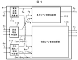
- an abnormal voltage determination unit 114 is provided inside the control device 8.
- the abnormal voltage flag VFg is output from the abnormal voltage determination unit 114 to the collective fan control calculation unit 112. Further, the abnormal voltage determination unit 114 determines which of the battery modules M11 to M1n has an abnormal voltage, and a signal for identifying the subrack having the battery module in which the abnormal voltage has occurred, that is, the abnormal voltage subrack. Information Vm (Vm Y (Y corresponds to the number of subrack)) is generated and output to the individual fan control calculation unit 113.
- the collective fan control command unit 112 receives the collective fan operation command Ta and the abnormal voltage flag VFg. As shown in the table of FIG. 10A, in this collective fan control calculation unit 112, only when the abnormal voltage flag VFg is not input and the collective fan operation command Ta instructs the collective fan 3 to stop. Then, an operation command 3S for stopping the fan is output (condition (16)). Under other conditions (condition (13) to condition (15)), the collective fan operation command 3s is output so that the collective fan 3 is in a driving state. By adopting such control, there is no gas leakage, but it becomes possible to immediately drive the collective fan 3 when a sign of gas leakage is seen, and the gas concentration in one space rapidly increases at the time of gas leakage. Can be prevented in advance.
- the number of battery subrack is two for simplicity of explanation, but the number of battery subrack is not particularly limited.
- the fan operation signal 7s x (X is 1 to p) is a stop instruction (condition (24)).
- the individual fan operation command Tm X is a drive instruction or a stop instruction and there is a battery module in which an abnormal voltage is generated in any battery subrack 2, it is output to each individual fan 7.
- the individual fan operation signal 7s x is a drive instruction (condition (17) or condition (21)).
- the collective fan 3 is surely driven in the abnormal voltage detection state, and the collective fan 3 is larger than the rated air volume of each individual fan. Therefore, the battery subrack without the battery module in which the abnormal voltage is generated is provided. By stopping the individual fan 7 installed in 2, it becomes possible to send a large air volume to the battery subrack 2 having the battery module in which abnormal voltage is temporarily generated.
- By performing the control of the present embodiment it is possible to switch the individual fan and the collective fan to the mode at the time of leak detection faster than the gas leak detection device 6 detects the leak, so that the dilution of the combustible gas can be performed more reliably. The effect can be enhanced.
- the battery module often generates heat. By using this control method, it is possible to enhance cooling of the battery module in which the abnormal voltage has occurred. It is also possible to prevent leakage.
- FIG. 11 shows a third embodiment according to the present invention.
- the individual fan 7 is a fan 70 (70a) capable of pumping air in the forward direction (forward rotation direction) and the reverse direction (reverse rotation direction).
- the individual fan 70a By changing the air flow direction by the individual fan 70a, the effect of diluting the combustible gas can be enhanced.
- the direction in which air flows from the battery subrack 2 to the flow path space 14 is defined as the forward rotation direction
- the direction in which air flows from the flow path space 14 to the battery subrack 2 is defined as the reverse rotation direction.
- the specific control block is the same as in FIG.
- FIG. 12 shows the processing contents of the individual fan control calculation unit 113.
- the number of battery subrack is two for simplicity of explanation, but the number of battery subrack is not particularly limited.
- the individual fan operation signal output to each individual fan 70 70s x (X is 1 to p) is a stop instruction (condition (32)).
- the individual fan operation command Tm X is a drive instruction or a stop instruction and gas leakage is detected in any battery subrack 2
- the individual fan operation output to each individual fan 70 is detected.
- the signal 70s x is a forward rotation instruction (condition (25) or condition (29)).
- operation signal 70s x is a positive rotation instruction (condition (28)).
- the power consumption becomes larger than that of the first embodiment, but the battery subrack 2 having a gas leak has a larger air volume than the first embodiment. Can send. Therefore, the gas concentration can be reduced more instantaneously.
- the present invention as described above, it is possible to provide a battery system that can reliably and quickly reduce the gas concentration when a gas leak occurs.
Landscapes
- Engineering & Computer Science (AREA)
- Manufacturing & Machinery (AREA)
- Chemical & Material Sciences (AREA)
- Chemical Kinetics & Catalysis (AREA)
- Electrochemistry (AREA)
- General Chemical & Material Sciences (AREA)
- Secondary Cells (AREA)
Description
本発明は、単電池を複数個直並列接続した電池システムに関するものである。
従来の電池システムでは、例えば、電池を異常な状態で充放電した場合に電池内部でガスが発生して内圧が上昇し破裂に至るため、破裂を防止するための安全弁をセルに設けて電池の内容物をセルの外部に排出する。このような場合、リチウムイオン電池は安全弁から可燃性ガスが排出されるため、速やかに外気との混合により可燃性ガスの爆発限界以下まで希釈することでシステム全体としてより一層の安全を保つことができる。ここで可燃性ガスを希釈するには、排気ファンは十分な風量を流すことが要求される。特許文献1に係る電池システムでは、可燃性ガス検知器に排気ファンを連動することでガスを排出する機構が示されている。
ところで、電池システムの大型化につれて、装置を構成する個々の単電池セルの総数は膨大なものとなる。装置内の電池セルの実装密度を高める場合、電池セルの損失が発熱源となるため冷却風を外部から通流しながら放熱を行う方式が行われる(特許文献2)。
ここで放熱のための冷却風はファン等で駆動する方式が一般的であるので、冷却風によって可燃性ガスを排出する構成が考えられる。
しかし、このような電池システムで可燃性ガス検知器の信号と冷却ファンを連動させようとすると、冷却に必要な風量よりも可燃性ガスの排出に必要な風量が大きいため、ファンの定格風量を大きく設計しなくてはならず、電池システムの大型化を招いていた。
本発明は、上記実情に鑑みてなされたものであり、電池システムの大型化を抑えながら、可燃性ガスの排出を促進できるようにした電池システムを提供することを目的としている。
上記目的を達成するために、本発明の実施形態に係る電池システムは、電池モジュールを複数収納する電池サブラックを複数備えた電池ラックを有する電池システムで、前記電池サブラックは第一ファン及びガス検出装置を有し、前記電池ラックは、複数の前記電池サブラックの第一ファンから排気された空気を排気する第二ファンを有し、前記第二ファンは、定格風量が前記第一ファンの定格風量よりも大きくなるように構成され、一の前記電池サブラックにおける前記ガス検出装置によって所定のガスが検知された場合、当該一の電池サブラックにおける第一ファンを駆動させ、さらに当該一の電池サブラック以外の電池サブラックにおける第一ファンを停止させた状態で前記第二ファンを駆動させることを特徴とする。
本発明を用いることによって、大型化を抑えつつ、可燃性ガスの排出の促進を可能とした電池システムを提供することができる。
以下、本発明の実施形態に係る電池システムについて、図面を参照して詳細に説明する。
(第1実施例)
はじめに、本発明の実施形態に係る電池システムについて、図1を参照して説明する。図1は、電池システムの概要を示す図である。本発明の電池システムは、電池ラック1を備え、電池ラック1の内部には複数段の電池サブラック2が搭載されており、当該電池サブラック2は、電池モジュールM1~Mnが複数個並置された電池モジュール群N(Na)を収納する構成となっている。複数の電池モジュールM1~Mnは、当該電池モジュールM1~Mnと電池ラック1との間隙、または電池サブラック2の間隙に外気を通流することで電池モジュールの冷却を図る構造となっている。このような構成にすることによって、各電池モジュールを均一に冷やすことができる。また、外気を通流する手段として、電池ラック1には集合ファン3を、電池サブラック2には個別ファン7を備えており、個別ファン7を通流する空気は集合ファン3を通じて外気を給排気する形態となっている。ここで、集合ファン3、個別ファン7はいずれも空気を圧送できるものであればよく、ポンプ・ブロア等で置き換えても構わない。なお、個別ファン7は、電池ラック1の正面側から電池ラック1の後背部に設けられた流路空間14に外気を給排気する機能を有する。また、集合ファン3は、上記流路空間14に排気された外気をまとめて排気する機能を有している。後述する集合ファン3を用いた場合、このように構成することによって、例えば電池サブラック2a以外の電池サブラック2b及び2cに設置された個別ファン7を停止させた場合に、電池サブラック2aに通常よりも多くの風量を流すことが可能となる。
はじめに、本発明の実施形態に係る電池システムについて、図1を参照して説明する。図1は、電池システムの概要を示す図である。本発明の電池システムは、電池ラック1を備え、電池ラック1の内部には複数段の電池サブラック2が搭載されており、当該電池サブラック2は、電池モジュールM1~Mnが複数個並置された電池モジュール群N(Na)を収納する構成となっている。複数の電池モジュールM1~Mnは、当該電池モジュールM1~Mnと電池ラック1との間隙、または電池サブラック2の間隙に外気を通流することで電池モジュールの冷却を図る構造となっている。このような構成にすることによって、各電池モジュールを均一に冷やすことができる。また、外気を通流する手段として、電池ラック1には集合ファン3を、電池サブラック2には個別ファン7を備えており、個別ファン7を通流する空気は集合ファン3を通じて外気を給排気する形態となっている。ここで、集合ファン3、個別ファン7はいずれも空気を圧送できるものであればよく、ポンプ・ブロア等で置き換えても構わない。なお、個別ファン7は、電池ラック1の正面側から電池ラック1の後背部に設けられた流路空間14に外気を給排気する機能を有する。また、集合ファン3は、上記流路空間14に排気された外気をまとめて排気する機能を有している。後述する集合ファン3を用いた場合、このように構成することによって、例えば電池サブラック2a以外の電池サブラック2b及び2cに設置された個別ファン7を停止させた場合に、電池サブラック2aに通常よりも多くの風量を流すことが可能となる。
ここで、集合ファン3、個別ファン7は単一のファンでなくともよく、複数のファンを並置した構成でもよい。なお、集合ファン3の風量は個別ファン7の風量よりも大きくなるよう各ファンを選定する。このような構成とすることによって、電池サブラック2a以外の電池サブラック2b、2cに配置された個別ファン7を停止させた場合に、電池サブラック2aに流れる風量を増加させることが可能となる。
より具体的には、電池ラック1に搭載された電池サブラック2が3n個存在する場合には、集合ファン3の定格風量は個別ファン7の定格風量の3n倍程度とすることなどが考えられる。
また、電池サブラック2には個別にガス漏えい検知装置6が備えられており、電池モジュールM1~Mnに異常が発生した場合に発生するガスを当該ガス漏えい検知装置6によって検出している。なお、本実施形態においては電池セルはリチウムイオン電池を想定しているため、発生するガスについては水素ガスや電解液であるカーボネート系溶媒の揮発ガスなどが考えられる。
図2(a)および図2(b)は、電池サブラック2の詳細を示す電池サブラック2の断面図である。図のとおり、ガス漏えい検知装置6は電池モジュール群Nに比べ、常に冷却風の下流側になる位置に搭載されるとよい。なお、ガス漏えい検知装置6の位置は、図2(a)に示すように電池サブラック2の内側に配置されても、図2(b)に示すように電池サブラック2の外側に配置されても構わない。また、個別ファン7についても、図2(a)に示すような電池サブラック2の外側、又は図2(b)に示すような電池サブラック2の内側のいずれに配置されていてもよい。
さらに、ガス漏えい検知装置6は、検出するガスの成分に応じて鉛直方向の上側か下側かを選択的に配置することで検知感度を高めることができる。例えば、水素ガスのように軽い気体を検出したい場合にはガス漏えい検知装置6を電池サブラック2の上部に配置し、逆に空気の比重よりも重いガスを検出したい場合にはガス漏えい検知装置6を電池サブラック2の下部に配置することなどが考えられる。
図3は、電池ラック1内部の信号接続を示している。電池ラック1に備えられた制御装置8は、ガス検知信号通信配線106を介して電池ラック1内部の全てのガス漏えい検知装置6(6a~6c)のガス検知信号6sを取得し、各電池サブラック2内の電池モジュールにガス漏れが無いか監視する。また制御装置8は、個別ファン操作信号配線107を介して、電池ラック1内部の個別ファン7(7a~7c)の駆動および停止を制御する個別ファン操作信号7sを出力する。さらに制御装置8は、集合ファン操作信号通信配線103で集合ファン3とも接続され、集合ファン3の駆動および停止を制御する集合ファン操作信号3sを出力する。なお、個別ファン7(7a~7c)及び集合ファン3の制御方法の詳細については後述する。また、制御装置8は通信配線108を介して、電池モジュール群N(Na~Nc)を構成する電池モジュールM1~Mnと情報通信を行い、各電池モジュールM1~Mnの内部の諸パラメータである電池情報信号8sを取得する。
図4は、制御装置8内部における信号処理フローを示した図である。まず、各電池モジュールM1~Mnの電池情報信号8sが、通信配線108を介して電池温度制御演算部110に入力される。ここで電池温度制御演算部110は、電池情報信号8sである各電池モジュール内部の温度情報、各種電圧情報、電流情報を用いて、電池モジュール内部の電池セルが不可逆なダメージを受ける程度まで温度が上昇した場合に、集合ファン操作指令Taおよび各個別ファン操作指令Tmを演算する。例えば、各々の電池サブラック2に属する電池モジュールに関して温度が上昇した場合にはそれぞれの電池サブラック2に対応した個別ファン7を操作すべく個別ファン操作指令Tmを変化させる。また、全ての電池モジュールの温度情報の平均が所定の閾値を超えた場合に集合ファン操作指令Taを変化させてもよい。その後、演算された集合ファン操作指令Taは電池温度制御演算部110から集合ファン制御演算部112に出力され、演算された個別ファン操作指令Tmは個別ファン制御演算部113に出力される。
一方、ガス漏えい検知判定部111では、各々の電池サブラック2に設置されたガス漏えい検知装置6(6a~6c)からのガス検知信号6sを監視して、一つでもガス検知信号6sがガス漏えいを検知した場合には漏えい検知信号Fgを変化させて集合ファン制御演算部112に出力する。また、ガス漏えい検知判定部111はガス漏えいを検知した場合、ガス検知信号6sがいずれの電池サブラック2から検知されたかを判定した後に判定した漏えいサブラック情報Gmを個別ファン制御演算部に出力する。
集合ファン制御演算部112には、集合ファン操作指令Ta及びガス漏えい検知信号Fgが入力される。図5(a)の表に示すように、この集合ファン制御演算部112では漏えい検知信号Fgが漏えいを検知していない場合であってかつ集合ファン操作指令Taが集合ファン3の停止を指示している場合、ファン停止とする操作指令3Sが出力される(条件(4))。その他の条件(条件(1)~条件(3))では、集合ファン3が駆動状態となるように集合ファン操作指令3sを出力する。このような制御にすることによって、ガス漏えいが無く、電池モジュールの冷却が大きく要求されていない場合には、個別ファン7よりも消費電力の大きい集合ファン3を停止して電池システムを運転できる。そのため、電池システム全体として、消費電力を低減しつつも安全性の高い制御を行うことが可能となる。
一方、個別ファン制御演算部113には、電池ラック1に搭載されたp個の個別ファン7それぞれについての個別ファン操作指令Tm(TmX(Xは1~p))及び漏えいサブラック情報Gm(GmY(Yはサブラックの個数))が入力される。なお、本実施形態では説明を単純にするため電池サブラックの個数を2個とするが、特に電池サブラックの個数については限定されない。以下本実施形態では漏えいサブラック情報Gmは、電池サブラック2a、2bと対応させてGma、Gmbとする。
具体的な処理を図5(b)の表に示す。まず、個別ファン操作指令TmX(Xは1~p)が停止指示の場合で、どの電池サブラック2でもガスが漏えいしていない場合には、各個別ファン7に出力される個別ファン操作信号7sx(Xは1~p)は停止指示となる(条件(12))。一方、個別ファン操作指令TmXが駆動指示又は停止指示の場合であって、いずれの電池サブラック2でもガスの漏えいが検知されている場合には、各個別ファン7に出力される個別ファン操作信号7sxは駆動指示となる(条件(5)又は条件(9))。なお、個別ファン操作指令TmXが駆動指示であっていずれの電池サブラック2からもガスの漏えいが検知されていない通常の運転状態では、当然のことながら各個別ファン7に出力される個別ファン操作信号7sxは駆動指示となる(条件(8))。
続いて、図5(b)の表において、電池サブラック2a又は2bのいずれかの電池サブラックにおいてガスの漏えいが検知された場合(条件(6)、条件(7)、条件(10)、又は条件(11))について説明する。図5(b)の表の条件(6)、条件(7)、条件(10)、又は条件(11)に示すように、いずれかの電池サブラック2でガスの漏えいが検知されている場合には、個別ファン操作指令TmXが駆動指示又は停止指示のいずれかの場合であっても、ガス漏えいのあった電池サブラック2に設置されている個別ファン7を駆動させる。そして、ガス漏えいの無い電池サブラック2に設置されている個別ファン7については停止させる。上述したように、ガス漏えい状態では集合ファン3は確実に駆動しており、さらに集合ファン3は各個別ファンの定格風量よりも大きいため、ガス漏えいの無い電池サブラック2に設置された個別ファン7を停止することによって一時的にガス漏えいのあった電池サブラック2に大きな風量を送ることが可能となる。
続いて、上述したガス漏えい検知時の制御装置8での制御処理フローチャートを図6に示す。まず、ガス検知信号6sが制御装置8に入力される(ステップS11)。続いて、ガス漏えい検知判定部111にてガス検知信号6sの情報に基づいてガスが漏えいしているかどうか判断される(ステップS12)。ここでガス漏えいが検知されなかった場合、集合ファン3及び個別ファン7の制御フローはそれぞれステップS16及びステップS19に移行する。ステップS16は集合ファン制御演算部112での処理であり、電池温度制御演算部110から出力された集合ファン操作指令Taが駆動指示であるか否かを判断し、駆動指示である場合、ステップ17に進み集合ファン3を駆動し、停止指示である場合にはステップS18に進み集合ファン3を停止する。
ステップS19は個別ファン制御演算部113での処理であり、電池温度制御演算部110から出力された個別ファン操作指令Tmが駆動指示であるか否かを判断し、駆動指示である場合、ステップS20に進み個別ファン7を駆動し、停止指示である場合にはステップS21に進み個別ファンを停止する。
一方、ステップ12にてガス漏えいが検知された場合にはステップS13に進み、ガス漏えい検知判定部111にて、ガス漏えいが発生している電池サブラック2の特定をする。その後ステップS14に進み、集合ファン制御演算部112から集合ファン3を駆動させる集合ファン操作信号3sを出力する。最後にステップS15に進み、個別ファン制御演算部113からガス漏えいしている電池サブラック2に設置された個別ファン7を駆動させる個別ファン操作信号7sが出力され、さらにガス漏えいしていない電池サブラック2に設置された個別ファン7を停止させる個別ファン操作信号7sが出力される。
上述したように、本実施形態のような構成にすれば、いずれかの電池サブラック2内部でガス漏えいが発生した場合、ガス漏えいが発生していない電池サブラックの個別ファン7を停止するとともに、集合ファン3を駆動状態にすることができる。この結果、集合ファン3の風量のうちガス漏えいが発生する電池サブラック2へ流入する風量の割合を増すことができるため、電池ラック1内に設置される個別ファン7の定格風量を低減した小型な個別ファン7を用いることが可能となり、小型化に寄与することができる。また、個別ファン7の大型化も抑制できるので、個別ファン7の駆動電源損失も低減することが可能となり、電力消費量を抑制した電池システムを実現できる。また上述しなかったが、3つ以上の電池サブラックを有する電池システムにおいては、ガス漏えいが検知されなかった電池サブラックのうち少なくとも1つの電池サブラックにおける個別ファンを停止させれば上記効果は実現できる。このように制御する場合の例としては、温度の高い電池モジュールを有する電池サブラックの個別ファンを優先的に駆動させて、ガス漏えいが無い他の電池サブラックの個別ファンを停止する制御がある。このように制御することによって、温度の高い電池モジュールの劣化を防止しつつも、ガスの濃度が高くなるのを防止することができる。
(第2実施例)
本発明に関わる第2の実施例を示している。第1の実施例と異なる点は、電池モジュールを構成する電池セルの異常電圧に基づいて各ファンの制御を行う点である。なお、図面番号については、第1の実施例から変化が無い部分については第1の実施例と同様の図面番号を用いている。
本発明に関わる第2の実施例を示している。第1の実施例と異なる点は、電池モジュールを構成する電池セルの異常電圧に基づいて各ファンの制御を行う点である。なお、図面番号については、第1の実施例から変化が無い部分については第1の実施例と同様の図面番号を用いている。
図7は、本発明に関わる第2の実施例の電池システムを示す図である。電池ラック1A、1B、1Cは全て同じものであって、その出力端子は例えば並列接続されている。さらに電池ラックは電力変換器11に接続されており、電力変換器11を介して外部電源10や負荷9との間で電力を授受できる構成となっている。ここで例えば電力変換器11が直流/交流変換器であった場合には、外部電源10には商用電力系統、負荷9には交流負荷を用いてもよい。
電池ラック1の内部では電池モジュールM11~M1nが直列接続されており、制御装置8は各電池モジュールの両端電圧を監視している。また電池モジュールの直列回路の一部にはスイッチ12が備えられており、スイッチ12は制御装置8の操作信号により開閉が可能である。また制御装置8は、モジュール制御装置5から電池情報信号8Sを受信して、電池ラック外部に備えられた統括制御装置4と情報通信可能なように構成されている。統括制御装置4は制御装置8から得た情報をもとに電力変換器11を操作可能である。なお、当該制御装置8については図示しないが、電池ラック1の内部に設けられている。
図8は、電池モジュールM11の詳細図を示している。電池モジュール内部には複数の単位電池セル13が直列接続されており、各単位電池セル13の両端電位はモジュール制御装置5に接続され、測定されている。モジュール制御装置5の内部はセル電圧バランス部5A、セル制御回路5B、接点入出力部5C、外部通信端子5Dなどが備えられている。ここで、セル制御回路5Bはセル電圧計測演算部5B1、およびセル電圧バランス制御演算部5B2などの機能を備えており、セル電圧計測演算部5B1が各電池セル電圧情報を演算し、セル電圧バランス制御演算部5B2はセル電圧情報に従って電圧が高い電池セルを特定してセル電圧バランス部5Aを駆動する。なお、セル電圧バランス部5Aは、例えば抵抗5A1とスイッチ装置5A2を直列した回路を各セル両端に並列接続する構成となっている。
ここで、セル制御回路5Bは電池セル電圧情報の異常低下または異常上昇を検出した場合に接点入出力部5Cを駆動させる。なお、ここで言う異常上昇とは、例えば公称電圧の120%以上の電圧が発生した場合、異常低下とは例えば電圧が0.5V以下になった場合である。可燃性ガスの漏えいが発生する際は電池セルが異常な状態で充放電されているため、電池セル電圧を常時監視すれば未然にガス漏えいを予測することができる。したがって、このような異常電圧をセル制御回路5Bで検出した場合、当該接点入出力部5Cまたは外部通信端子5Dから異常電圧信号5Sを制御装置8に送信することで、ガス漏えい検知装置6が漏えいを検知するよりも早く、個別ファン、集合ファンを漏えい検出時のモードに切り替えることができるため、より確実に可燃性ガスの希釈効果を高めることができる。
具体的な制御ブロックの内容については、図9を用いて説明する。具体的に第1の実施例と異なる点は、制御装置8の内部に異常電圧判定部114を有する点である。この異常電圧判定部114に上述した異常電圧信号5Sが入力された場合、当該異常電圧判定部114から集合ファン制御演算部112に異常電圧フラグVFgが出力される。さらに当該異常電圧判定部114では、電池モジュールM11~M1nのいずれのモジュールで異常電圧が発生したのかを判定し、異常電圧が発生した電池モジュールを有するサブラックを特定する信号、すなわち異常電圧サブラック情報Vm(VmY(Yはサブラックの個数に対応))を生成し、個別ファン制御演算部113に出力する。
集合ファン制御演算部112には、集合ファン操作指令Ta及び異常電圧フラグVFgが入力される。図10(a)の表に示すように、この集合ファン制御演算部112では異常電圧フラグVFgが入力されない場合であってかつ集合ファン操作指令Taが集合ファン3の停止を指示している場合のみ、ファン停止とする操作指令3Sが出力される(条件(16))。その他の条件(条件(13)~条件(15))では、集合ファン3が駆動状態となるように集合ファン操作指令3sを出力する。このような制御にすることによって、ガス漏えいは無いが、ガス漏えいの前兆が見られたときに即座に集合ファン3を駆動することが可能となり、ガス漏えい時に一空間のガス濃度が急上昇することを、未然に防ぐことが可能となる。
続いて、個別ファン制御演算部113での処理について説明する。なお、本実施形態では説明を単純にするため電池サブラックの個数を2個とするが、特に電池サブラックの個数については限定されない。以下本実施形態では異常電圧サブラック情報Vmは、電池サブラック2a、2bと対応させてVma、Vmbとする。
具体的な処理を図10(b)の表に示す。まず、個別ファン操作指令TmX(Xは1~p)が停止指示の場合で、どの電池サブラック2でも異常電圧が発生した電池モジュールがない場合には、各個別ファン7に出力される個別ファン操作信号7sx(Xは1~p)は停止指示となる(条件(24))。一方、個別ファン操作指令TmXが駆動指示又は停止指示の場合であって、いずれの電池サブラック2でも異常電圧が発生している電池モジュールがある場合には、各個別ファン7に出力される個別ファン操作信号7sxは駆動指示となる(条件(17)又は条件(21))。なお、個別ファン操作指令TmXが駆動指示であっていずれの電池サブラック2からも異常電圧が発生している電池モジュールがない通常の運転状態では、当然のことながら各個別ファン7に出力される個別ファン操作信号7sxは駆動指示となる(条件(20))。
続いて、図10(b)の表において、電池サブラック2a又は2bのいずれかの電池サブラックにおいてガスの漏えいが検知された場合(条件(18)、条件(19)、条件(22)、又は条件(23))について説明する。図10(b)の表の条件(18)、条件(19)、条件(22)、又は条件(23)に示すように、いずれかの電池サブラック2で異常電圧が発生した電池モジュールが検知された場合には、個別ファン操作指令TmXが駆動指示又は停止指示のいずれかの場合であっても、異常電圧の発生した電池モジュールが配置されている電池サブラック2の個別ファン7を駆動させる。そして、異常電圧が発生した電池モジュールの無い電池サブラック2に設置されている個別ファン7を停止させる。上述したように、異常電圧の検出状態では集合ファン3は確実に駆動しており、さらに集合ファン3は各個別ファンの定格風量よりも大きいため、異常電圧が発生した電池モジュールの無い電池サブラック2に設置された個別ファン7を停止することによって一時的に異常電圧が発生した電池モジュールを有する電池サブラック2に大きな風量を送ることが可能となる。本実施例の制御をすることによって、ガス漏えい検知装置6が漏えいを検知するよりも早く、個別ファン、集合ファンを漏えい検出時のモードに切り替えることができるため、より確実に可燃性ガスの希釈効果を高めることができる。また、異常電圧が発生している場合には電池モジュールが発熱していることが多いため、当該制御方法を用いることによって、異常電圧が発生した電池モジュールの冷却を強化することも可能となり、ガスの漏えいを未然に防ぐことも可能となる。
なお、本実施例では特にガス漏えいがあった場合については言及していなかったが、異常電圧が発生していなくともガス漏えいが検知された場合には、当然第1の実施例にしたがって制御をするのは言うまでも無い。
(第3実施例)
図11は、本発明に関わる第3の実施例を示している。第1の実施例と異なる点は、個別ファン7を順方向(正回転方向)と逆方向(逆回転方向)に空気を圧送できるファン70(70a)とした点である。この個別ファン70aによって、空気の流れる方向を変化させることで、可燃性ガスの希釈効果を高めることができる。なお、ここでは電池サブラック2から流路空間14に空気を流す方向を正回転方向、流路空間14から電池サブラック2に空気を流す方向を逆回転方向とする。また、具体的な制御ブロックについては図4と同様である。
図11は、本発明に関わる第3の実施例を示している。第1の実施例と異なる点は、個別ファン7を順方向(正回転方向)と逆方向(逆回転方向)に空気を圧送できるファン70(70a)とした点である。この個別ファン70aによって、空気の流れる方向を変化させることで、可燃性ガスの希釈効果を高めることができる。なお、ここでは電池サブラック2から流路空間14に空気を流す方向を正回転方向、流路空間14から電池サブラック2に空気を流す方向を逆回転方向とする。また、具体的な制御ブロックについては図4と同様である。
図12に個別ファン制御演算部113の処理内容を示す。なお、本実施形態では説明を単純にするため電池サブラックの個数を2個とするが、特に電池サブラックの個数については限定されない。以下本実施形態では異常電圧サブラック情報Gmは、電池サブラック2a、2bと対応させてGma、Gmbとする。
まず、個別ファン操作指令TmX(Xは1~p)が停止指示の場合で、どの電池サブラック2でもガスが漏えいしていない場合には、各個別ファン70に出力される個別ファン操作信号70sx(Xは1~p)は停止指示となる(条件(32))。一方、個別ファン操作指令TmXが駆動指示又は停止指示の場合であって、いずれの電池サブラック2でもガスの漏えいが検知されている場合には、各個別ファン70に出力される個別ファン操作信号70sxは正回転指示となる(条件(25)又は条件(29))。なお、個別ファン操作指令TmXが駆動指示であっていずれの電池サブラック2からもガスの漏えいが検知されていない通常の運転状態では、当然のことながら各個別ファン70に出力される個別ファン操作信号70sxは正回転指示となる(条件(28))。
続いて、図12の表において、電池サブラック2a又は2bのいずれかの電池サブラックにおいてガスの漏えいが検知された場合(条件(26)、条件(27)、条件(30)、又は条件(31))について説明する。図12の表の条件(26)、条件(27)、条件(30)、又は条件(31)に示すように、いずれかの電池サブラック2でガスの漏えいが検知されている場合には、個別ファン操作指令TmXが駆動指示又は停止指示のいずれかの場合であっても、ガス漏えいのあった電池サブラック2に設置されている個別ファン7を正回転させる。そして、ガス漏えいの無い電池サブラック2に設置されている個別ファン7については逆回転させる。また、第1の実施例と同様に、ガス漏えい状態では集合ファン3は確実に駆動しており、さらに集合ファン3は各個別ファンの定格風量よりも大きい。
上述したように本実施例の制御方法を用いることによって、第1の実施例と比較して消費電力は大きくなるが、ガス漏えいのあった電池サブラック2に第1の実施例よりも大きな風量を送ることができる。そのため、より瞬間的にガスの濃度を低下させることが可能となる。以上、上述したように本発明を用いることによって、ガス漏えいが発生した場合に、確実に、そしてより早くガスの濃度を低下させることができる電池システムを提供することが可能となる。
1,1A,1B,1C 電池ラック
2,2a,2b,2c 電池サブラック
3 集合ファン
6,6a,6b,6c ガス漏えい検知装置
7,7a,7b,7c 個別ファン
M1~Mn,M11~M1n 電池モジュール
N,Na,Nb,Nc 電池モジュール群
2,2a,2b,2c 電池サブラック
3 集合ファン
6,6a,6b,6c ガス漏えい検知装置
7,7a,7b,7c 個別ファン
M1~Mn,M11~M1n 電池モジュール
N,Na,Nb,Nc 電池モジュール群
Claims (7)
- 電池モジュールを複数収納する電池サブラックを複数備えた電池ラックを有する電池システムにおいて、
前記電池サブラックは第一ファン及びガス検出装置を有し、
前記電池ラックは、複数の前記電池サブラックの第一ファンから排気された空気を排気する第二ファンを有し、
前記第二ファンは、定格風量が前記第一ファンの定格風量よりも大きくなるように構成され、
一の前記電池サブラックにおける前記ガス検出装置によって所定のガスが検知された場合、当該一の電池サブラックにおける第一ファンを駆動させ、さらに当該一の電池サブラック以外の電池サブラックにおける第一ファンを停止させた状態で前記第二ファンを駆動させることを特徴とする電池システム。 - 電池モジュールを複数収納する電池サブラックを複数備えた電池ラックを有する電池システムにおいて、
前記電池サブラックは第一ファン及びガス検出装置を有し、
前記電池ラックは、複数の前記電池サブラックの第一ファンから排気された空気を排気する第二ファンを有し、
前記第二ファンは、定格風量が前記第一ファンの定格風量よりも大きくなるように構成され、
一の前記電池サブラックにおける前記ガス検出装置によって所定のガスが検知された場合、当該一の電池サブラックにおける第一ファンを駆動させ、さらに当該一の電池サブラック以外のいずれかの電池サブラックにおける第一ファンを停止させた状態で前記第二ファンを駆動させることを特徴とする電池システム。 - 電池モジュールを複数収納する電池サブラックを複数備えた電池ラックを有する電池システムにおいて、
前記電池サブラックは第一ファンを有し、
前記電池モジュールは、当該電池モジュールを構成する電池セルの電圧情報を収集するセル制御回路を有し、
前記電池ラックは、複数の前記電池サブラックの第一ファンから排気された空気を排気する第二ファンを有し、
前記第二ファンは、定格風量が前記第一ファンの定格風量よりも大きくなるように構成され、
一の前記電池モジュールにおける電池セルの電圧が異常電圧となった場合、
前記異常電圧が検知された電池モジュールを有する電池サブラックの第一ファンを駆動させ、さらに異常電圧が検知されなかった電池モジュールを有する電池サブラックにおける第一ファンを停止させた状態で前記第二ファンを駆動させることを特徴とする電池システム。 - 請求項1乃至3のいずれかに記載の電池システムにおいて、
前記第二ファンの定格風量は、第一ファンの定格風量に前記電池サブラックの個数を乗じた値となることを特徴とする電池システム。 - 請求項1乃至4のいずれかに記載の電池システムにおいて、
前記第一ファンから排気された空気は、前記第二ファンまで連通された空間に排出されることを特徴とする電池システム。 - 請求項1乃至5のいずれかに記載の電池システムにおいて、
前記電池サブラックに収納された複数の電池モジュールは、それぞれ空間を介して配置されることを特徴とする電池システム。 - 請求項1乃至6のいずれかに記載の電池システムにおいて、
前記第一ファンは、逆回転可能となるように構成されていることを特徴とする電池システム。
Priority Applications (2)
| Application Number | Priority Date | Filing Date | Title |
|---|---|---|---|
| EP12821223.0A EP2797158A1 (en) | 2012-02-08 | 2012-02-08 | Cell system |
| PCT/JP2012/000814 WO2013118166A1 (ja) | 2012-02-08 | 2012-02-08 | 電池システム |
Applications Claiming Priority (1)
| Application Number | Priority Date | Filing Date | Title |
|---|---|---|---|
| PCT/JP2012/000814 WO2013118166A1 (ja) | 2012-02-08 | 2012-02-08 | 電池システム |
Publications (1)
| Publication Number | Publication Date |
|---|---|
| WO2013118166A1 true WO2013118166A1 (ja) | 2013-08-15 |
Family
ID=48946989
Family Applications (1)
| Application Number | Title | Priority Date | Filing Date |
|---|---|---|---|
| PCT/JP2012/000814 Ceased WO2013118166A1 (ja) | 2012-02-08 | 2012-02-08 | 電池システム |
Country Status (2)
| Country | Link |
|---|---|
| EP (1) | EP2797158A1 (ja) |
| WO (1) | WO2013118166A1 (ja) |
Cited By (7)
| Publication number | Priority date | Publication date | Assignee | Title |
|---|---|---|---|---|
| JP2013196908A (ja) * | 2012-03-19 | 2013-09-30 | Toshiba Corp | 電池ユニット盤 |
| WO2015029865A1 (ja) * | 2013-08-26 | 2015-03-05 | 日本碍子株式会社 | 二次電池ユニット及び二次電池設備 |
| WO2015190302A1 (ja) * | 2014-06-10 | 2015-12-17 | 新神戸電機株式会社 | 電池盤 |
| KR20170103242A (ko) * | 2016-03-03 | 2017-09-13 | 주식회사 엘지화학 | 벤팅 가스의 배기 구조가 개선된 셀 모듈 어셈블리 |
| CN112272881A (zh) * | 2019-02-11 | 2021-01-26 | 株式会社Lg化学 | 具有能够将冷却剂供给到电池模块中的结构的能量存储系统 |
| US11588204B2 (en) | 2020-07-14 | 2023-02-21 | Lg Energy Solution, Ltd. | Venting device and battery pack assembly including same, and vehicle including the battery pack assembly |
| JP2024511495A (ja) * | 2021-12-21 | 2024-03-13 | エルジー エナジー ソリューション リミテッド | バッテリーシステム、並びに当該バッテリーシステムを含むエネルギー貯蔵システム及び自動車 |
Families Citing this family (8)
| Publication number | Priority date | Publication date | Assignee | Title |
|---|---|---|---|---|
| JP6507951B2 (ja) * | 2015-09-07 | 2019-05-08 | 株式会社デンソー | 電池パック |
| DE102017207691B4 (de) * | 2017-05-08 | 2026-03-12 | Fritz GmbH & Co. KG | Stationäres Lagersystem für Batterien |
| US11848425B2 (en) * | 2017-10-12 | 2023-12-19 | General Electric Company | Temperature control for energy storage system |
| PL3579326T3 (pl) * | 2018-06-06 | 2024-02-12 | Samsung Sdi Co., Ltd. | Wykrywanie nieprawidłowych stanów układu baterii |
| US11569553B2 (en) | 2018-06-06 | 2023-01-31 | Samsung Sdi Co., Ltd. | Battery system configured to detect abnormal battery system conditions and method of the same |
| KR102826209B1 (ko) | 2019-09-27 | 2025-06-26 | 주식회사 엘지에너지솔루션 | 베이스 절연 부재가 구비된 배터리 모듈 |
| US12002985B2 (en) * | 2020-08-11 | 2024-06-04 | Vertiv Corporation | Battery cabinet with flame protection/management construction |
| EP4083580A1 (de) | 2021-04-30 | 2022-11-02 | Heraeus Nexensos GmbH | Sensoreinheit zur detektion von gasströmen in einem batterieblock oder in einer batterieeinheit, batterieblock, batterieeinheit und verfahren zur detektion von gasströmen in einem batterieblock oder in einer batterieeinheit |
Citations (5)
| Publication number | Priority date | Publication date | Assignee | Title |
|---|---|---|---|---|
| JPH1186891A (ja) | 1997-09-10 | 1999-03-30 | Toshiba Corp | パッケージ型燃料電池発電設備及びその運転制御方法 |
| JP2001297578A (ja) * | 2000-04-17 | 2001-10-26 | Visual Technology Kk | 情報処理システムおよび収容装置 |
| JP2003309935A (ja) * | 2002-04-16 | 2003-10-31 | Hitachi Ltd | 直流バックアップ電源装置 |
| JP2005243580A (ja) | 2004-02-27 | 2005-09-08 | Mitsubishi Heavy Ind Ltd | 電力貯蔵システム |
| JP2006079751A (ja) * | 2004-09-10 | 2006-03-23 | Hitachi Computer Peripherals Co Ltd | 情報処理装置及び直流バックアップ電源装置 |
-
2012
- 2012-02-08 WO PCT/JP2012/000814 patent/WO2013118166A1/ja not_active Ceased
- 2012-02-08 EP EP12821223.0A patent/EP2797158A1/en not_active Withdrawn
Patent Citations (5)
| Publication number | Priority date | Publication date | Assignee | Title |
|---|---|---|---|---|
| JPH1186891A (ja) | 1997-09-10 | 1999-03-30 | Toshiba Corp | パッケージ型燃料電池発電設備及びその運転制御方法 |
| JP2001297578A (ja) * | 2000-04-17 | 2001-10-26 | Visual Technology Kk | 情報処理システムおよび収容装置 |
| JP2003309935A (ja) * | 2002-04-16 | 2003-10-31 | Hitachi Ltd | 直流バックアップ電源装置 |
| JP2005243580A (ja) | 2004-02-27 | 2005-09-08 | Mitsubishi Heavy Ind Ltd | 電力貯蔵システム |
| JP2006079751A (ja) * | 2004-09-10 | 2006-03-23 | Hitachi Computer Peripherals Co Ltd | 情報処理装置及び直流バックアップ電源装置 |
Cited By (13)
| Publication number | Priority date | Publication date | Assignee | Title |
|---|---|---|---|---|
| JP2013196908A (ja) * | 2012-03-19 | 2013-09-30 | Toshiba Corp | 電池ユニット盤 |
| WO2015029865A1 (ja) * | 2013-08-26 | 2015-03-05 | 日本碍子株式会社 | 二次電池ユニット及び二次電池設備 |
| JPWO2015029865A1 (ja) * | 2013-08-26 | 2017-03-02 | 日本碍子株式会社 | 二次電池ユニット及び二次電池設備 |
| WO2015190302A1 (ja) * | 2014-06-10 | 2015-12-17 | 新神戸電機株式会社 | 電池盤 |
| JPWO2015190302A1 (ja) * | 2014-06-10 | 2017-04-20 | 日立化成株式会社 | 電池盤 |
| KR102181521B1 (ko) | 2016-03-03 | 2020-11-20 | 주식회사 엘지화학 | 벤팅 가스의 배기 구조가 개선된 셀 모듈 어셈블리 |
| KR20170103242A (ko) * | 2016-03-03 | 2017-09-13 | 주식회사 엘지화학 | 벤팅 가스의 배기 구조가 개선된 셀 모듈 어셈블리 |
| CN112272881A (zh) * | 2019-02-11 | 2021-01-26 | 株式会社Lg化学 | 具有能够将冷却剂供给到电池模块中的结构的能量存储系统 |
| JP2021518981A (ja) * | 2019-02-11 | 2021-08-05 | エルジー・ケム・リミテッド | 冷却剤をバッテリーモジュール内に投入可能な構造を有するエネルギー貯蔵システム |
| JP7064021B2 (ja) | 2019-02-11 | 2022-05-09 | エルジー エナジー ソリューション リミテッド | 冷却剤をバッテリーモジュール内に投入可能な構造を有するエネルギー貯蔵システム |
| US11588204B2 (en) | 2020-07-14 | 2023-02-21 | Lg Energy Solution, Ltd. | Venting device and battery pack assembly including same, and vehicle including the battery pack assembly |
| JP2024511495A (ja) * | 2021-12-21 | 2024-03-13 | エルジー エナジー ソリューション リミテッド | バッテリーシステム、並びに当該バッテリーシステムを含むエネルギー貯蔵システム及び自動車 |
| JP7640735B2 (ja) | 2021-12-21 | 2025-03-05 | エルジー エナジー ソリューション リミテッド | バッテリーシステム、並びに当該バッテリーシステムを含むエネルギー貯蔵システム及び自動車 |
Also Published As
| Publication number | Publication date |
|---|---|
| EP2797158A1 (en) | 2014-10-29 |
Similar Documents
| Publication | Publication Date | Title |
|---|---|---|
| WO2013118166A1 (ja) | 電池システム | |
| US8614871B2 (en) | Battery system | |
| EP3333965A2 (en) | Thermal management system for an electric vehicle | |
| US20160226301A1 (en) | Uninterruptible power supply apparatus | |
| KR101369323B1 (ko) | 배터리팩의 냉각 제어 장치 및 방법 | |
| US9391465B2 (en) | Electrical storage device management system | |
| US20140138068A1 (en) | Cooling System | |
| CN102598398B (zh) | 电池组 | |
| WO2015072510A1 (ja) | 蓄電池、蓄電池の制御方法及びプログラム | |
| US20130189916A1 (en) | Rack system and ventilation apparatus thereof | |
| KR20180032084A (ko) | 밸런싱 배터리를 이용한 배터리 관리 시스템 및 방법 | |
| KR20210082086A (ko) | 열 폭주 검출 시스템 및 배터리 시스템 | |
| WO2016185970A1 (ja) | 蓄電池装置 | |
| CN110198058A (zh) | 并联电池系统及方法 | |
| JP5397985B2 (ja) | 二次電池パック | |
| WO2022106295A2 (en) | Battery fire suppressant system | |
| TWI409482B (zh) | 電池等化器的檢測模組及檢測方法 | |
| US20160049812A1 (en) | Battery expansion system having a single route for charging and discharging and battery charging and discharging control method thereof | |
| JP2013254664A5 (ja) | ||
| JP5639390B2 (ja) | 電池パック及び連結電池パック | |
| JPWO2013118166A1 (ja) | 電池システム | |
| CN108390115A (zh) | 电池管理系统、方法及汽车 | |
| KR20250018358A (ko) | 배터리 시스템 및 배터리 시스템의 운영 방법 | |
| JP6076750B2 (ja) | 二次電池システムの制御装置及び方法、それを備えた二次電池システム | |
| JP5216305B2 (ja) | 電力変換装置の冷却装置 |
Legal Events
| Date | Code | Title | Description |
|---|---|---|---|
| ENP | Entry into the national phase |
Ref document number: 2012551006 Country of ref document: JP Kind code of ref document: A |
|
| WWE | Wipo information: entry into national phase |
Ref document number: 2012821223 Country of ref document: EP |
|
| 121 | Ep: the epo has been informed by wipo that ep was designated in this application |
Ref document number: 12821223 Country of ref document: EP Kind code of ref document: A1 |
|
| NENP | Non-entry into the national phase |
Ref country code: DE |