WO2013118373A1 - 画像処理装置、画像処理方法及びプログラム - Google Patents
画像処理装置、画像処理方法及びプログラム Download PDFInfo
- Publication number
- WO2013118373A1 WO2013118373A1 PCT/JP2012/080863 JP2012080863W WO2013118373A1 WO 2013118373 A1 WO2013118373 A1 WO 2013118373A1 JP 2012080863 W JP2012080863 W JP 2012080863W WO 2013118373 A1 WO2013118373 A1 WO 2013118373A1
- Authority
- WO
- WIPO (PCT)
- Prior art keywords
- matrix
- image processing
- environment
- virtual object
- processing apparatus
- Prior art date
- Legal status (The legal status is an assumption and is not a legal conclusion. Google has not performed a legal analysis and makes no representation as to the accuracy of the status listed.)
- Ceased
Links
Images






Classifications
-
- G—PHYSICS
- G06—COMPUTING OR CALCULATING; COUNTING
- G06F—ELECTRIC DIGITAL DATA PROCESSING
- G06F3/00—Input arrangements for transferring data to be processed into a form capable of being handled by the computer; Output arrangements for transferring data from processing unit to output unit, e.g. interface arrangements
- G06F3/01—Input arrangements or combined input and output arrangements for interaction between user and computer
- G06F3/03—Arrangements for converting the position or the displacement of a member into a coded form
-
- G—PHYSICS
- G06—COMPUTING OR CALCULATING; COUNTING
- G06F—ELECTRIC DIGITAL DATA PROCESSING
- G06F1/00—Details not covered by groups G06F3/00 - G06F13/00 and G06F21/00
- G06F1/16—Constructional details or arrangements
- G06F1/1613—Constructional details or arrangements for portable computers
- G06F1/1633—Constructional details or arrangements of portable computers not specific to the type of enclosures covered by groups G06F1/1615 - G06F1/1626
- G06F1/1684—Constructional details or arrangements related to integrated I/O peripherals not covered by groups G06F1/1635 - G06F1/1675
- G06F1/1694—Constructional details or arrangements related to integrated I/O peripherals not covered by groups G06F1/1635 - G06F1/1675 the I/O peripheral being a single or a set of motion sensors for pointer control or gesture input obtained by sensing movements of the portable computer
-
- G—PHYSICS
- G06—COMPUTING OR CALCULATING; COUNTING
- G06F—ELECTRIC DIGITAL DATA PROCESSING
- G06F3/00—Input arrangements for transferring data to be processed into a form capable of being handled by the computer; Output arrangements for transferring data from processing unit to output unit, e.g. interface arrangements
- G06F3/01—Input arrangements or combined input and output arrangements for interaction between user and computer
- G06F3/011—Arrangements for interaction with the human body, e.g. for user immersion in virtual reality
-
- G—PHYSICS
- G06—COMPUTING OR CALCULATING; COUNTING
- G06F—ELECTRIC DIGITAL DATA PROCESSING
- G06F3/00—Input arrangements for transferring data to be processed into a form capable of being handled by the computer; Output arrangements for transferring data from processing unit to output unit, e.g. interface arrangements
- G06F3/01—Input arrangements or combined input and output arrangements for interaction between user and computer
- G06F3/03—Arrangements for converting the position or the displacement of a member into a coded form
- G06F3/033—Pointing devices displaced or positioned by the user, e.g. mice, trackballs, pens or joysticks; Accessories therefor
- G06F3/0346—Pointing devices displaced or positioned by the user, e.g. mice, trackballs, pens or joysticks; Accessories therefor with detection of the device orientation or free movement in a three-dimensional [3D] space, e.g. 3D mice, 6-DOF [six degrees of freedom] pointers using gyroscopes, accelerometers or tilt-sensors
-
- G—PHYSICS
- G06—COMPUTING OR CALCULATING; COUNTING
- G06F—ELECTRIC DIGITAL DATA PROCESSING
- G06F3/00—Input arrangements for transferring data to be processed into a form capable of being handled by the computer; Output arrangements for transferring data from processing unit to output unit, e.g. interface arrangements
- G06F3/01—Input arrangements or combined input and output arrangements for interaction between user and computer
- G06F3/048—Interaction techniques based on graphical user interfaces [GUI]
- G06F3/0481—Interaction techniques based on graphical user interfaces [GUI] based on specific properties of the displayed interaction object or a metaphor-based environment, e.g. interaction with desktop elements like windows or icons, or assisted by a cursor's changing behaviour or appearance
- G06F3/04815—Interaction with a metaphor-based environment or interaction object displayed as three-dimensional [3D], e.g. changing the user viewpoint with respect to the environment or object
-
- G—PHYSICS
- G06—COMPUTING OR CALCULATING; COUNTING
- G06F—ELECTRIC DIGITAL DATA PROCESSING
- G06F3/00—Input arrangements for transferring data to be processed into a form capable of being handled by the computer; Output arrangements for transferring data from processing unit to output unit, e.g. interface arrangements
- G06F3/01—Input arrangements or combined input and output arrangements for interaction between user and computer
- G06F3/048—Interaction techniques based on graphical user interfaces [GUI]
- G06F3/0484—Interaction techniques based on graphical user interfaces [GUI] for the control of specific functions or operations, e.g. selecting or manipulating an object, an image or a displayed text element, setting a parameter value or selecting a range
- G06F3/04842—Selection of displayed objects or displayed text elements
-
- G—PHYSICS
- G06—COMPUTING OR CALCULATING; COUNTING
- G06T—IMAGE DATA PROCESSING OR GENERATION, IN GENERAL
- G06T19/00—Manipulating three-dimensional [3D] models or images for computer graphics
- G06T19/20—Editing of three-dimensional [3D] images, e.g. changing shapes or colours, aligning objects or positioning parts
-
- G—PHYSICS
- G06—COMPUTING OR CALCULATING; COUNTING
- G06T—IMAGE DATA PROCESSING OR GENERATION, IN GENERAL
- G06T2219/00—Indexing scheme for manipulating 3D models or images for computer graphics
- G06T2219/20—Indexing scheme for editing of 3D models
- G06T2219/2004—Aligning objects, relative positioning of parts
Definitions
- the present disclosure relates to an image processing apparatus, an image processing method, and a program.
- AR augmented reality
- Non-Patent Document 1 shows an example of a technique for modeling a real space at a stage before placing a virtual object.
- the following non-patent document 2 shows an example of a technique using a natural marker for the purpose of calculating the position and orientation of an imaging device required when a virtual object is superimposed on a captured image.
- Patent Literature 1 discloses a technique for displaying an icon that can be operated by a user as a virtual object.
- a recognition unit for recognizing an environment recognition matrix expressing the position and orientation of an environment reflected in the image on the basis of the position and orientation of the terminal that captured the image, and an inverse matrix of the environment recognition matrix are calculated.
- a processing device is provided.
- an environment recognition matrix expressing the position and orientation of the environment shown in the image is recognized based on the position and orientation of the terminal that captured the image, and the inverse matrix of the environment recognition matrix is calculated.
- the computer recognizes an environment recognition matrix that represents the position and orientation of the environment shown in the image with reference to the position and orientation of the terminal that captured the image, and the environment recognition matrix
- a calculation unit for calculating an inverse matrix, a first position or a first posture based on the inverse matrix of the environment recognition matrix recognized at a first time point, and the environment recognized at a subsequent second time point
- An operation control unit that controls the operation of the virtual object arranged in the environment with a three-dimensional operation amount corresponding to the difference between the second position or the second posture based on the inverse matrix of the recognition matrix.
- a program for functioning as is provided.
- the technique according to the present disclosure provides a mechanism that can freely operate a virtual object in a three-dimensional space.
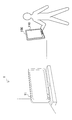
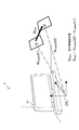
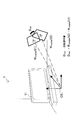
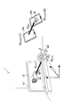
- FIG. 5 is an explanatory diagram for describing an example of an operation of a virtual object executed according to a technique according to the present disclosure.
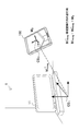
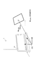
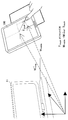
- FIG. It is a block diagram which shows an example of the hardware constitutions of the image processing apparatus which concerns on one Embodiment. It is a block diagram which shows an example of a structure of the logical function of the image processing apparatus which concerns on one Embodiment. It is explanatory drawing which shows a mode that a virtual object is operated along a 1st operation scenario. It is explanatory drawing which shows a mode that a virtual object is operated along a 2nd operation scenario. It is a flowchart which shows an example of the flow of the image processing which concerns on one Embodiment.
- FIG. 1 is an explanatory diagram illustrating an example of an environment to which the technology according to the present disclosure can be applied.
- an environment 1 and an image processing apparatus 100 that captures an image showing the environment 1 are shown.
- an object 11 exists in the environment 1.
- the image processing apparatus 100 typically includes an imaging unit (not shown) and a display unit 110.
- the imaging unit of the image processing apparatus 100 captures a series of images that form a video showing the environment 1.
- the image processing apparatus 100 performs image processing using the captured image as an input image, and arranges a virtual object in the three-dimensional space.
- the virtual object is manipulated by the user by moving the image processing apparatus 100.
- the display unit 110 of the image processing apparatus 100 displays an output image on which a virtual object is superimposed.
- the image processing apparatus 100 arranges the virtual object in some reference environment. That is, the position and orientation of the virtual object are defined in a coordinate system associated with the reference environment (hereinafter referred to as a reference coordinate system).
- a reference coordinate system a coordinate system associated with the reference environment
- the environment 1 including the object 11 is a reference environment.
- the reference environment may be any environment regardless of indoor or outdoor.
- one object having an object-specific coordinate system may be treated as the reference environment. In that case, the coordinate system unique to the object becomes the reference coordinate system.
- FIG. 1 shows a tablet PC as an example of the image processing apparatus 100.
- the image processing apparatus 100 is not limited to such an example.
- the image processing apparatus 100 may be, for example, a notebook PC, a pocket PC, a smartphone, a game terminal, a PND (Portable Navigation Device), a content player, or a digital home appliance.
- the environment recognition matrix is a matrix that represents the position and orientation of the reference environment on the basis of the position and orientation in the reference environment of the terminal that captured the input image.
- the environment recognition matrix may typically be a coordinate transformation matrix (for example, a 4 ⁇ 4 homogeneous transformation matrix) representing translation, rotation, and scaling (enlargement / reduction) in a three-dimensional space.
- a reference coordinate system CS 1 associated with the reference environment 1 and a device-specific coordinate system CS 0 of the image processing apparatus 100 are shown.
- the device-specific coordinate system CS 0 can be constituted by, for example, a two-dimensional coordinate axis and a depth axis of the screen of the display unit 110.
- the relative position and orientation of the reference coordinate system CS 1 with respect to the apparatus-specific coordinate system CS 0 of the image processing apparatus 100 can be recognized using an input image by utilizing a known image recognition technique.
- the image recognition technique utilized here may be, for example, the SfM (Structure from Motion) method, the SLAM (Simultaneous Localization And Mapping) method, or the method described in Non-Patent Document 1 or 2 above. Instead, a simpler environment recognition technique using an infrared sensor may be used.
- the position and orientation of the coordinate system CS 0 unique to the apparatus of the image processing apparatus 100 are expressed by the unit matrix M 0 .
- coordinate transformation an arbitrary position and orientation from the matrices M 0 of the reference environment 1 can be recognized as (parallel movement, rotation and scaling). Therefore, a set of position and orientation is represented by one coordinate transformation matrix.
- the environment recognition matrix described above is one such coordinate transformation matrix.
- the environment recognition matrix M recog represents the position and orientation of the reference coordinate system CS 1 with reference to the position and orientation of the image processing apparatus 100 (that is, the unit matrix M 0 ).
- the inverse matrix M recog ⁇ 1 of the environment recognition matrix M recog represents the position and orientation of the image processing apparatus 100 with reference to the position and orientation of the reference coordinate system CS 1. It becomes a matrix.
- FIG. 3 conceptually shows the coordinate transformation represented by the inverse matrix M recog ⁇ 1 of the environment recognition matrix.
- the operation arrangement matrix M mobile is a matrix expressing the position and orientation of the image processing apparatus 100 moved by the user to operate the virtual object.
- the term “movement” may include both parallel movement and rotation unless specifically indicated as “parallel” movement.
- the operation arrangement matrix M mobile may be equal to the inverse matrix M recog ⁇ 1 of the environment recognition matrix, for example, as in the following equation.
- FIG. 4 conceptually shows the coordinate transformation expressed by the operation arrangement matrix M mobile when Expression (1) is adopted.
- an offset matrix as described below may be used.
- FIG. 5 conceptually shows an operation arrangement matrix M mobile that is determined by including the offset matrix T touch .
- the offset matrix T touch is a coordinate transformation matrix that represents parallel movement in a direction along the screen, which is determined according to the user input position on the screen of the image processing apparatus 100.
- the operation arrangement matrix M mobile can be calculated as follows:
- the user can finely adjust the operation position by performing an operation (for example, touch or click) at a desired position on the screen instead of moving the image processing apparatus 100. Easy to do.
- the difference between the attitude represented by the operation arrangement matrix M mobile (t1) and the attitude represented by the operation arrangement matrix M mobile (t2) indicates a rotation amount corresponding to the rotation of the image processing apparatus 100 from time t1 to time t2.
- a virtual object arranged in the reference environment is three-dimensionally operated according to the parallel movement amount and the rotation amount.
- the operation arrangement matrix M mobile (t1) is determined. Further, at the subsequent time t2, the operation arrangement matrix M mobile (t2) is determined. From these operation arrangement matrices, the parallel movement operation amount D mov is calculated as in the following equation.
- V mobile (t) represents a parallel movement component of the operation arrangement matrix M mobile (t).
- the rotation operation amount D rot is calculated from the two operation arrangement matrices M mobile (t1) and M mobile (t2) as in the following equation.
- R mobile (t) represents a rotation component of the operation arrangement matrix M mobile (t).
- Formula (3) and Formula (4) are only examples.
- the right side of Expression (3) or Expression (4) may be multiplied by a coefficient for amplifying or reducing the operation amount.
- FIG. 8 is an explanatory diagram for describing an example of a virtual object operation performed according to the technique according to the present disclosure.
- the pre- operation matrix M pre illustrated in FIG. 8 is equal to a matrix expressing the position and orientation of the object 11 recognized by the image processing apparatus 100.
- the virtual object 21 is a virtual object associated with the object 11.
- the image processing apparatus 100 determines a three-dimensional operation amount corresponding to the difference between the operation arrangement matrix M mobile (t1) and the operation arrangement matrix M mobile (t2).
- the operation arrangement matrix M mobile t2
- the parallel movement operation amount D mov is determined. Then, the image processing apparatus 100 moves the virtual object 21 according to the parallel movement operation amount D mov .
- the post- operation matrix M post that represents the position and orientation of the virtual object 21 after the operation is Is calculated as follows.
- the post- operation matrix M post is calculated as shown in Equation (6).
- the post- operation matrix M post is calculated as shown in Equation (7).
- the appearance of the virtual object 21 from the image processing apparatus 100 at time t2 is as follows, corresponding to the product of the post- operation matrix M post and the environment recognition matrix M recog (t2) at time t2. It can be expressed as a coordinate transformation.
- the user can freely specify a three-dimensional operation amount by operating a terminal such as the image processing apparatus 100 while moving the terminal.
- a terminal such as the image processing apparatus 100
- the terminal such as the image processing apparatus 100
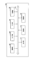
- FIG. 9 is a block diagram illustrating an example of a hardware configuration of the image processing apparatus 100 according to an embodiment.
- the image processing apparatus 100 includes an imaging unit 102, a sensor unit 104, an input unit 106, a storage unit 108, a display unit 110, a communication unit 112, a bus 116, and a control unit 118.
- Imaging unit The imaging unit 102 is a camera module that captures an image.
- the imaging unit 102 images a real space using an imaging element such as a charge coupled device (CCD) or a complementary metal oxide semiconductor (CMOS), and generates a captured image.
- CCD charge coupled device
- CMOS complementary metal oxide semiconductor
- a series of captured images generated by the imaging unit 102 constitutes a video.
- the imaging unit 102 is not necessarily a part of the image processing apparatus 100.
- an imaging apparatus connected to the image processing apparatus 100 by wire or wireless may be handled as the imaging unit 102.
- the imaging unit 102 may include a depth sensor that measures the distance between the imaging unit 102 and the subject for each pixel. The depth data output from the depth sensor can be used for environment recognition.
- the sensor unit 104 can include various sensors such as a positioning sensor, an acceleration sensor, and a gyro sensor.
- the measurement result obtained in the sensor unit 104 may be used for various purposes such as support of environment recognition, acquisition of data specific to a geographical position, or detection of user input. Note that the sensor unit 104 may be omitted from the configuration of the image processing apparatus 100.
- the input unit 106 is an input device used by the user to operate the image processing apparatus 100 or input information to the image processing apparatus 100.
- the input unit 106 may include, for example, a touch sensor that detects a user's touch on the screen of the display unit 110.
- the input unit 106 may include a pointing device such as a mouse or a touchpad.
- the input unit 106 may include other types of input devices such as a keyboard, keypad, buttons, or switches.
- the storage unit 108 is configured by a storage medium such as a semiconductor memory or a hard disk, and stores a program and data for processing by the image processing apparatus 100.
- the data stored by the storage unit 108 may include, for example, captured image data, sensor data, and data in a database (DB) described later.
- DB database
- some of the programs and data described in this specification may be acquired from an external data source (for example, a data server, a network storage, or an external memory) without being stored in the storage unit 108. .
- the display unit 110 is a display module including a display such as an LCD (Liquid Crystal Display), an OLED (Organic light-Emitting Diode), or a CRT (Cathode Ray Tube).
- the display unit 110 is used to display an output image generated by the image processing apparatus 100, for example.
- the display unit 110 is not necessarily a part of the image processing apparatus 100.
- a display device connected to the image processing apparatus 100 by wire or wireless may be handled as the display unit 110.
- the communication unit 112 is a communication interface that mediates communication between the image processing apparatus 100 and other apparatuses.
- the communication unit 112 supports an arbitrary wireless communication protocol or wired communication protocol, and establishes a communication connection with another device.
- Bus The bus 116 connects the imaging unit 102, the sensor unit 104, the input unit 106, the storage unit 108, the display unit 110, the communication unit 112, and the control unit 118 to each other.
- the control unit 118 corresponds to a processor such as a CPU (Central Processing Unit) or a DSP (Digital Signal Processor).
- the control unit 118 operates various functions of the image processing apparatus 100 to be described later by executing a program stored in the storage unit 108 or another storage medium.
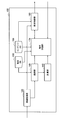
- FIG. 10 is a block diagram illustrating an example of a configuration of logical functions realized by the storage unit 108 and the control unit 118 of the image processing apparatus 100 illustrated in FIG. 9.
- the image processing apparatus 100 includes an image acquisition unit 120, a recognition unit 130, a calculation unit 140, an object DB 150, a content DB 160, an operation control unit 170, and a display control unit 180.
- the image acquisition unit 120 acquires a captured image generated by the imaging unit 102 as an input image.
- the input image acquired by the image acquisition unit 120 may be individual frames constituting a video that reflects the real space.
- the image acquisition unit 120 outputs the acquired input image to the recognition unit 130 and the display control unit 180.
- the recognizing unit 130 recognizes the above-described environment recognition matrix that expresses the position and orientation of the reference environment using the input image input from the image acquisition unit 120.
- the recognition unit 130 can utilize a known image recognition technique such as the SfM method or the SLAM method in order to recognize the environment recognition matrix.
- the recognition unit 130 may recognize the environment recognition matrix based on depth data from a depth sensor that may be provided in the imaging unit 102.
- the recognition unit 130 may recognize an environment recognition matrix based on output data from an environment recognition system such as an infrared distance measuring system or a motion capture system.
- the recognizing unit 130 uses the extended Kalman filter principle as a state variable including the position, posture, velocity and angular velocity of the terminal and the position of one or more feature points reflected in the input image. Update every frame based on. Thereby, the position and orientation of the reference environment based on the position and orientation of the terminal can be recognized using the input image from the monocular camera.
- the recognizing unit 130 represents the recognized position and orientation of the reference environment by an environment recognition matrix M recog corresponding to coordinate conversion from the position and orientation of the terminal.
- Detailed explanation of the SLAM method can be found in “Real-Time Simultaneous Localization and Mapping with a Single Camera” (Andrew J. Davison, Proceedings of the 9th IEEE International Conference on Computer Vision Volume 2, 2003, pp.1403-1410). Are listed.
- the recognition unit 130 outputs the environment recognition matrix M recog recognized in this way to the calculation unit 140 and the operation control unit 170.
- the recognition unit 130 also recognizes the position and orientation of the object shown in the input image.
- the object DB 150 stores in advance the known feature amount data of each of the one or more objects and the identifier of the object. Then, the recognizing unit 130 can identify the object shown in the input image by comparing the feature amount data extracted from the input image with the feature amount data stored in the object DB 150.
- the recognition unit 130 recognizes a coordinate transformation matrix that expresses the position and orientation of the identified object in the reference coordinate system in the same manner as the environment recognition matrix M recog .
- the calculation unit 140 calculates an inverse matrix M recog ⁇ 1 of the environment recognition matrix input from the recognition unit 130.
- the inverse matrix M recog ⁇ 1 of the environment recognition matrix represents coordinate conversion from the position and orientation of the reference coordinate system to the position and orientation of the terminal.
- the calculation unit 140 outputs an inverse matrix M recog ⁇ 1 of the calculated environment recognition matrix to the operation control unit 170.
- the object DB 150 stores in advance known feature amount data and an identifier of an object to be recognized according to the purpose of the AR application.
- the content DB 160 stores in advance an identifier of a virtual object that can be operated by a user, attribute data, and an identifier of an associated object.
- the virtual object attribute data includes display attributes of the virtual object (for example, initial values of position and orientation, shape and color) and operation attributes of the virtual object (for example, whether parallel movement and rotation are possible, respectively). May be included.
- Operation control unit 170 controls the operation of the virtual object arranged in the environment reflected in the input image using the various parameters described above.
- the operation control unit 170 at a first time corresponding to the start of the operation, based on the inverse matrix M recog ⁇ 1 of the environment recognition matrix, the operation arrangement that represents the operation position and orientation in the three-dimensional reference environment
- the matrix M mobile is determined.
- the operation control unit 170 may determine an operation arrangement matrix M mobile equal to the inverse matrix M recog ⁇ 1 of the environment recognition matrix according to the above equation (1).
- the operation control unit 170 may determine the operation arrangement matrix M mobile by adding an offset matrix corresponding to the user input position on the terminal screen according to the above equation (2).
- the operation control unit 170 identifies a virtual object to be operated.
- the virtual object to be operated may be an object associated with an object selected on the basis of some criterion from among objects reflected in the input image. Further, the virtual object to be operated may be an object designated by the user (for example, by touch or click) on the screen.
- the operation control unit 170 based on the inverse matrix M recog ⁇ 1 of the environment recognition matrix, at the second time point corresponding to the end of the operation (may be in the middle of the operation), According to the equation (2), the operation arrangement matrix M mobile that represents the operation position and posture in the three-dimensional reference environment is determined again.
- the operation control unit 170 determines the operation amount of the virtual object according to the difference between the two operation arrangement matrices M mobile at the start and end of the operation. For example, it is assumed that the data stored in the content DB 160 indicates that the virtual object to be operated can be moved in parallel. Then, the operation control unit 170 calculates the parallel movement operation amount D mov according to the difference between the parallel movement components of the two operation arrangement matrices M mobile . Further, it is assumed that the data stored in the content DB 160 indicates that the virtual object to be operated can be rotated. Then, the operation control unit 170 calculates the rotation operation amount D rot according to the difference between the rotation components of the two operation arrangement matrices M mobile .
- the operation control unit 170 When the operation control unit 170 calculates these operation amounts, the operation control unit 170 changes the arrangement of the virtual objects to be operated according to the calculated operation amount.
- the relationship between the placement of the virtual objects before and after the operation may be any one of the above formulas (6) to (8).
- the operation control unit 170 outputs to the display control unit 180 a coordinate transformation matrix ( post- operation matrix M post ) that expresses the placement of the virtual object that is updated according to the operation by the user.
- the first time point corresponding to the start of the operation may be a time point when the first user input is detected at the terminal, and the second time point corresponding to the end of the operation is the second time point at the terminal. It may be the time when the user input is detected.
- the operation control unit 170 can distinguish between the user's action intended to operate the virtual object and other actions.
- These first and second user inputs may be defined to correspond to the start and end of a series of operations, respectively.
- the series of operations can correspond to, for example, touch or drag.
- the start of touch or drag is detected as a Press event
- the end of touch or drag is detected as a Release event.
- the user can move and rotate the virtual object three-dimensionally as intended by only a simple operation of moving the terminal while touching (or dragging) the screen. it can.
- the virtual object to be operated may be specified based on the first user input described above corresponding to the start of the operation. For example, when the virtual object to be operated is specified based on the press position on the screen at the start of the operation, an intuitive user interface is realized in which the virtual object is dragged and moved in the three-dimensional space. .
- user input is not limited to the example described above.
- pressing a predetermined key or button, touch gesture recognition, facial expression recognition, voice command recognition, or gaze recognition on a head mounted display may be defined as user input.
- the display control unit 180 generates an output image by superimposing a virtual object on the input image according to the arrangement by the operation control unit 170. Then, the display control unit 180 displays the generated output image on the screen of the display unit 110.
- the display trigger of the virtual object may be, for example, detection of some user input, reception of virtual object data from another device, or recognition of some pattern in the input image.
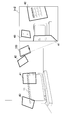
- FIG. 11 shows a state in which a new virtual object is arranged in the reference environment according to the first operation scenario.
- the object 11 in the reference environment 1 is a digital television device.
- a content image showing the lion 12 is displayed on the screen of the digital television apparatus 11.
- feature amount data of the lion 12 is stored in advance.
- the lion 12 appears in the input image.
- the recognition unit 130 identifies the lion 12 shown in the input image using the feature amount data stored in the object DB 150.
- the operation control part 170 specifies the virtual object 22 linked
- the virtual object 22 is assumed to be movable in parallel, for example.
- the operation control unit 170 calculates a parallel movement operation amount D mov that is a difference in parallel movement components between the two operation arrangement matrices M mobile (t1) and M mobile (t2) before and after the movement. Then, the operation control unit 170 calculates a post- operation matrix M post expressing the position and posture of the virtual object 22 after the operation from the position and posture of the lion 12 and the parallel movement operation amount D mov .
- the display control unit 180 projects the virtual object 22 having a three-dimensional position and orientation represented by the post- operation matrix M post on a two-dimensional screen, and displays an output image on which the virtual object 22 is superimposed.
- FIG. 12 shows a state in which a virtual object that has been arranged is operated by the user according to the second operation scenario.
- the object 11 in the reference environment 1 is a digital television device.
- the object DB 150 feature data of the digital television device 11 is stored in advance.
- the content DB 160 stores data of the virtual object 23 associated with the digital television device 11 in advance.
- the virtual object 23 is, for example, a virtual panel that displays information about the digital television device 11.
- the virtual object 23 is placed in the AR space at the position and orientation represented by the pre- operation matrix M pre .
- the virtual object 23 appears in the input image.
- the operation control unit 170 specifies the virtual object 23 as the virtual object to be operated.
- the virtual object 23 is assumed to be rotatable, for example.
- the operation control unit 170 calculates a rotation operation amount D rot that is a difference in rotation components between the two operation arrangement matrices M mobile (t3) and M mobile (t4) before and after the movement. Then, the operation control unit 170 rearranges the virtual object 23 so that the virtual object 23 has the position and orientation represented by the post- operation matrix M post calculated from the pre- operation matrix M pre and the rotation operation amount D rot. To do.
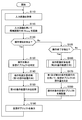
- FIG. 13 is a flowchart illustrating an example of the flow of image processing by the image processing apparatus 100.
- the image acquisition unit 120 acquires a captured image generated by the imaging unit 102 as an input image (step S110). Then, the image acquisition unit 120 outputs the acquired input image to the recognition unit 130 and the display control unit 180.
- the recognition unit 130 recognizes an environment recognition matrix M recog that represents the position and orientation of the reference environment using the input image input from the image acquisition unit 120 (step S115). Then, the recognition unit 130 outputs the recognized environment recognition matrix M recog to the calculation unit 140, the operation control unit 170, and the display control unit 180.
- step S130 step S120
- step S160 step S125
- step S130 the operation control unit 170 specifies a virtual object to be operated (step S130).
- the number of virtual objects specified here may be one or plural.
- step S140 the operation arrangement calculation process described with reference to FIG. 14 is executed, and a first operation arrangement matrix is calculated (step S140). Then, the calculated first operation arrangement matrix is stored (step S150).
- step S160 an operation arrangement calculation process described with reference to FIG. 14 is executed to calculate a second operation arrangement matrix (step S160).
- the operation control unit 170 determines the operation amount of the virtual object to be operated using the first and second operation arrangement matrices (step S170). Then, the operation control unit 170 rearranges the operation target virtual object according to the determined operation amount (step S180).
- the display control unit 180 generates an output image on which the virtual object to be operated and other virtual objects to be displayed are superimposed, and displays the generated output image on the screen of the display unit 110 (step S190).
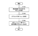
- FIG. 14 is a flowchart showing an example of a detailed flow of the operation arrangement calculation process corresponding to steps S140 and S160 of FIG.
- the calculation unit 140 calculates an inverse matrix M recog ⁇ 1 of the environment recognition matrix input from the recognition unit 130 (step S142). Further, the operation control unit 170 determines an offset matrix T touch in accordance with the user input position on the terminal screen (step S144). If an offset matrix is not used, the process of step S144 may be omitted. Then, the operation control unit 170 determines an operation arrangement matrix M mobile based on the inverse matrix M recog ⁇ 1 of the environment recognition matrix and the offset matrix T touch (step S146).
- the virtual object may be displayed in various forms. In this section, various display variations of the virtual object will be described.
- the virtual object may have a predefined reference plane.
- one surface can be defined as a reference surface and the other surface as a non-reference surface.
- the reference plane of the virtual object can be identified by a normal vector that goes outward from the reference plane.
- the display control unit 180 may change the display of the virtual object according to whether or not the reference plane of the virtual object is reflected on the screen of the image processing apparatus 100. .
- the display control unit 180 can set display attributes such as the shape, scale, transparency, color, resolution, or edge thickness of the virtual object 32 to values different from the virtual object 31. Further, the display control unit 180 may change the content of the information indicated by the virtual objects 31 and 32 according to whether or not the reference plane is reflected.
- the user can easily grasp which direction the displayed virtual object is facing.
- the user wants to browse the content of information displayed on the reference plane of the virtual object 31.
- the user turns around the terminal where the reference plane of the virtual object 31 can be seen and holds the terminal.
- the user simply rotates the terminal of the virtual object 31 three-dimensionally by designating the virtual object 31 on the screen and rotating the terminal on the spot. The contents of information displayed on the reference plane can be easily browsed.
- the display control unit 180 may change the display of the virtual object according to the distance between the image processing apparatus 100 and the virtual object.
- the display control unit 180 can emphasize the display attributes of the virtual objects 41 and 42 so that the virtual objects 41 and 42 are visually recognized by the user more clearly. Further, the display control unit 180 may display more detailed information about the virtual objects 41 and 42.
- the virtual object (or the content of the display content) of the virtual object that the user is more interested in (that is, close to the terminal) ) Visibility can be improved.
- the user desires to browse the contents of information displayed by the virtual object 43 in detail. Without the technology according to the present disclosure, the user will try to hold the terminal while approaching the virtual object 43 more closely. However, according to the technology according to the present disclosure, the user simply moves the position of the virtual object 43 forward by designating the virtual object 43 on the screen and pulling the terminal, and the virtual object 43 is displayed. You can browse the contents of the information in more detail.
- the display control unit 180 may rearrange the plurality of virtual objects so that the plurality of virtual objects to be displayed are aligned with a predetermined interval when a predetermined condition is satisfied.
- the display control unit 180 aligns these virtual objects when a predetermined user input is detected.
- the four virtual objects 51, 52, 53, and 54 located closer to the image processing apparatus 100 are rearranged so as to be aligned at a predetermined interval.
- the predetermined condition for rearranging the virtual objects may be, for example, that the number of virtual objects in the screen exceeds a predetermined threshold instead of the user input.
- the operation control unit 170 may control the operations of the virtual objects arranged in this way according to the mechanism described above.
- the terminal used for operating the virtual object is the same as the terminal displaying the operated virtual object.
- the technology according to the present disclosure is not limited to such an example.
- a virtual object operated using a certain terminal may be displayed on the screen of another terminal. In this section, sharing of such virtual objects will be described.
- an image processing system including an image processing device 100a and an image processing device 100b for sharing a virtual object between users is shown.
- the image processing apparatus 100a according mechanism described above, in the reference environment 2 with a reference coordinate system CS 2, to determine the placement of the virtual object in response to operation by the user.
- a virtual object 61 simulating a car is arranged on a table 62 that is a real object.
- the virtual object 61 is movable according to an operation amount (for example, a parallel movement operation amount D mov ) determined in the image processing apparatus 100a, for example.
- the image processing device 100a transmits data representing the arrangement of the virtual object 61 (for example, the post- operation matrix M post described above) to the image processing device 100b.
- the image processing apparatus 100b recognizes an environment recognition matrix expressing the position and orientation of the reference environment 2 shown in the input image, and uses the recognized environment recognition matrix and the post- operation matrix M post received from the image processing apparatus 100a.
- the virtual object 61 is superimposed on the input image.
- the environment 2 corresponding to one space including the table 62 is shown as the reference environment.
- the reference environment to which the technology according to the present disclosure is applied is not limited to such an environment.
- a common feature point group or object exists between these spaces, or calibration can be performed.
- a plurality of environments corresponding to these spaces may be treated as one common reference environment.
- environments recognized at different times in one space may be treated as one common reference environment.
- the image processing apparatus 100a and the book 63a exist in the environment 3a.
- the image processing apparatus 100b and the book 63b exist in the environment 3b.
- the book 63a and the book 63b have a common feature point group. Accordingly, the image processing apparatus 100a and 100b may use their feature point group recognize a single common reference coordinate system CS 3, share a virtual object associated with the reference coordinate system CS 3.
- a virtual object 73 simulating an elephant is arranged in the vicinity of the book 63a.
- the virtual object 73 can be rotated according to an operation amount (for example, a rotation operation amount D rot ) determined in the image processing apparatus 100a.
- the image processing device 100b transmits data representing the arrangement of the virtual object 73 (for example, the post- operation matrix M post described above) to the image processing device 100b.
- the image processing apparatus 100b recognizes an environment recognition matrix that represents the position and orientation of the reference environment 3b shown in the input image, and uses the recognized environment recognition matrix and the post- operation matrix M post received from the image processing apparatus 100a.
- the output image on which the virtual object 73 is superimposed is displayed.
- the environment recognition matrix expressing the position and orientation of the environment is recognized on the basis of the position and orientation of the terminal in the reference environment, and the position of the terminal is based on the inverse matrix of the recognized environment recognition matrix. And the posture is expressed. Then, the virtual object arranged in the reference environment is operated with a three-dimensional operation amount corresponding to the difference between one or both of the position and orientation of the terminal at two points in time. Therefore, the user can freely operate the virtual object in three dimensions in the AR space by moving the terminal in the three-dimensional space. For example, when a portable terminal is used, the user can move the virtual object three-dimensionally and rotate the virtual object three-dimensionally by holding and moving the portable terminal.
- the virtual object to be operated is specified based on the user input position on the screen at the start of a series of operations.
- a series of control processing by each device described in this specification may be realized using any of software, hardware, and a combination of software and hardware.
- a program constituting the software is stored in advance in a storage medium provided inside or outside each device.
- Each program is read into a RAM (Random Access Memory) at the time of execution and executed by a processor such as a CPU.
- RAM Random Access Memory
- some of the logical functions of each device may be implemented on a device existing in the cloud computing environment instead of being implemented on the device.
- information exchanged between logical functions can be transmitted or received between devices via the communication unit 112 illustrated in FIG.
- a recognition unit for recognizing an environment recognition matrix expressing the position and orientation of the environment reflected in the image based on the position and orientation of the terminal that captured the image;
- a calculation unit for calculating an inverse matrix of the environment recognition matrix;
- a first position or first attitude based on the inverse matrix of the environment recognition matrix recognized at a first time point, and a first position based on the inverse matrix of the environment recognition matrix recognized at a subsequent second time point.
- An operation control unit that controls an operation of a virtual object arranged in the environment with a three-dimensional operation amount according to a difference between the position of 2 or the second posture;
- An image processing apparatus comprising: (2) The image processing apparatus according to (1), wherein the operation amount is a parallel movement amount corresponding to a difference between the first position and the second position. (3) The image processing apparatus according to (1), wherein the operation amount is a rotation amount corresponding to a difference between the first posture and the second posture.
- the first time point is a time point when a first user input is detected at the terminal;
- the second time point is a time point when a second user input is detected at the terminal.
- the image processing apparatus according to any one of (1) to (3).
- the first position or the second position is a position that is offset in a direction along the screen according to a user input position on the screen of the terminal.
- the operation control unit specifies the virtual object to be operated based on the first user input.
- the operation control unit specifies a virtual object associated with an object in the environment specified by the first user input as the virtual object to be operated.
- the image processing apparatus according to item. (10) Recognizing an environment recognition matrix expressing the position and orientation of the environment shown in the image based on the position and orientation of the terminal that captured the image; Calculating an inverse matrix of the environment recognition matrix; A first position or first attitude based on the inverse matrix of the environment recognition matrix recognized at a first time point, and a first position based on the inverse matrix of the environment recognition matrix recognized at a subsequent second time point.
- An image processing method including: (11) Computer A recognition unit for recognizing an environment recognition matrix expressing the position and orientation of the environment reflected in the image based on the position and orientation of the terminal that captured the image; A calculation unit for calculating an inverse matrix of the environment recognition matrix; A first position or first attitude based on the inverse matrix of the environment recognition matrix recognized at a first time point, and a first position or first posture based on the inverse matrix of the environment recognition matrix recognized at a second time point that follows An operation control unit that controls an operation of a virtual object arranged in the environment with a three-dimensional operation amount according to a difference between the position of 2 or the second posture; Program to function as.
- Image processing device 120 image acquisition unit 130 recognition unit 140 calculation unit 170 operation control unit 180 display control unit
Landscapes
- Engineering & Computer Science (AREA)
- Theoretical Computer Science (AREA)
- General Engineering & Computer Science (AREA)
- Physics & Mathematics (AREA)
- General Physics & Mathematics (AREA)
- Human Computer Interaction (AREA)
- Computer Hardware Design (AREA)
- Architecture (AREA)
- Computer Graphics (AREA)
- Software Systems (AREA)
- User Interface Of Digital Computer (AREA)
- Processing Or Creating Images (AREA)
Abstract
Description
1.基本的な原理
1-1.概要
1-2.基本的なパラメータ
1-3.3次元的な操作量の例
2.画像処理装置の構成例
2-1.ハードウェア構成
2-2.機能構成
2-3.操作シナリオ
2-4.処理の流れ
2-5.表示のバリエーション
2-6.仮想オブジェクトの共有
3.まとめ
まず、図1~図8を用いて、本開示に係る技術の基本的な原理について説明する。
図1は、本開示に係る技術が適用され得る環境の一例を示す説明図である。図1を参照すると、環境1、及び環境1を映す画像を撮像する画像処理装置100が示されている。図1の例において、環境1には、物体11が存在している。画像処理装置100は、典型的には、撮像部(図示せず)及び表示部110を備える。画像処理装置100の撮像部は、環境1を映す映像を構成する一連の画像を撮像する。そして、画像処理装置100は、撮像画像を入力画像として画像処理を行い、3次元空間に仮想オブジェクトを配置する。仮想オブジェクトは、後に説明するように、画像処理装置100を動かすことによりユーザにより操作される。画像処理装置100の表示部110は、仮想オブジェクトが重畳された出力画像を表示する。
本開示に係る技術において、基準環境内に配置される仮想オブジェクトの位置及び姿勢は、いくつかのパラメータを用いた計算を通じて決定される。最も基本的なパラメータは、環境認識行列である。
環境認識行列は、入力画像を撮像した端末の基準環境内の位置及び姿勢を基準として、基準環境の位置及び姿勢を表現する行列である。環境認識行列は、典型的には、3次元空間内の並行移動、回転及びスケーリング(拡大/縮小)を表す座標変換行列(例えば、4行4列の同次変換行列)であってよい。
上述した前提の下で、環境認識行列Mrecogの逆行列Mrecog -1は、基準座標系CS1の位置及び姿勢を基準とした画像処理装置100の位置及び姿勢を表現する行列となる。図3は、環境認識行列の逆行列Mrecog -1が表現する座標変換を概念的に示している。

図5は、オフセット行列Ttouchを算入して決定される操作配置行列Mmobileを概念的に示している。オフセット行列Ttouchは、画像処理装置100の画面上でのユーザ入力位置に応じて決定される、当該画面に沿った方向への並行移動を表現する座標変換行列である。オフセット行列Ttouchが算入される場合、操作配置行列Mmobileは、次式のように計算され得る。

ここで、ユーザが、時刻t1から時刻t2にかけて画像処理装置100を移動させたものとする。その場合、上述した原理に従って、時刻t1における操作配置行列Mmobile(t1)と時刻t2における操作配置行列Mmobile(t2)とを計算することができる。操作配置行列Mmobile(t1)が表現する位置と操作配置行列Mmobile(t2)が表現する位置との差分は、時刻t1から時刻t2にかけての画像処理装置100の並行移動(及び画面上でのユーザ入力位置の変化)に対応する並行移動量を示す。操作配置行列Mmobile(t1)が表現する姿勢と操作配置行列Mmobile(t2)が表現する姿勢との差分は、時刻t1から時刻t2にかけての画像処理装置100の回転に対応する回転量を示す。本開示に係る技術では、これら並行移動量及び回転量に従って、基準環境内に配置される仮想オブジェクトが3次元的に操作される。





[2-1.ハードウェア構成]
図9は、一実施形態に係る画像処理装置100のハードウェア構成の一例を示すブロック図である。図9を参照すると、画像処理装置100は、撮像部102、センサ部104、入力部106、記憶部108、表示部110、通信部112、バス116及び制御部118を備える。
撮像部102は、画像を撮像するカメラモジュールである。撮像部102は、CCD(Charge Coupled Device)又はCMOS(Complementary Metal Oxide Semiconductor)などの撮像素子を用いて実空間を撮像し、撮像画像を生成する。撮像部102により生成される一連の撮像画像は、映像を構成する。なお、撮像部102は、必ずしも画像処理装置100の一部でなくてもよい。例えば、画像処理装置100と有線又は無線で接続される撮像装置が撮像部102として扱われてもよい。また、撮像部102は、撮像部102と被写体との間の距離を画素ごとに測定する深度(depth)センサを含んでいてもよい。深度センサから出力される深度データは、環境の認識のために利用され得る。
センサ部104は、測位センサ、加速度センサ及びジャイロセンサなどの様々なセンサを含み得る。センサ部104において得られる測定結果は、環境の認識の支援、地理的な位置に特化したデータの取得、又はユーザ入力の検出などの様々な用途のために利用されてよい。なお、センサ部104は、画像処理装置100の構成から省略されてもよい。
入力部106は、ユーザが画像処理装置100を操作し又は画像処理装置100へ情報を入力するために使用される入力デバイスである。入力部106は、例えば、表示部110の画面上へのユーザによるタッチを検出するタッチセンサを含んでもよい。その代わりに(又はそれに加えて)、入力部106は、マウス若しくはタッチパッドなどのポインティングデバイスを含んでもよい。さらに、入力部106は、キーボード、キーパッド、ボタン又はスイッチなどのその他の種類の入力デバイスを含んでもよい。
記憶部108は、半導体メモリ又はハードディスクなどの記憶媒体により構成され、画像処理装置100による処理のためのプログラム及びデータを記憶する。記憶部108により記憶されるデータは、例えば、撮像画像データ、センサデータ及び後に説明するデータベース(DB)内のデータを含み得る。なお、本明細書で説明するプログラム及びデータの一部は、記憶部108により記憶されることなく、外部のデータソース(例えば、データサーバ、ネットワークストレージ又は外付けメモリなど)から取得されてもよい。
表示部110は、LCD(Liquid Crystal Display)、OLED(Organic light-Emitting Diode)又はCRT(Cathode Ray Tube)などのディスプレイを含む表示モジュールである。表示部110は、例えば、画像処理装置100により生成される出力画像を表示するために使用される。なお、表示部110もまた、必ずしも画像処理装置100の一部でなくてもよい。例えば、画像処理装置100と有線又は無線で接続される表示装置が表示部110として扱われてもよい。
通信部112は、画像処理装置100による他の装置との間の通信を仲介する通信インタフェースである。通信部112は、任意の無線通信プロトコル又は有線通信プロトコルをサポートし、他の装置との間の通信接続を確立する。
バス116は、撮像部102、センサ部104、入力部106、記憶部108、表示部110、通信部112及び制御部118を相互に接続する。
制御部118は、CPU(Central Processing Unit)又はDSP(Digital Signal Processor)などのプロセッサに相当する。制御部118は、記憶部108又は他の記憶媒体に記憶されるプログラムを実行することにより、後に説明する画像処理装置100の様々な機能を動作させる。
図10は、図9に示した画像処理装置100の記憶部108及び制御部118により実現される論理的機能の構成の一例を示すブロック図である。図10を参照すると、画像処理装置100は、画像取得部120、認識部130、計算部140、物体DB150、コンテンツDB160、操作制御部170及び表示制御部180を備える。
画像取得部120は、撮像部102により生成される撮像画像を入力画像として取得する。画像取得部120により取得される入力画像は、実空間を映す映像を構成する個々のフレームであってよい。画像取得部120は、取得した入力画像を、認識部130及び表示制御部180へ出力する。
認識部130は、画像取得部120から入力される入力画像を用いて、基準環境の位置及び姿勢を表現する上述した環境認識行列を認識する。認識部130は、環境認識行列を認識するために、SfM法又はSLAM法などの公知の画像認識技術を活用し得る。その代わりに又はそれに加えて、認識部130は、撮像部102に設けられ得る深度センサからの深度データに基づいて、環境認識行列を認識してもよい。また、認識部130は、赤外線測距システム又はモーションキャプチャシステムなどの環境認識システムからの出力データに基づいて、環境認識行列を認識してもよい。
計算部140は、認識部130から入力される環境認識行列の逆行列Mrecog -1を計算する。例えば、環境認識行列Mrecogは、4行4列の同次変換行列である。従って、環境認識行列の逆行列Mrecog -1もまた4行4列の同次変換行列であり、Mrecog・Mrecog -1=M0(単位行列)を満たす。環境認識行列の逆行列Mrecog -1は、基準座標系の位置及び姿勢から端末の位置及び姿勢への座標変換を表現する。計算部140は、計算した環境認識行列の逆行列Mrecog -1を操作制御部170へ出力する。
物体DB150は、上述したように、ARアプリケーションの目的に応じて認識されるべき物体の既知の特徴量データと識別子とを予め記憶する。
コンテンツDB160は、ユーザにより操作可能な仮想オブジェクトの識別子、属性データ及び関連付けられる物体の識別子を予め記憶する。仮想オブジェクトの属性データは、仮想オブジェクトの表示属性(例えば、位置及び姿勢の初期値、形状並びに色など)と、仮想オブジェクトの操作属性(例えば、並行移動及び回転がそれぞれ可能か、など)とを含み得る。
操作制御部170は、上述した様々なパラメータを用いて、入力画像に映る環境内に配置される仮想オブジェクトの操作を制御する。
表示制御部180は、操作制御部170による配置に従って、仮想オブジェクトを入力画像に重畳することにより、出力画像を生成する。そして、表示制御部180は、生成した出力画像を表示部110の画面に表示させる。仮想オブジェクトの表示のトリガは、例えば、何らかのユーザ入力の検出、他の装置からの仮想オブジェクトのデータの受信、又は入力画像内の何らかのパターンの認識などであってよい。
次に、図11及び図12を用いて、仮想オブジェクトの操作に関する2つの操作シナリオを説明する。第1の操作シナリオでは、仮想オブジェクトが、画像内で認識される物体から引き出されるように新たに配置される。第2の操作シナリオでは、配置済みの仮想オブジェクトがユーザによる操作を通じて移動される。
図11は、第1の操作シナリオに沿って、新たな仮想オブジェクトが基準環境内に配置される様子を示している。
図12は、第2の操作シナリオに沿って、配置済みの仮想オブジェクトがユーザにより操作される様子を示している。
図13は、画像処理装置100による画像処理の流れの一例を示すフローチャートである。
本開示に係る技術において、仮想オブジェクトは、様々な形態で表示され得る。本項では、仮想オブジェクトの様々な表示のバリエーションについて説明する。
ここまでの説明では、仮想オブジェクトの操作に用いられる端末と操作される仮想オブジェクトを表示する端末とが同一であった。しかしながら、本開示に係る技術は、かかる例に限定されない。例えば、ある端末を用いて操作される仮想オブジェクトが、他の端末の画面に表示されてもよい。本項では、そのような仮想オブジェクトの共有について説明する。
ここまで、図1~図19Bを用いて、本開示に係る技術の一実施形態について詳細に説明した。上述した実施形態によれば、基準環境内の端末の位置及び姿勢を基準として環境の位置及び姿勢を表現する環境認識行列が認識され、認識された環境認識行列の逆行列に基づいて端末の位置及び姿勢が表現される。そして、2つの時点の端末の位置及び姿勢の一方又は双方の差分に応じた3次元的な操作量で、基準環境内に配置される仮想オブジェクトが操作される。従って、ユーザは、端末を3次元空間内で動かすことにより、AR空間内で仮想オブジェクトを3次元的に自在に操作することができる。例えば、携帯端末が使用される場合には、ユーザは、当該携帯端末を持って動かすことにより、仮想オブジェクトを3次元的に移動させ、及び仮想オブジェクトを3次元的に回転させることができる。
(1)
画像を撮像した端末の位置及び姿勢を基準として前記画像に映る環境の位置及び姿勢を表現する環境認識行列を認識する認識部と、
前記環境認識行列の逆行列を計算する計算部と、
第1の時点で認識される前記環境認識行列の前記逆行列に基づく第1の位置又は第1の姿勢と、後続する第2の時点で認識される前記環境認識行列の前記逆行列に基づく第2の位置又は第2の姿勢との間の差分に応じた3次元的な操作量で、前記環境内に配置される仮想オブジェクトの操作を制御する操作制御部と、
を備える画像処理装置。
(2)
前記操作量は、前記第1の位置と前記第2の位置との間の差分に応じた並行移動量である、前記(1)に記載の画像処理装置。
(3)
前記操作量は、前記第1の姿勢と前記第2の姿勢との間の差分に応じた回転量である、前記(1)に記載の画像処理装置。
(4)
前記第1の時点は、前記端末において第1のユーザ入力が検出された時点であり、
前記第2の時点は、前記端末において第2のユーザ入力が検出された時点である、
前記(1)~(3)のいずれか1項に記載の画像処理装置。
(5)
前記第1のユーザ入力及び前記第2のユーザ入力は、一連の操作の開始及び終了にそれぞれ対応する、前記(4)に記載の画像処理装置。
(6)
前記第1の位置又は前記第2の位置は、前記端末の画面上でのユーザ入力位置に応じて当該画面に沿った方向にオフセットされる位置である、前記(4)又は前記(5)に記載の画像処理装置。
(7)
前記操作制御部は、前記第1のユーザ入力に基づいて、操作すべき前記仮想オブジェクトを特定する、前記(4)~(6)のいずれか1項に記載の画像処理装置。
(8)
前記操作制御部は、前記第1のユーザ入力によって指定される前記環境内の物体と関連付けられる仮想オブジェクトを、操作すべき前記仮想オブジェクトとして特定する、前記(7)に記載の画像処理装置。
(9)
前記認識部、前記計算部及び前記操作制御部のうち少なくとも1つが前記画像処理装置の代わりにクラウドコンピューティング環境上に存在する装置により実現される、前記(1)~(8)のいずれか1項に記載の画像処理装置。
(10)
画像を撮像した端末の位置及び姿勢を基準として前記画像に映る環境の位置及び姿勢を表現する環境認識行列を認識することと、
前記環境認識行列の逆行列を計算することと、
第1の時点で認識される前記環境認識行列の前記逆行列に基づく第1の位置又は第1の姿勢と、後続する第2の時点で認識される前記環境認識行列の前記逆行列に基づく第2の位置又は第2の姿勢との間の差分に応じた3次元的な操作量で、前記環境内に配置される仮想オブジェクトの操作を制御することと、
を含む画像処理方法。
(11)
コンピュータを、
画像を撮像した端末の位置及び姿勢を基準として前記画像に映る環境の位置及び姿勢を表現する環境認識行列を認識する認識部と、
前記環境認識行列の逆行列を計算する計算部と、
第1の時点で認識される前記環境認識行列の前記逆行列に基づく第1の位置又は第1の姿勢と、後続する第2の時点で認識される前記環境認識行列の前記逆行列に基づく第2の位置又は第2の姿勢との間の差分に応じた3次元的な操作量で、前記環境内に配置される仮想オブジェクトの操作を制御する操作制御部と、
として機能させるためのプログラム。
120 画像取得部
130 認識部
140 計算部
170 操作制御部
180 表示制御部
Claims (11)
- 画像を撮像した端末の位置及び姿勢を基準として前記画像に映る環境の位置及び姿勢を表現する環境認識行列を認識する認識部と、
前記環境認識行列の逆行列を計算する計算部と、
第1の時点で認識される前記環境認識行列の前記逆行列に基づく第1の位置又は第1の姿勢と、後続する第2の時点で認識される前記環境認識行列の前記逆行列に基づく第2の位置又は第2の姿勢との間の差分に応じた3次元的な操作量で、前記環境内に配置される仮想オブジェクトの操作を制御する操作制御部と、
を備える画像処理装置。 - 前記操作量は、前記第1の位置と前記第2の位置との間の差分に応じた並行移動量である、請求項1に記載の画像処理装置。
- 前記操作量は、前記第1の姿勢と前記第2の姿勢との間の差分に応じた回転量である、請求項1に記載の画像処理装置。
- 前記第1の時点は、前記端末において第1のユーザ入力が検出された時点であり、
前記第2の時点は、前記端末において第2のユーザ入力が検出された時点である、
請求項1に記載の画像処理装置。 - 前記第1のユーザ入力及び前記第2のユーザ入力は、一連の操作の開始及び終了にそれぞれ対応する、請求項4に記載の画像処理装置。
- 前記第1の位置又は前記第2の位置は、前記端末の画面上でのユーザ入力位置に応じて当該画面に沿った方向にオフセットされる位置である、請求項4に記載の画像処理装置。
- 前記操作制御部は、前記第1のユーザ入力に基づいて、操作すべき前記仮想オブジェクトを特定する、請求項4に記載の画像処理装置。
- 前記操作制御部は、前記第1のユーザ入力によって指定される前記環境内の物体と関連付けられる仮想オブジェクトを、操作すべき前記仮想オブジェクトとして特定する、請求項7に記載の画像処理装置。
- 前記認識部、前記計算部及び前記操作制御部のうち少なくとも1つが前記画像処理装置の代わりにクラウドコンピューティング環境上に存在する装置により実現される、請求項1に記載の画像処理装置。
- 画像を撮像した端末の位置及び姿勢を基準として前記画像に映る環境の位置及び姿勢を表現する環境認識行列を認識することと、
前記環境認識行列の逆行列を計算することと、
第1の時点で認識される前記環境認識行列の前記逆行列に基づく第1の位置又は第1の姿勢と、後続する第2の時点で認識される前記環境認識行列の前記逆行列に基づく第2の位置又は第2の姿勢との間の差分に応じた3次元的な操作量で、前記環境内に配置される仮想オブジェクトの操作を制御することと、
を含む画像処理方法。 - コンピュータを、
画像を撮像した端末の位置及び姿勢を基準として前記画像に映る環境の位置及び姿勢を表現する環境認識行列を認識する認識部と、
前記環境認識行列の逆行列を計算する計算部と、
第1の時点で認識される前記環境認識行列の前記逆行列に基づく第1の位置又は第1の姿勢と、後続する第2の時点で認識される前記環境認識行列の前記逆行列に基づく第2の位置又は第2の姿勢との間の差分に応じた3次元的な操作量で、前記環境内に配置される仮想オブジェクトの操作を制御する操作制御部と、
として機能させるためのプログラム。
Priority Applications (4)
| Application Number | Priority Date | Filing Date | Title |
|---|---|---|---|
| EP12868009.7A EP2814000B1 (en) | 2012-02-10 | 2012-11-29 | Image processing apparatus, image processing method, and program |
| CN201280068780.2A CN104081307B (zh) | 2012-02-10 | 2012-11-29 | 图像处理装置、图像处理方法和程序 |
| JP2013557372A JP5807686B2 (ja) | 2012-02-10 | 2012-11-29 | 画像処理装置、画像処理方法及びプログラム |
| US14/358,459 US9268410B2 (en) | 2012-02-10 | 2012-11-29 | Image processing device, image processing method, and program |
Applications Claiming Priority (2)
| Application Number | Priority Date | Filing Date | Title |
|---|---|---|---|
| JP2012-026870 | 2012-02-10 | ||
| JP2012026870 | 2012-02-10 |
Publications (1)
| Publication Number | Publication Date |
|---|---|
| WO2013118373A1 true WO2013118373A1 (ja) | 2013-08-15 |
Family
ID=48947160
Family Applications (1)
| Application Number | Title | Priority Date | Filing Date |
|---|---|---|---|
| PCT/JP2012/080863 Ceased WO2013118373A1 (ja) | 2012-02-10 | 2012-11-29 | 画像処理装置、画像処理方法及びプログラム |
Country Status (5)
| Country | Link |
|---|---|
| US (1) | US9268410B2 (ja) |
| EP (1) | EP2814000B1 (ja) |
| JP (1) | JP5807686B2 (ja) |
| CN (1) | CN104081307B (ja) |
| WO (1) | WO2013118373A1 (ja) |
Cited By (6)
| Publication number | Priority date | Publication date | Assignee | Title |
|---|---|---|---|---|
| WO2015041079A1 (ja) * | 2013-09-17 | 2015-03-26 | ソニー株式会社 | 情報処理装置、情報処理方法及びコンピュータプログラム |
| JP2017041068A (ja) * | 2015-08-19 | 2017-02-23 | 富士通株式会社 | 表示制御方法、情報処理装置及び表示制御プログラム |
| JP2018517967A (ja) * | 2015-08-26 | 2018-07-05 | グーグル エルエルシー | 仮想現実における、頭部、ジェスチャ、およびタッチ入力の動的な切り替えならびにマージ |
| JP2020531985A (ja) * | 2017-08-31 | 2020-11-05 | アップル インコーポレイテッドApple Inc. | 拡張現実環境及び仮想現実環境と相互作用するためのシステム、方法、及びグラフィカルユーザインタフェース |
| JP2022505998A (ja) * | 2019-10-15 | 2022-01-17 | ベイジン センスタイム テクノロジー デベロップメント カンパニー, リミテッド | 拡張現実データの提示方法、装置、電子機器及び記憶媒体 |
| JP2024069700A (ja) * | 2019-03-26 | 2024-05-21 | 株式会社Mixi | 情報処理装置及びプログラム |
Families Citing this family (41)
| Publication number | Priority date | Publication date | Assignee | Title |
|---|---|---|---|---|
| JP6312712B2 (ja) * | 2014-01-15 | 2018-04-18 | マクセル株式会社 | 情報表示端末、情報表示システム及び情報表示方法 |
| US9690370B2 (en) * | 2014-05-05 | 2017-06-27 | Immersion Corporation | Systems and methods for viewport-based augmented reality haptic effects |
| CN105913495A (zh) * | 2016-03-31 | 2016-08-31 | 联想(北京)有限公司 | 一种信息处理方法及电子设备 |
| CN106200916B (zh) * | 2016-06-28 | 2019-07-02 | Oppo广东移动通信有限公司 | 增强现实图像的控制方法、装置及终端设备 |
| EP3327544B1 (en) * | 2016-11-25 | 2021-06-23 | Nokia Technologies Oy | Apparatus, associated method and associated computer readable medium |
| EP3599539B1 (en) * | 2018-07-26 | 2023-08-23 | Nokia Technologies Oy | Rendering objects in virtual views |
| US10692299B2 (en) * | 2018-07-31 | 2020-06-23 | Splunk Inc. | Precise manipulation of virtual object position in an extended reality environment |
| US10909772B2 (en) | 2018-07-31 | 2021-02-02 | Splunk Inc. | Precise scaling of virtual objects in an extended reality environment |
| WO2021221676A1 (en) * | 2020-04-30 | 2021-11-04 | Hewlett-Packard Development Company, L.P. | Frames of reference |
| KR102833872B1 (ko) | 2020-09-25 | 2025-07-15 | 애플 인크. | 환경에서 객체들을 조작하기 위한 방법들 |
| CN117555417B (zh) | 2020-09-25 | 2024-07-19 | 苹果公司 | 用于调节和/或控制与用户界面相关联的沉浸度的方法 |
| CN116719452A (zh) | 2020-09-25 | 2023-09-08 | 苹果公司 | 用于与用于移动虚拟环境中的虚拟对象的虚拟控件和/或示能表示交互的方法 |
| CN116670627A (zh) | 2020-12-31 | 2023-08-29 | 苹果公司 | 对环境中的用户界面进行分组的方法 |
| US11995230B2 (en) | 2021-02-11 | 2024-05-28 | Apple Inc. | Methods for presenting and sharing content in an environment |
| CN113674430A (zh) * | 2021-08-24 | 2021-11-19 | 上海电气集团股份有限公司 | 虚拟模型定位配准方法、装置、增强现实设备和存储介质 |
| JP7702573B2 (ja) | 2021-09-25 | 2025-07-03 | アップル インコーポレイテッド | 仮想環境内で仮想オブジェクトを提示するためのデバイス、方法、及びグラフィカルユーザインタフェース |
| EP4398073A4 (en) * | 2021-10-12 | 2024-12-11 | Sony Group Corporation | Information processing system, control method, and control program |
| US12456271B1 (en) | 2021-11-19 | 2025-10-28 | Apple Inc. | System and method of three-dimensional object cleanup and text annotation |
| CN118871875A (zh) | 2022-01-12 | 2024-10-29 | 苹果公司 | 用于在环境中显示、选择以及移动对象和容器的方法 |
| KR20240134030A (ko) * | 2022-01-19 | 2024-09-05 | 애플 인크. | 환경 내의 객체들을 디스플레이하고 리포지셔닝시키기 위한 방법들 |
| US12272005B2 (en) | 2022-02-28 | 2025-04-08 | Apple Inc. | System and method of three-dimensional immersive applications in multi-user communication sessions |
| US12541280B2 (en) | 2022-02-28 | 2026-02-03 | Apple Inc. | System and method of three-dimensional placement and refinement in multi-user communication sessions |
| WO2023196258A1 (en) | 2022-04-04 | 2023-10-12 | Apple Inc. | Methods for quick message response and dictation in a three-dimensional environment |
| CN119404170A (zh) | 2022-04-20 | 2025-02-07 | 苹果公司 | 三维环境中的被遮蔽对象 |
| US12511009B2 (en) | 2022-04-21 | 2025-12-30 | Apple Inc. | Representations of messages in a three-dimensional environment |
| US12620187B2 (en) | 2022-05-17 | 2026-05-05 | Apple Inc. | Systems, methods, and user interfaces for generating a three-dimensional virtual representation of an object |
| US12394167B1 (en) | 2022-06-30 | 2025-08-19 | Apple Inc. | Window resizing and virtual object rearrangement in 3D environments |
| US12112011B2 (en) | 2022-09-16 | 2024-10-08 | Apple Inc. | System and method of application-based three-dimensional refinement in multi-user communication sessions |
| US12148078B2 (en) | 2022-09-16 | 2024-11-19 | Apple Inc. | System and method of spatial groups in multi-user communication sessions |
| US12099653B2 (en) | 2022-09-22 | 2024-09-24 | Apple Inc. | User interface response based on gaze-holding event assessment |
| US12405704B1 (en) | 2022-09-23 | 2025-09-02 | Apple Inc. | Interpreting user movement as direct touch user interface interactions |
| CN120266077A (zh) | 2022-09-24 | 2025-07-04 | 苹果公司 | 用于控制三维环境并与之交互的方法 |
| EP4591145A1 (en) | 2022-09-24 | 2025-07-30 | Apple Inc. | Methods for time of day adjustments for environments and environment presentation during communication sessions |
| WO2024064937A1 (en) | 2022-09-24 | 2024-03-28 | Apple Inc. | Methods for interacting with user interfaces based on attention |
| CN115437522B (zh) * | 2022-10-10 | 2026-04-17 | 北京奕斯伟计算技术股份有限公司 | 一种触摸屏边缘触摸点的确定方法及其装置 |
| WO2024163514A1 (en) | 2023-01-30 | 2024-08-08 | Apple Inc. | Devices, methods, and graphical user interfaces for displaying sets of controls in response to gaze and/or gesture inputs |
| US12118200B1 (en) | 2023-06-02 | 2024-10-15 | Apple Inc. | Fuzzy hit testing |
| US12443286B2 (en) | 2023-06-02 | 2025-10-14 | Apple Inc. | Input recognition based on distinguishing direct and indirect user interactions |
| US12099695B1 (en) | 2023-06-04 | 2024-09-24 | Apple Inc. | Systems and methods of managing spatial groups in multi-user communication sessions |
| WO2024254096A1 (en) | 2023-06-04 | 2024-12-12 | Apple Inc. | Methods for managing overlapping windows and applying visual effects |
| US12608877B2 (en) | 2024-06-09 | 2026-04-21 | Apple Inc. | Methods of interacting with content in a virtual environment |
Citations (4)
| Publication number | Priority date | Publication date | Assignee | Title |
|---|---|---|---|---|
| JP2004062758A (ja) * | 2002-07-31 | 2004-02-26 | Canon Inc | 情報処理装置および方法 |
| JP2009093376A (ja) * | 2007-10-05 | 2009-04-30 | Sony Corp | 信号処理システム及び信号処置方法、並びにプログラム |
| JP2010238098A (ja) | 2009-03-31 | 2010-10-21 | Ntt Docomo Inc | 端末装置、情報提示システム及び端末画面表示方法 |
| JP4696184B1 (ja) * | 2010-06-02 | 2011-06-08 | 任天堂株式会社 | 画像表示システム、画像表示装置および画像表示方法 |
Family Cites Families (6)
| Publication number | Priority date | Publication date | Assignee | Title |
|---|---|---|---|---|
| JP3558104B2 (ja) * | 1996-08-05 | 2004-08-25 | ソニー株式会社 | 3次元仮想物体表示装置および方法 |
| US7991220B2 (en) * | 2004-09-01 | 2011-08-02 | Sony Computer Entertainment Inc. | Augmented reality game system using identification information to display a virtual object in association with a position of a real object |
| US20100257252A1 (en) * | 2009-04-01 | 2010-10-07 | Microsoft Corporation | Augmented Reality Cloud Computing |
| US8633947B2 (en) | 2010-06-02 | 2014-01-21 | Nintendo Co., Ltd. | Computer-readable storage medium having stored therein information processing program, information processing apparatus, information processing system, and information processing method |
| EP2395769B1 (en) | 2010-06-11 | 2015-03-04 | Nintendo Co., Ltd. | Image display program, image display system, and image display method |
| US20120200667A1 (en) * | 2011-02-08 | 2012-08-09 | Gay Michael F | Systems and methods to facilitate interactions with virtual content |
-
2012
- 2012-11-29 WO PCT/JP2012/080863 patent/WO2013118373A1/ja not_active Ceased
- 2012-11-29 CN CN201280068780.2A patent/CN104081307B/zh not_active Expired - Fee Related
- 2012-11-29 US US14/358,459 patent/US9268410B2/en active Active
- 2012-11-29 JP JP2013557372A patent/JP5807686B2/ja not_active Expired - Fee Related
- 2012-11-29 EP EP12868009.7A patent/EP2814000B1/en not_active Not-in-force
Patent Citations (4)
| Publication number | Priority date | Publication date | Assignee | Title |
|---|---|---|---|---|
| JP2004062758A (ja) * | 2002-07-31 | 2004-02-26 | Canon Inc | 情報処理装置および方法 |
| JP2009093376A (ja) * | 2007-10-05 | 2009-04-30 | Sony Corp | 信号処理システム及び信号処置方法、並びにプログラム |
| JP2010238098A (ja) | 2009-03-31 | 2010-10-21 | Ntt Docomo Inc | 端末装置、情報提示システム及び端末画面表示方法 |
| JP4696184B1 (ja) * | 2010-06-02 | 2011-06-08 | 任天堂株式会社 | 画像表示システム、画像表示装置および画像表示方法 |
Non-Patent Citations (4)
| Title |
|---|
| A. VAN DEN HENGEL; R.HILL; B.WARD; A.DICK: "In Situ Image-based Modeling", PROC. 8TH IEEE INTERNATIONAL SYMPOSIUM ON MIXED AND AUGMENTED REALITY, 2009 |
| ANDREW J. DAVISON: "Real-Time Simultaneous Localization and Mapping with a Single Camera", PROCEEDINGS OF THE 9TH IEEE INTERNATIONAL CONFERENCE ON COMPUTER VISION, vol. 2, 2003, pages 1403 - 1410 |
| See also references of EP2814000A4 |
| W.DANIEL; G.REITMAYR; A.MULLONI; T.DRUMMOND; D.SCHMALSTIEG: "Pose Tracking from Natural Features on Mobile Phones", PROC. 7TH IEEE INTERNATIONAL SYMPOSIUM ON MIXED AND AUGMENTED REALITY, 2008 |
Cited By (12)
| Publication number | Priority date | Publication date | Assignee | Title |
|---|---|---|---|---|
| WO2015041079A1 (ja) * | 2013-09-17 | 2015-03-26 | ソニー株式会社 | 情報処理装置、情報処理方法及びコンピュータプログラム |
| JP2015059965A (ja) * | 2013-09-17 | 2015-03-30 | ソニー株式会社 | 情報処理装置、情報処理方法及びコンピュータプログラム |
| US10565436B2 (en) | 2013-09-17 | 2020-02-18 | Sony Corporation | Information processing device and information processing method |
| JP2017041068A (ja) * | 2015-08-19 | 2017-02-23 | 富士通株式会社 | 表示制御方法、情報処理装置及び表示制御プログラム |
| JP2018517967A (ja) * | 2015-08-26 | 2018-07-05 | グーグル エルエルシー | 仮想現実における、頭部、ジェスチャ、およびタッチ入力の動的な切り替えならびにマージ |
| US10606344B2 (en) | 2015-08-26 | 2020-03-31 | Google Llc | Dynamic switching and merging of head, gesture and touch input in virtual reality |
| JP2020061169A (ja) * | 2015-08-26 | 2020-04-16 | グーグル エルエルシー | 仮想現実における、頭部、ジェスチャ、およびタッチ入力の動的な切り替えならびにマージ |
| JP7008681B2 (ja) | 2015-08-26 | 2022-01-25 | グーグル エルエルシー | 仮想現実における、頭部、ジェスチャ、およびタッチ入力の動的な切り替えならびにマージ |
| JP2020531985A (ja) * | 2017-08-31 | 2020-11-05 | アップル インコーポレイテッドApple Inc. | 拡張現実環境及び仮想現実環境と相互作用するためのシステム、方法、及びグラフィカルユーザインタフェース |
| JP2024069700A (ja) * | 2019-03-26 | 2024-05-21 | 株式会社Mixi | 情報処理装置及びプログラム |
| JP7656239B2 (ja) | 2019-03-26 | 2025-04-03 | 株式会社Mixi | 情報処理装置及びプログラム |
| JP2022505998A (ja) * | 2019-10-15 | 2022-01-17 | ベイジン センスタイム テクノロジー デベロップメント カンパニー, リミテッド | 拡張現実データの提示方法、装置、電子機器及び記憶媒体 |
Also Published As
| Publication number | Publication date |
|---|---|
| US20140320404A1 (en) | 2014-10-30 |
| CN104081307A (zh) | 2014-10-01 |
| EP2814000A1 (en) | 2014-12-17 |
| US9268410B2 (en) | 2016-02-23 |
| CN104081307B (zh) | 2018-02-23 |
| EP2814000A4 (en) | 2015-10-28 |
| JP5807686B2 (ja) | 2015-11-10 |
| EP2814000B1 (en) | 2019-07-03 |
| JPWO2013118373A1 (ja) | 2015-05-11 |
Similar Documents
| Publication | Publication Date | Title |
|---|---|---|
| JP5807686B2 (ja) | 画像処理装置、画像処理方法及びプログラム | |
| JP5942456B2 (ja) | 画像処理装置、画像処理方法及びプログラム | |
| US11443453B2 (en) | Method and device for detecting planes and/or quadtrees for use as a virtual substrate | |
| Kim et al. | Touch and hand gesture-based interactions for directly manipulating 3D virtual objects in mobile augmented reality | |
| CN110073313B (zh) | 使用母设备和至少一个伴随设备与环境交互 | |
| JP6469706B2 (ja) | 深度センサを用いた構造のモデル化 | |
| US9591295B2 (en) | Approaches for simulating three-dimensional views | |
| JP6458371B2 (ja) | 3次元モデルのためのテクスチャデータを取得する方法、ポータブル電子デバイス、及びプログラム | |
| JP2013164697A (ja) | 画像処理装置、画像処理方法、プログラム及び画像処理システム | |
| JP6433923B2 (ja) | デバイスへの特定のオブジェクト位置の提供 | |
| JP2013165366A (ja) | 画像処理装置、画像処理方法及びプログラム | |
| CN107329671B (zh) | 模型显示方法和装置 | |
| KR101470757B1 (ko) | 증강현실 서비스 제공 방법 및 장치 | |
| CN114327063B (zh) | 目标虚拟对象的交互方法、装置、电子设备及存储介质 | |
| CN117453037A (zh) | 交互方法、头显设备、电子设备及可读存储介质 | |
| JP6304305B2 (ja) | 画像処理装置、画像処理方法及びプログラム | |
| WO2021121061A1 (zh) | 用于设置虚拟对象的空间位置的方法和电子设备 | |
| US10496237B2 (en) | Computer-implemented method for designing a three-dimensional modeled object | |
| KR101558094B1 (ko) | 직관적인 핸드 모션에 기반한 멀티-모달 시스템 및 그 제어 방법 | |
| CN119225532A (zh) | 基于手势的显示设备控制方法及装置、存储介质、设备 |
Legal Events
| Date | Code | Title | Description |
|---|---|---|---|
| 121 | Ep: the epo has been informed by wipo that ep was designated in this application |
Ref document number: 12868009 Country of ref document: EP Kind code of ref document: A1 |
|
| WWE | Wipo information: entry into national phase |
Ref document number: 14358459 Country of ref document: US |
|
| ENP | Entry into the national phase |
Ref document number: 2013557372 Country of ref document: JP Kind code of ref document: A |
|
| WWE | Wipo information: entry into national phase |
Ref document number: 2012868009 Country of ref document: EP |
|
| NENP | Non-entry into the national phase |
Ref country code: DE |