WO2013118403A1 - リニア発電装置 - Google Patents
リニア発電装置 Download PDFInfo
- Publication number
- WO2013118403A1 WO2013118403A1 PCT/JP2012/083020 JP2012083020W WO2013118403A1 WO 2013118403 A1 WO2013118403 A1 WO 2013118403A1 JP 2012083020 W JP2012083020 W JP 2012083020W WO 2013118403 A1 WO2013118403 A1 WO 2013118403A1
- Authority
- WO
- WIPO (PCT)
- Prior art keywords
- center
- yoke
- circumferential direction
- permanent magnet
- side protruding
- Prior art date
- Legal status (The legal status is an assumption and is not a legal conclusion. Google has not performed a legal analysis and makes no representation as to the accuracy of the status listed.)
- Ceased
Links
Images





Classifications
-
- H—ELECTRICITY
- H02—GENERATION; CONVERSION OR DISTRIBUTION OF ELECTRIC POWER
- H02K—DYNAMO-ELECTRIC MACHINES
- H02K35/00—Generators with reciprocating, oscillating or vibrating coil system, magnet, armature or other part of the magnetic circuit
- H02K35/02—Generators with reciprocating, oscillating or vibrating coil system, magnet, armature or other part of the magnetic circuit with moving magnets and stationary coil systems
-
- H—ELECTRICITY
- H02—GENERATION; CONVERSION OR DISTRIBUTION OF ELECTRIC POWER
- H02K—DYNAMO-ELECTRIC MACHINES
- H02K1/00—Details of the magnetic circuit
- H02K1/06—Details of the magnetic circuit characterised by the shape, form or construction
- H02K1/34—Reciprocating, oscillating or vibrating parts of the magnetic circuit
-
- H—ELECTRICITY
- H02—GENERATION; CONVERSION OR DISTRIBUTION OF ELECTRIC POWER
- H02K—DYNAMO-ELECTRIC MACHINES
- H02K35/00—Generators with reciprocating, oscillating or vibrating coil system, magnet, armature or other part of the magnetic circuit
-
- H—ELECTRICITY
- H02—GENERATION; CONVERSION OR DISTRIBUTION OF ELECTRIC POWER
- H02K—DYNAMO-ELECTRIC MACHINES
- H02K41/00—Propulsion systems in which a rigid body is moved along a path due to dynamo-electric interaction between the body and a magnetic field travelling along the path
-
- H—ELECTRICITY
- H02—GENERATION; CONVERSION OR DISTRIBUTION OF ELECTRIC POWER
- H02K—DYNAMO-ELECTRIC MACHINES
- H02K41/00—Propulsion systems in which a rigid body is moved along a path due to dynamo-electric interaction between the body and a magnetic field travelling along the path
- H02K41/02—Linear motors; Sectional motors
-
- H—ELECTRICITY
- H02—GENERATION; CONVERSION OR DISTRIBUTION OF ELECTRIC POWER
- H02K—DYNAMO-ELECTRIC MACHINES
- H02K41/00—Propulsion systems in which a rigid body is moved along a path due to dynamo-electric interaction between the body and a magnetic field travelling along the path
- H02K41/02—Linear motors; Sectional motors
- H02K41/03—Synchronous motors; Motors moving step by step; Reluctance motors
- H02K41/031—Synchronous motors; Motors moving step by step; Reluctance motors of the permanent magnet type
-
- H—ELECTRICITY
- H02—GENERATION; CONVERSION OR DISTRIBUTION OF ELECTRIC POWER
- H02K—DYNAMO-ELECTRIC MACHINES
- H02K7/00—Arrangements for handling mechanical energy structurally associated with dynamo-electric machines, e.g. structural association with mechanical driving motors or auxiliary dynamo-electric machines
- H02K7/18—Structural association of electric generators with mechanical driving motors, e.g. with turbines
- H02K7/1869—Linear generators; sectional generators
- H02K7/1876—Linear generators; sectional generators with reciprocating, linearly oscillating or vibrating parts
-
- H—ELECTRICITY
- H02—GENERATION; CONVERSION OR DISTRIBUTION OF ELECTRIC POWER
- H02K—DYNAMO-ELECTRIC MACHINES
- H02K2207/00—Specific aspects not provided for in the other groups of this subclass relating to arrangements for handling mechanical energy
- H02K2207/03—Tubular motors, i.e. rotary motors mounted inside a tube, e.g. for blinds
-
- H—ELECTRICITY
- H02—GENERATION; CONVERSION OR DISTRIBUTION OF ELECTRIC POWER
- H02K—DYNAMO-ELECTRIC MACHINES
- H02K35/00—Generators with reciprocating, oscillating or vibrating coil system, magnet, armature or other part of the magnetic circuit
- H02K35/06—Generators with reciprocating, oscillating or vibrating coil system, magnet, armature or other part of the magnetic circuit with moving flux distributors, and both coil systems and magnets stationary
Definitions
- the present invention relates to a linear power generator.
- the linear power generator has a center yoke that reciprocates (vibrates) corresponding to the rotor of the rotary generator and an outer yoke that corresponds to the stator of the rotary generator. Generally, it has a winding part (coil part) on the outer yoke side, a permanent magnet on the center yoke side, and electric power generated in the winding part as the center yoke reciprocates within the fixed outer yoke.
- a rotary generator in order to obtain the smooth motion of a rotating shaft, there are many examples using the technique which suppresses cogging (for example, refer patent document 2).
- cogging suppression is performed by a rotary generator, and in a linear power generator, there is no example of cogging suppression for obtaining a smooth movement of the center yoke.
- cogging is a force that hinders the reciprocating motion of the center yoke, which is not preferable for efficient power generation.
- an object of the present invention is to provide a linear power generator that can sufficiently suppress cogging.
- the linear power generator of the present invention has a columnar shape or a cylindrical shape, and a plurality of rod-shaped permanent magnets that are long in the axial direction and NS magnetized in the circumferential direction on the outer periphery of the columnar shape or the cylindrical shape in the circumferential direction.
- a center yoke made of a soft magnetic body having a plurality of center side protrusions arranged in a straight line in the circumferential direction and arranged so that the opposing magnetic poles of adjacent permanent magnets are the same pole, and cylindrical or columnar A plurality of winding portions arranged in the circumferential direction around the central axis, a plurality of groove portions arranged at positions facing the permanent magnet, and a half pitch in the axial direction facing the center side protruding portion.
- the linear power generator according to the present invention has a columnar shape or a cylindrical shape, and a plurality of rod-shaped permanent magnets that are long in the axial direction and NS magnetized in the circumferential direction on the outer periphery of the columnar shape or the cylindrical shape. And having a plurality of center-side protrusions arranged in the circumferential direction so that the opposing magnetic poles of adjacent permanent magnets are the same pole, and the installation positions of the center-side protrusions sandwiching the permanent magnet are adjacent to each other A center yoke disposed at a half pitch in the axial direction, a plurality of winding portions disposed in the circumferential direction around the central axis, and opposed to the permanent magnet.
- An outer yoke having a plurality of groove portions arranged at positions, and an outer side protrusion portion arranged in a straight line in the circumferential direction so as to face the center side protrusion portion and sandwiching the groove portion in the circumferential direction.
- a permanent magnet is provided in the groove portion along the axial direction and NS magnetized so as to have a polarity opposite to that of the permanent magnet on the opposite center side yoke. You may make it do.
- a linear power generator that can sufficiently suppress cogging can be realized.
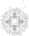
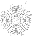
- FIG. 2 It is a figure which shows the structure of the electric power generating apparatus using the linear electric power generating apparatus which concerns on embodiment of this invention. It is the figure which looked at the center yoke and the outer yoke of the linear electric power generating apparatus of embodiment of this invention from the axial direction (vibration direction). It is a figure which divides
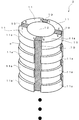
- FIG. 2 It is a perspective view which shows the type B which is another part of the outer yoke of the linear electric power generating apparatus of FIG. 2, FIG. It is a figure which shows the correspondence of a center side protrusion part and an outer side protrusion part. It is a figure which shows state S1 in the positional relationship of a center side protrusion part and an outer side protrusion part. It is a figure which shows the state of the magnetic path which generate
- FIG. 15 is a diagram schematically showing a current generation state in a winding portion in the linear power generator during the passage of time (time t1 to t5) in FIG. It is a figure which shows the state of the magnetic path in the structure and state S1 of the linear electric power generating apparatus of other embodiment. It is a figure which shows the structure of the center yoke of other embodiment.
- the magnetic flux is a bundle of magnetic lines of force
- the magnetic path is a path of magnetic lines of force.
- the expression that a magnetic path is formed by magnetic flux may be replaced when a magnetic path is formed by magnetic lines of force.
- the “linear generator” is simply referred to as “generator”.
- the generator 1 has a center yoke 2, an outer yoke 3, and an output terminal 4 that outputs generated power as external configurations.
- the generator 1 generates power when the center yoke 2 reciprocates (vibrates) in the outer yoke 3.
- the center yoke 2 is configured to reciprocate by an arm 7 connected by a connecting portion 6 to a disk 5 rotated by an engine or the like.
- the outer yoke 3 is fixed to the pedestal portion 8 or the like.
- the axial direction refers to the vertical direction of the center yoke 2 or the outer yoke 3 (the horizontal direction in FIG. 1)
- the circumferential direction refers to a circumferential direction centered on the axial direction. 2 or the direction along the outer periphery of the outer yoke 3.
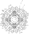
- FIG. 2 shows a view of the center yoke 2 and the outer yoke 3 of the generator 1 as seen from the axial direction (vibration direction).
- FIG. 3 shows the components of the center yoke 2 and the outer yoke 3 of the generator 1 of FIG.
- the state of division shown in FIG. 3 has nothing to do with whether or not division is actually possible, and for convenience of explanation, shows a division method for explanation when it is easier to understand that division is explained.
- the outer yoke 3 is divided into outer yokes 3-1, 3-2, 3-3, and 3-4 in FIG. At this time, the outer yoke 3 is actually integrally formed and may not be divided.
- each member when it is easier to understand that each member is divided, a branch number is assigned to each member (for example, the outer yoke 3) (for example, the outer yoke 3-1, 3-2, 3). -3, 3-4) will be described. Further, if it is easier to understand that the four permanent magnets 10 of the center yoke 2 are divided, the permanent magnets corresponding to the permanent magnets 24-1 to 24-4 of the opposing outer yokes 3-1 to 3-4 are made permanent. These are referred to as magnets 10-1 to 10-4.
- the center yoke 2 of the generator 1 includes a permanent magnet 10 and a center core 11 and is formed in a cylindrical shape as shown in FIGS. That is, the center yoke 2 has a center core 11 made of a soft magnetic material, and has a plurality of rod-shaped permanent magnets 10 that are NS magnetized in the circumferential direction along the axial direction so as to be exposed on a cylindrical outer periphery a.
- the permanent magnets 10 are arranged at equal intervals in the circumferential direction of the center yoke 2. In this embodiment, four permanent magnets 10 are arranged.
- the permanent magnet 10 is arrange
- the center yoke 2 has a plurality of center cores 11 arranged at equal intervals in the circumferential direction when viewed from the axial direction, and each center core 11 is arranged in parallel at equal intervals in the axial direction and along the circumferential direction. And it has the some center side protrusion part 11a which protrudes to radial direction outward from the outer periphery a.
- the center yoke 2 has a hollow portion 12 at the center.
- the hollow portion 12 is provided to reduce the mass of the center yoke 2 for efficient reciprocation. Therefore, the cavity 12 is preferably left as it is, but the cavity 12 may be filled with a light and non-magnetic material such as a light metal such as aluminum or a synthetic resin.
- the outer yoke 3 of the generator 1 has a through hole 20 through which the center yoke 2 passes, as shown in FIG.
- the outer yoke 3 has a cylindrical shape made of a soft magnetic material, and has a plurality of nonmagnetic material portions 21 along the axial direction at equal angles around the axis.
- the nonmagnetic part 21 is a hollow part.
- the outer yoke 3 has a plurality of groove portions 22 respectively extending from the inner periphery b to the nonmagnetic body portion 21.
- the outer yoke 3 has a plurality of outer cores 23 made of a soft magnetic material divided into four parts in this embodiment when viewed from the axial direction, and faces the center side protruding portion 11a of the center yoke 2 in the axial direction. It has a plurality of outer side protrusions 23a that are arranged in parallel at equal intervals and that extend along the circumferential direction and radially inward from the inner circumference b.
- the outer-side protruding portion 23a shown in FIG. 2 is arranged with a half-pitch shift at the intermediate point in the circumferential direction between one groove portion 22 and the groove portion 22 located adjacent to the groove portion 22. That is, as shown in FIG. 3, when the outer yoke 3 is divided into four parts and indicated as outer yokes 3-1, 3-2, 3-3, and 3-4, the outer side protruding portions of the outer yokes 3-1 and 3-3 23a-1 and 23a-3 (for example, type A) and the outer side protrusions 23a-2 and 23a-4 (for example, type B) of the outer yokes 3-2 and 3-4, when viewed in the axial direction, the outer side The position of the protrusion 23a is shifted by a half pitch.
- FIG. 5 is a perspective view of the outer yokes 3-1 and 3-3 that are type A
- FIG. 6 is a perspective view of the outer yokes 3-2 and 3-4 that are type B.
- the outer side protrusions 23a-2 and 23a-4 are positioned not on the outer side but on the inner side, and when both are viewed in the axial direction, the outer side protrusion 23 is shifted by a half pitch. It becomes a state.
- the outer yoke 3 has an outer side protruding portion 23a that is shifted by a half pitch in the axial direction in order to prevent cogging from occurring. Yes.
- a permanent magnet 24 extending in the axial direction is disposed in the groove portion 22.
- the permanent magnet 24 is disposed so as to face the permanent magnet 10 of the center side yoke 2 and is NS magnetized so that the polarities thereof are opposite to each other when viewed in the circumferential direction.
- the outer yoke 3 has a winding part 25 wound around the nonmagnetic body part 21. After forming the winding portion 25, the nonmagnetic body portion 21 may be filled with a nonmagnetic material such as a synthetic resin.
- the center core 11 and the center side protrusion 11a of the center yoke 2 are manufactured by integral molding
- the outer core 23 and the outer side protrusion 23a of the outer yoke 3 are manufactured by integral molding.
- the permanent magnet 10 is bonded to the center core 11 and the permanent magnet 24 is bonded to the outer core 23.
- the permanent magnet 10 and the center core 11 may be formed by insert molding or outsert molding.
- the outer core 23 may be insert-molded or outsert-molded.
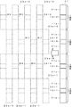
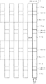
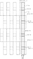
- FIG. 7 shows a state (solid line) in which one of the center side protruding portions 11a of the center yoke 2 is developed in the circumferential direction from the dividing point of the outer yoke 3-1 and the outer yoke 3-2 shown in FIG.
- the outer side protruding portions 23a-1, 23a-2, 23a-3, 23a-4 (broken lines) of the outer yoke 3 facing the portion 11a are schematically shown.
- a white arrow in FIG. 7 indicates a direction in which the center yoke 2 moves in the outer yoke 3.
- the portion where the center side protruding portion 11a can face the outer side protruding portion 23a-2 is defined as the first stage of the center side protruding portion 11a.
- the part where the side protrusion 11a can face the outer side protrusion 23a-3 is the second stage of the center side protrusion 11a
- the part where the center side protrusion 11a can face the outer side protrusion 23a-4 is center side protrusion
- the portion of the center-side protruding portion 11a is divided into the third step of the portion 11a, and the portion where the center-side protruding portion 11a can face the outer-side protruding portion 23a-1 is referred to as the fourth step of the center-side protruding portion 11a. I will explain.
- FIG. 8 shows a state S1 in which the second stage of the center side protruding part 11a faces the outer side protruding part 23a-3 and the fourth stage of the center side protruding part 11a faces the outer side protruding part 23a-1. Show. At this time, the outer side protrusions 23a-2 and 23a-4 are not opposed to the center side protrusion 11a.
- the magnetic flux of the permanent magnets 10-2 and 10-4 of the center yoke 2 is such that the nearby center side protruding portion 11a does not face the outer side protruding portions 23a-2 and 23a-4.
- the protrusion is sucked by the protrusion at an adjacent position where the protrusion is partially opposed. That is, the magnetic fluxes of the permanent magnets 10-2 and 10-4 are attracted to the permanent magnets 24-1 and 24-3 of the outer yoke 3, so that the N pole of the permanent magnet 10-4 ⁇ the S pole of the permanent magnet 24-1 ⁇ permanently.
- the outer side protrusions 23a-2 and 23a-4 are not opposed to the center side protrusion 11a, so that the permanent magnets 24-2 and 24-4 in the outer yokes 3-2 and 3-4
- the magnetic flux does not exit from the outer yokes 3-2 and 3-4, and forms a magnetic path M5 that passes through the winding portion 25-2 and a magnetic path M6 that passes through the winding portion 25-4.
- the magnetic flux density related to these winding portions 25-1 and 25-3 in the state S1 is attracted to the center yoke 2 side. To be minimal.
- the magnetic flux densities of these winding parts 25-2 and 25-4 in the state S1 are the magnetic fluxes of the magnetic paths M5 and M6, respectively. The degree of exit from the outer yokes 3-2 and 3-4 is very small, and each magnetic flux density is maximized.
- the magnetic path M11 corresponds to the magnetic path M2
- the magnetic path M12 corresponds to the magnetic path M3
- the magnetic path M13 corresponds to the magnetic path M4.
- magnetic paths M14, M15, M16, and M17 with a small magnetic flux are formed between the outer yokes 3-2 and 3-4 and the center yoke 2.
- the magnetic paths M14, M15, M16, and M17 have substantially the same strength as the magnetic paths M10, M11, M12, and M13.
- the magnetic flux densities related to these winding portions 25-1 to 25-4 are substantially equal.
- the magnetic flux densities of winding portions 25-1 and 25-3 that were the maximum magnetic flux density in state S1 are reduced, and winding portions 25-2 and 25-4 that were the minimum magnetic flux density in state S1.
- the magnetic flux density increases. That is, the magnetic paths M5 and M6 become magnetic paths M5a and M6a having approximately half the magnetic flux intensity, and are new magnetic paths in the winding portions 25-1 and 25-3, and have the same magnetic flux as the magnetic paths M5a and M6a. Magnetic paths M7a and M8a having a density are formed.
- FIG. 12 shows a state in which the first step of the center side protruding portion 11a faces the outer side protruding portion 23a-2, and the third step of the center side protruding portion 11a faces the outer side protruding portion 23a-4. Is shown. At this time, the outer side protrusions 23a-1 and 23a-3 are not opposed to the center side protrusion 11a.
- the magnetic flux related to the winding portions 25-2 and 25-4 in the state S3 is attracted to the center yoke 2 side. Therefore, it is minimized (not shown in FIG. 13).
- the permanent magnet 24 Since the magnetic flux of -1 and 24-3 leaks very little from the outer yokes 3-1 and 3-3, the magnetic flux density of the winding portions 25-1 and 25-3 is maximized.
- the magnetic path M7a having a weak magnetic flux density becomes a magnetic path M7 having a strong magnetic flux density
- the weak magnetic path M8a becomes a strong magnetic path M8.
- the center yoke 2 moves in the outer yoke 3 in the direction of the white arrow in FIG. 7 (that is, from right to left in FIG. 7), so that the winding portion 25-1
- the magnetic flux density of ⁇ 25-4 repeats between minimum and maximum.
- a current is generated in the winding portions 25-1 to 25-4 in a direction that prevents a change in magnetic flux density.
- the center-side protruding portion 11 that reaches the left end in FIG. 7 moves from the left to the right in FIG. 7, the magnetic flux densities of the winding portions 25-1 to 25-4 are minimum and maximum. Repeat.
- FIG. 14 shows the positional relationship between the center side protrusion 11a of the center yoke 2 and the outer side protrusions 23a-1 to 23a-4 of the outer yoke 3, and the above-described states S1, S2, and S3 are changed from S1 ⁇ S2 ⁇ S3.
- This process is shown along with the elapse of time t1 to t5.
- FIG. 15 shows the state of current generated in the winding portions 25-1 and 25-2 of the generator 1 at the respective times t1 to t5 shown in FIG. Note that the current waveform of the winding section 25-3 is the same as that of the winding section 25-1, and the current waveform of the winding section 25-4 is the same as that of the winding section 25-2. .
- sinusoidal current waveforms are generated in the winding portions 25-1 and 25-2 as shown in FIG. To do.
- time t1 corresponds to state S1 shown in FIG.
- the second stage of the center side protruding portion 11 of the center yoke 2 and the outer side protruding portion 23-3 of the outer yoke 3 face each other, and the magnetic flux density around the winding portion 25-2 is maximized. It will decrease. For this reason, in the winding portion 25-2, a current that generates a line of magnetic force in a direction that prevents the change starts flowing through the wire in a certain direction. If this direction is positive, positive current starts to flow. This point is shown as W11 in FIG.
- time t5 corresponds to state S3 shown in FIG.
- the first stage of the center-side protruding portion 11 of the center yoke 2 and the outer-side protruding portion 23-2 of the outer yoke 3 face each other, and the magnetic flux density around the winding portion 25-2 is minimized. It will increase. For this reason, in the winding portion 25-2, a current that generates a line of magnetic force in a direction that prevents the change starts flowing through the wire in a certain direction. This direction is positive if the above criteria are followed. This point is shown as W12 in FIG. On the other hand, the magnetic flux density around the winding portion 25-1 is maximized and thereafter decreases.
- Time t3 corresponds to state S2 shown in FIG.
- Half of the center side protruding portion 11 of the center yoke 2 and half of the outer side protruding portions 23-1 to 23-4 of the outer yoke 3 face each other.
- Times t2 and t4 are processes of transition from state S1 to S2 and from S2 to S3, respectively. Therefore, at time t2, as shown in FIG. 15, in winding parts 25-1 and 25-2, a substantially intermediate value between the current value (0 amperes) generated in state S1 and the current value generated in state S2, respectively. Current is generated. Further, at time t4, as shown in FIG. 15, in winding parts 25-1 and 25-2, a substantially intermediate value between the current value generated in state S2 and the current value (maximum value) generated in state S3, respectively. Current is generated.
- winding parts 25-1 and 25-2 described above may be made by replacing the winding part 25-1 with the winding part 25-3 and replacing the winding part 25-2 with the winding part 25-4. It is the same.
- the generator 1 generates electric power by outputting the current from the output terminal 4 shown in FIG. 1 by appropriately connecting the winding portions 25-1 to 25-4 to obtain the current in the same direction. can do. Further, if necessary, two currents having different 180 degree cycles may be taken out.
- the attraction force or repulsive force between the center yoke 2 side and the outer yoke 3 side varies depending on the position of the center yoke. is there.
- the facing area between the protruding portions does not change at any time from the time t1 to the time t5.
- the facing area between the center side protruding portion 11a of the center yoke 2 and the outer side protruding portions 23a-1 to 23a-4 of the outer yoke 3 is always constant, and the center The facing area between the side protruding portion 11a and the non-projecting portion of the outer yoke 3 is always constant. For this reason, the attractive force between the center yoke 2 and the outer yoke 3 is always constant.
- the second and fourth stages of the center side protrusion 11a of the center yoke 2 and the outer side protrusions 23a-3 and 23a-1 of the outer yoke 3 are the outer side protrusions. They are opposed to each other with the maximum area of 23a-1 and 23a-3 and attract each other with the maximum suction force.
- the outer side protrusions 23a-2 and 23a-4 of the outer yoke 3 are not opposed to a part of the area of the center side protrusion 11a of the center yoke 2, and the suction force is minimum.
- the strength of the suction force between the center side protrusion 11a of the center yoke 2 and the outer side protrusions 23a-1 to 23a-4 of the outer yoke 3 is the same as that of the center side protrusion 11a of the center yoke 2 and the outer yoke 3 It can be considered that this depends on the total strength of the opposing area portion and the non-opposing area portion between the outer side protruding portions 23a-1 to 23a-4.
- the strength is P1
- the facing area between the second stage of the center side protruding portion 11a of the center yoke 2 and the outer side protruding portion 23a-3 of the outer yoke 3 is Qcm 2
- the suction force is Q ⁇ P1.
- the facing area between the fourth step of the center side protrusion 11a of the center yoke 2 and the outer side protrusion 23a-1 of the outer yoke 3 is also Qcm 2 , and the suction force is Q ⁇ P1.
- the non-facing area between the first step of the center side protrusion 11a of the center yoke 2 and the outer side protrusion 23a-2 of the outer yoke 3 and the third step of the center side protrusion 11a of the center yoke 2 and the outer yoke 3 The non-facing area between the outer projecting portion 23a-4 and the outer-side protruding portion 23a-4 is Qcm 2 , and the suction force per unit of 1 cm 2 of the non-facing portion is P2.
- the first and third quarters of the center-side protrusion 11a of the center yoke 2 in the circumferential direction and the outer-side protrusions 23a-2 and 23a-4 of the outer yoke 3 A quarter of the circumferential direction opposes, and the second and third quarters of the center side protrusion 11a of the center yoke 2 and the outer side protrusions 23a-3 and 23a-1 of the outer yoke 3
- Three quarters of the circumferential direction face each other and attract each other.
- the facing areas between the first and third steps of the center side protruding portion 11a of the center yoke 2 and the outer side protruding portions 23a-2 and 23a-4 of the outer yoke 3 are respectively (1/4) Qcm 2.
- the facing areas between the second and fourth steps of the center side protrusion 11a of the center yoke 2 and the outer side protrusions 23a-3 and 23a-1 of the outer yoke 3 are (3/4) Qcm 2 , respectively. .
- the area of the suction force of the non-opposing portion that is, the portion where the outer side protruding portion 23a-1 to 23a-4 of the outer yoke 3 is not opposed to the center side protruding portion 11a of the center yoke 2 is 2Qcm 2 . Therefore, 2Qcm 2 ⁇ P2. Therefore, the total sum of the attractive forces at time t3 is 2Q (P1 + P2), similar to times t1 and t2.
- the facing areas between the first and third steps of the center side protruding portion 11a of the center yoke 2 and the outer side protruding portions 23a-2 and 23a-4 of the outer yoke 3 are (3/4) Qcm, respectively.
- the opposing areas between the second and fourth steps of the center side protrusion 11a of the center yoke 2 and the outer side protrusions 23a-3 and 23a-1 of the outer yoke 3 are (1/4) respectively.
- Qcm 2 the facing areas between the first and third steps of the center side protruding portion 11a of the center yoke 2 and the outer side protruding portions 23a-2 and 23a-4 of the outer yoke 3 are (3/4) Qcm, respectively.
- the area of the non-facing portion where the center side protruding portion 11a of the center yoke 2 does not face the outer side protruding portions 23a-1 to 23a-4 of the outer yoke 3 is still 2Qcm 2 , and the total suction force is the time t1, Similar to t2 and t3, “2Q (P1 + P2)”.
- the first and third steps of the center side protruding portion 11a of the center yoke 2 and the outer side protruding portions 23a-2 and 23a-4 of the outer yoke 3 face each other.
- the outer side protrusions 23 a-3 and 23 a-1 of the outer yoke 3 are not opposed to the center side protrusion 11 a of the center yoke 2.
- the facing areas between the first and third steps of the center side protruding portion 11a of the center yoke 2 and the outer side protruding portions 23a-2 and 23a-4 of the outer yoke 3 are respectively Qcm 2 .
- the area of the non-opposing portion where the second step and the fourth step of the center side protruding portion 11a of the center yoke 2 do not face the outer side protruding portions 23a-3 and 23a-1 of the outer yoke 3 is also 2Qcm 2 .
- the overall suction force is “2Q (P1 + P2)” at times t1, t2, t3, and t4.
- the total sum of the suction forces at the projecting portions 11a, 23a-1 to 23a-4 between the center yoke 2 and the outer yoke 3 is “2Qcm 2. ⁇ (P1 + P2) ”, which is unchanged.
- the current waveform generated at times t1 to t5 is a current waveform corresponding to a quarter of the sinusoidal current waveforms generated in the winding portions 25-1 to 25-4.
- the current waveform for one quarter period is continuous while changing the positive and negative directions.
- the center side protruding portion 11a of the center yoke 2 and the outer side protruding portions 23a-1 to 23a-4 of the outer yoke 3 are provided at any part of the sinusoidal current waveform generated in the winding portions 25-1 to 25-4. It is self-evident that the suction force between them is always constant. This means that the attractive force between the center yoke 2 and the outer yoke 3 is always constant regardless of the positional relationship between the center yoke 2 and the outer yoke 3. Thus, it can be seen that no cogging occurs in the generator 1.
- the reciprocating motion (vibration) applied to the center yoke 2 from the outside is not reduced by the cogging torque, and most of it is used as torque for power generation. Therefore, highly efficient power generation can be performed.
- the hollow portion 12 and the nonmagnetic body portion 21 may not be hollow but may be configured to embed a nonmagnetic body such as aluminum or a resin material.
- the protrusions 11a and 23a-1 to 23a-4 are integrally formed with the main body of the center yoke 2 and the outer yoke 3, but the protrusions 11a and 23a-1 to 23a-4 are integrally formed. Instead, it may be fixed to each main body by bonding or the like as a separate member.
- the outer side protrusions 23a-1 and 23a-3 and the outer side protrusions 23a-2 and 23a-4 of the outer yoke 3 have been described as being shifted from each other by a half pitch in the axial direction.
- the center side protrusion 11a of the center yoke 2 is shifted by a half pitch in the axial direction with the permanent magnet 10 as a boundary, and the pitch shift of the outer side protrusions 23a-1 to 23a-4 of the outer yoke 3 is eliminated. May be. This also achieves the same operations and effects as the above-described embodiment.
- the axial length of the center yoke 2 shown in FIG. 4 and the axial length of the outer yoke 3 shown in FIGS. 5 and 6 are not limited to this. That is, the minimum length in the axial direction is one stage of either the center side protrusion 11a of the center yoke 2 or the outer side protrusion 23a of the outer yoke 3, and two stages when the other is shifted by a half pitch. If it is a structure, the generator 1 can be comprised.
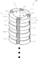
- a plurality of winding portions 25-1 to 25-4 may be provided in parallel in the axial direction. That is, as described above, one set of winding portions 25-1 to 25-4 may be provided for the minimum axial length of the generator 1, and these may be stacked in a plurality of stages. According to this, the power generation amount can be changed according to the number of stages (length).
- the center yoke 2 may be fixed and the outer yoke 3 may reciprocate.
- the center yoke 2 and the outer yoke 3 are preferably soft magnetic materials, but may be simple magnetic materials.
- the groove portion 22 is not formed, but the corresponding portion including the case of such integral formation is referred to as a groove portion.
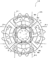
- a generator 1A having no permanent magnet can be formed in the outer yoke 3A. That is, the generator 1 ⁇ / b> A uses the groove 22 after removing the permanent magnet 24 from the outer yoke 3 of the generator 1 as a non-magnetic member. Note that the space after the permanent magnet 24 is removed from the outer yoke 3 may be filled with resin or aluminum which is a non-magnetic material.
- the generator 1A operates in the same manner as the generator 1 according to the above-described embodiment. However, since the outer yoke 3A does not have a permanent magnet, the current waveform is shown by the winding portions 25-1 and 25-2. Inverted from those shown in FIG.
- the state shown in FIG. 16 corresponds to the state S1 shown in FIG.
- the generator 1 in the state S1 shown in FIG. 9 since the generator 1 has the permanent magnet 24-1 in the outer yoke 3-1, the magnetic flux of the permanent magnet 24-1 is reduced by the center yoke 2-1. Therefore, the magnetic flux density passing through the winding portion 25-1 is minimized.
- the permanent magnet 10- is passed through the outer side protruding portion 23a-1 facing the magnetic flux of the permanent magnet 10-1 of the center yoke 2.
- the magnetic path M30 into which the magnetic flux from 1 enters the outer yoke 3-1 side is formed. This maximizes the magnetic flux density around the winding portion 25-1.
- a magnetic path M31 is formed by the magnetic flux from the permanent magnet 10-3.
- magnetic paths M32 and M33 are formed by the magnetic flux from the permanent magnets 10-2 and 10-4.
- the center yoke 2 may be provided with a connecting portion 11b that connects the center core 11 adjacent to the portion into which the permanent magnet 10 enters.
- a connecting portion that connects the outer core 23 may be provided in the groove portion 22 of the outer yoke 3.
- the permanent magnets 10 and 24 are arranged at equal intervals, it is preferable that the magnets are arranged so as to face each other. Therefore, the permanent magnets 10 and 24 are arranged at non-equal intervals, and the permanent magnet 10 and the permanent magnet 24 face each other. You may arrange so that.
- the permanent magnet 10 and the permanent magnet 24 are preferably disposed so as to be completely opposed to each other, but may be disposed slightly shifted from each other.
- the center yoke 2 is an inner type that moves relative to the inside of the outer yoke 3 having the winding portion 25.
- an outer type in which the portion having the winding portion 25 is the inner side may be used.
- the center yoke 2 moves relative to the outside of the outer yoke 3.
- one winding portion 25 is arranged for each nonmagnetic body portion 21, but the number of winding portions 25 may be an appropriate number.
- two winding portions may be provided on one nonmagnetic body portion 21.
Landscapes
- Engineering & Computer Science (AREA)
- Power Engineering (AREA)
- Physics & Mathematics (AREA)
- Chemical & Material Sciences (AREA)
- Combustion & Propulsion (AREA)
- Electromagnetism (AREA)
- Reciprocating, Oscillating Or Vibrating Motors (AREA)
- Permanent Magnet Type Synchronous Machine (AREA)
- Iron Core Of Rotating Electric Machines (AREA)
- Permanent Field Magnets Of Synchronous Machinery (AREA)
Description
(1/4)Qcm2×P1+(1/4)Qcm2×P1+(3/4)Qcm2×P1+(3/4)Qcm2×P1
=(8/4)Qcm2×P1
=2Qcm2×P1
である。一方、非対向部分の吸引力は、同様に計算して、2Qcm2×P2となる。よって時刻t2においても吸引力は、時刻t1と同じように「2Q×P1+2Q×P2=2Q(P1+P2)」となる。
(1/2)Qcm2×P1+(1/2)Qcm2×P1+(1/2)Qcm2×P1+(1/2)Qcm2×P1
=(4/2)Qcm2×P1
=2Qcm2×P1
である。一方、非対向部分、すなわちアウタヨーク3のアウタ側突出部23a-1~23a-4ではない部分とセンタヨーク2のセンタ側突出部11aが対向している部分の吸引力はその面積が2Qcm2となるので、2Qcm2×P2となる。よって、時刻t3においての吸引力の総和は時刻t1,t2と同じように2Q(P1+P2)となる。
(3/4)Qcm2+(3/4)Qcm2+(1/4)Qcm2+(1/4)Qcm2
=(8/4)Qcm2
=2Qcm2
である。このため突出部同士が対向していることによる吸引力は「2Q×P1」となる。一方、センタヨーク2のセンタ側突出部11aがアウタヨーク3のアウタ側突出部23a-1~23a-4と対向していない非対向部分の面積はやはり2Qcm2となり、全体の吸引力は時刻t1,t2,t3と同じく「2Q(P1+P2)」となる。
Qcm2+Qcm2=2Qcm2
である。このため突出部同士が対向していることによる吸引力は「2Q×P1」となる。一方、センタヨーク2のセンタ側突出部11aの2段目および4段目がアウタヨーク3のアウタ側突出部23a-3および23a-1と対向していない非対向部分の面積はやはり2Qcm2となり、全体の吸引力は時刻t1,t2,t3,t4と同じく「2Q(P1+P2)」となる。
上述した実施の形態は、その要旨を逸脱しない限り、様々に変更が可能である。たとえば、空洞部12および非磁性体部21は、中空とせず、非磁性体、たとえばアルミや樹脂材を埋め込む構成としてもよい。また、各突出部11a、23a-1~23a-4はセンタヨーク2およびアウタヨーク3の本体と一体成形されているとして説明したが、各突出部11a、23a-1~23a-4は一体成形とせず、別部材として各本体に接着などで固定するようにしてもよい。
Claims (3)
- 円柱状または円筒状であって、前記円柱状または円筒状の外周には軸方向に長く周方向にNS着磁がなされた棒状の複数の永久磁石を周方向に、かつ隣接する前記永久磁石の対向する磁極が同極となるように配置すると共に周方向に一直線状に配置される複数のセンタ側突出部を有する軟磁性体からなるセンタヨークと、
円筒状または円柱状であって、中心軸を中心として周方向に配置される複数の巻線部と、前記永久磁石に対向する位置に配置される複数の溝部と、前記センタ側突出部に対向して軸方向に半ピッチずれて配置されると共に前記溝部を周方向に挟むアウタ側突出部と、を有する軟磁性体からなるアウタヨークと、
を有する、
ことを特徴とするリニア発電装置。 - 円柱状または円筒状であって、前記円柱状または円筒状の外周には軸方向に長く周方向にNS着磁がなされた棒状の複数の永久磁石を周方向に、かつ隣接する前記永久磁石の対向する磁極が同極となるように配置すると共に周方向に配置される複数のセンタ側突出部を有し、前記永久磁石を挟む前記センタ側突出部の設置位置が隣接するものの間で軸方向に半ピッチずれて配置されるセンタヨークと、
円筒状または円柱状であって、中心軸を中心として周方向に配置される複数の巻線部と、前記永久磁石に対向する位置に配置される複数の溝部と、前記センタ側突出部に対向して周方向に一直線状に配置されると共に前記溝部を周方向に挟むアウタ側突出部と、を有するアウタヨークと、
を有する、
ことを特徴とするリニア発電装置。 - 請求項1または2記載のリニア発電装置であって、
前記溝部には軸方向に沿って配置されると共に対向する前記センタ側ヨークの永久磁石とは反対の極性となるようにNS着磁がなされた永久磁石が配置される、
ことを特徴とするリニア発電装置。
Priority Applications (7)
| Application Number | Priority Date | Filing Date | Title |
|---|---|---|---|
| HK15103068.4A HK1202713B (en) | 2012-02-10 | 2012-12-20 | Linear power generator |
| KR1020147022242A KR102029093B1 (ko) | 2012-02-10 | 2012-12-20 | 리니어 발전 장치 |
| CN201280069526.4A CN104170223B (zh) | 2012-02-10 | 2012-12-20 | 线性发电装置 |
| PL12868050T PL2814148T3 (pl) | 2012-02-10 | 2012-12-20 | Liniowa prądnica |
| EP12868050.1A EP2814148B1 (en) | 2012-02-10 | 2012-12-20 | Linear power generator |
| US14/376,505 US9608505B2 (en) | 2012-02-10 | 2012-12-20 | Linear power generator |
| ES12868050.1T ES2682083T3 (es) | 2012-02-10 | 2012-12-20 | Generador eléctrico lineal |
Applications Claiming Priority (2)
| Application Number | Priority Date | Filing Date | Title |
|---|---|---|---|
| JP2012-027165 | 2012-02-10 | ||
| JP2012027165A JP5809996B2 (ja) | 2012-02-10 | 2012-02-10 | リニア発電装置 |
Publications (1)
| Publication Number | Publication Date |
|---|---|
| WO2013118403A1 true WO2013118403A1 (ja) | 2013-08-15 |
Family
ID=48947190
Family Applications (1)
| Application Number | Title | Priority Date | Filing Date |
|---|---|---|---|
| PCT/JP2012/083020 Ceased WO2013118403A1 (ja) | 2012-02-10 | 2012-12-20 | リニア発電装置 |
Country Status (9)
| Country | Link |
|---|---|
| US (1) | US9608505B2 (ja) |
| EP (1) | EP2814148B1 (ja) |
| JP (1) | JP5809996B2 (ja) |
| KR (1) | KR102029093B1 (ja) |
| CN (1) | CN104170223B (ja) |
| ES (1) | ES2682083T3 (ja) |
| PL (1) | PL2814148T3 (ja) |
| PT (1) | PT2814148T (ja) |
| WO (1) | WO2013118403A1 (ja) |
Families Citing this family (4)
| Publication number | Priority date | Publication date | Assignee | Title |
|---|---|---|---|---|
| US9853529B2 (en) * | 2014-04-29 | 2017-12-26 | Ishwar Ram Singh | Linear induction generator using magnetic repulsion |
| JP6309916B2 (ja) * | 2015-05-14 | 2018-04-11 | 隆逸 小林 | リニア発電装置 |
| US20210367497A1 (en) * | 2017-12-30 | 2021-11-25 | Federico Marquez Lopez | Power generation using motion transformation |
| US20240088771A1 (en) * | 2021-02-15 | 2024-03-14 | Federico Marquez Lopez | Improvement to power generation by motion transformation |
Citations (8)
| Publication number | Priority date | Publication date | Assignee | Title |
|---|---|---|---|---|
| JPH10341564A (ja) * | 1997-06-09 | 1998-12-22 | Ebara Corp | 振動エネルギー変換器 |
| JPH11262234A (ja) | 1998-03-12 | 1999-09-24 | Daido Steel Co Ltd | 振動発電機 |
| JP2000341921A (ja) * | 1999-05-28 | 2000-12-08 | Sanshiro Ogino | ベーシックファクターを用いた発電機能を有する電動機 |
| JP2001327145A (ja) * | 2000-05-17 | 2001-11-22 | Genesis:Kk | ベーシックファクターを用いた回転機 |
| JP2002175913A (ja) * | 2000-12-07 | 2002-06-21 | Genesis:Kk | 磁気吸引部材及びそれを用いた磁気吸引装置 |
| JP2006101695A (ja) | 2005-11-14 | 2006-04-13 | Hitachi Ltd | 永久磁石回転電機および自動車 |
| JP2006523800A (ja) * | 2003-04-14 | 2006-10-19 | スウェディッシュ シーベイスト エナジー アクチボラグ | 電磁的減衰手段を備えた波力発電アセンブリ |
| JP2009189185A (ja) * | 2008-02-07 | 2009-08-20 | Ryuichi Kobayashi | リニア発電装置 |
Family Cites Families (7)
| Publication number | Priority date | Publication date | Assignee | Title |
|---|---|---|---|---|
| US4920292A (en) * | 1986-08-29 | 1990-04-24 | Papst-Motoren Gmbh & Co. Kg | Motor having rotor capable of both stepped rotary and axial shift motions |
| JP3220559B2 (ja) * | 1993-04-27 | 2001-10-22 | オリエンタルモーター株式会社 | リニアパルスモータ |
| JPH0787722A (ja) * | 1993-09-13 | 1995-03-31 | Oriental Motor Co Ltd | リニアモータ |
| JP5082241B2 (ja) * | 2005-12-28 | 2012-11-28 | シンフォニアテクノロジー株式会社 | リニアモータ及びこれに含まれる固定子の製造方法 |
| US7898135B2 (en) * | 2007-03-07 | 2011-03-01 | Qm Power, Inc. | Hybrid permanent magnet motor |
| JP5386925B2 (ja) * | 2008-10-17 | 2014-01-15 | 株式会社安川電機 | 円筒形リニアモータ |
| CN102315746B (zh) * | 2011-04-20 | 2014-07-02 | 华南理工大学 | 混合励磁短磁路变磁阻电机 |
-
2012
- 2012-02-10 JP JP2012027165A patent/JP5809996B2/ja active Active
- 2012-12-20 US US14/376,505 patent/US9608505B2/en not_active Expired - Fee Related
- 2012-12-20 KR KR1020147022242A patent/KR102029093B1/ko not_active Expired - Fee Related
- 2012-12-20 CN CN201280069526.4A patent/CN104170223B/zh not_active Expired - Fee Related
- 2012-12-20 WO PCT/JP2012/083020 patent/WO2013118403A1/ja not_active Ceased
- 2012-12-20 PL PL12868050T patent/PL2814148T3/pl unknown
- 2012-12-20 PT PT128680501T patent/PT2814148T/pt unknown
- 2012-12-20 ES ES12868050.1T patent/ES2682083T3/es active Active
- 2012-12-20 EP EP12868050.1A patent/EP2814148B1/en active Active
Patent Citations (8)
| Publication number | Priority date | Publication date | Assignee | Title |
|---|---|---|---|---|
| JPH10341564A (ja) * | 1997-06-09 | 1998-12-22 | Ebara Corp | 振動エネルギー変換器 |
| JPH11262234A (ja) | 1998-03-12 | 1999-09-24 | Daido Steel Co Ltd | 振動発電機 |
| JP2000341921A (ja) * | 1999-05-28 | 2000-12-08 | Sanshiro Ogino | ベーシックファクターを用いた発電機能を有する電動機 |
| JP2001327145A (ja) * | 2000-05-17 | 2001-11-22 | Genesis:Kk | ベーシックファクターを用いた回転機 |
| JP2002175913A (ja) * | 2000-12-07 | 2002-06-21 | Genesis:Kk | 磁気吸引部材及びそれを用いた磁気吸引装置 |
| JP2006523800A (ja) * | 2003-04-14 | 2006-10-19 | スウェディッシュ シーベイスト エナジー アクチボラグ | 電磁的減衰手段を備えた波力発電アセンブリ |
| JP2006101695A (ja) | 2005-11-14 | 2006-04-13 | Hitachi Ltd | 永久磁石回転電機および自動車 |
| JP2009189185A (ja) * | 2008-02-07 | 2009-08-20 | Ryuichi Kobayashi | リニア発電装置 |
Also Published As
| Publication number | Publication date |
|---|---|
| CN104170223B (zh) | 2017-08-08 |
| US9608505B2 (en) | 2017-03-28 |
| CN104170223A (zh) | 2014-11-26 |
| EP2814148B1 (en) | 2018-05-02 |
| JP2013165573A (ja) | 2013-08-22 |
| KR20140124768A (ko) | 2014-10-27 |
| EP2814148A4 (en) | 2016-01-20 |
| ES2682083T3 (es) | 2018-09-18 |
| US20140375149A1 (en) | 2014-12-25 |
| PT2814148T (pt) | 2018-08-03 |
| EP2814148A1 (en) | 2014-12-17 |
| JP5809996B2 (ja) | 2015-11-11 |
| PL2814148T3 (pl) | 2018-10-31 |
| EP2814148A8 (en) | 2015-02-11 |
| HK1202713A1 (en) | 2015-10-02 |
| KR102029093B1 (ko) | 2019-10-07 |
Similar Documents
| Publication | Publication Date | Title |
|---|---|---|
| WO2018037903A1 (ja) | 同期電動機 | |
| JP2007074776A (ja) | 回転電機 | |
| JP2013515455A (ja) | 変調極機械用の回転子 | |
| US11152825B2 (en) | Electrical machine rotor with eliminated iron bridge | |
| JP5809996B2 (ja) | リニア発電装置 | |
| WO2021039581A1 (ja) | モータ | |
| JP5789182B2 (ja) | 発電機 | |
| US10333362B2 (en) | Internal permanent magnet motor with an outer rotor | |
| JP6001379B2 (ja) | ロータ及びモータ | |
| JP6083640B2 (ja) | 永久磁石埋込型モータ | |
| JP2009273231A (ja) | ハイブリッド励磁モータ | |
| US20170271933A1 (en) | Axial flux motor having modular stators | |
| JP6309916B2 (ja) | リニア発電装置 | |
| JP6260995B2 (ja) | アキシャルギャップ形モータ | |
| JP2013211982A (ja) | ロータ及びモータ | |
| JP5544538B2 (ja) | 磁石埋め込み型円筒リニアモータ | |
| JP2007082300A (ja) | コア及びそれを備える電動機 | |
| JP2013099104A (ja) | ロータ及びモータ | |
| HK1202713B (en) | Linear power generator | |
| JP2014087127A (ja) | 発電機および発電システム | |
| JP6148944B2 (ja) | 発電機および発電システム | |
| JP5991841B2 (ja) | 円筒型リニアモータ | |
| JP6001380B2 (ja) | ロータ及びモータ | |
| JP2016093059A (ja) | 回転機 | |
| JP6561733B2 (ja) | 回転電機 |
Legal Events
| Date | Code | Title | Description |
|---|---|---|---|
| 121 | Ep: the epo has been informed by wipo that ep was designated in this application |
Ref document number: 12868050 Country of ref document: EP Kind code of ref document: A1 |
|
| WWE | Wipo information: entry into national phase |
Ref document number: 2012868050 Country of ref document: EP |
|
| WWE | Wipo information: entry into national phase |
Ref document number: 14376505 Country of ref document: US |
|
| ENP | Entry into the national phase |
Ref document number: 20147022242 Country of ref document: KR Kind code of ref document: A |
|
| NENP | Non-entry into the national phase |
Ref country code: DE |