WO2013118430A2 - Fuel processor - Google Patents
Fuel processor Download PDFInfo
- Publication number
- WO2013118430A2 WO2013118430A2 PCT/JP2013/000218 JP2013000218W WO2013118430A2 WO 2013118430 A2 WO2013118430 A2 WO 2013118430A2 JP 2013000218 W JP2013000218 W JP 2013000218W WO 2013118430 A2 WO2013118430 A2 WO 2013118430A2
- Authority
- WO
- WIPO (PCT)
- Prior art keywords
- partition plate
- mixing
- passage
- hydrogen containing
- containing gas
- Prior art date
- Legal status (The legal status is an assumption and is not a legal conclusion. Google has not performed a legal analysis and makes no representation as to the accuracy of the status listed.)
- Ceased
Links
Images


Classifications
-
- B—PERFORMING OPERATIONS; TRANSPORTING
- B01—PHYSICAL OR CHEMICAL PROCESSES OR APPARATUS IN GENERAL
- B01J—CHEMICAL OR PHYSICAL PROCESSES, e.g. CATALYSIS OR COLLOID CHEMISTRY; THEIR RELEVANT APPARATUS
- B01J8/00—Chemical or physical processes in general, conducted in the presence of fluids and solid particles; Apparatus for such processes
- B01J8/02—Chemical or physical processes in general, conducted in the presence of fluids and solid particles; Apparatus for such processes with stationary particles, e.g. in fixed beds
- B01J8/04—Chemical or physical processes in general, conducted in the presence of fluids and solid particles; Apparatus for such processes with stationary particles, e.g. in fixed beds the fluid passing successively through two or more beds
- B01J8/0492—Feeding reactive fluids
-
- B—PERFORMING OPERATIONS; TRANSPORTING
- B01—PHYSICAL OR CHEMICAL PROCESSES OR APPARATUS IN GENERAL
- B01J—CHEMICAL OR PHYSICAL PROCESSES, e.g. CATALYSIS OR COLLOID CHEMISTRY; THEIR RELEVANT APPARATUS
- B01J8/00—Chemical or physical processes in general, conducted in the presence of fluids and solid particles; Apparatus for such processes
- B01J8/008—Details of the reactor or of the particulate material; Processes to increase or to retard the rate of reaction
-
- B—PERFORMING OPERATIONS; TRANSPORTING
- B01—PHYSICAL OR CHEMICAL PROCESSES OR APPARATUS IN GENERAL
- B01J—CHEMICAL OR PHYSICAL PROCESSES, e.g. CATALYSIS OR COLLOID CHEMISTRY; THEIR RELEVANT APPARATUS
- B01J8/00—Chemical or physical processes in general, conducted in the presence of fluids and solid particles; Apparatus for such processes
- B01J8/02—Chemical or physical processes in general, conducted in the presence of fluids and solid particles; Apparatus for such processes with stationary particles, e.g. in fixed beds
- B01J8/04—Chemical or physical processes in general, conducted in the presence of fluids and solid particles; Apparatus for such processes with stationary particles, e.g. in fixed beds the fluid passing successively through two or more beds
- B01J8/0446—Chemical or physical processes in general, conducted in the presence of fluids and solid particles; Apparatus for such processes with stationary particles, e.g. in fixed beds the fluid passing successively through two or more beds the flow within the beds being predominantly vertical
- B01J8/0461—Chemical or physical processes in general, conducted in the presence of fluids and solid particles; Apparatus for such processes with stationary particles, e.g. in fixed beds the fluid passing successively through two or more beds the flow within the beds being predominantly vertical in two or more cylindrical annular shaped beds
- B01J8/0465—Chemical or physical processes in general, conducted in the presence of fluids and solid particles; Apparatus for such processes with stationary particles, e.g. in fixed beds the fluid passing successively through two or more beds the flow within the beds being predominantly vertical in two or more cylindrical annular shaped beds the beds being concentric
-
- B—PERFORMING OPERATIONS; TRANSPORTING
- B01—PHYSICAL OR CHEMICAL PROCESSES OR APPARATUS IN GENERAL
- B01J—CHEMICAL OR PHYSICAL PROCESSES, e.g. CATALYSIS OR COLLOID CHEMISTRY; THEIR RELEVANT APPARATUS
- B01J8/00—Chemical or physical processes in general, conducted in the presence of fluids and solid particles; Apparatus for such processes
- B01J8/02—Chemical or physical processes in general, conducted in the presence of fluids and solid particles; Apparatus for such processes with stationary particles, e.g. in fixed beds
- B01J8/04—Chemical or physical processes in general, conducted in the presence of fluids and solid particles; Apparatus for such processes with stationary particles, e.g. in fixed beds the fluid passing successively through two or more beds
- B01J8/0446—Chemical or physical processes in general, conducted in the presence of fluids and solid particles; Apparatus for such processes with stationary particles, e.g. in fixed beds the fluid passing successively through two or more beds the flow within the beds being predominantly vertical
- B01J8/0461—Chemical or physical processes in general, conducted in the presence of fluids and solid particles; Apparatus for such processes with stationary particles, e.g. in fixed beds the fluid passing successively through two or more beds the flow within the beds being predominantly vertical in two or more cylindrical annular shaped beds
- B01J8/0469—Chemical or physical processes in general, conducted in the presence of fluids and solid particles; Apparatus for such processes with stationary particles, e.g. in fixed beds the fluid passing successively through two or more beds the flow within the beds being predominantly vertical in two or more cylindrical annular shaped beds the beds being superimposed one above the other
-
- C—CHEMISTRY; METALLURGY
- C01—INORGANIC CHEMISTRY
- C01B—NON-METALLIC ELEMENTS; COMPOUNDS THEREOF; METALLOIDS OR COMPOUNDS THEREOF NOT COVERED BY SUBCLASS C01C
- C01B3/00—Hydrogen; Gaseous mixtures containing hydrogen; Separation of hydrogen from mixtures containing it; Purification of hydrogen; Reversible storage of hydrogen
- C01B3/02—Production of hydrogen; Production of gaseous mixtures containing hydrogen
- C01B3/32—Production of hydrogen; Production of gaseous mixtures containing hydrogen by reaction of gaseous or liquid organic compounds with gasifying agents, e.g. water, carbon dioxide or air
- C01B3/34—Production of hydrogen; Production of gaseous mixtures containing hydrogen by reaction of gaseous or liquid organic compounds with gasifying agents, e.g. water, carbon dioxide or air by reaction of hydrocarbons with gasifying agents
- C01B3/38—Production of hydrogen; Production of gaseous mixtures containing hydrogen by reaction of gaseous or liquid organic compounds with gasifying agents, e.g. water, carbon dioxide or air by reaction of hydrocarbons with gasifying agents using catalysts
-
- C—CHEMISTRY; METALLURGY
- C01—INORGANIC CHEMISTRY
- C01B—NON-METALLIC ELEMENTS; COMPOUNDS THEREOF; METALLOIDS OR COMPOUNDS THEREOF NOT COVERED BY SUBCLASS C01C
- C01B3/00—Hydrogen; Gaseous mixtures containing hydrogen; Separation of hydrogen from mixtures containing it; Purification of hydrogen; Reversible storage of hydrogen
- C01B3/50—Separation of hydrogen or hydrogen-containing gases from gaseous mixtures, e.g. purification
- C01B3/56—Separation of hydrogen or hydrogen-containing gases from gaseous mixtures, e.g. purification by contacting with solids; Regeneration of used solids
- C01B3/58—Separation of hydrogen or hydrogen-containing gases from gaseous mixtures, e.g. purification by contacting with solids; Regeneration of used solids including a catalytic reaction
- C01B3/583—Separation of hydrogen or hydrogen-containing gases from gaseous mixtures, e.g. purification by contacting with solids; Regeneration of used solids including a catalytic reaction the reaction being the selective oxidation of carbon monoxide
-
- B—PERFORMING OPERATIONS; TRANSPORTING
- B01—PHYSICAL OR CHEMICAL PROCESSES OR APPARATUS IN GENERAL
- B01J—CHEMICAL OR PHYSICAL PROCESSES, e.g. CATALYSIS OR COLLOID CHEMISTRY; THEIR RELEVANT APPARATUS
- B01J2208/00—Processes carried out in the presence of solid particles; Reactors therefor
- B01J2208/00008—Controlling the process
- B01J2208/00017—Controlling the temperature
- B01J2208/00504—Controlling the temperature by means of a burner
-
- B—PERFORMING OPERATIONS; TRANSPORTING
- B01—PHYSICAL OR CHEMICAL PROCESSES OR APPARATUS IN GENERAL
- B01J—CHEMICAL OR PHYSICAL PROCESSES, e.g. CATALYSIS OR COLLOID CHEMISTRY; THEIR RELEVANT APPARATUS
- B01J2208/00—Processes carried out in the presence of solid particles; Reactors therefor
- B01J2208/00008—Controlling the process
- B01J2208/00017—Controlling the temperature
- B01J2208/0053—Controlling multiple zones along the direction of flow, e.g. pre-heating and after-cooling
-
- B—PERFORMING OPERATIONS; TRANSPORTING
- B01—PHYSICAL OR CHEMICAL PROCESSES OR APPARATUS IN GENERAL
- B01J—CHEMICAL OR PHYSICAL PROCESSES, e.g. CATALYSIS OR COLLOID CHEMISTRY; THEIR RELEVANT APPARATUS
- B01J2208/00—Processes carried out in the presence of solid particles; Reactors therefor
- B01J2208/00796—Details of the reactor or of the particulate material
- B01J2208/00823—Mixing elements
- B01J2208/00831—Stationary elements
- B01J2208/00849—Stationary elements outside the bed, e.g. baffles
-
- B—PERFORMING OPERATIONS; TRANSPORTING
- B01—PHYSICAL OR CHEMICAL PROCESSES OR APPARATUS IN GENERAL
- B01J—CHEMICAL OR PHYSICAL PROCESSES, e.g. CATALYSIS OR COLLOID CHEMISTRY; THEIR RELEVANT APPARATUS
- B01J2208/00—Processes carried out in the presence of solid particles; Reactors therefor
- B01J2208/00796—Details of the reactor or of the particulate material
- B01J2208/00893—Feeding means for the reactants
- B01J2208/0092—Perforated plates
-
- B—PERFORMING OPERATIONS; TRANSPORTING
- B01—PHYSICAL OR CHEMICAL PROCESSES OR APPARATUS IN GENERAL
- B01J—CHEMICAL OR PHYSICAL PROCESSES, e.g. CATALYSIS OR COLLOID CHEMISTRY; THEIR RELEVANT APPARATUS
- B01J2208/00—Processes carried out in the presence of solid particles; Reactors therefor
- B01J2208/00796—Details of the reactor or of the particulate material
- B01J2208/00893—Feeding means for the reactants
- B01J2208/00929—Provided with baffles
-
- B—PERFORMING OPERATIONS; TRANSPORTING
- B01—PHYSICAL OR CHEMICAL PROCESSES OR APPARATUS IN GENERAL
- B01J—CHEMICAL OR PHYSICAL PROCESSES, e.g. CATALYSIS OR COLLOID CHEMISTRY; THEIR RELEVANT APPARATUS
- B01J2208/00—Processes carried out in the presence of solid particles; Reactors therefor
- B01J2208/00796—Details of the reactor or of the particulate material
- B01J2208/00938—Flow distribution elements
-
- B—PERFORMING OPERATIONS; TRANSPORTING
- B01—PHYSICAL OR CHEMICAL PROCESSES OR APPARATUS IN GENERAL
- B01J—CHEMICAL OR PHYSICAL PROCESSES, e.g. CATALYSIS OR COLLOID CHEMISTRY; THEIR RELEVANT APPARATUS
- B01J2208/00—Processes carried out in the presence of solid particles; Reactors therefor
- B01J2208/02—Processes carried out in the presence of solid particles; Reactors therefor with stationary particles
- B01J2208/023—Details
- B01J2208/024—Particulate material
- B01J2208/025—Two or more types of catalyst
-
- C—CHEMISTRY; METALLURGY
- C01—INORGANIC CHEMISTRY
- C01B—NON-METALLIC ELEMENTS; COMPOUNDS THEREOF; METALLOIDS OR COMPOUNDS THEREOF NOT COVERED BY SUBCLASS C01C
- C01B2203/00—Integrated processes for the production of hydrogen or synthesis gas
- C01B2203/02—Processes for making hydrogen or synthesis gas
- C01B2203/0205—Processes for making hydrogen or synthesis gas containing a reforming step
-
- C—CHEMISTRY; METALLURGY
- C01—INORGANIC CHEMISTRY
- C01B—NON-METALLIC ELEMENTS; COMPOUNDS THEREOF; METALLOIDS OR COMPOUNDS THEREOF NOT COVERED BY SUBCLASS C01C
- C01B2203/00—Integrated processes for the production of hydrogen or synthesis gas
- C01B2203/04—Integrated processes for the production of hydrogen or synthesis gas containing a purification step for the hydrogen or the synthesis gas
- C01B2203/0435—Catalytic purification
- C01B2203/044—Selective oxidation of carbon monoxide
-
- C—CHEMISTRY; METALLURGY
- C01—INORGANIC CHEMISTRY
- C01B—NON-METALLIC ELEMENTS; COMPOUNDS THEREOF; METALLOIDS OR COMPOUNDS THEREOF NOT COVERED BY SUBCLASS C01C
- C01B2203/00—Integrated processes for the production of hydrogen or synthesis gas
- C01B2203/04—Integrated processes for the production of hydrogen or synthesis gas containing a purification step for the hydrogen or the synthesis gas
- C01B2203/0465—Composition of the impurity
- C01B2203/047—Composition of the impurity the impurity being carbon monoxide
-
- C—CHEMISTRY; METALLURGY
- C01—INORGANIC CHEMISTRY
- C01B—NON-METALLIC ELEMENTS; COMPOUNDS THEREOF; METALLOIDS OR COMPOUNDS THEREOF NOT COVERED BY SUBCLASS C01C
- C01B2203/00—Integrated processes for the production of hydrogen or synthesis gas
- C01B2203/08—Methods of heating or cooling
- C01B2203/0805—Methods of heating the process for making hydrogen or synthesis gas
- C01B2203/0811—Methods of heating the process for making hydrogen or synthesis gas by combustion of fuel
- C01B2203/0816—Heating by flames
Definitions
- the present invention relates to a fuel processor that steam reforms hydrocarbon source gas such as town gas and LPG to manufacture hydrogen-rich reformed gas, and is used for manufacturing fuel gas for a fuel cell power generator and so on.
- a conventional fuel processor is entirely cylindrical.
- a known fuel processor includes a heater containing a burner at the center, a reformer filled with a reforming catalyst around the heater, a converter filled with a carbon monoxide (CO) converter catalyst, and a CO remover filled with a carbon monoxide (CO) removal catalyst. These components re arranged in the axial direction (for example, see Patent Literature 1).
- source gas and reformed water are supplied into a gas passage acting as an evaporator around the heater, and then source gas and steam are supplied into the reformer. Moreover, hydrogen containing gas fed from the reformer is sequentially supplied to the converter provided around the gas passage, and the CO remover. Thus, reformed gas is produced.
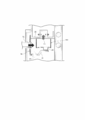
- FIG. 22 illustrates the fuel processor described in Patent Literature 1.
- a fuel processor 1 is entirely cylindrical and is insulated by a heat insulating material 1a covering the outer surface of the fuel processor 1.
- a heating unit 5 is provided at the center of the fuel processor 1.
- the heating unit 5 includes a heat chamber 3 containing a burner 2, and an exhaust passage 4 provided around the heat chamber 3.
- An outlet port 4a of the exhaust passage 4 is opened to the outside.
- a first gas passage 6 acting as an evaporator is disposed around the outlet port 4a of the exhaust passage 4 of the heating unit 5.
- a reforming part 8 filled with a reforming catalyst 7 is disposed around the exhaust passage 4.
- a second gas passage 9 for passing hydrogen containing gas 73 from the reforming part 8 to the outer surface of the first gas passage 6 is disposed around the reforming part 8.
- a converting part 11 filled with a CO converter catalyst 10 is disposed near the reforming part 8 provided around the first gas passage 6.
- a CO removing part 14 filled with a CO removal catalyst 13 is disposed away from the reforming part 8 on the outer surface of the first gas passage 6 and outside a third gas passage 12 in the radial direction.
- Source gas 70 supplied to an inlet 6a of the first gas passage 6 is mixed at the inlet 6a of the first gas passage 6 with reformed water 72 supplied through a heating coil 15 wound around the converting part 11 and the CO removing part 14.
- the source gas 70 and the reformed water 72 are heated through the first gas passage 6 acting as an evaporator.
- the high-temperature source gas 70 and steam are supplied to the reforming part 8, and then the source gas 70 is steam reformed by the action of the reforming catalyst 7 into the hydrogen containing gas 73.
- the hydrogen containing gas 73 fed from the reforming part 8 is supplied to the converting part 11 through the second gas passage 9, and then carbon monoxide (CO) in gas is reduced by the action of the CO converter catalyst 10.
- the hydrogen containing gas 73 fed from the converting part 11 is mixed with air 71, which is introduced from an air inlet port 16a, in the air mixing space of a mixing part 16 provided between the converting part 11 and the third gas passage 12.
- the hydrogen containing gas 73 mixed with the air 71 is supplied to the CO removing part 14 through the third gas passage 12, CO is removed by the action of the CO removal catalyst 13, and then the hydrogen containing gas 73 is fed from a hydrogen containing gas outlet port 17.
- the fuel processor 1 shown in FIG. 22 has the third gas passage 12 interposed between the CO removing part 14 and the first gas passage 6 at a high temperature.
- a temperature downstream of the converting part 11 can be kept at an optimum temperature for a reaction (e.g., 200 degrees C); meanwhile, the inlet temperature of the CO removing part 14 can be kept at a temperature (e.g., 150 degrees C) where an oxidation reaction is not excessively accelerated.
- the converting part 11 and the CO removing part 14 can be advantageously kept at a suitable temperature.
- Carbon monoxide CO is removed from the CO removal catalyst 13 by the following chemical reaction:
- the hydrogen containing gas 73 containing carbon monoxide CO and the air 71 containing oxygen O 2 need to be sufficiently mixed.
- the chemical reaction is not accelerated, precluding sufficient removal of CO.
- the air mixing space and the air inlet port 16a of the mixing part 16 are provided with complicated shapes or the third gas passage 12 is extended.
- such configurations for improving mixing are likely to increase a pressure loss.
- such shapes lead to a larger volume of the air mixing space of the mixing part 16, thereby increasing heat radiation with lower efficiency and higher manufacturing cost.
- a fuel processor in Patent Literature 2 proposes a shape of a mixing part for solving the problem.
- FIG. 23 illustrates the mixing part of the fuel processor described in Patent Literature 2.
- a mixing passage 100 includes a pipe-shaped gas supply region 110, a gas diffusion region 120, gas supply ports 111 that are holes on the side of the gas supply region 110, and an air inlet port 101 at the starting end of the gas supply region 110.
- Air flowing from the air inlet port 101 and hydrogen containing gas flowing from the gas supply ports 111 are mixed in the gas supply region 110 and the gas diffusion region 120.
- the gas diffusion region 120 includes a region for diffusing the gas and air so as to further accelerate the mixing. Thus, the mixing can be efficiently completed.
- gas is supplied through the gas supply ports into the gas supply region 110 for an air flow, suppressing a flow rate upstream of the passage. Hence, a pressure loss can be smaller than that of a jet of hydrogen containing gas.
- Patent Literature 3 and Patent Literature 4 describe similar fuel processors.
- the mixing passage in FIG. 23 has a complicated shape and thus requires working for bending the pipe of the passage into an arc, working for forming the many holes, working for bending the passage to a right angle, and so on, which may increase the cost of components.
- the components are desirably fixed to each other by, for example, continuous welding.
- continuous welding In order to prevent leakage and damage during a long operation, the components are desirably fixed to each other by, for example, continuous welding.
- complicated shapes are hard to automatically weld and thus need to be manually welded, resulting in lower yields with a large number of manufacturing steps.
- the flow rate of the hydrogen containing gas 73 increases.
- the catalysts cannot be sufficiently mixed in the mixing passage.
- CO contained in the hydrogen containing gas 73 cannot be sufficiently reduced.
- a CO concentration of 0.5% or less cannot be obtained that is set as an upper limit during the design of the CO removing part 14.
- oxygen O 2 cannot be sufficiently mixed with increased CO.
- the hydrogen containing gas 73 containing a high concentration of CO (at least 0.5%) is supplied to a power generation stack and the catalyst in the stack is poisoned (catalyst poisoning) so as to reduce power generation capacity, leading to system shutdown.
- An object of the present invention is to provide a fuel processor that is inexpensively configured with a small number of manufacturing steps, obtains a mixing passage with a sufficient distance without increasing a pressure loss, and includes a mixing part with high mixing capability.
- a fuel processor includes: a reforming part that is provided around a heating unit including a burner and generates hydrogen containing gas composed of carbon monoxide and water; a converting part that is provided around the heater and generates hydrogen containing gas composed of low-concentration carbon monoxide by reacting carbon monoxide and water in the hydrogen containing gas generated in the reforming part; a mixing part that is provided around the heater and mixes air supplied from an air inlet port and the hydrogen containing gas generated in the converting part; and a CO removing part that reacts oxygen, carbon monoxide in the gas supplied from the mixing part, and a CO removal catalyst to generate hydrogen containing gas hardly containing carbon monoxide, and the fuel processor further includes a partition plate that divides the passage of the mixing part, the partition plate partially including a tilted portion.
- a fuel processor includes: a reforming part that is provided around a heating unit including a burner and generates hydrogen containing gas composed of carbon monoxide and water; a converting part that is provided around the heater and generates hydrogen containing gas composed of low-concentration carbon monoxide by reacting carbon monoxide and water in the hydrogen containing gas generated in the reforming part; a mixing part that is provided around the heater and mixes air supplied from an air inlet port and the hydrogen containing gas generated in the converting part; and a CO removing part that reacts oxygen, carbon monoxide in the gas supplied from the mixing part, and a CO removal catalyst to generate hydrogen containing gas hardly containing carbon monoxide, and the fuel processor further includes a partition plate that divides the passage of the mixing part at least into first and second passages, the partition plate including an inlet of mixed gas from the first passage to the second passage, the inlet being located at or substantially at 180 degrees in the circumferential direction with respect to the inlet position of the mixed gas in the first passage.
- a fuel processor includes: a reforming part that is provided around a heating unit including a burner and generates hydrogen containing gas composed of carbon monoxide and water; a converting part that is provided around the heater and generates hydrogen containing gas composed of low-concentration carbon monoxide by reacting carbon monoxide and water in the hydrogen containing gas generated in the reforming part; a mixing part that is provided around the heater and mixes air supplied from an air inlet port and the hydrogen containing gas generated in the converting part; a CO removing part that reacts oxygen, carbon monoxide in the gas supplied from the mixing part, and a CO removal catalyst to generate hydrogen containing gas hardly containing carbon monoxide; and a partition plate that divides the passage of the mixing part at least into first and second passages, wherein the mixing part is formed between a first partition near the converting part and a second partition near the CO removing part, the partition plate has a groove extended around the heater in a circumferential direction, and the groove has a bottom that is in contact with
- the air mixing space of the mixing part is divided into the outer passage and the inner passage by the partition plate.
- the configuration is inexpensive and requires only a small number of manufacturing steps, and a mixing passage can be obtained with a sufficient distance without increasing a pressure loss, thereby exhibiting high mixing capability.
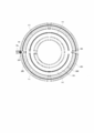
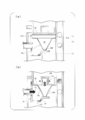
- FIG. 1 is a longitudinal section illustrating the mixing part of a fuel processor according to a first embodiment.
- FIG. 2 is a cross-sectional view taken along line A-A of FIG. 1.
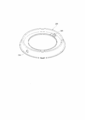
- FIG. 3 is an external perspective view illustrating a partition plate according to the first embodiment.
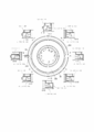
- FIG. 4 shows the analysis results of the fuel processor according to the first embodiment.
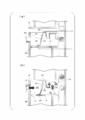
- FIG. 5 is a cross-sectional view illustrating the step of assembling the mixing part according to the first embodiment.
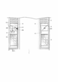
- FIG. 6 is a longitudinal section illustrating a mixing part in a fuel processor according to a second embodiment.
- FIG. 7 is a cross-sectional view taken along line J-J of FIG. 6.
- FIG. 8 is a longitudinal section illustrating a mixing part in a fuel processor according to a third embodiment.
- FIG. 9 is a cross-sectional view taken along line K-K of FIG. 8.
- FIG. 10 is an external perspective view illustrating a partition plate according to the third embodiment.
- FIG. 11 is a cross-sectional view illustrating the step of assembling the mixing part according to the third embodiment.
- FIG. 12 is a longitudinal section illustrating a mixing part in a fuel processor according to a fourth embodiment.
- FIG. 13 is a cross-sectional view illustrating the step of assembling the mixing part according to the fourth embodiment.
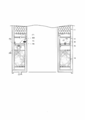
- FIG. 14 is a longitudinal section illustrating a mixing part in a fuel processor according to a fifth embodiment.
- FIG. 15 is a cross-sectional view illustrating the step of assembling the mixing part according to the fifth embodiment.
- FIG. 16 is a longitudinal section illustrating a mixing part in a fuel processor according to a sixth embodiment.
- FIG. 17 is a plan view illustrating a partition plate according to the sixth embodiment.
- FIG. 18 is a longitudinal section illustrating a mixing part in a fuel processor according to a seventh embodiment.
- FIG. 19 is a cross-sectional view illustrating the step of assembling the mixing part according to the seventh embodiment.
- FIG. 20 is a plan view illustrating a partition plate according to an eighth embodiment.
- FIG. 21 is a plan view illustrating another example of the partition plate according to the third embodiment.
- FIG. 22 is a longitudinal section illustrating a fuel processor of a conventional example described in Patent Literature 1.
- FIG. 23 is a plan view illustrating a mixing part in a fuel processor described in Patent Literature 2.
- FIGS. 1 to 5 illustrate a first embodiment of the present invention.
- FIG. 1 is a longitudinal section of a fuel processor.
- FIG. 2 is a cross-sectional view taken along the line A-A of FIG. 1. The cross-sectional view basically illustrates only a cross section. Only a gas inlet port 203 is illustrated as a projected shape for explanation.
- FIGS. 1 and 2 components having the same functions as the fuel processor in the conventional example in FIGS. 22 and 23 are indicated by the same reference numerals, and the explanation thereof is omitted.
- a hollow arrow F1 indicates a flow of reformed hydrogen containing gas
- a black arrow F2 indicates an air flow
- a cross hatching arrow F3 indicates a flow of mixed gas.
- the air mixing space of the mixing part 16 provided between the converting part 11 and the third gas passage 12 does not contain any partitions, whereas in the first embodiment, the air mixing space of a mixing part 16 is divided into an outer passage 201 and an inner passage 202 by a partition plate 200.
- the mixed gas further travels halfway through the inner passage 202, passes through a gas outlet 205, and then flows into a third gas passage 12.
- the gas is mixed through the outer passage 201 and the inner passage 202 and evenly flows into the third gas passage 12. After that, heat is exchanged with source gas containing water passing through a first gas passage 6, and then the gas is cooled (e.g., from 250 degrees C to 150 degrees C).
- the gas then passes through a third gas passage outlet port 12a and flows into a CO removing part 14, so that CO is substantially completely removed(for example, to 10 ppm or less).
- FIG. 3 is a perspective view illustrating a shape of the partition plate 200 in consideration of actual fabrication.
- the partition plate 200 can be produced as a single component only by press working.
- the size of the side hole 204 is set at 6 mm (about 28 mm 2 ) in diameter by optimization, which will be described later.
- the size of the side hole 204 can be optionally set in a working range.
- the gas outlet 205 is a cut and raised hole that is formed to circulate mixed gas in the third gas passage 12 so as to equalize flow velocities and flow rates in a circumferential direction before the gas reaches the third gas passage outlet port 12a and improve the use efficiency of a CO removal catalyst 13.
- the open area of the gas outlet 205 is about 30 mm 2 through optimization, which will be described later.
- the sizes of the side hole 204 and the gas outlet 205 considerably affect a pressure loss but less affect mixing.
- the partition plate 200 is easily fabricated and the bore size is determined so as to keep a permissible pressure loss. A pressure loss is effectively reduced by increasing the sizes of the side hole 204 and the gas outlet 205.
- the partition plate 200 is in contact with multiple points of a partition constituting the air mixing space of the mixing part 16. Specifically, as illustrated in FIG. 1, the partition plate 200 is in contact with three points: a first contact portion 206 on a bottom plate 21 serving as a first partition near the converting part 11; a second contact portion 207 on a top plate 22 serving as a second partition near the CO removing part 14; and an inner contact portion 208.
- a gap on these portions unmixed gas may leak rearward in the passage, resulting in inefficient removal of CO. Such a gap is reliably prevented by fixing these contact portions by welding or brazing.
- first and second contact portions 206 and 207 only have a small clearance relative to the cross-sectional area of the passage (e.g., 1% or less), most of gas passes through the mixing passage due to a pressure difference. Thus, leakage hardly affects the overall mixed gas, allowing sufficient mixing of the gas through the third gas passage 12. Hence, the first and second contact portions 206 and 207 are not fixed by welding or brazing.
- the partition plate 200 is elastically deformed onto components constituting the air mixing space of the mixing part 16, thereby fully satisfying the function of the mixing passage.
- FIG. 5 illustrates the step of attaching the partition plate 200 into the mixing part 16.
- FIG. 5(a) shows the partition plate 200 having been inserted into the outer periphery of a heating unit 5 before the CO removing part 14 is fixed.
- the inner contact portion 208 of the partition plate 200 is in contact with the outer surface of the heating unit 5, and the first contact portion 206 of the partition plate 200 is in contact with the bottom plate 21 of the mixing part 16.
- the second contact portion 207 of the partition plate 200 is pressed.
- the partition plate 200 is further pressed in a direction that reduces a clearance between the first contact portion 206 of the partition plate 200 and the bottom plate 21 of the mixing part 16 and a clearance between the second contact portion 207 of the partition plate 200 and the top plate 22 of the mixing part 16.
- L1 is a distance between the first contact portion 206 and the center of the heating unit 5
- L2 is a distance between the second contact portion 207 and the center of the heating unit 5.
- An outer tilted portion 23a is integrally formed between the first contact portion 206 and the second contact portion 207 of the partition plate 200. Since an inner tilted portion 23b is formed inside the second contact portion 207, the outer tilted portion 23a is elastically deformed from a virtual line position to a solid line position. The inner tilted portion 23b is also slightly elastically deformed.
- the elastic deformation of the outer tilted portion 23a and the inner tilted portion 23b eliminates a difference in dimension between the height of the partition plate 200 and the inner height of the mixing part 16, and acts in a direction that reduces a clearance between the first contact portion 206 of the partition plate 200 and the bottom plate 21 of the mixing part 16 and a clearance between the second contact portion 207 of the partition plate 200 and the top plate 22 of the mixing part 16.
- the top plate 22 of the mixing part 16 is joined and fixed to the converting part 11 by welding, brazing, and so on.
- mixing capability equal to or higher than that of the configuration of FIG. 23 was obtained only by the partition plate 200 fabricated by press working, without additional fixation by welding and so on. Hence, the cost of components and the manufacturing steps were considerably reduced.
- elasticity was obtained by setting the thickness of the partition plate 200 at 0.3 mm relative to the structure having a thickness of 0.8 mm to 1.0 mm.
- the partition plate 200 is desirably made of a spring material, stainless was used instead as in the structure in consideration of heat resistance and cost.
- the partition plate 200 is fixed while being compressed by 0.1 mm to 0.3 mm in the axial direction, so that the first contact portion 206 is in contact with the outer surface of the converting part 11 and the second contact portion 207 is in contact with the outer surface of the CO removing part 14.
- the amount of compression may be, for example, about 1 mm.
- the inner contact portion 208 is radially fit to the first gas passage with a clearance of 0 mm to 0.4 mm.
- the contact portion is desirably brought into contact with the first gas passage by tube expansion or caulking, but fitting alone provides sufficient resistance to leakage.
- the fitting configuration can reduce a stress applied to the structure as compared with fixation by welding and so on, even in the case where the fuel processor is repeatedly started and stopped to obtain heat shrinkage by heating and cooling. Thus, it is expected to prevent problems caused by fatigue breakdown in an extended period of use.
- the mixing passage of this configuration has a length of about 380 mm.
- the mixing distance is at least two times larger than that of the configuration of the fuel processor in FIG. 23, that is, about 180 mm with an identical output and a substantially equal product outside diameter.
- the effect of the first embodiment was examined using analysis results in FIG. 4.
- a three-dimensional model was used for the analysis.
- General-purpose thermal-liquid analysis software, "ANSYS FLUENT 12.1" of ANSYS, Inc. was used.
- the flow rate of air was 7.67 * 10 -6 kg/s
- the air temperature was 25 degrees C
- the flow rate of hydrogen containing gas was 1.69 * 10 -4 kg/s
- the temperature of the hydrogen containing gas was 200 degrees C.
- the hydrogen containing gas contained 3.1% methane, 21.2% steam, 15.2% carbon dioxide, 0.2% carbon monoxide, and 60.3% hydrogen.
- Mole ratios O 2 /CO of a concentration of oxygen O 2 to a concentration of carbon monoxide CO in mixed gas in the outer passage 201 and the inner passage 202 were measured at cross-sectional positions B-B, C-C, D-D, E-E, F-F, G-G, H-H, and I-I in the air mixing space of the mixing part 16 in FIG. 4.
- H is at least 3.30 and (L) is 1.50 or less.
- a mole ratio O 2 /CO of a concentration of oxygen O 2 to a concentration of carbon monoxide CO was measured in a flow of mixed gas. Since O 2 is contained in the air and CO is contained in hydrogen containing gas, small variations in O 2 /CO indicate sufficient mixing. In requirements specifications determined by the characteristics of the CO removal catalyst, ratios O 2 /CO in mixed gas are within the range of 1.8 to 3.0.
- a pressure loss is suppressed to 500 Pa or less.
- O 2 /CO values substantially converge in the outer passage 201 and stay within the range of 1.86 to 2.13 in the side hole 204. In other words, mixing is fully completed at this point. After that, the gas is further mixed through the inner passage 202 where O 2 /CO values converge within the range of 1.95 to 2.04 and hardly change. Thus, it was confirmed that this configuration has sufficient mixing capability and high robustness with a sufficient margin.
- the side hole 204 and the gas outlet 205 were small in an initial design, and thus a pressure loss considerably exceeded a permissible value.
- the side hole 204 and the gas outlet 205 were then sequentially increased in size, which hardly affected mixing and smoothly reduced the pressure loss. Finally, the current size was set in view of balance with workability.
- a fuel processor including the mixing part 16 of the first embodiment was actually fabricated to conduct an operation test.
- a CO concentration in produced hydrogen containing gas was 10 ppm or less, which means that CO was normally reduced.
- an abnormal CO concentration or an abnormal pressure loss was not found.
- FIGS. 6 and 7 illustrate a second embodiment according to the present invention.
- the mixing passage is divided into the outer passage 201 and the inner passage 202, whereas in the second embodiment, a mixing passage is divided into three or more passages (four passages in the present embodiment).
- FIG. 6 illustrates a longitudinal section of the configuration of a principle part.
- FIG. 7 is a cross-sectional view taken along line J-J.
- the cross-sectional view basically illustrates only a cross section.
- a hollow arrow F1 indicates a flow of reformed hydrogen containing gas
- a black arrow F2 indicates an air flow
- a cross hatching arrow F3 indicates a flow of mixed gas.
- the mixed gas further travels halfway through the first intermediate passage 209, passes through a second side hole 204a, a second intermediate passage 210, and a third side hole 204b, and then flows into an inner passage 202.
- the subsequent flow is identical to that of the first embodiment.
- the mixing passage of this configuration has a length of about 750 mm.
- the mixing distance is at least four times larger than that of the configuration of the fuel processor in FIG. 23, that is, about 180 mm with an identical output and a substantially equal product outside diameter. Thus, higher robustness can be obtained.
- the heating unit 5 has an outside diameter of 79 mm and the fuel processor has an outside diameter of 144 mm in view of a catalyst amount determined by an output.
- the product outside diameter may be reduced by the development of small-size and low-output models and a catalyst having a honeycomb configuration. Also in this case, a mixing distance hardly changes, and thus the volume of the air mixing space of the mixing part 16 may relatively increase. Also in this case, this configuration can achieve sufficient mixing capability without increasing the air mixing space even if the outside diameter decreases.
- a partition plate 200 has tilted portions in the second embodiment. Specifically, tilted portions 23a, 23a2, 23a3, and 23b in FIG. 6 are provided. The tilted portions allow the elastic deformation of the outer tilted portion 23a, the inner tilted portion 23b, and the tilted portions 23a2 and 23a3 to eliminate a dimensional difference between the height of the partition plate 200 and the inner height of the mixing part 16 when a CO removing part 14 is attached. (Third Embodiment)
- FIGS. 8 to 11 and 21 illustrate a third embodiment of the present invention.
- a gas outlet 205 connecting from the mixing part 16 to the CO removing part 14 is formed on a part of the partition plate 200, whereas in the third embodiment, a gas outlet 205 is formed on a top plate 22 of a mixing part 16.
- a partition plate 200 of the third embodiment has a first contact portion 206 in contact with a bottom plate 21 of the mixing part 16 and second and third contact portions 207a and 207b in contact with the top plate 22 of the mixing part 16. The following relationships are obtained: where L1 is a distance between the first contact portion 206 and a heating unit 5, L2 is a distance between the second contact portion 207a and the heating unit 5, and L3 is a distance between the third contact portion 207b and the heating unit 5 (FIG. 11(a)).
- a groove 24 is formed between the second contact portion 207a and the third contact portion 207b of the partition plate 200 so as to protrude to the bottom plate 21.
- the first contact portion 206 is formed on a part of a bottom 24a of the groove 24.
- An outer tilted portion 23a is formed on a connecting portion between the outer side of the first contact portion 206 and the bottom 24a.
- An inner tilted portion 23b is formed on a connecting portion between the inner side of the first contact portion 206 and the bottom 24a.
- FIG. 11 shows the step of attaching the partition plate 200 into the mixing part 16.
- FIG. 11(a) shows the partition plate 200 having been inserted into the outer periphery of the heating unit 5 before the top plate 22 of the mixing part 16 is fixed. In this state, the first contact portion 206 of the partition plate 200 is in contact with the bottom plate 21 of the mixing part 16.
- the second and third contact portions 207a and 207b of the partition plate 200 are pressed.
- the partition plate 200 is further pressed in a direction that reduces a clearance between the first contact portion 206 and the bottom plate 21 and a clearance between the second and third contact portions 207a and 207b and the top plate 22.
- the bottom 24a of the groove 24 is elastically deformed from a virtual line position to a solid line position.
- the outer tilted portion 23a and the inner tilted portion 23b are also slightly elastically deformed.
- the top plate 22 is joined and fixed to a converting part 11 by welding, brazing, and so on.
- partition plate 200 Because of a part of the partition plate 200 is elastically deformed to eliminate a dimensional difference between the height of the partition plate 200 and the inner height of the mixing part 16, acting in a direction that reduces a clearance between the first contact portion 206 of the partition plate 200 and the bottom plate 21 and a clearance between the second and third contact portions 207a and 207b of the partition plate 200 and the top plate 22.
- an air flow (F2) into an outer passage 201 and a flow of reformed hydrogen containing gas (F1) flow together in a circumferential direction, and then the mixed gas flows into an inner passage 202 through a side hole 204 formed at 180 degrees from an inlet position.
- the mixed gas further flows together in the inner passage 202 in the circumferential direction, passes through a gas outlet 205, and then flows into a CO removing part 14.
- a projecting portion having the outer tilted portion 23a and the inner tilted portion 23b is formed on a part of the bottom 24a of the groove 24 of the partition plate 200, forming the first contact portion 206.
- a projecting portion with an erect wall surface 25 may be provided without the outer tilted portion 23a and the inner tilted portion 23b, which may achieve substantially the same effect.
- the partition plate 200 brings the first contact portion 206 into contact with the bottom plate 21 and the second and third contact portions 207a and 207b into contact with the top plate 22 to elastically deform the bottom 24a of the groove 24 of the partition plate 200 so as to protrude to the top plate 22.
- the partition plate 200 may bring the first contact portion 206 into contact with the top plate 22 and the second and third contact portions 207a and 207b into contact with the bottom plate 21 to elastically deform the bottom 24a of the groove 24 of the partition plate 200 so as to protrude to the bottom plate 22.
- FIGS. 12 and 13 illustrate a fourth embodiment of the present invention.
- the fourth embodiment is different from the third embodiment in the shape of a partition plate 200, but the same relationships are obtained.
- a V groove 26 including an outer tilted portion 23a and an inner tilted portion 23b is formed between a second contact portion 207a and a third contact portion 207b of the partition plate 200.
- a first contact portion 206 is formed at the center of the bottom of the V groove 26.
- FIG. 13 shows the step of attaching the partition plate 200 into a mixing part 16.
- FIG. 13(a) shows the partition plate 200 having been inserted into the outer periphery of a heating unit 5 before a top plate 22 of the mixing part 16 is fixed.
- the first contact portion 206 of the partition plate 200 is in contact with a bottom plate 21 of the mixing part 16.
- the second and third contact portions 207a and 207b of the partition plate 200 are pressed.
- the partition plate 200 is further pressed in a direction that reduces a clearance between the first contact portion 206 and the bottom plate 21 and a clearance between the second and third contact portions 207a and 207b and the top plate 22.
- the outer tilted portion 23a and the inner tilted portion 23b of the partition plate 200 are elastically deformed from a virtual line position to a solid line position.
- the top plate 22 is joined and fixed to the converting part 11 by welding, brazing, and so on.
- partition plate 200 Because of a part of the partition plate 200 is elastically deformed to eliminate a dimensional difference between the height of the partition plate 200 and the inner height of the mixing part 16, acting in a direction that reduces a clearance between the first contact portion 206 of the partition plate 200 and the bottom plate 21 and a clearance between the second and third contact portions 207a and 207b of the partition plate 200 and the top plate 22.
- An air flow (F2) into an outer passage 201 and a flow of reformed hydrogen containing gas (F1) are identical to those of the second embodiment.
- FIGS. 14 and 15 illustrate a fifth embodiment of the present invention.
- a flow of reformed hydrogen containing gas (F1) flows into the outer passage 201 of the mixing part 16 from the converting part 11 provided under the mixing part 16, and an air flow (F2) flows into the outer passage 201 from the outer periphery of the mixing part 16 and then flows into the CO removing part 14, which is disposed on the mixing part 16, from the inner passage 202 of the mixing part 16 through the gas outlet 205.
- a converting part 11 is formed on a mixing part 16 while a CO removing part 14 is disposed under the mixing part 16.
- a gas outlet 205 is formed on a bottom plate 21 of the mixing part 16.
- the mixing part 16 is divided into an outer passage 201 and an inner passage 20 by a ring-shaped partition plate 200.
- the partition plate 200 includes a first contact portion 206 in contact with the bottom plate 21 on the inner periphery of the mixing part 16 and a first contact portion 206 in contact with the top plate 22 on the outer periphery of the mixing part 16.
- L1 is a distance between the first contact portion 206 and a heating unit 5
- L2 is a distance between a second contact portion 207a and the heating unit 5.
- a ring-shaped tilted portion 23 is integrally formed between the first contact portion 206 and the second contact portion 207a.
- FIG. 15 shows the step of attaching the partition plate 200 into the mixing part 16.
- FIG. 15(a) shows the partition plate 200 having been inserted into the outer periphery of the heating unit 5 before a top plate 22 of the mixing part 16 is fixed. In this state, the first contact portion 206 of the partition plate 200 is in contact with the bottom plate 21 of the mixing part 16.
- the second contact portion 207a of the partition plate 200 is pressed.
- the partition plate 200 is further pressed in a direction that reduces a clearance between the first contact portion 206 and the bottom plate 21 and a clearance between the second contact portion 207a and a third contact portion 207b and the top plate 22.
- the tilted portion 23 is elastically deformed from a virtual line position to a solid line position.
- the top plate 22 is joined and fixed to the CO removing part 14 by welding, brazing, and so on.
- partition plate 200 Because of a part of the partition plate 200 is elastically deformed to eliminate a dimensional difference between the height of the partition plate 200 and the inner height of the mixing part 16, acting in a direction that reduces a clearance between the first contact portion 206 of the partition plate 200 and the bottom plate 21 and a clearance between the second contact portion 207a of the partition plate 200 and the top plate 22.
- an air flow (F2) into an inner passage 202 and a flow of reformed hydrogen containing gas (F1) flow together in a circumferential direction, and then the mixed gas flows into the outer passage 201 through a side hole 204 formed at 180 degrees from an inlet position.
- the mixed gas further flows together in the outer passage 201 in the circumferential direction, passes through the gas outlet 205, and then flows into the CO removing part 14.
- FIGS. 16 and 17 illustrate a sixth embodiment of the present invention.
- a converting part 11 is disposed on a mixing part 16 while a CO removing part 14 is disposed under the mixing part 16, which is similar to the configuration of the fifth embodiment.
- the inside of the mixing part 16 is divided into the outer passage 201 and the inner passage 202 by the partition plate 200
- the inside of the mixing part 16 is divided into an upper passage 27 and a lower passage 28 by a partition plate 200.
- the sixth embodiment is different from the fifth embodiment in that the ring-shaped partition plate 200 is joined and fixed to the inner surface of the mixing part 16 via 29a and 29b by welding, brazing, and so on.
- FIGS. 18 and 19 illustrate a seventh embodiment of the present invention.
- the inside of the mixing part 16 is divided into a plurality of passages by the ring-shaped partition plate 200.
- the seventh embodiment is different from the foregoing embodiments in that the inside of a mixing part 16 is divided into a plurality of passages by a plurality of ring-shaped partition plates.
- a specific example of the seventh embodiment is a modification of the third embodiment illustrated in FIGS. 8 to 11. This modification can be similarly implemented in other embodiments.
- partition plates 200a and 200b are attached into the mixing part 16 to divide the mixing part 16 into an outer passage 201 and first and second inner passages 202a and 202b.
- the partition plate 200a is identical to the partition plate 200 of FIG. 3.
- the mixed gas further passes through the first inner passage 202a in the circumferential direction and flows into the second inner passage 202b through an inlet 31 formed on the partition plate 200b.
- the inlet 31 is formed at 180 degrees from the side hole 204 in the circumferential direction.
- the mixed gas in the second inner passage 202b further flows in the circumferential direction therefrom, passes through a gas outlet 205 formed on a top plate 22, and flows into a third gas passage 12.
- the inside of the first inner passage 202a is further divided into the passages by the second inner passage 202b, achieving a longer passage length than in the third embodiment.
- FIG. 19 shows the step of attaching the partition plates 200a and 200b into the mixing part 16.
- FIG. 19(a) shows the partition plates 200a and 200b having been stacked and inserted into the outer periphery of a heating unit 5 before the top plate 22 of the mixing part 16 is fixed.
- a first contact portion 206 of the partition plate 200a is in contact with a bottom plate 21 of the mixing part 16.
- a fourth contact portion 206b of the partition plate 200b is in contact with a bottom 24a of a groove 24 on the partition plate 200a.
- a second contact portion 207a of the partition plate 200a is pressed through a fifth contact portion 207c of the partition plate 200b while a third contact portion 207b of the partition plate 200a is pressed through a sixth contact portion 207d of the partition plate 200b.
- the bottom plate 24a of the partition plate 200a is elastically deformed from a virtual line position to a solid line position. Furthermore, a tilted portion 32 formed between the fourth contact portion 206b and the fifth contact portion 207c of the partition plate 200b and a side 33 formed between the fourth contact portion 206b and the sixth contact portion 207d of the partition plate 200b are also elastically deformed from virtual line positions to solid line positions.
- the top plate 22 is joined and fixed to a converting part 11 by welding, brazing, and so on.
- L4 is a distance between the fourth contact portion 206b and the heating unit 5
- L5 is a distance between the fifth contact portion 207c and the heating unit 5
- L6 is a distance between the seventh contact portion 207d and the heating unit 5.
- a part of the partition plates 200a and 200b is elastically deformed to eliminate a dimensional difference between the height of the partition plates 200a and 200b and the inner height of the mixing part 16, acting in a direction that reduces a clearance between the first contact portion 206 and the bottom plate 21, a clearance between the second and third contact portions 207a and 207b of the partition plate 200a and the partition plate 200b, a clearance between the fourth contact portion 206b and the partition plate 200a, and a clearance between the partition plate 200b and the top plate 22.
- a projecting portion having an outer tilted portion 23a and an inner tilted portion 23b is formed on a part of the bottom 24a of the groove 24 on the partition plate 200a, forming the first contact portion 206.
- the partition plate 200a may be identical in shape to the partition plate 200 in FIG. 21 to achieve substantially the same effect. (Eighth Embodiment)
- FIG. 20 illustrates an eighth embodiment of the present invention.
- mixed gas flows from one passage to another through the hole with the partition plate dividing the passage into the multiple passages.
- the hole may be replaced with a notch.
- the side hole 204 is a circular hole in FIGS. 9 and 10 of the third embodiment and may be replaced with a notch 34 in FIG. 20.
- the partition plate is not joined or fixed to any one of the partition wall of the mixing part 16, the bottom plate 21 near the converting part 11, and the top plate 22 near the CO removing part 14 by welding, brazing, and so on. At least a part of the partition plate may be joined and fixed to one of the bottom plate 21 and the top plate 22 by welding, brazing, and so on.
- a fuel processor according to the present invention can remarkably improve the robustness of mixing capability with a simple structure without increasing a pressure loss.
- the fuel processor is used for fuel cells in, for example, a home cogeneration system to exhibit constant CO removal capability over a long continuous operation even if a load fluctuates.
Landscapes
- Chemical & Material Sciences (AREA)
- Chemical Kinetics & Catalysis (AREA)
- Organic Chemistry (AREA)
- Engineering & Computer Science (AREA)
- Combustion & Propulsion (AREA)
- Inorganic Chemistry (AREA)
- Health & Medical Sciences (AREA)
- General Health & Medical Sciences (AREA)
- Hydrogen, Water And Hydrids (AREA)
- Fuel Cell (AREA)
- Feeding And Controlling Fuel (AREA)
Description
The present invention relates to a fuel processor that steam reforms hydrocarbon source gas such as town gas and LPG to manufacture hydrogen-rich reformed gas, and is used for manufacturing fuel gas for a fuel cell power generator and so on.
A conventional fuel processor is entirely cylindrical. A known fuel processor includes a heater containing a burner at the center, a reformer filled with a reforming catalyst around the heater, a converter filled with a carbon monoxide (CO) converter catalyst, and a CO remover filled with a carbon monoxide (CO) removal catalyst. These components re arranged in the axial direction (for example, see Patent Literature 1).
In the fuel processor, source gas and reformed water are supplied into a gas passage acting as an evaporator around the heater, and then source gas and steam are supplied into the reformer. Moreover, hydrogen containing gas fed from the reformer is sequentially supplied to the converter provided around the gas passage, and the CO remover. Thus, reformed gas is produced.
FIG. 22 illustrates the fuel processor described in Patent Literature 1.
A fuel processor 1 is entirely cylindrical and is insulated by a heat insulating material 1a covering the outer surface of the fuel processor 1. A heating unit 5 is provided at the center of the fuel processor 1. The heating unit 5 includes a heat chamber 3 containing a burner 2, and an exhaust passage 4 provided around the heat chamber 3. An outlet port 4a of the exhaust passage 4 is opened to the outside. A first gas passage 6 acting as an evaporator is disposed around the outlet port 4a of the exhaust passage 4 of the heating unit 5. Near a flow of high-temperature exhaust gas 74 from the heat chamber 3 of the exhaust passage 4, a reforming part 8 filled with a reforming catalyst 7 is disposed around the exhaust passage 4. A second gas passage 9 for passing hydrogen containing gas 73 from the reforming part 8 to the outer surface of the first gas passage 6 is disposed around the reforming part 8. A converting part 11 filled with a CO converter catalyst 10 is disposed near the reforming part 8 provided around the first gas passage 6. A CO removing part 14 filled with a CO removal catalyst 13 is disposed away from the reforming part 8 on the outer surface of the first gas passage 6 and outside a third gas passage 12 in the radial direction.
The hydrogen containing gas 73 fed from the reforming part 8 is supplied to the converting part 11 through the second gas passage 9, and then carbon monoxide (CO) in gas is reduced by the action of the CO converter catalyst 10. The hydrogen containing gas 73 fed from the converting part 11 is mixed with air 71, which is introduced from an air inlet port 16a, in the air mixing space of a mixing part 16 provided between the converting part 11 and the third gas passage 12. The hydrogen containing gas 73 mixed with the air 71 is supplied to the CO removing part 14 through the third gas passage 12, CO is removed by the action of the CO removal catalyst 13, and then the hydrogen containing gas 73 is fed from a hydrogen containing gas outlet port 17.
The fuel processor 1 shown in FIG. 22 has the third gas passage 12 interposed between the CO removing part 14 and the first gas passage 6 at a high temperature. Thus, a temperature downstream of the converting part 11 can be kept at an optimum temperature for a reaction (e.g., 200 degrees C); meanwhile, the inlet temperature of the CO removing part 14 can be kept at a temperature (e.g., 150 degrees C) where an oxidation reaction is not excessively accelerated. In other words, the converting part 11 and the CO removing part 14 can be advantageously kept at a suitable temperature.
Carbon monoxide CO is removed from the CO removal catalyst 13 by the following chemical reaction:

In this case, the hydrogen containing gas 73 containing carbon monoxide CO and the air 71 containing oxygen O2 need to be sufficiently mixed. In the case of insufficient mixing, the chemical reaction is not accelerated, precluding sufficient removal of CO.
For sufficient mixing, the air mixing space and the air inlet port 16a of the mixing part 16 are provided with complicated shapes or the third gas passage 12 is extended. However, such configurations for improving mixing are likely to increase a pressure loss. Moreover, such shapes lead to a larger volume of the air mixing space of the mixing part 16, thereby increasing heat radiation with lower efficiency and higher manufacturing cost.
A fuel processor in Patent Literature 2 proposes a shape of a mixing part for solving the problem.
FIG. 23 illustrates the mixing part of the fuel processor described in Patent Literature 2.
A mixing passage 100 includes a pipe-shaped gas supply region 110, a gas diffusion region 120, gas supply ports 111 that are holes on the side of the gas supply region 110, and an air inlet port 101 at the starting end of the gas supply region 110.
Air flowing from the air inlet port 101 and hydrogen containing gas flowing from the gas supply ports 111 are mixed in the gas supply region 110 and the gas diffusion region 120.
In the gas supply region 110, jets of hydrogen containing gas from the gas supply ports 111 cause eddy formation, accelerating mixing of hydrogen containing gas and air. The gas diffusion region 120 includes a region for diffusing the gas and air so as to further accelerate the mixing. Thus, the mixing can be efficiently completed.
In the mixing part of FIG. 23, gas is supplied through the gas supply ports into the gas supply region 110 for an air flow, suppressing a flow rate upstream of the passage. Hence, a pressure loss can be smaller than that of a jet of hydrogen containing gas.
However, the mixing passage in FIG. 23 has a complicated shape and thus requires working for bending the pipe of the passage into an arc, working for forming the many holes, working for bending the passage to a right angle, and so on, which may increase the cost of components.
In order to prevent leakage and damage during a long operation, the components are desirably fixed to each other by, for example, continuous welding. However, such complicated shapes are hard to automatically weld and thus need to be manually welded, resulting in lower yields with a large number of manufacturing steps.
In the case of the mixing passage in FIG. 23, it is confirmed that a maximum mixing distance is about 180 mm and mixing is sufficiently completed in a steady state. In a non-steady state caused by a failure, an allowance for capability of completing mixing is small. As a result of the simulation on Patent Literature 2, carbon monoxide CO and oxygen O2 are evenly distributed near the terminal end of the mixing passage.
For example, in the case where the reforming catalyst 7 of the reforming part 8 and the CO converter catalyst 10 of the converting part 11 are powdered by aged deterioration so as to interrupt the gas passage, the flow rate of the hydrogen containing gas 73 increases. In this case, the catalysts cannot be sufficiently mixed in the mixing passage. Alternatively, in the case where the activity of the CO converter catalyst 10 in the converting part 11 is deteriorated by aged deterioration, CO contained in the hydrogen containing gas 73 cannot be sufficiently reduced. Thus, a CO concentration of 0.5% or less cannot be obtained that is set as an upper limit during the design of the CO removing part 14. In this case, oxygen O2 cannot be sufficiently mixed with increased CO.
As a result, CO may not be sufficiently removed from the CO removal catalyst 13 of the CO removing part 14. In this case, the hydrogen containing gas 73 containing a high concentration of CO (at least 0.5%) is supplied to a power generation stack and the catalyst in the stack is poisoned (catalyst poisoning) so as to reduce power generation capacity, leading to system shutdown.
In the case where the mixing part is sufficiently capable of completing mixing, an operation can be performed up to a system life determined by the amount of the catalyst. In the configuration of the mixing passage of FIG. 23, however, it is difficult to extend the mixing passage in view of assembling and a space. Even if the mixing passage can be extended, the cost and pressure loss may be considerably increased.
An object of the present invention is to provide a fuel processor that is inexpensively configured with a small number of manufacturing steps, obtains a mixing passage with a sufficient distance without increasing a pressure loss, and includes a mixing part with high mixing capability.
A fuel processor according to the present invention, includes: a reforming part that is provided around a heating unit including a burner and generates hydrogen containing gas composed of carbon monoxide and water; a converting part that is provided around the heater and generates hydrogen containing gas composed of low-concentration carbon monoxide by reacting carbon monoxide and water in the hydrogen containing gas generated in the reforming part; a mixing part that is provided around the heater and mixes air supplied from an air inlet port and the hydrogen containing gas generated in the converting part; and a CO removing part that reacts oxygen, carbon monoxide in the gas supplied from the mixing part, and a CO removal catalyst to generate hydrogen containing gas hardly containing carbon monoxide, and the fuel processor further includes a partition plate that divides the passage of the mixing part, the partition plate partially including a tilted portion.
A fuel processor according to the present invention, includes: a reforming part that is provided around a heating unit including a burner and generates hydrogen containing gas composed of carbon monoxide and water; a converting part that is provided around the heater and generates hydrogen containing gas composed of low-concentration carbon monoxide by reacting carbon monoxide and water in the hydrogen containing gas generated in the reforming part; a mixing part that is provided around the heater and mixes air supplied from an air inlet port and the hydrogen containing gas generated in the converting part; and a CO removing part that reacts oxygen, carbon monoxide in the gas supplied from the mixing part, and a CO removal catalyst to generate hydrogen containing gas hardly containing carbon monoxide, and the fuel processor further includes a partition plate that divides the passage of the mixing part at least into first and second passages, the partition plate including an inlet of mixed gas from the first passage to the second passage, the inlet being located at or substantially at 180 degrees in the circumferential direction with respect to the inlet position of the mixed gas in the first passage.
A fuel processor according to the present invention, includes: a reforming part that is provided around a heating unit including a burner and generates hydrogen containing gas composed of carbon monoxide and water; a converting part that is provided around the heater and generates hydrogen containing gas composed of low-concentration carbon monoxide by reacting carbon monoxide and water in the hydrogen containing gas generated in the reforming part; a mixing part that is provided around the heater and mixes air supplied from an air inlet port and the hydrogen containing gas generated in the converting part; a CO removing part that reacts oxygen, carbon monoxide in the gas supplied from the mixing part, and a CO removal catalyst to generate hydrogen containing gas hardly containing carbon monoxide; and a partition plate that divides the passage of the mixing part at least into first and second passages, wherein the mixing part is formed between a first partition near the converting part and a second partition near the CO removing part, the partition plate has a groove extended around the heater in a circumferential direction, and the groove has a bottom that is in contact with one of the first and second partitions and is partially elastically deformed so as to protrude to the other of the first and second partitions.
With this configuration, the air mixing space of the mixing part is divided into the outer passage and the inner passage by the partition plate. Thus, the configuration is inexpensive and requires only a small number of manufacturing steps, and a mixing passage can be obtained with a sufficient distance without increasing a pressure loss, thereby exhibiting high mixing capability.
Referring to FIGS. 1 to 21, embodiments of the present invention will be described below.
(First Embodiment)
(First Embodiment)
FIGS. 1 to 5 illustrate a first embodiment of the present invention.
FIG. 1 is a longitudinal section of a fuel processor. FIG. 2 is a cross-sectional view taken along the line A-A of FIG. 1. The cross-sectional view basically illustrates only a cross section. Only a gas inlet port 203 is illustrated as a projected shape for explanation.
In FIGS. 1 and 2, components having the same functions as the fuel processor in the conventional example in FIGS. 22 and 23 are indicated by the same reference numerals, and the explanation thereof is omitted. A hollow arrow F1 indicates a flow of reformed hydrogen containing gas, a black arrow F2 indicates an air flow, and a cross hatching arrow F3 indicates a flow of mixed gas.
In the conventional example, in FIG. 22, to mix the hydrogen containing gas 73 with the air 71, the air mixing space of the mixing part 16 provided between the converting part 11 and the third gas passage 12 does not contain any partitions, whereas in the first embodiment, the air mixing space of a mixing part 16 is divided into an outer passage 201 and an inner passage 202 by a partition plate 200.
Air containing oxygen O2 from an air inlet port 16a connected to a side wall flows into the air mixing space of the mixing part 16. Moreover, CO in hydrogen containing gas is reduced to a low concentration (0.5% or less) in a converting part 11, and then the hydrogen containing gas containing the low concentration of CO flows into the air mixing space of the mixing part 16 from the gas inlet port 203. The air and the hydrogen containing gas vertically collide with each other, and then are dispersed so as to start mixing. After that, as illustrated in FIG. 2, mixed gas having traveled halfway around the outer passage 201 passes through a side hole 204 formed on the side of the partition plate 200 and flows into the inner passage 202. The mixed gas further travels halfway through the inner passage 202, passes through a gas outlet 205, and then flows into a third gas passage 12. The gas is mixed through the outer passage 201 and the inner passage 202 and evenly flows into the third gas passage 12. After that, heat is exchanged with source gas containing water passing through a first gas passage 6, and then the gas is cooled (e.g., from 250 degrees C to 150 degrees C). The gas then passes through a third gas passage outlet port 12a and flows into a CO removing part 14, so that CO is substantially completely removed(for example, to 10 ppm or less).
FIG. 3 is a perspective view illustrating a shape of the partition plate 200 in consideration of actual fabrication. The partition plate 200 can be produced as a single component only by press working. The size of the side hole 204 is set at 6 mm (about 28 mm2) in diameter by optimization, which will be described later. The size of the side hole 204 can be optionally set in a working range. The gas outlet 205 is a cut and raised hole that is formed to circulate mixed gas in the third gas passage 12 so as to equalize flow velocities and flow rates in a circumferential direction before the gas reaches the third gas passage outlet port 12a and improve the use efficiency of a CO removal catalyst 13. Also in this configuration, the open area of the gas outlet 205 is about 30 mm2 through optimization, which will be described later.
It is found that the sizes of the side hole 204 and the gas outlet 205 considerably affect a pressure loss but less affect mixing. In this configuration, the partition plate 200 is easily fabricated and the bore size is determined so as to keep a permissible pressure loss. A pressure loss is effectively reduced by increasing the sizes of the side hole 204 and the gas outlet 205.
The partition plate 200 is in contact with multiple points of a partition constituting the air mixing space of the mixing part 16. Specifically, as illustrated in FIG. 1, the partition plate 200 is in contact with three points: a first contact portion 206 on a bottom plate 21 serving as a first partition near the converting part 11; a second contact portion 207 on a top plate 22 serving as a second partition near the CO removing part 14; and an inner contact portion 208. In the event of a gap on these portions, unmixed gas may leak rearward in the passage, resulting in inefficient removal of CO. Such a gap is reliably prevented by fixing these contact portions by welding or brazing.
However, in the case where the first and second contact portions 206 and 207 only have a small clearance relative to the cross-sectional area of the passage (e.g., 1% or less), most of gas passes through the mixing passage due to a pressure difference. Thus, leakage hardly affects the overall mixed gas, allowing sufficient mixing of the gas through the third gas passage 12. Hence, the first and second contact portions 206 and 207 are not fixed by welding or brazing. The partition plate 200 is elastically deformed onto components constituting the air mixing space of the mixing part 16, thereby fully satisfying the function of the mixing passage.
FIG. 5 illustrates the step of attaching the partition plate 200 into the mixing part 16.
FIG. 5(a) shows the partition plate 200 having been inserted into the outer periphery of a heating unit 5 before the CO removing part 14 is fixed. In this state, the inner contact portion 208 of the partition plate 200 is in contact with the outer surface of the heating unit 5, and the first contact portion 206 of the partition plate 200 is in contact with the bottom plate 21 of the mixing part 16.
When the CO removing part 14 is attached, as illustrated in FIG. 5(b), the second contact portion 207 of the partition plate 200 is pressed. The partition plate 200 is further pressed in a direction that reduces a clearance between the first contact portion 206 of the partition plate 200 and the bottom plate 21 of the mixing part 16 and a clearance between the second contact portion 207 of the partition plate 200 and the top plate 22 of the mixing part 16. In this case, the following relationships are obtained:
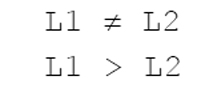 where L1 is a distance between the
 first contact portion 206 and the center of the heating unit 5, and L2 is a distance between the second contact portion 207 and the center of the heating unit 5. An outer tilted portion 23a is integrally formed between the first contact portion 206 and the second contact portion 207 of the partition plate 200. Since an inner tilted portion 23b is formed inside the second contact portion 207, the outer tilted portion 23a is elastically deformed from a virtual line position to a solid line position. The inner tilted portion 23b is also slightly elastically deformed.
The elastic deformation of the outer tilted portion 23a and the inner tilted portion 23b eliminates a difference in dimension between the height of the partition plate 200 and the inner height of the mixing part 16, and acts in a direction that reduces a clearance between the first contact portion 206 of the partition plate 200 and the bottom plate 21 of the mixing part 16 and a clearance between the second contact portion 207 of the partition plate 200 and the top plate 22 of the mixing part 16. In the state of FIG. 5(b), the top plate 22 of the mixing part 16 is joined and fixed to the converting part 11 by welding, brazing, and so on.
In the present embodiment, mixing capability equal to or higher than that of the configuration of FIG. 23 was obtained only by the partition plate 200 fabricated by press working, without additional fixation by welding and so on. Hence, the cost of components and the manufacturing steps were considerably reduced. In the present embodiment, elasticity was obtained by setting the thickness of the partition plate 200 at 0.3 mm relative to the structure having a thickness of 0.8 mm to 1.0 mm. Although the partition plate 200 is desirably made of a spring material, stainless was used instead as in the structure in consideration of heat resistance and cost. The partition plate 200 is fixed while being compressed by 0.1 mm to 0.3 mm in the axial direction, so that the first contact portion 206 is in contact with the outer surface of the converting part 11 and the second contact portion 207 is in contact with the outer surface of the CO removing part 14. The amount of compression may be, for example, about 1 mm. The inner contact portion 208 is radially fit to the first gas passage with a clearance of 0 mm to 0.4 mm. The contact portion is desirably brought into contact with the first gas passage by tube expansion or caulking, but fitting alone provides sufficient resistance to leakage.
The fitting configuration can reduce a stress applied to the structure as compared with fixation by welding and so on, even in the case where the fuel processor is repeatedly started and stopped to obtain heat shrinkage by heating and cooling. Thus, it is expected to prevent problems caused by fatigue breakdown in an extended period of use.
The mixing passage of this configuration has a length of about 380 mm. The mixing distance is at least two times larger than that of the configuration of the fuel processor in FIG. 23, that is, about 180 mm with an identical output and a substantially equal product outside diameter. Thus, stable mixing capability can be provided and high robustness is expected even under deteriorated conditions such as aged deterioration.
The effect of the first embodiment was examined using analysis results in FIG. 4. A three-dimensional model was used for the analysis. General-purpose thermal-liquid analysis software, "ANSYS FLUENT 12.1" of ANSYS, Inc. was used.
The flow rate of air was 7.67 * 10-6 kg/s, the air temperature was 25 degrees C, the flow rate of hydrogen containing gas was 1.69 * 10-4 kg/s, and the temperature of the hydrogen containing gas was 200 degrees C. The hydrogen containing gas contained 3.1% methane, 21.2% steam, 15.2% carbon dioxide, 0.2% carbon monoxide, and 60.3% hydrogen.
Mole ratios O2/CO of a concentration of oxygen O2 to a concentration of carbon monoxide CO in mixed gas in the outer passage 201 and the inner passage 202 were measured at cross-sectional positions B-B, C-C, D-D, E-E, F-F, G-G, H-H, and I-I in the air mixing space of the mixing part 16 in FIG. 4.
 (H) is at least 3.30 and (L) is 1.50 or less.
In an analysis evaluation, a mole ratio O2/CO of a concentration of oxygen O2 to a concentration of carbon monoxide CO was measured in a flow of mixed gas. Since O2 is contained in the air and CO is contained in hydrogen containing gas, small variations in O2/CO indicate sufficient mixing. In requirements specifications determined by the characteristics of the CO removal catalyst, ratios O2/CO in mixed gas are within the range of 1.8 to 3.0.
Furthermore, in requirements specifications for a pressure loss determined by the performance of a pump, a pressure loss is suppressed to 500 Pa or less.
According to the analysis results, O2/CO values substantially converge in the outer passage 201 and stay within the range of 1.86 to 2.13 in the side hole 204. In other words, mixing is fully completed at this point. After that, the gas is further mixed through the inner passage 202 where O2/CO values converge within the range of 1.95 to 2.04 and hardly change. Thus, it was confirmed that this configuration has sufficient mixing capability and high robustness with a sufficient margin.
An analyzed pressure loss at this point was 402 Pa, which satisfied the specifications.
The side hole 204 and the gas outlet 205 were small in an initial design, and thus a pressure loss considerably exceeded a permissible value. The side hole 204 and the gas outlet 205 were then sequentially increased in size, which hardly affected mixing and smoothly reduced the pressure loss. Finally, the current size was set in view of balance with workability.
In the fitting configuration, manufacturing variations may cause clearances. Thus, a maximum amount of clearance was determined by repeated assembling. The first contact portion 206 on the outer surface of the converting part 11 had a maximum clearance of 0.2 mm, and the second contact portion 207 on the outer surface of the CO removing part 14 had a maximum clearance of 0.2 mm. The inner contact portion 208 on the first gas passage had a maximum clearance of 0.4 mm. These clearances were applied to a model as worst conditions although such a case may hardly be considered to actually occur, and then the model was analyzed. Consequently, the terminal end of the mixing passage had a value of 1.82 to 2.34, which satisfies the specifications. Thus, sufficient mixing capability can be obtained in the fitting configuration. A pressure loss decreases to 208 Pa in the worst conditions.
As an example, a fuel processor including the mixing part 16 of the first embodiment was actually fabricated to conduct an operation test. A CO concentration in produced hydrogen containing gas was 10 ppm or less, which means that CO was normally reduced. In a continuous operation of 4600 hours to the present time and 1570 start-stop tests, an abnormal CO concentration or an abnormal pressure loss was not found.
(Second Embodiment)
(Second Embodiment)
FIGS. 6 and 7 illustrate a second embodiment according to the present invention.
In the first embodiment, the mixing passage is divided into the outer passage 201 and the inner passage 202, whereas in the second embodiment, a mixing passage is divided into three or more passages (four passages in the present embodiment).
FIG. 6 illustrates a longitudinal section of the configuration of a principle part. FIG. 7 is a cross-sectional view taken along line J-J. The cross-sectional view basically illustrates only a cross section. For explanation, the projected shape of only a gas inlet port 203 is illustrated. A hollow arrow F1 indicates a flow of reformed hydrogen containing gas, a black arrow F2 indicates an air flow, and a cross hatching arrow F3 indicates a flow of mixed gas.
Air containing oxygen O2 from an air inlet port 16a connected to a side wall flows into the air mixing space of a mixing part 16. Moreover, CO in hydrogen containing gas is reduced by a converting part 11 to a low concentration (0.5% or less), and then the hydrogen containing gas containing the low concentration of CO flows into the air mixing space of the mixing part 16 from the gas inlet port 203. The air and the hydrogen containing gas vertically collide with each other, and then are dispersed so as to start mixing. After that, mixed gas having traveled halfway around an outer passage 201 passes through a side hole 204 formed on the side of a partition plate and flows into a first intermediate passage 209. The mixed gas further travels halfway through the first intermediate passage 209, passes through a second side hole 204a, a second intermediate passage 210, and a third side hole 204b, and then flows into an inner passage 202. The subsequent flow is identical to that of the first embodiment.
The mixing passage of this configuration has a length of about 750 mm. The mixing distance is at least four times larger than that of the configuration of the fuel processor in FIG. 23, that is, about 180 mm with an identical output and a substantially equal product outside diameter. Thus, higher robustness can be obtained.
Currently, as indicated by dimension lines in FIG. 1, the heating unit 5 has an outside diameter of 79 mm and the fuel processor has an outside diameter of 144 mm in view of a catalyst amount determined by an output. The product outside diameter may be reduced by the development of small-size and low-output models and a catalyst having a honeycomb configuration. Also in this case, a mixing distance hardly changes, and thus the volume of the air mixing space of the mixing part 16 may relatively increase. Also in this case, this configuration can achieve sufficient mixing capability without increasing the air mixing space even if the outside diameter decreases.
As in the first embodiment, a partition plate 200 has tilted portions in the second embodiment. Specifically, tilted portions 23a, 23a2, 23a3, and 23b in FIG. 6 are provided. The tilted portions allow the elastic deformation of the outer tilted portion 23a, the inner tilted portion 23b, and the tilted portions 23a2 and 23a3 to eliminate a dimensional difference between the height of the partition plate 200 and the inner height of the mixing part 16 when a CO removing part 14 is attached.
(Third Embodiment)
(Third Embodiment)
FIGS. 8 to 11 and 21 illustrate a third embodiment of the present invention.
In the second embodiment, a gas outlet 205 connecting from the mixing part 16 to the CO removing part 14 is formed on a part of the partition plate 200, whereas in the third embodiment, a gas outlet 205 is formed on a top plate 22 of a mixing part 16. A partition plate 200 of the third embodiment has a first contact portion 206 in contact with a bottom plate 21 of the mixing part 16 and second and third contact portions 207a and 207b in contact with the top plate 22 of the mixing part 16. The following relationships are obtained:
 where L1 is a distance between the
 first contact portion 206 and a heating unit 5, L2 is a distance between the second contact portion 207a and the heating unit 5, and L3 is a distance between the third contact portion 207b and the heating unit 5 (FIG. 11(a)). Moreover, a groove 24 is formed between the second contact portion 207a and the third contact portion 207b of the partition plate 200 so as to protrude to the bottom plate 21. The first contact portion 206 is formed on a part of a bottom 24a of the groove 24. An outer tilted portion 23a is formed on a connecting portion between the outer side of the first contact portion 206 and the bottom 24a. An inner tilted portion 23b is formed on a connecting portion between the inner side of the first contact portion 206 and the bottom 24a.
FIG. 11 shows the step of attaching the partition plate 200 into the mixing part 16.
FIG. 11(a) shows the partition plate 200 having been inserted into the outer periphery of the heating unit 5 before the top plate 22 of the mixing part 16 is fixed. In this state, the first contact portion 206 of the partition plate 200 is in contact with the bottom plate 21 of the mixing part 16.
When the top plate 22 of the mixing part 16 is attached, as illustrated in FIG. 11(b), the second and third contact portions 207a and 207b of the partition plate 200 are pressed. The partition plate 200 is further pressed in a direction that reduces a clearance between the first contact portion 206 and the bottom plate 21 and a clearance between the second and third contact portions 207a and 207b and the top plate 22. Furthermore, the bottom 24a of the groove 24 is elastically deformed from a virtual line position to a solid line position. The outer tilted portion 23a and the inner tilted portion 23b are also slightly elastically deformed. In the state of FIG. 11(b), the top plate 22 is joined and fixed to a converting part 11 by welding, brazing, and so on.
Because of
 a part of the
 partition plate 200 is elastically deformed to eliminate a dimensional difference between the height of the partition plate 200 and the inner height of the mixing part 16, acting in a direction that reduces a clearance between the first contact portion 206 of the partition plate 200 and the bottom plate 21 and a clearance between the second and third contact portions 207a and 207b of the partition plate 200 and the top plate 22.
As illustrated in FIG. 9, an air flow (F2) into an outer passage 201 and a flow of reformed hydrogen containing gas (F1) flow together in a circumferential direction, and then the mixed gas flows into an inner passage 202 through a side hole 204 formed at 180 degrees from an inlet position. The mixed gas further flows together in the inner passage 202 in the circumferential direction, passes through a gas outlet 205, and then flows into a CO removing part 14.
In the third embodiment, a projecting portion having the outer tilted portion 23a and the inner tilted portion 23b is formed on a part of the bottom 24a of the groove 24 of the partition plate 200, forming the first contact portion 206. As illustrated in FIG. 21, a projecting portion with an erect wall surface 25 may be provided without the outer tilted portion 23a and the inner tilted portion 23b, which may achieve substantially the same effect.
The partition plate 200 brings the first contact portion 206 into contact with the bottom plate 21 and the second and third contact portions 207a and 207b into contact with the top plate 22 to elastically deform the bottom 24a of the groove 24 of the partition plate 200 so as to protrude to the top plate 22. The partition plate 200 may bring the first contact portion 206 into contact with the top plate 22 and the second and third contact portions 207a and 207b into contact with the bottom plate 21 to elastically deform the bottom 24a of the groove 24 of the partition plate 200 so as to protrude to the bottom plate 22.
(Fourth Embodiment)
(Fourth Embodiment)
FIGS. 12 and 13 illustrate a fourth embodiment of the present invention.
The fourth embodiment is different from the third embodiment in the shape of a partition plate 200, but the same relationships
 are obtained. In the fourth embodiment, a
 V groove 26 including an outer tilted portion 23a and an inner tilted portion 23b is formed between a second contact portion 207a and a third contact portion 207b of the partition plate 200. A first contact portion 206 is formed at the center of the bottom of the V groove 26.
FIG. 13 shows the step of attaching the partition plate 200 into a mixing part 16.
FIG. 13(a) shows the partition plate 200 having been inserted into the outer periphery of a heating unit 5 before a top plate 22 of the mixing part 16 is fixed. In this state, the first contact portion 206 of the partition plate 200 is in contact with a bottom plate 21 of the mixing part 16.
When the top plate 22 of the mixing part 16 is attached, as illustrated in FIG. 13(b), the second and third contact portions 207a and 207b of the partition plate 200 are pressed. The partition plate 200 is further pressed in a direction that reduces a clearance between the first contact portion 206 and the bottom plate 21 and a clearance between the second and third contact portions 207a and 207b and the top plate 22. Furthermore, the outer tilted portion 23a and the inner tilted portion 23b of the partition plate 200 are elastically deformed from a virtual line position to a solid line position. In the state of FIG. 13(b), the top plate 22 is joined and fixed to the converting part 11 by welding, brazing, and so on.
Because of
 a part of the
 partition plate 200 is elastically deformed to eliminate a dimensional difference between the height of the partition plate 200 and the inner height of the mixing part 16, acting in a direction that reduces a clearance between the first contact portion 206 of the partition plate 200 and the bottom plate 21 and a clearance between the second and third contact portions 207a and 207b of the partition plate 200 and the top plate 22.
An air flow (F2) into an outer passage 201 and a flow of reformed hydrogen containing gas (F1) are identical to those of the second embodiment.
(Fifth Embodiment)
(Fifth Embodiment)
FIGS. 14 and 15 illustrate a fifth embodiment of the present invention.
In the foregoing embodiments, a flow of reformed hydrogen containing gas (F1) flows into the outer passage 201 of the mixing part 16 from the converting part 11 provided under the mixing part 16, and an air flow (F2) flows into the outer passage 201 from the outer periphery of the mixing part 16 and then flows into the CO removing part 14, which is disposed on the mixing part 16, from the inner passage 202 of the mixing part 16 through the gas outlet 205. In the fifth embodiment, a converting part 11 is formed on a mixing part 16 while a CO removing part 14 is disposed under the mixing part 16. A gas outlet 205 is formed on a bottom plate 21 of the mixing part 16.
The mixing part 16 is divided into an outer passage 201 and an inner passage 20 by a ring-shaped partition plate 200. The partition plate 200 includes a first contact portion 206 in contact with the bottom plate 21 on the inner periphery of the mixing part 16 and a first contact portion 206 in contact with the top plate 22 on the outer periphery of the mixing part 16.
The following relationships are obtained:
 where L1 is a distance between the
 first contact portion 206 and a heating unit 5, and L2 is a distance between a second contact portion 207a and the heating unit 5. A ring-shaped tilted portion 23 is integrally formed between the first contact portion 206 and the second contact portion 207a.
The following relationships are obtained:
FIG. 15 shows the step of attaching the partition plate 200 into the mixing part 16.
FIG. 15(a) shows the partition plate 200 having been inserted into the outer periphery of the heating unit 5 before a top plate 22 of the mixing part 16 is fixed. In this state, the first contact portion 206 of the partition plate 200 is in contact with the bottom plate 21 of the mixing part 16.
When the top plate 22 is attached, as illustrated in FIG. 15(b), the second contact portion 207a of the partition plate 200 is pressed. The partition plate 200 is further pressed in a direction that reduces a clearance between the first contact portion 206 and the bottom plate 21 and a clearance between the second contact portion 207a and a third contact portion 207b and the top plate 22. Furthermore, the tilted portion 23 is elastically deformed from a virtual line position to a solid line position. In the state of FIG. 11(b), the top plate 22 is joined and fixed to the CO removing part 14 by welding, brazing, and so on.
Because of
a part of thepartition plate 200 is elastically deformed to eliminate a dimensional difference between the height of the partition plate 200 and the inner height of the mixing part 16, acting in a direction that reduces a clearance between the first contact portion 206 of the partition plate 200 and the bottom plate 21 and a clearance between the second contact portion 207a of the partition plate 200 and the top plate 22.
a part of the
As illustrated in FIG. 14, an air flow (F2) into an inner passage 202 and a flow of reformed hydrogen containing gas (F1) flow together in a circumferential direction, and then the mixed gas flows into the outer passage 201 through a side hole 204 formed at 180 degrees from an inlet position. The mixed gas further flows together in the outer passage 201 in the circumferential direction, passes through the gas outlet 205, and then flows into the CO removing part 14.
(Sixth Embodiment)
(Sixth Embodiment)
FIGS. 16 and 17 illustrate a sixth embodiment of the present invention.
A converting part 11 is disposed on a mixing part 16 while a CO removing part 14 is disposed under the mixing part 16, which is similar to the configuration of the fifth embodiment. In the fifth embodiment, the inside of the mixing part 16 is divided into the outer passage 201 and the inner passage 202 by the partition plate 200, whereas in the sixth embodiment, the inside of the mixing part 16 is divided into an upper passage 27 and a lower passage 28 by a partition plate 200. The sixth embodiment is different from the fifth embodiment in that the ring-shaped partition plate 200 is joined and fixed to the inner surface of the mixing part 16 via 29a and 29b by welding, brazing, and so on.
An air flow (F2) into an inner passage 202 and a flow of reformed hydrogen containing gas (F1) pass together through the upper passage 27 in a circumferential direction, and then the mixed gas flows into the lower passage 28 through a hole 30 formed at 180 degrees from an inlet position. The mixed gas further passes through the lower passage 27 in the circumferential direction and then flows into the CO removing part 14 through a gas outlet 205.
(Seventh Embodiment)
(Seventh Embodiment)
FIGS. 18 and 19 illustrate a seventh embodiment of the present invention.
In the foregoing embodiments, the inside of the mixing part 16 is divided into a plurality of passages by the ring-shaped partition plate 200. The seventh embodiment is different from the foregoing embodiments in that the inside of a mixing part 16 is divided into a plurality of passages by a plurality of ring-shaped partition plates.
A specific example of the seventh embodiment is a modification of the third embodiment illustrated in FIGS. 8 to 11. This modification can be similarly implemented in other embodiments.
As illustrated in FIG. 18, partition plates 200a and 200b are attached into the mixing part 16 to divide the mixing part 16 into an outer passage 201 and first and second inner passages 202a and 202b. The partition plate 200a is identical to the partition plate 200 of FIG. 3.
An air flow (F2) into the outer passage 201 and a flow of reformed hydrogen containing gas (F1) pass together through the outer passage 201 in a circumferential direction, and then the mixed gas flows into the first inner passage 202a through a side hole 204 formed at 180 degrees from an inlet position. The mixed gas further passes through the first inner passage 202a in the circumferential direction and flows into the second inner passage 202b through an inlet 31 formed on the partition plate 200b. The inlet 31 is formed at 180 degrees from the side hole 204 in the circumferential direction.
The mixed gas in the second inner passage 202b further flows in the circumferential direction therefrom, passes through a gas outlet 205 formed on a top plate 22, and flows into a third gas passage 12. The inside of the first inner passage 202a is further divided into the passages by the second inner passage 202b, achieving a longer passage length than in the third embodiment.
FIG. 19 shows the step of attaching the partition plates 200a and 200b into the mixing part 16.
FIG. 19(a) shows the partition plates 200a and 200b having been stacked and inserted into the outer periphery of a heating unit 5 before the top plate 22 of the mixing part 16 is fixed.
In this state, a first contact portion 206 of the partition plate 200a is in contact with a bottom plate 21 of the mixing part 16. Moreover, a fourth contact portion 206b of the partition plate 200b is in contact with a bottom 24a of a groove 24 on the partition plate 200a.
When the top plate 22 is attached, as illustrated in FIG. 19(b), a second contact portion 207a of the partition plate 200a is pressed through a fifth contact portion 207c of the partition plate 200b while a third contact portion 207b of the partition plate 200a is pressed through a sixth contact portion 207d of the partition plate 200b.
Hence, the bottom plate 24a of the partition plate 200a is elastically deformed from a virtual line position to a solid line position. Furthermore, a tilted portion 32 formed between the fourth contact portion 206b and the fifth contact portion 207c of the partition plate 200b and a side 33 formed between the fourth contact portion 206b and the sixth contact portion 207d of the partition plate 200b are also elastically deformed from virtual line positions to solid line positions. In the state of FIG. 19(b), the top plate 22 is joined and fixed to a converting part 11 by welding, brazing, and so on.
The following relationships are obtained:
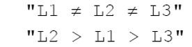 Furthermore, the following relationships are obtained:
 where L4 is a distance between the fourth contact portion 206b and the
 heating unit 5, L5 is a distance between the fifth contact portion 207c and the heating unit 5, and L6 is a distance between the seventh contact portion 207d and the heating unit 5. Thus, a part of the partition plates 200a and 200b is elastically deformed to eliminate a dimensional difference between the height of the partition plates 200a and 200b and the inner height of the mixing part 16, acting in a direction that reduces a clearance between the first contact portion 206 and the bottom plate 21, a clearance between the second and third contact portions 207a and 207b of the partition plate 200a and the partition plate 200b, a clearance between the fourth contact portion 206b and the partition plate 200a, and a clearance between the partition plate 200b and the top plate 22.
The following relationships are obtained:
In the seventh embodiment, a projecting portion having an outer tilted portion 23a and an inner tilted portion 23b is formed on a part of the bottom 24a of the groove 24 on the partition plate 200a, forming the first contact portion 206. The partition plate 200a may be identical in shape to the partition plate 200 in FIG. 21 to achieve substantially the same effect.
(Eighth Embodiment)
(Eighth Embodiment)
FIG. 20 illustrates an eighth embodiment of the present invention.
In the foregoing embodiments, mixed gas flows from one passage to another through the hole with the partition plate dividing the passage into the multiple passages. The hole may be replaced with a notch. Specifically, the side hole 204 is a circular hole in FIGS. 9 and 10 of the third embodiment and may be replaced with a notch 34 in FIG. 20.
In the foregoing embodiments other than the sixth embodiment, the partition plate is not joined or fixed to any one of the partition wall of the mixing part 16, the bottom plate 21 near the converting part 11, and the top plate 22 near the CO removing part 14 by welding, brazing, and so on. At least a part of the partition plate may be joined and fixed to one of the bottom plate 21 and the top plate 22 by welding, brazing, and so on.
A fuel processor according to the present invention can remarkably improve the robustness of mixing capability with a simple structure without increasing a pressure loss. The fuel processor is used for fuel cells in, for example, a home cogeneration system to exhibit constant CO removal capability over a long continuous operation even if a load fluctuates.
1 fuel processor
1a heat insulating material
2 burner
3 heat chamber
4 exhaust passage
4a outlet port of theexhaust passage 4
5 heating unit
6 first gas passage
6a inlet of thegas passage 6
7 reforming catalyst
8 reforming part
9 second gas passage
10 CO converter catalyst
11 converting part
12 third gas passage
12a outlet port of the third gas passage
13 CO removal catalyst
14 CO removing part
15 heating coil
16 mixing part
16a air inlet port
17 hydrogen containing gas outlet port
21 bottom plate of the mixingpart 16
22 top plate of the mixingpart 16
23a outer tilted portion
23b inner tilted portion
L1 distance between thefirst contact portion 206 and the center of the heating unit 5
L2 distance between thesecond contact portion 207 and the center of the heating unit 5
24 groove
24a bottom of thegroove 24
25 erect wall surface
26 V groove
27 upper passage
28 lower passage
29a, 29b welding and brazing points
30 hole
31 inlet
70 source gas
71 air
72 reformed water
73 hydrogen containing gas
74 exhaust gas
100 mixing passage
101 air inlet port
110 gas supply region
111 gas supply port
120 gas diffusion region
200, 200a, 200b partition plate
201 outer passage
202 inner passage
203 gas inlet port
204 side hole
204a second side hole
204b third side hole
205 gas outlet
206 first contact portion
207 second contact portion
207a, 207b second and third contact portions
208 inner contact portion
209 first intermediate passage
210 second intermediate passage
1a heat insulating material
2 burner
3 heat chamber
4 exhaust passage
4a outlet port of the
5 heating unit
6 first gas passage
6a inlet of the
7 reforming catalyst
8 reforming part
9 second gas passage
10 CO converter catalyst
11 converting part
12 third gas passage
12a outlet port of the third gas passage
13 CO removal catalyst
14 CO removing part
15 heating coil
16 mixing part
16a air inlet port
17 hydrogen containing gas outlet port
21 bottom plate of the mixing
22 top plate of the mixing
23a outer tilted portion
23b inner tilted portion
L1 distance between the
L2 distance between the
24 groove
24a bottom of the
25 erect wall surface
26 V groove
27 upper passage
28 lower passage
29a, 29b welding and brazing points
30 hole
31 inlet
70 source gas
71 air
72 reformed water
73 hydrogen containing gas
74 exhaust gas
100 mixing passage
101 air inlet port
110 gas supply region
111 gas supply port
120 gas diffusion region
200, 200a, 200b partition plate
201 outer passage
202 inner passage
203 gas inlet port
204 side hole
204a second side hole
204b third side hole
205 gas outlet
206 first contact portion
207 second contact portion
207a, 207b second and third contact portions
208 inner contact portion
209 first intermediate passage
210 second intermediate passage
Claims (10)
- A fuel processor comprising:
a reforming part that is provided around a heating unit including a burner and generates hydrogen containing gas composed of carbon monoxide and water;
a converting part that is provided around the heater and generates hydrogen containing gas composed of low-concentration carbon monoxide by reacting carbon monoxide and water in the hydrogen containing gas generated in the reforming part;
a mixing part that is provided around the heater and mixes air supplied from an air inlet port and the hydrogen containing gas generated in the converting part; and
a CO removing part that reacts oxygen, carbon monoxide in the gas supplied from the mixing part, and a CO removal catalyst to generate hydrogen containing gas hardly containing carbon monoxide,
the fuel processor further comprising a partition plate that divides a passage of the mixing part, the partition plate partially including a tilted portion. - The fuel processor according to claim 1, wherein the mixing part is formed between a first partition near the converting part and a second partition near the CO removing part, and a relationship is established below:
where L1 is a distance from the heating unit to a first contact portion between the partition plate and one of the first and second partitions, and
L2 is a distance from the heating unit to a second contact portion between the partition plate and the other of the first and second partitions. - The fuel processor according to claim 1, wherein the partition plate is elastically deformed on the tilted portion.
- The fuel processor according to claim 1, wherein the partition plate divides inside of the mixing part into at least two concentric passages.
- The fuel processor according to claim 1, wherein the mixing part is formed between a first partition near the converting part and a second partition near the CO removing part, and
the partition plate has a fitting structure unfixed to at least one of the first partition and the second partition. - The fuel processor according to claim 1, wherein the mixing part is formed between a first partition near the converting part and a second partition near the CO removing part, and a relationship is established below:
where L1 is a distance from the heating unit to a first contact portion between the partition plate and one of the first and second partitions,
L2 is a distance from the heating unit to a second contact portion between the partition plate and one of the first and second partitions, and
L3 is a distance from the heating unit to a third contact portion between the partition plate and one of the first and second partitions. - The fuel processor according to claim 1, wherein the mixing part is formed between a first partition near the CO removing part and a second partition near the converting part, and a relationship is established below:
where L1 is a distance from the heating unit to a first contact portion between the partition plate and one of the first and second partitions, and
L2 is a distance from the heating unit to a second contact portion between the partition plate and the other of the first and second partitions. - A fuel processor comprising:
a reforming part that is provided around a heating unit including a burner and generates hydrogen containing gas composed of carbon monoxide and water;
a converting part that is provided around the heater and generates hydrogen containing gas composed of low-concentration carbon monoxide by reacting carbon monoxide and water in the hydrogen containing gas generated in the reforming part;
a mixing part that is provided around the heater and mixes air supplied from an air inlet port and the hydrogen containing gas generated in the converting part; and
a CO removing part that reacts oxygen, carbon monoxide in the gas supplied from the mixing part, and a CO removal catalyst to generate hydrogen containing gas hardly containing carbon monoxide,
the fuel processor further comprising a partition plate that divides a passage of the mixing part at least into first and second passages,
the partition plate including an inlet of mixed gas from the first passage to the second passage, the inlet being located at or substantially at 180 degrees in the circumferential direction with respect to an inlet position of the mixed gas in the first passage. - A fuel processor comprising:
a reforming part that is provided around a heating unit including a burner and generates hydrogen containing gas composed of carbon monoxide and water;
a converting part that is provided around the heater and generates hydrogen containing gas composed of low-concentration carbon monoxide by reacting carbon monoxide and water in the hydrogen containing gas generated in the reforming part;
a mixing part (16) that is provided around the heater and mixes air supplied from an air inlet port and the hydrogen containing gas generated in the converting part;
a CO removing part that reacts oxygen, carbon monoxide in the gas supplied from the mixing part, and a CO removal catalyst to generate hydrogen containing gas hardly containing carbon monoxide; and
a partition plate that divides a passage of the mixing part at least into first and second passages,
wherein the mixing part is formed between a first partition near the converting part and a second partition near the CO removing part,
the partition plate has a groove extended around the heater in a circumferential direction, and
the groove has a bottom that is in contact with one of the first and second partitions and is partially elastically deformed so as to protrude to the other of the first and second partitions. - The fuel processor according to claim 9, wherein the bottom of the partition plate is in contact with the first partition near the converting part and is elastically deformed so as to protrude to the second partition near the CO removing part.
Priority Applications (2)
| Application Number | Priority Date | Filing Date | Title |
|---|---|---|---|
| JP2014514253A JP5958721B2 (en) | 2012-02-09 | 2013-01-18 | Fuel processor |
| EP13712935.9A EP2812107B1 (en) | 2012-02-09 | 2013-01-18 | Fuel processor |
Applications Claiming Priority (2)
| Application Number | Priority Date | Filing Date | Title |
|---|---|---|---|
| JP2012025645 | 2012-02-09 | ||
| JP2012-025645 | 2012-02-09 |
Publications (2)
| Publication Number | Publication Date |
|---|---|
| WO2013118430A2 true WO2013118430A2 (en) | 2013-08-15 |
| WO2013118430A3 WO2013118430A3 (en) | 2013-12-19 |
Family
ID=48014231
Family Applications (1)
| Application Number | Title | Priority Date | Filing Date |
|---|---|---|---|
| PCT/JP2013/000218 Ceased WO2013118430A2 (en) | 2012-02-09 | 2013-01-18 | Fuel processor |
Country Status (3)
| Country | Link |
|---|---|
| EP (1) | EP2812107B1 (en) |
| JP (1) | JP5958721B2 (en) |
| WO (1) | WO2013118430A2 (en) |
Cited By (1)
| Publication number | Priority date | Publication date | Assignee | Title |
|---|---|---|---|---|
| JP2022124549A (en) * | 2021-02-16 | 2022-08-26 | パナソニックIpマネジメント株式会社 | Hydrogen production device |
Families Citing this family (2)
| Publication number | Priority date | Publication date | Assignee | Title |
|---|---|---|---|---|
| JP6646814B2 (en) * | 2017-01-24 | 2020-02-14 | パナソニックIpマネジメント株式会社 | Hydrogen generator |
| JP7349604B2 (en) * | 2021-01-07 | 2023-09-25 | パナソニックIpマネジメント株式会社 | hydrogen generator |
Citations (4)
| Publication number | Priority date | Publication date | Assignee | Title |
|---|---|---|---|---|
| JP2002187705A (en) | 2000-10-10 | 2002-07-05 | Tokyo Gas Co Ltd | Single tube cylindrical reformer |
| JP4536153B2 (en) | 2008-06-13 | 2010-09-01 | パナソニック株式会社 | Fuel processor |
| JP4542205B2 (en) | 2008-05-30 | 2010-09-08 | パナソニック株式会社 | Fuel processor |
| JP2011178613A (en) | 2010-03-02 | 2011-09-15 | Tokyo Gas Co Ltd | Multiple cylindrical steam reformer |
Family Cites Families (10)
| Publication number | Priority date | Publication date | Assignee | Title |
|---|---|---|---|---|
| US7182921B2 (en) * | 2001-06-04 | 2007-02-27 | Tokyo Gas Co., Ltd. | Cylindrical steam reforming unit |
| DE60222123T2 (en) * | 2001-06-04 | 2007-12-20 | Tokyo Gas Co. Ltd. | CYLINDRICAL WATER VAPOR REFORMING UNIT |
| JP4128804B2 (en) * | 2002-02-05 | 2008-07-30 | 荏原バラード株式会社 | Fuel reformer |
| JP2003321206A (en) * | 2002-05-08 | 2003-11-11 | Tokyo Gas Co Ltd | Single tube cylindrical reformer |
| US20070070807A1 (en) * | 2003-05-19 | 2007-03-29 | Maarten Bracht | Process to upgrade kerosenes and a gasoils from naphthenic and aromatic crude petroleum sources |
| WO2005000737A1 (en) * | 2003-06-27 | 2005-01-06 | Ebara Ballard Corporation | Fuel reformer |
| WO2005056468A1 (en) * | 2003-12-09 | 2005-06-23 | Matsushita Electric Industrial Co., Ltd. | Hydrogen generating apparatus |
| JP4870491B2 (en) * | 2005-07-27 | 2012-02-08 | 富士電機株式会社 | Fuel reformer |
| JP5301419B2 (en) * | 2008-12-03 | 2013-09-25 | 東京瓦斯株式会社 | Multi-cylinder steam reformer for fuel cells |
| JP5371013B2 (en) * | 2010-03-02 | 2013-12-18 | 東京瓦斯株式会社 | Multi-cylinder steam reformer |
-
2013
- 2013-01-18 JP JP2014514253A patent/JP5958721B2/en not_active Expired - Fee Related
- 2013-01-18 EP EP13712935.9A patent/EP2812107B1/en active Active
- 2013-01-18 WO PCT/JP2013/000218 patent/WO2013118430A2/en not_active Ceased
Patent Citations (4)
| Publication number | Priority date | Publication date | Assignee | Title |
|---|---|---|---|---|
| JP2002187705A (en) | 2000-10-10 | 2002-07-05 | Tokyo Gas Co Ltd | Single tube cylindrical reformer |
| JP4542205B2 (en) | 2008-05-30 | 2010-09-08 | パナソニック株式会社 | Fuel processor |
| JP4536153B2 (en) | 2008-06-13 | 2010-09-01 | パナソニック株式会社 | Fuel processor |
| JP2011178613A (en) | 2010-03-02 | 2011-09-15 | Tokyo Gas Co Ltd | Multiple cylindrical steam reformer |
Cited By (2)
| Publication number | Priority date | Publication date | Assignee | Title |
|---|---|---|---|---|
| JP2022124549A (en) * | 2021-02-16 | 2022-08-26 | パナソニックIpマネジメント株式会社 | Hydrogen production device |
| JP7373706B2 (en) | 2021-02-16 | 2023-11-06 | パナソニックIpマネジメント株式会社 | hydrogen generator |
Also Published As
| Publication number | Publication date |
|---|---|
| EP2812107B1 (en) | 2021-03-31 |
| JP2014530159A (en) | 2014-11-17 |
| WO2013118430A3 (en) | 2013-12-19 |
| JP5958721B2 (en) | 2016-08-02 |
| EP2812107A2 (en) | 2014-12-17 |
Similar Documents
| Publication | Publication Date | Title |
|---|---|---|
| JP5807173B2 (en) | Hydrogen generator and fuel cell system provided with the same | |
| JP5044048B2 (en) | Hydrogen generator | |
| US12027733B2 (en) | Fuel cell system including ATO injector and method of operating the same | |
| US9941535B2 (en) | Fuel cell module | |
| JP6291375B2 (en) | Fuel cell module | |
| WO2013118430A2 (en) | Fuel processor | |
| US20180301718A1 (en) | Fuel cell system | |
| EP3088828B1 (en) | Heat exchanger, method of producing heat exchanger, and fuel cell system | |
| EP2554512A1 (en) | Hydrogen production apparatus and fuel cell system | |
| JP5927572B2 (en) | Hydrodesulfurization device, hydrogen generator, and fuel cell system | |
| US10833339B2 (en) | Fuel cell system and method of running fuel cell system | |
| JP4979354B2 (en) | Hydrogen generator and fuel cell system | |
| JP7756303B2 (en) | Hydrogen generator | |
| US11923572B2 (en) | Fuel cell module | |
| JP2009274886A (en) | Combustion apparatus for reforming apparatus, reforming apparatus, and fuel cell system | |
| JP6512530B2 (en) | Solid oxide fuel cell device | |
| CN118435402A (en) | Fuel cell device | |
| JP5534901B2 (en) | Hydrogen production apparatus and fuel cell system | |
| JP5336696B2 (en) | Fluid processing apparatus and manufacturing method thereof | |
| JP7615754B2 (en) | Hot Module for Fuel Cells | |
| JP2024066791A (en) | Hydrogen Generator | |
| JP2014005168A (en) | Hydrogen generator and fuel cell system | |
| JP2023136558A (en) | fuel cell module | |
| JP2013180929A (en) | Fuel processor | |
| KR20160094666A (en) | Heat exchanger for fuel reformer of fuel cell system and ato assembly with the same |
Legal Events
| Date | Code | Title | Description |
|---|---|---|---|
| 121 | Ep: the epo has been informed by wipo that ep was designated in this application |
Ref document number: 13712935 Country of ref document: EP Kind code of ref document: A2 |
|
| ENP | Entry into the national phase |
Ref document number: 2014514253 Country of ref document: JP Kind code of ref document: A |
|
| WWE | Wipo information: entry into national phase |
Ref document number: 2013712935 Country of ref document: EP |