WO2013118826A1 - 横型熱処理装置 - Google Patents
横型熱処理装置 Download PDFInfo
- Publication number
- WO2013118826A1 WO2013118826A1 PCT/JP2013/052883 JP2013052883W WO2013118826A1 WO 2013118826 A1 WO2013118826 A1 WO 2013118826A1 JP 2013052883 W JP2013052883 W JP 2013052883W WO 2013118826 A1 WO2013118826 A1 WO 2013118826A1
- Authority
- WO
- WIPO (PCT)
- Prior art keywords
- passage
- heat treatment
- treatment apparatus
- workpiece
- gas
- Prior art date
- Legal status (The legal status is an assumption and is not a legal conclusion. Google has not performed a legal analysis and makes no representation as to the accuracy of the status listed.)
- Ceased
Links
Images


Classifications
-
- D—TEXTILES; PAPER
- D01—NATURAL OR MAN-MADE THREADS OR FIBRES; SPINNING
- D01F—CHEMICAL FEATURES IN THE MANUFACTURE OF ARTIFICIAL FILAMENTS, THREADS, FIBRES, BRISTLES OR RIBBONS; APPARATUS SPECIALLY ADAPTED FOR THE MANUFACTURE OF CARBON FILAMENTS
- D01F9/00—Artificial filaments or the like of other substances; Manufacture thereof; Apparatus specially adapted for the manufacture of carbon filaments
- D01F9/08—Artificial filaments or the like of other substances; Manufacture thereof; Apparatus specially adapted for the manufacture of carbon filaments of inorganic material
- D01F9/12—Carbon filaments; Apparatus specially adapted for the manufacture thereof
- D01F9/14—Carbon filaments; Apparatus specially adapted for the manufacture thereof by decomposition of organic filaments
- D01F9/32—Apparatus therefor
- D01F9/328—Apparatus therefor for manufacturing filaments from polyaddition, polycondensation, or polymerisation products
-
- D—TEXTILES; PAPER
- D02—YARNS; MECHANICAL FINISHING OF YARNS OR ROPES; WARPING OR BEAMING
- D02J—FINISHING OR DRESSING OF FILAMENTS, YARNS, THREADS, CORDS, ROPES OR THE LIKE
- D02J13/00—Heating or cooling the yarn, thread, cord, rope, or the like, not specific to any one of the processes provided for in this subclass
- D02J13/001—Heating or cooling the yarn, thread, cord, rope, or the like, not specific to any one of the processes provided for in this subclass in a tube or vessel
-
- F—MECHANICAL ENGINEERING; LIGHTING; HEATING; WEAPONS; BLASTING
- F27—FURNACES; KILNS; OVENS; RETORTS
- F27B—FURNACES, KILNS, OVENS OR RETORTS IN GENERAL; OPEN SINTERING OR LIKE APPARATUS
- F27B1/00—Shaft or like vertical or substantially vertical furnaces
- F27B1/08—Shaft or like vertical or substantially vertical furnaces heated otherwise than by solid fuel mixed with charge
-
- F—MECHANICAL ENGINEERING; LIGHTING; HEATING; WEAPONS; BLASTING
- F27—FURNACES; KILNS; OVENS; RETORTS
- F27B—FURNACES, KILNS, OVENS OR RETORTS IN GENERAL; OPEN SINTERING OR LIKE APPARATUS
- F27B9/00—Furnaces through which the charge is moved mechanically, e.g. of tunnel type; Similar furnaces in which the charge moves by gravity
- F27B9/04—Furnaces through which the charge is moved mechanically, e.g. of tunnel type; Similar furnaces in which the charge moves by gravity adapted for treating the charge in vacuum or special atmosphere
-
- F—MECHANICAL ENGINEERING; LIGHTING; HEATING; WEAPONS; BLASTING
- F27—FURNACES; KILNS; OVENS; RETORTS
- F27B—FURNACES, KILNS, OVENS OR RETORTS IN GENERAL; OPEN SINTERING OR LIKE APPARATUS
- F27B9/00—Furnaces through which the charge is moved mechanically, e.g. of tunnel type; Similar furnaces in which the charge moves by gravity
- F27B9/14—Furnaces through which the charge is moved mechanically, e.g. of tunnel type; Similar furnaces in which the charge moves by gravity characterised by the path of the charge during treatment; characterised by the means by which the charge is moved during treatment
-
- F—MECHANICAL ENGINEERING; LIGHTING; HEATING; WEAPONS; BLASTING
- F27—FURNACES; KILNS; OVENS; RETORTS
- F27D—DETAILS OR ACCESSORIES OF FURNACES, KILNS, OVENS OR RETORTS, IN SO FAR AS THEY ARE OF KINDS OCCURRING IN MORE THAN ONE KIND OF FURNACE
- F27D7/00—Forming, maintaining or circulating atmospheres in heating chambers
- F27D7/06—Forming or maintaining special atmospheres or vacuum within heating chambers
-
- F—MECHANICAL ENGINEERING; LIGHTING; HEATING; WEAPONS; BLASTING
- F27—FURNACES; KILNS; OVENS; RETORTS
- F27D—DETAILS OR ACCESSORIES OF FURNACES, KILNS, OVENS OR RETORTS, IN SO FAR AS THEY ARE OF KINDS OCCURRING IN MORE THAN ONE KIND OF FURNACE
- F27D99/00—Subject matter not provided for in other groups of this subclass
- F27D99/0073—Seals
- F27D99/0075—Gas curtain seals
-
- F—MECHANICAL ENGINEERING; LIGHTING; HEATING; WEAPONS; BLASTING
- F27—FURNACES; KILNS; OVENS; RETORTS
- F27B—FURNACES, KILNS, OVENS OR RETORTS IN GENERAL; OPEN SINTERING OR LIKE APPARATUS
- F27B9/00—Furnaces through which the charge is moved mechanically, e.g. of tunnel type; Similar furnaces in which the charge moves by gravity
- F27B9/30—Details, accessories or equipment specially adapted for furnaces of these types
- F27B9/38—Arrangements of devices for charging
- F27B2009/382—Charging
-
- F—MECHANICAL ENGINEERING; LIGHTING; HEATING; WEAPONS; BLASTING
- F27—FURNACES; KILNS; OVENS; RETORTS
- F27B—FURNACES, KILNS, OVENS OR RETORTS IN GENERAL; OPEN SINTERING OR LIKE APPARATUS
- F27B9/00—Furnaces through which the charge is moved mechanically, e.g. of tunnel type; Similar furnaces in which the charge moves by gravity
- F27B9/30—Details, accessories or equipment specially adapted for furnaces of these types
- F27B9/38—Arrangements of devices for charging
- F27B2009/384—Discharging
-
- F—MECHANICAL ENGINEERING; LIGHTING; HEATING; WEAPONS; BLASTING
- F27—FURNACES; KILNS; OVENS; RETORTS
- F27B—FURNACES, KILNS, OVENS OR RETORTS IN GENERAL; OPEN SINTERING OR LIKE APPARATUS
- F27B17/00—Furnaces of a kind not covered by any of groups F27B1/00 - F27B15/00
- F27B17/0016—Chamber type furnaces
- F27B2017/0091—Series of chambers, e.g. associated in their use
Definitions
- the present invention relates to a heat treatment apparatus that can be suitably used in a flameproofing furnace for making a carbon fiber precursor fiber bundle flameproof.
- a heat treatment apparatus for continuously heat-treating an object to be processed in manufacturing a long object such as a film, a sheet, a fiber (hereinafter referred to as an object to be processed) is known.
- this heat treatment apparatus for example, in the case of carbon fiber, a precursor fiber made of, for example, polyacrylonitrile fiber is continuously heat treated in a heat treatment chamber.
- decomposition gases such as cyanide, ammonia, and carbon monoxide are generated in the heat treatment chamber by the oxidation reaction of the precursor fibers. This cracked gas needs to be recovered and subjected to gas treatment such as combustion treatment.
- Patent Document 1 in order to prevent such decomposition gas from leaking out of the heat treatment apparatus from the inlet / outlet of the precursor fiber bundle of the heat treatment apparatus, a negative pressure is applied to the interior adjacent to the heat treatment room.
- An air curtain that suppresses inflow of outside air by blowing air outside the heat treatment apparatus toward the object to be processed outside the inlet / outlet of the precursor fiber bundle in the seal chamber.
- the seal chamber connected to the heat treatment chamber is provided in order to prevent the gas in the seal chamber from leaking to the outside even if the ejection speed of the air blown toward the object to be processed is increased. It has been proposed to provide a cylindrical flow straightening member.
- the present invention provides a heat treatment apparatus capable of preventing the gas in the sealing chamber such as cracked gas from leaking to the outside even if the amount of gas for the air curtain sprayed toward the object to be processed is reduced. Objective.
- Another object of the present invention is to provide a method for producing a flame-resistant fiber bundle, a method for producing a carbon fiber bundle, and a heat treatment method using such a heat treatment apparatus.
- a horizontal heat treatment apparatus for continuously heat-treating a continuous flat object to be processed in a horizontal direction in a heat treatment chamber
- a seal chamber to which an exhaust fan is connected is connected to the workpiece inlet and outlet of the heat treatment chamber, respectively, and the seal chamber is configured to allow the workpiece to pass through the seal chamber in the horizontal direction
- a passage having a rectangular cross section is connected to an opening located on the opposite side to the heat treatment chamber of the workpiece inlet / outlet of each seal chamber, and the passage is parallel to the workpiece in the horizontal direction.
- a workpiece to be processed in a passage connected to the workpiece inlet of the seal chamber is a workpiece inlet of the heat treatment apparatus, and a workpiece to be processed in the passage connected to the seal chamber workpiece outlet
- the delivery port is a workpiece delivery port of the heat treatment apparatus
- a pair of nozzles for jetting gas is provided at the upper and lower positions of each passage, The gas outlet of each nozzle is rectangular, In each passage, the pair of nozzles provided in the passage is gas toward the center of the passage in the vertical direction and toward the workpiece inlet or outlet of the heat treatment apparatus included in the passage.
- each passage the gas outlet of each nozzle provided in this passage is parallel to the long side direction of the workpiece inlet and outlet of this passage, and has a length equal to the length of the long side. And having In each passage, a distance d between the gas outlets of the pair of nozzles provided in the passage and the workpiece inlet or outlet of the heat treatment apparatus included in the passage, and the height of the passage Dn is 2 ⁇ d ⁇ 0.75 Dn A horizontal heat treatment apparatus that satisfies the above is provided.
- the distance d is preferably 15 mm or more.
- the opening width Wn of the nozzle is preferably 0.5 mm or more and 3 mm or less, and the height Dn of the passage is preferably 20 mm or more and 78 mm or less.
- the passages are respectively provided at a plurality of positions in the vertical direction so that the workpieces can be transferred in the horizontal direction at the plurality of positions in the vertical direction,
- the seal chamber may be partitioned corresponding to each passage.
- each nozzle has a gas flow rate adjusting mechanism capable of adjusting a gas ejection amount.
- the passage is formed by an upper passage member, a lower passage member, and a side member, Each of the upper and lower passage members has two members across the nozzle, The two members may be integrated with a spacer member that determines a nozzle gap between the two members.
- the two members and the spacer member are detachable.
- the horizontal heat treatment apparatus can be a heat treatment furnace for heat treating the carbon fiber precursor fiber bundle.
- a carbon fiber precursor fiber bundle is heat treated with a horizontal heat treatment apparatus to produce a flame resistant fiber bundle, a method for producing a flame resistant fiber bundle
- the horizontal heat treatment apparatus is a horizontal heat treatment apparatus for continuously heat-treating a continuous flat workpiece while being transferred in a horizontal direction in a heat treatment chamber
- a seal chamber to which an exhaust fan is connected is connected to the workpiece inlet and outlet of the heat treatment chamber, respectively, and the seal chamber is configured to allow the workpiece to pass through the seal chamber in the horizontal direction
- a passage having a rectangular cross section is connected to an opening located on the opposite side to the heat treatment chamber of the workpiece inlet / outlet of each seal chamber, and the passage is parallel to the workpiece in the horizontal direction.
- a workpiece to be processed in a passage connected to the workpiece inlet of the seal chamber is a workpiece inlet of the heat treatment apparatus, and a workpiece to be processed in the passage connected to the seal chamber workpiece outlet
- the delivery port is a workpiece delivery port of the heat treatment apparatus
- a pair of nozzles for jetting gas is provided at the upper and lower positions of each passage, The gas outlet of each nozzle is rectangular, In each passage, the pair of nozzles provided in the passage is gas toward the center of the passage in the vertical direction and toward the workpiece inlet or outlet of the heat treatment apparatus included in the passage.
- each passage the gas outlet of each nozzle provided in this passage is parallel to the long side direction of the workpiece inlet and outlet of this passage, and has a length equal to the length of the long side. And having In each passage, a distance d between the gas outlets of the pair of nozzles provided in the passage and the workpiece inlet or outlet of the heat treatment apparatus included in the passage, and the height of the passage Dn is 2 ⁇ d ⁇ 0.75 Dn A horizontal heat treatment apparatus satisfying the requirements; and -Negative pressure in each seal chamber using said exhaust fan; -In each passage, the gas ejection amount per 1 m of the long side of the inlet and outlet of the object to be processed in this passage is expressed as V (m 3 / h) in each passage. When the gauge pressure in the connected seal chamber is expressed as P (Pa), V ⁇ ⁇ 30 ⁇ P + 21 Jetting gas from each nozzle so that A method for producing a flameproof fiber bundle is provided.
- the flow velocity Vo of the gas flowing into the seal chamber from each passage is 0.1 m / second or more and 0.5 m / second or less.
- the ejection speed Vs of the gas ejected from each nozzle is 3 m / s or more and 30 m / s or less.
- a method for producing a carbon fiber bundle comprising the steps of producing a flame-resistant fiber bundle by the above-mentioned method for producing a flame-resistant fiber bundle, and carbonizing the flame-resistant fiber bundle.
- the heat processing apparatus which can prevent the decomposition gas in sealing chambers, such as decomposition gas, leaking outside is provided. .
- FIG. 1 It is a schematic block diagram which shows an example of the whole structure of the heat processing apparatus in embodiment of this invention. It is a schematic sectional drawing of the air curtain means in embodiment of this invention. It is a disassembled perspective view of the nozzle part of an air curtain means. It is a schematic sectional drawing which shows the whole structure of the test apparatus used in the Example. It is a graph showing the relationship between the ejection speed Vs and the seal chamber pressure, where the horizontal axis is the nozzle jet velocity Vs and the vertical axis is the seal chamber pressure.
- a horizontal flameproof furnace will be described as an example of the horizontal heat treatment apparatus. That is, the case where the continuous flat processed material is a carbon fiber precursor fiber bundle and the horizontal heat treatment apparatus is a flameproofing furnace for making the carbon fiber precursor fiber bundle flameproof will be described.
- upstream and downstream mean upstream and downstream in the transfer direction of the workpiece, respectively.
- a heat treatment apparatus (horizontal flameproofing furnace) 1 includes a heat treatment chamber 2, seal chambers 4 and 4 connected to the heat treatment chamber, and a cross section connected to the seal chambers 4 and 4 respectively.
- the workpieces can be transferred in this order through the passage 19, the seal chamber 4 (upstream side), the heat treatment chamber 2, the seal chamber 4 (downstream side), and the passage 19 '.
- the inlet (upstream side opening) of the passage 19 is a workpiece inlet (heat treatment inlet 11) of the heat treatment apparatus, and the outlet (downstream opening) of the passage 19 'is a workpiece outlet (heat treatment apparatus) of the heat treatment apparatus.
- the outlet 11 ′ That is, each passage has only one of the workpiece inlet (11) of the heat treatment apparatus and the workpiece outlet (11 ') of the heat treatment apparatus.
- the heat treatment apparatus 1 includes a box-shaped heat treatment chamber 2.
- the heat treatment chamber 2 is connected to a hot air circulation device (not shown) for circulating hot air inside the heat treatment chamber. With this hot air, the object to be processed can be heated and heat-treated.
- a hot air circulation device for circulating hot air inside the heat treatment chamber. With this hot air, the object to be processed can be heated and heat-treated.
- this heat treatment apparatus for example, in the case of carbon fiber, a precursor fiber made of, for example, polyacrylonitrile fiber is continuously heat treated in a heat treatment chamber. At this time, decomposition gases such as cyanide, ammonia, and carbon monoxide are generated in the heat treatment chamber by the oxidation reaction of the precursor fibers. This cracked gas needs to be recovered and subjected to gas treatment such as combustion treatment.
- the exhaust port 20 is provided in the heat treatment chamber 2.
- the exhaust port 20 is connected to the fan 14 via an exhaust path 21.
- a flow rate adjusting mechanism 13 such as a valve is provided in the middle of the exhaust path 21.
- the fan 14 is connected to an external gas recovery processing device (not shown).
- the decomposition gas generated in the furnace feeds / feeds the precursor fiber bundle of the heat treatment apparatus.
- the seal chambers 4 and 4 are connected in series, each of which has a negative pressure in the chamber and collects the cracked gas.
- the seal chamber can be box-shaped.
- the seal chamber outer walls 3 and 3 are also provided with an inlet 6 and an outlet 6 'corresponding to the seal chamber outer wall inlet 7 and the seal chamber outer wall outlet 7', respectively.
- seal chambers 4 and 4 are provided on the workpiece inlet (inlet 6) side and outlet (outlet 6 ') side of the heat treatment chamber 2, respectively.
- a long sheet-like object having a width in the drawing depth direction can be used.
- the object to be processed is a carbon fiber precursor fiber bundle
- a plurality of precursor fibers can be arranged in the depth direction of the drawing, and can be supplied to the heat treatment apparatus as a sheet-like material as a whole.
- the seal chambers 4 and 4 are provided with exhaust ports 15 and 15, and are connected to exhaust fans 17 and 17 through exhaust passages 22 and 22.
- a flow rate adjusting mechanism 16 such as a valve is provided in the middle of each of the exhaust paths 22 and 22.
- the exhaust port 15 is provided in each of the sections 4a, 4b, and 4c.
- the seal chambers 4 and 4 are partitioned by the partition plates 12 (and further provided with an exhaust port 15 and a flow rate adjusting mechanism 16 for each partition), so that the pressure in each partition is reduced.
- the pressure difference in each compartment of the heat treatment chamber and the seal chamber can be individually controlled, the flow of outside air into the heat treatment chamber due to the influence of buoyancy inside and outside the heat treatment chamber, The outflow of hot air can be controlled.
- the seal chamber is effective to partition the seal chamber particularly when the heat treatment apparatus is configured so that the workpiece can be transferred in the horizontal direction at a plurality of different positions in the vertical direction.
- the passages (19, 19 ') can be provided at a plurality of different positions in the vertical direction.
- the seal chamber can be partitioned corresponding to each passage provided at a plurality of different positions in the vertical direction.
- the heat treatment apparatus shown in FIG. 1 is configured to be able to transfer an object to be processed in three different positions in the vertical direction, and three passages are provided on each of the upstream side and the downstream side of the heat treatment apparatus.
- the seal chamber is divided into three.
- an exhaust adjustment mechanism that adjusts the rotational speed of the exhaust fan, that is, the exhaust amount, by comparing the internal pressure of each seal chamber with the internal pressure of the heat treatment chamber can be used.
- a means for detecting a change in internal pressure and a control unit for adjusting the exhaust amount of the exhaust adjusting mechanism by a detection signal from the detecting means may be provided.
- the pressure difference between the pressure inside the heat treatment chamber and the pressure outside the heat treatment chamber changes in the height direction of the heat treatment chamber due to the influence of the buoyancy difference inside and outside the heat treatment chamber caused by the difference in gas temperature. That is, the pressure difference inside and outside the heat treatment chamber is large in the upper part of the heat treatment chamber, and the pressure difference inside and outside is small in the lower part of the heat treatment chamber.
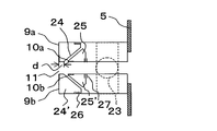
- a pair of pressurizing chambers 9a and 9b are provided above and below so as to sandwich the sealing chamber outer wall inlet 7.
- a pair of pressurizing chambers 9a and 9b are provided vertically so as to sandwich the seal chamber outer wall outlet 7 ′.
- the pressurizing chamber is a box-shaped chamber that is pressurized by supplying air outside the heat treatment apparatus.
- a single air supply duct 23 (having a branch pipe for supplying air to each pair of pressure chambers) shown in FIG. 2 is connected to all the upstream pressure chambers, and a common air supply path (not shown). Is connected to an air supply fan (not shown).
- another single supply duct is connected to all the downstream pressurizing chambers, and further connected to an air supply fan (not shown) via a common air supply path (not shown).
- air is explained as an example of the gas supplied to the pressurizing chamber (and the gas ejected from the nozzle of the air curtain means), particularly air outside the heat treatment apparatus, but a gas other than air can also be used. .
- the passage is located on the side opposite to the heat treatment chamber on the workpiece inlet side and outlet side of each seal chamber (the passage 19 is the inlet 7 side of the upstream seal chamber, and the passage 19 'is the downstream seal chamber. At the outlet 7 'side). More specifically, there is provided a passage 19 through which an object to be processed (precursor fiber bundle A) extends from the seal chamber outer wall inlet 7 toward the heat treatment apparatus inlet 11 further outward (upstream). In addition, a passage 19 ′ is provided which extends from the seal chamber outer wall outlet 7 ′ to the outside (downstream side) to the heat treatment apparatus outlet 11 ′ and through which the workpiece is passed.
- 19 is provided with a pair of rectangular nozzles for ejecting air toward the heat treatment apparatus inlet 11 and the passage 19 ′ toward the heat treatment apparatus outlet 11 ′), and the amount of gas ejection can be adjusted for each nozzle.
- a gas flow rate adjusting mechanism for example, a flow rate adjusting valve
- the heat treatment is performed toward the center in the vertical direction of the passage.
- a pair of slit-like nozzles 10a and 10b (nozzles for air curtain means) for ejecting air toward the opening of the apparatus inlet 11 are provided.
- the heat treatment is performed toward the center in the vertical direction of the passage.
- a pair of slit-like nozzles 10a 'and 10b' (nozzles for air curtain means) for ejecting air toward the opening of the apparatus delivery port 11 'are provided.
- the “nozzle” refers to a gas flow path (for example, an air path) having a rectangular cross section.
- Air curtain means 8 that suppresses inflow of outside air by blowing air outside the heat treatment apparatus to the outside (upstream side) of the seal chamber outer wall inlet 7 by the upstream pressurizing chambers 9a, 9b, nozzles 10a, 10b and the passage 19. (Upstream side) is configured. Further, the air curtain means 8 (downstream side) is formed on the outer side (downstream side) of the seal chamber outer wall outlet 7 ′ by the downstream pressurizing chambers 9a and 9b, the nozzles 10a ′ and 10b ′ and the passage 19 ′. .
- the nozzles 10a and 10b and 10a 'and 10b' extend in a direction perpendicular to the transfer direction of the workpiece (the depth direction in FIG. 1 and 2).
- the nozzle is parallel to the long side direction of the workpiece inlet and outlet of the passage and has a length equal to the length of the long side. That is, in each passage, the inlet and outlet of the passage are rectangular (the same rectangle as the cross section of the passage), and the long sides of the passage inlet and outlet (sides in the depth direction in FIG. 1) are parallel to each other, A nozzle (particularly the long side of the gas outlet of the nozzle) is arranged in parallel with these long sides.
- the long sides of the passage inlet and the outlet have the same length, and the long sides of the passage inlet and the outlet are equal to the length of the nozzle (particularly, the length of the long side of the gas ejection port of the nozzle).
- the heat treatment apparatus inlet 11 and the seal chamber outer wall inlet 7 are both rectangular (the same rectangle as the cross section of the passage 19), and the long sides of the inlet 11 and the inlet 7 are as follows. They are parallel to each other.
- the nozzles 10a and 10b (particularly, the long sides of the gas outlets of these nozzles) are both arranged in parallel to the long sides of the inlet 11 and the inlet 7.
- the long sides of the inlet 11 and the inlet 7 have the same length, and the lengths of the nozzles 10a and 10b (especially, the length of the long sides of the gas outlets of these nozzles) are both It is equal to the length of the long side of the inlet 7.
- the heat treatment apparatus inlet 11 is the heat treatment apparatus outlet 11 ′
- the seal chamber outer wall inlet 7 is the seal chamber outer wall outlet 7 ′
- the nozzle 10a and 10b are read as nozzles 10a ′ and 10b ′, respectively).
- the seal chamber has a negative pressure, and gas is ejected from the nozzle.
- the direction of the ejection is directed toward the center of the passage in the vertical direction and toward the heat treatment apparatus inlet or the heat treatment apparatus outlet located on the opposite side to the seal chamber of the workpiece inlet and outlet of the passage. It is. At this time, it is preferable that the gas is uniformly ejected over the length of the long side in parallel with the long side direction of the inlet and outlet of the workpiece in the passage.
- An ejection amount V (m 3 / h) of gas ejected from the nozzle per 1 m in the long side direction of the passage cross section and a pressure P (Pa) of the seal chamber connected to the passage are expressed by the following formula V ⁇ ⁇ 30 ⁇ P + 21 It is preferable to satisfy the condition because the amount of gas ejected from the nozzle can be reduced and the amount of gas flowing into the seal chamber can be controlled. Unless otherwise specified, the pressure is expressed as a gauge pressure. Strictly speaking, the unit is “m 3 / h / m”, but “m 3 / h” is used for simplicity. ing.
- the sealing chamber is set to a negative pressure, and the amount V (m 3 / h) of gas ejected from the nozzle per 1 m in the long side direction of the passage section is preferably 21 m 3 / h or more.
- the flow rate of the outside air flowing from the outside of the heat treatment apparatus into the heat treatment apparatus can be controlled uniformly in the long side direction of the passage.
- the ejection speed Vs of the gas ejected from the nozzle is preferably 3 m / s or more and 30 m / s or less. If the ejection speed Vs is 3 m / s or more, the flow rate of the outside air flowing from the outside to the inside of the heat treatment apparatus can be easily controlled uniformly in the long side direction of the passage. If the ejection speed Vs is 30 m / s or less, it becomes easy to reduce that a to-be-processed object flutters and quality falls by the friction between to-be-processed objects and the friction between apparatuses. From the viewpoint of cost reduction, the ejection speed Vs is preferably 15 m / s or less, more preferably 10 m / s or less, and even more preferably 5 m / s or less.
- the flow rate of the gas introduced from the passage into the seal chamber 4 is 0.1 m / second or more and 0.5 m / second or less. If the flow velocity of the introduced gas is 0.1 m / second or more, the flow rate of the outside air flowing from the outside of the heat treatment apparatus to the inside can be easily controlled uniformly in the long side direction of the passage, and 0.5 m / second or less. If it is, it will become easy to suppress the increase in the exhaust gas by external air inflow.
- each passage In each passage, the distance d between the gas outlets of the pair of nozzles and the opening (heat treatment apparatus inlet or heat treatment apparatus outlet) of the passage located on the opposite side of the seal chamber, and the passage height is Dn It is preferable that 2 ⁇ d ⁇ 0.75Dn is satisfied. When 2 ⁇ d ⁇ 0.75Dn is satisfied, it is easy to control the amount of gas flowing into the seal chamber even if the amount of gas ejected from the nozzle is reduced.
- the distance between the gas outlets of the pair of nozzles 10a and 10b on the side and the heat treatment apparatus inlet 11 and the distance between the gas outlet of the pair of nozzles 10a 'and 10b' on the downstream side and the heat treatment apparatus outlet 11 ' are as follows: 2 mm or more is preferable, 7 mm or more is more preferable, and 15 mm or more is still more preferable. Moreover, d ⁇ 0.73Dn is more preferable, and d ⁇ 0.70Dn is still more preferable.
- the distance between the heat treatment apparatus inlet 11 and the air outlet of the nozzle 10a is equal to the distance between the heat treatment apparatus inlet 11 and the air outlet of the nozzle 10b (this is preferable). But is not limited to this).
- the distance between the heat treatment apparatus delivery port 11 ′ and the air ejection port of the nozzle 10a ′ is equal to the distance between the heat treatment apparatus delivery port 11 ′ and the air ejection port of the nozzle 10b ′ (this) Is preferred, but not limited to this).
- the distance on the inlet side and the distance on the outlet side can be determined independently of each other.
- the height Dn of the passage is preferably 20 mm or more and 78 mm or less. If the passage height Dn is 20 mm or more, the object to be processed and the passage are less likely to come into contact with each other, and it is easy to reduce quality deterioration. If the passage height is 78 mm or less, it is easy to suppress the increase in equipment size and investment cost. .
- the opening width Wn of the nozzle is preferably 0.5 mm or more and 3 mm or less. If the opening width Wn is 0.5 mm or more, it is easy to ensure the nozzle clearance. If the opening width Wn is 3 mm or less, the nozzle ejection flow rate can be reduced and the ejection wind speed can be easily controlled.
- the nozzle opening width Wn is the width of the projected opening (in FIG. 4) when the nozzle opening is projected onto a plane perpendicular to the flow direction of the gas flowing in the nozzle. Length in a plane parallel to the paper surface).
- the pressurizing chambers 9 a and 9 b are pressurized by supplying air outside the heat treatment apparatus from the air supply duct 23.
- the nozzle 10 a provided in the pressurizing chamber 9 a of the air curtain means 8 is formed by an upper passage member (front member) 24 and an upper passage member (rear member) 25.
- the nozzle 10b provided in the pressurizing chamber 9b is formed by a lower passage member (front member) 24 ′ and a lower passage member (rear member) 25 ′.
- the passage through which the object to be processed fed from the heat treatment apparatus inlet 11 passes is formed by the upper passage member, the lower passage member, and the side member, and is sandwiched between the upper passage member and the lower passage member.
- Each of the upper and lower passage members separates the nozzle as shown in FIG. 3, and two members (a front member 24 and a rear member 25 for the upper passage member, a front member 24 ′ and a rear for the lower passage member). Member 25 ').
- the passage through which the workpiece sent out from the heat treatment apparatus delivery port 11 ′ passes is also formed by an upper passage member, a lower passage member, and a side member, and is formed by two upper and lower passage members. Sandwiched.
- the two members (the front member and the rear member) may be integrated (fixed) by a removable locking tool such as a bolt (not shown) with a spacer member 30 that determines a nozzle gap between the two members. it can.
- the manufacturing cost can be reduced by using such an assembly structure.
- the nozzle part can be disassembled, and maintenance work is facilitated.
- the front member is fixed to the air curtain means by a front member fixing rail 26 constituted by a plate extending in a direction perpendicular to the object to be processed (the depth direction in FIG. 2). Is done.
- a front member fixing rail 26 constituted by a plate extending in a direction perpendicular to the object to be processed (the depth direction in FIG. 2).
- two parallel plates extending in a direction perpendicular to the object to be processed (the depth direction in FIG. 2) are arranged. It is fixed to the air curtain means by a gap between the sheets.
- a plurality of precursor fiber bundles A are aligned in a direction perpendicular to the paper surface in the direction perpendicular to the paper surface, and the heat treatment device (from the uppermost heat treatment device inlet 11 of the seal chamber 4 on the left side of the heat treatment device 1 is shown. In particular, it is sent to the air curtain means 8) on the sending side.
- the precursor fiber bundle passes through the seal chamber outer wall inlet 7 of the outer wall 5 of the seal chamber 4 and the inlet 6 of the outer wall 3 of the heat treatment chamber 2, and is sent out from the outlet 6 ′ of the opposite outer wall 3 of the heat treatment chamber 2. Is done.
- the precursor fiber bundle A passes through the outlet 7 ′ of the outer wall 5 of the seal chamber 4 connected to the heat treatment chamber 2, passes through the air curtain means 8 (outlet side), and is sent to the outside of the heat treatment apparatus 1.
- the precursor fiber bundle A sent out to the outside of the heat treatment apparatus 1 is folded back so as to be wound around a roll 18 provided outside the heat treatment apparatus, and is sent from the feed inlet one below the feed outlet 7 ′. Then, it is again sent into the heat treatment apparatus 1.
- the precursor fiber bundle A fed into the heat treatment apparatus 1 again is sent to the outside of the heat treatment apparatus 1 through the same path in the opposite direction, and is wound again and folded back on the roll 18 outside the heat treatment apparatus 1.
- the precursor fiber bundle A is repeatedly fed back and out to the heat treatment apparatus 1 while being repeatedly folded outside the heat treatment apparatus 1 by the roll 18, and passes through the inside of the heat treatment apparatus 1 so as to meander.
- power is given to the precursor fiber bundle A by the rotation of the roll 18 and the friction on the surface of the roll 18, and the precursor fiber bundle A is continuously fed in the direction of the arrow X in FIG. 1.
- hot air circulates inside the heat treatment chamber 2 by a hot air circulation device (not shown), and is maintained at a temperature of 200 ° C. to 300 ° C., for example. Accordingly, the precursor fiber bundle A continuously fed repeatedly into the heat treatment chamber 2 is gradually heat-treated in the heat treatment chamber 2. At this time, a decomposition gas such as cyanide, ammonia, and carbon monoxide is generated in the heat treatment chamber 2 by the oxidation reaction of the precursor fiber bundle A.
- the gas in the heat treatment chamber is sent out by the exhaust fan 14, and recovered and processed by an external gas recovery processing device. Further, the adjustment of the exhaust amount of the generated decomposition gas from the exhaust port 20 provided in the heat treatment chamber 2 can be performed by a flow rate adjusting mechanism 13 such as a valve.
- the inside of the seal chambers 4 and 4 has a negative pressure by sucking the gas inside by the exhaust fans 17 and 17. Further, the heat treatment chamber 2 is heated to generate a vertical pressure distribution in which the upper part has a high pressure and the lower part has a low pressure.
- the pressure in each of the compartments 4 a, 4 b, 4 c of the seal chambers 4, 4 is changed according to the pressure distribution in the vertical direction in the heat treatment chamber 2 to the gas from the seal chambers 4, 4 into the heat treatment chamber 2.
- the air outside the heat treatment apparatus 1 is supplied to the upper and lower pressurizing chambers 9a and 9b of the air curtain means 8, and the nozzle 10a.
- the air curtain is formed by ejecting air from the nozzles 10a 'and 10b' to the outside of the seal chambers 4 and 4 toward the precursor fiber bundle A. At this time, air is ejected from the nozzles 10 a and 10 b toward the inlet 11. Further, air is ejected from the nozzles 10a 'and 10b' toward the delivery port 11 '.
- the distance between the nozzles 10a, 10b and the inlet 11 and the distance d (mm) between the nozzles 10a ', 10b' and the outlet 11 ' are preferably 2 ⁇ d ⁇ 50, more preferably 15 ⁇ d ⁇ 30.
- the distance d is within the above range, it is possible to reliably prevent the cracked gas from leaking from the seal chamber, and it is possible to reduce the amount of air blown out from the nozzle for ensuring the sealing performance.
- the distance between the nozzle 10a and the inlet 11, the distance between the nozzle 10b and the inlet 11, the distance between the nozzle 10a 'and the outlet 11', and the distance between the nozzle 10b 'and the outlet 11' are all. It shall be equal.
- the nozzle 10 a is formed by an upper passage member (front member) 24 and an upper passage member (rear member) 25.
- the nozzle 10b provided in the pressurizing chamber 9b is formed by a lower passage member (front member) 24 'and a lower passage member (rear member) 25'.
- each of the upper and lower passage members is formed of two members with the nozzles therebetween.
- the two members can be integrated (fixed) by a detachable locking tool such as a bolt (not shown) with a spacer member 30 that determines the nozzle gap between the two members. This is because the manufacturing cost can be reduced and the nozzle portion can be easily cleaned and maintained.
- the air that is uniformly distributed in the upper and lower directions is ejected from the upper and lower jet outlets at the tips of the nozzles 10a and 10b at a substantially equal jet velocity Vs to form an air curtain that collides with the precursor fiber bundle A from above and below.
- the present invention it is possible to reduce the amount of air blown out from the nozzle for ensuring the sealing performance, and it is possible to reduce the load of the air blowing means on the air curtain seal device.
- the carbon fiber precursor fiber bundle can be heat-treated with the horizontal heat treatment apparatus described above to produce a flame-resistant fiber bundle.
- a carbon fiber bundle can be produced by producing a flame resistant fiber bundle by such a method for producing a flame resistant fiber bundle and carbonizing the obtained flame resistant fiber bundle.
- the optimal air curtain structure was derived by performing simulations under various conditions using analysis software.
- the analysis method uses numerical fluid analysis (CFD method), and analysis software includes GAMBIT (trade name. Ansys Japan Co., Ltd. for mesh and shape creation) and FLUENT (trade name. Ansys Japan Co., Ltd. for analysis). Using.
- CFD method numerical fluid analysis
- analysis software includes GAMBIT (trade name. Ansys Japan Co., Ltd. for mesh and shape creation) and FLUENT (trade name. Ansys Japan Co., Ltd. for analysis).
- the simulation was performed at a calculation time of about 3 hours / CASE with the number of meshes being about 1.5 million meshes.
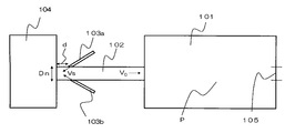
- FIG. 7 is a diagram for explaining the model used here.
- an air curtain passage (flow passage simulating an air curtain passage) 102 is connected to a seal chamber (box simulating a seal chamber) 101, and this passage is an area outside the heat treatment apparatus (an area simulating the outside). ) 104.
- Air curtain nozzles (flow channels simulating nozzles) 103a and 103b are provided at the upper and lower portions of the passage 102, respectively. The angle ⁇ with respect to the horizontal plane of the nozzle was 30 °.
- a heat treatment chamber inlet 105 is provided on the side of the seal chamber 101 opposite to the passage 102.
- the gas was air
- the reference pressure was 101325 Pa (atmospheric pressure) in absolute pressure
- the air temperature was 25 ° C.
- the outflow conditions to the outside of the heat treatment apparatus were free outflow.
- the distance between the heat treatment apparatus inlet 11 and the gas outlets of the nozzles 10a and 10b (in the model, the distance between the opening of the passage 102 to the outside of the heat treatment apparatus and the gas outlets of the nozzles 103a and b) d is 2 to 70mm
- passage height (height of passage 102 in the model) Dn is 10 to 80mm
- nozzle opening width (opening width of nozzles 103a and b in the model) Wn is changed in the range of 0.5 to 5mm Carried out.
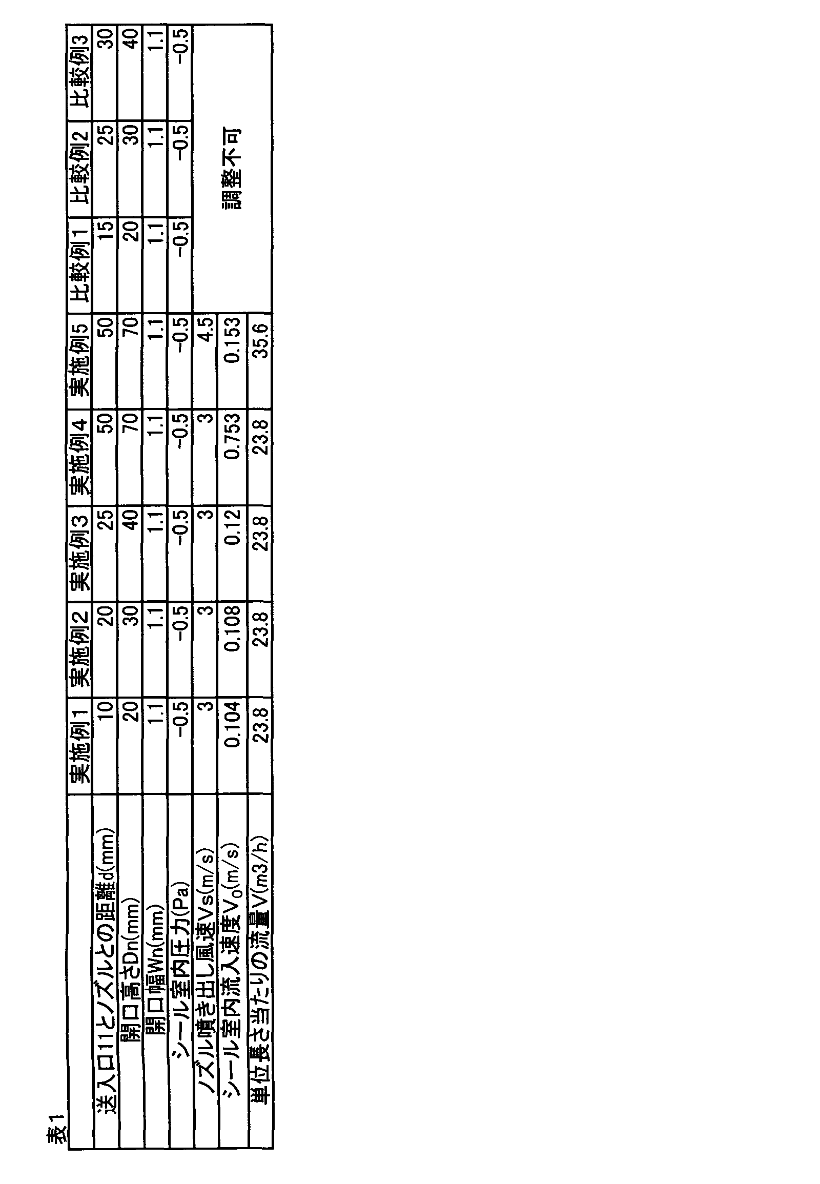
- Example 1 The distance d is set to 10 mm, the passage height Dn is set to 20 mm, the nozzle opening width Wn is set to 1.1 mm, the pressure P in the seal chamber is set to ⁇ 0.5 Pa, and the gas blowing speed Vs from the gas outlet of the nozzle is set to 3 m / s.
- the gas inflow velocity Vo into the seal chamber was calculated.
- Table 1 shows the conditions and the inflow speed in the seal chamber. In Tables 1, 2, and 4, the distance d is displayed as “distance between the inlet 11 and the nozzle”, and the passage height Dn is displayed as “opening height”.
- Example 2 Calculation was performed in the same manner as in Example 1 except that the distance d was 20 mm and the passage height Dn was 30 mm.
- Example 3 Calculation was performed in the same manner as in Example 1 except that the distance d was 25 mm and the passage height Dn was 40 mm.
- Example 4 Calculation was performed in the same manner as in Example 1 except that the distance d was 50 mm and the passage height Dn was 70 mm.
- Example 5 Calculation was performed in the same manner as in Example 4 except that the nozzle ejection wind speed Vs was set to 4.5 m / s.
- Example 1 The calculation was performed in the same manner as in Example 1 except that the distance d was 15 mm and the passage height Dn was 20 mm. At this time, it was confirmed that the air inflow speed into the seal chamber could not be controlled to 0.1 m / s or more, or gas blowing from the seal chamber to the outside of the heat treatment apparatus was confirmed. In the embodiment, there was no such balloon.
- Comparative Example 2 Calculation was performed in the same manner as in Example 1 except that the distance d was 25 mm and the passage height Dn was 30 mm. As in Comparative Example 1, the air inflow speed into the seal chamber could not be controlled to 0.1 m / s or more, or blowing was confirmed.
- Comparative Example 3 The calculation was performed in the same manner as in Example 1 except that the distance d was 30 mm and the passage height Dn was 40 mm. As in Comparative Example 1, the air inflow speed into the seal chamber could not be controlled to 0.1 m / s or more, or blowing was confirmed.
- Example 6 When the distance d is 20 mm, the passage height Dn is 30 mm, the nozzle opening width Wn is 1.1 mm, and the pressure P in the seal chamber is ⁇ 2, ⁇ 5, and ⁇ 10 Pa, respectively, the gas inflow rate into the seal chamber Vo becomes 0.2 m / s, and the gas ejection speed Vs (m / s) from the gas ejection port of the nozzle so as not to eject gas from the passage to the outside of the heat treatment apparatus, and per 1 m in the width direction of the workpiece.
- the gas ejection flow rate V (m 3 / h) from the nozzle was calculated.
- Example 7 Calculation was performed in the same manner as in Example 6 except that the passage height Dn was 40 mm.
- Example 8 Calculation was performed in the same manner as in Example 6 except that the passage height Dn was set to 70 mm.
- Example 9 Calculation was performed in the same manner as in Example 6 except that the passage height Dn was 80 mm.
- Example 10 Calculation was performed in the same manner as in Example 7 except that the nozzle opening width Wn was 0.5 mm.
- Example 11 Calculation was performed in the same manner as in Example 7 except that the nozzle opening width Wn was set to 2 mm.
- Example 12 Calculation was performed in the same manner as in Example 7 except that the nozzle opening width Wn was 3 mm.
- Example 13 Calculation was performed in the same manner as in Example 7 except that the nozzle opening width Wn was set to 4 mm.
- Example 14 Calculation was performed in the same manner as in Example 7 except that the nozzle opening width Wn was set to 5 mm.
- a test apparatus 100 having a schematic structure without the heat treatment chamber 2 shown in FIG. Vs, the distance d between the gas outlets of the nozzles 10a and 10b and the heat treatment device inlet 11, and the gas inflow velocity Vo from the seal chamber outer wall inlet 7 to the seal chamber were measured.
- the openings of the nozzles 10a and 10b had an opening length of 2000 mm (length in the drawing depth direction) and an opening width Wn of 1.1 mm.
- Whether the gas flows into the seal chamber 4 from the seal chamber outer wall inlet 7 or the gas flows out of the seal chamber through the inlet 7 is determined by using a smoke tester manufactured by GASTECH, Inc. Observed and confirmed.
- the nozzle ejection speed Vs was measured using an Anemo Master 6071 anemometer (trade name) manufactured by Kanomax.
- the amount of exhaust from the exhaust fan 17 and the amount of inflow from the inlet 6 are measured using an anemone master 6071 anemometer (trade name) manufactured by Kanomax. It was calculated from the difference.
- the pressure in the seal chamber 4 was measured using a Manostar gauge fine differential pressure gauge manufactured by Yamamoto Electric Co., Ltd.
- the air ejected from the gas ejection ports of the nozzles 10a and 10b of the air curtain means 8 is supplied from an air supply fan (not shown).
- Vs of the air curtain means 8 the pressure inside the seal chamber was made negative by the exhaust fan 17, and the internal pressure of the seal chamber 4 was measured by manostar gauges installed at two locations on the front side and the back side of the paper. .
- the distance d between the gas ejection ports of the nozzles 10a and 10b and the heat treatment apparatus inlet 11 is further adjusted according to the ejection speed Vs of the air ejected from the gas ejection ports of the nozzles 10a and 10b.
- Example 15 Similar to the above-described experiment, the test apparatus 100 having a schematic structure shown in FIG. 4 was used in this experiment.
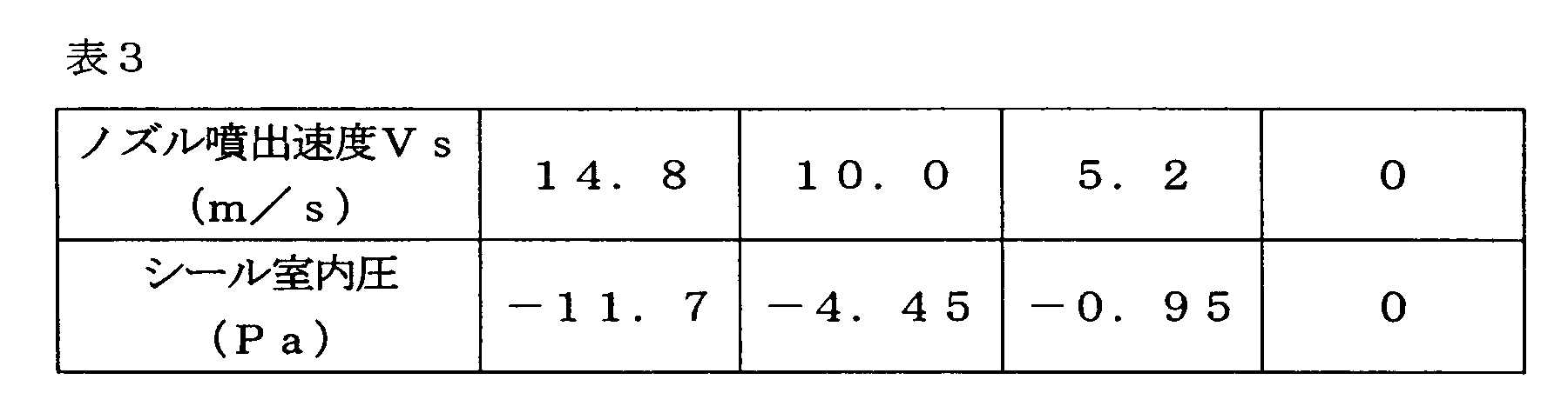
- the nozzle jet velocity Vs was set to three conditions of 5.2, 9.96, and 14.8 m / s.
- Smoke tester is used at the seal chamber outer wall inlet 7 under each nozzle jet velocity condition, the direction of smoke flow is observed, and the outflow of gas from the seal chamber 4 over the entire width in the furnace width direction (from the front side to the back side).
- the exhaust fan 17 was adjusted so that there was no occurrence, and the internal pressure of the seal chamber 4 was measured with a manostar gauge.
- Dn is 40 mm
- Wn is 1.1 mm
- the heat treatment chamber outer wall inlet 6 and the seal chamber outer wall inlet 7 are 2000 mm in length
- the nozzle opening is 2000 mm in length
- the horizontal plane of the nozzle The angles ⁇ were all 30 °.
- Example 16 The measurement was performed in the same manner as in Example 15 except that the distance d between the gas ejection ports of the nozzles 10a and 10b and the heat treatment apparatus inlet 11 was set to 5 mm.
- Example 17 Measurement was performed in the same manner as in Example 15 except that the distance d was set to 10 mm.
- Example 18 Measurement was performed in the same manner as in Example 15 except that the distance d was set to 15 mm.
- Example 19 Measurement was performed in the same manner as in Example 15 except that the distance d was set to 20 mm.
- Example 20 Measurement was performed in the same manner as in Example 15 except that the distance d was set to 25 mm.
- Example 21 Measurement was performed in the same manner as in Example 15 except that Dn was set to 30 mm and the distance d was set to 20 mm.
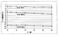
- Table 4 shows the results of Examples 15 to 21 and Comparative Examples 6 and 7. The results of Examples 15 to 20 and Comparative Example 6 are shown in FIG.
- the nozzle ejection wind speed Vs is set to three conditions of 5.2, 9.96, and 14.8 m / s, and the distance d between the gas ejection ports of the nozzles 10 a and 10 b and the heat treatment apparatus inlet 11 is adjusted.
- the target line of the gas inflow velocity Vo 0.2 m / s (the direction perpendicular to the transfer direction of the workpiece) Represents the relationship between the pressure in the seal chamber and the distance d, which can achieve the limit gas inflow speed necessary to ensure that no gas is blown out in the furnace.
- the seal chamber pressure when adjusted to a target gas inflow speed of approximately 0.2 m / s at the same nozzle jet velocity is reduced by increasing d.
- the pressure in the seal chamber is the same, the outside air inflow speed can be adjusted with a smaller nozzle jet velocity by increasing d.
- the nozzle ejection wind speed necessary for adjusting the gas inflow speed is increased.
- the sealing pressure when adjusted to a target gas inflow velocity of 0.2 m / s at the same nozzle ejection wind speed decreases as d increases in the range of 2 mm or more, and d is 15 mm or more. This tendency is more noticeable in the range of.
- the precursor fiber bundle can be transferred in one stage to several tens of stages in the vertical direction depending on the situation.
Landscapes
- Engineering & Computer Science (AREA)
- Mechanical Engineering (AREA)
- General Engineering & Computer Science (AREA)
- Textile Engineering (AREA)
- Manufacturing & Machinery (AREA)
- Chemical & Material Sciences (AREA)
- Chemical Kinetics & Catalysis (AREA)
- General Chemical & Material Sciences (AREA)
- Inorganic Fibers (AREA)
- Tunnel Furnaces (AREA)
- Furnace Details (AREA)
- Treatment Of Fiber Materials (AREA)
Description
連続した扁平状の被処理物を熱処理室内で水平方向に移送させながら連続的に熱処理する横型熱処理装置であって、
熱処理室の被処理物送入口と送出口とに、それぞれ、排気ファンが接続されたシール室が連接され、前記シール室は、被処理物がシール室を水平方向に通過可能に構成され、
各シール室の被処理物送入口および送出口のうちの熱処理室と反対側に位置する開口に、断面が矩形状である通路が連接され、前記通路は、被処理物が通路を水平方向に通過可能に構成され、
シール室被処理物送入口に連接された通路の被処理物送入口が、前記熱処理装置の被処理物送入口であり、かつ、シール室被処理物送出口に連接された通路の被処理物送出口が、前記熱処理装置の被処理物送出口であり、
各通路の上下の位置に、気体を噴出する一対のノズルが設けられ、
各ノズルの気体噴出口は矩形状であり、
各通路において、この通路に設けられた一対のノズルは、この通路の上下方向の中心に向かって、かつ、この通路が有する熱処理装置の被処理物送入口もしくは被処理物送出口に向かって気体を噴出し、
各通路において、この通路に設けられた各ノズルの気体噴出口は、この通路の被処理物の送入口および送出口の長辺方向と平行であり、かつ、前記長辺の長さと等しい長さを有し、かつ、
各通路において、この通路に設けられた一対のノズルの気体噴出口と、この通路が有する熱処理装置の被処理物送入口もしくは被処理物送出口との間の距離dと、この通路の高さDnとが
2≦d<0.75Dn
を満たす
横型熱処理装置が提供される。
前記シール室は、各通路に対応して区画されていることができる。
上側および下側の通路部材のそれぞれが、ノズルを隔てて、二つの部材を有し、
前記二つの部材が、これら二つの部材の間にノズル間隙を決めるスペーサー部材を挟んで一体化されることができる。
炭素繊維前駆体繊維束を横型熱処理装置で熱処理して、耐炎化繊維束を製造する、耐炎化繊維束の製造方法であって、
前記横型熱処理装置が、連続した扁平状の被処理物を熱処理室内で水平方向に移送させながら連続的に熱処理する横型熱処理装置であり、
熱処理室の被処理物送入口と送出口とに、それぞれ、排気ファンが接続されたシール室が連接され、前記シール室は、被処理物がシール室を水平方向に通過可能に構成され、
各シール室の被処理物送入口および送出口のうちの熱処理室と反対側に位置する開口に、断面が矩形状である通路が連接され、前記通路は、被処理物が通路を水平方向に通過可能に構成され、
シール室被処理物送入口に連接された通路の被処理物送入口が、前記熱処理装置の被処理物送入口であり、かつ、シール室被処理物送出口に連接された通路の被処理物送出口が、前記熱処理装置の被処理物送出口であり、
各通路の上下の位置に、気体を噴出する一対のノズルが設けられ、
各ノズルの気体噴出口は矩形状であり、
各通路において、この通路に設けられた一対のノズルは、この通路の上下方向の中心に向かって、かつ、この通路が有する熱処理装置の被処理物送入口もしくは被処理物送出口に向かって気体を噴出し、
各通路において、この通路に設けられた各ノズルの気体噴出口は、この通路の被処理物の送入口および送出口の長辺方向と平行であり、かつ、前記長辺の長さと等しい長さを有し、かつ、
各通路において、この通路に設けられた一対のノズルの気体噴出口と、この通路が有する熱処理装置の被処理物送入口もしくは被処理物送出口との間の距離dと、この通路の高さDnとが
2≦d<0.75Dn
を満たす
横型熱処理装置であり;かつ、
- 前記排気ファンを用いて各シール室を負圧にすること、
- 各通路において、この通路に設けられた各ノズルの、この通路の被処理物の送入口および送出口の長辺1m当たりの気体噴出量をV(m3/h)と表し、この通路に連接されたシール室内のゲージ圧をP(Pa)と表したとき、
V≦-30×P+21
が満たされるように、各ノズルから気体を噴出させること、
を含む、耐炎化繊維束の製造方法が提供される。
上述の耐炎化繊維束の製造方法によって耐炎化繊維束を製造する工程、および、前記耐炎化繊維束を炭素化する工程、を有する炭素繊維束の製造方法が提供される。
上述の横型熱処理装置を用いて、連続した扁平状の被処理物を連続的に熱処理する熱処理方法が提供される。
熱処理室2の上流側および下流側(図示左右両側)の外壁(互いに対向する二つの側壁)3,3には、炉内で発生した分解ガスが熱処理装置の前駆体繊維束の送入/送出口から熱処理装置外に漏出することを防止するために、室内を負圧にし、分解ガスを回収するシール室4,4がそれぞれ連設されている。シール室は箱形とすることができる。
シール室外壁送入口7を挟むように上下に一対の加圧室9a,9bが設けられている。また、シール室外壁送出口7’を挟むように上下に一対の加圧室9a,9bが設けられている。加圧室は、熱処理装置外の空気が供給されることで加圧される箱型の室である。全ての上流側加圧室に図2に示す単一の給気ダクト23(加圧室の各対に給気するための分岐管を有する)が接続され、さらに共通給気路(図示しない)を介して給気ファン(図示しない)に接続されている。また、全ての下流側加圧室においても別の単一の供給ダクトが接続され、さらに共通給気路(図示しない)を介して給気ファン(図示しない)に接続されている。なお、ここでは加圧室に供給する気体(およびエアーカーテン手段のノズルから噴出させる気体)として空気、特には熱処理装置外の空気を例にして説明するが、空気以外の気体を用いることもできる。
V≦-30×P+21
を満たすことが、ノズルから噴出す気体の噴出量を減らして、シール室への気体流入量を制御することができるので好ましい。なお、特に断りのない限り圧力はゲージ圧で表す。気体噴出量Vは、通路断面の長辺方向1mあたりの噴出量であるため、厳密にはその単位は「m3/h/m」であるが、簡単のため「m3/h」を用いている。
各通路において、一対のノズルの気体噴出口と、シール室と反対側に位置するその通路の開口(熱処理装置送入口または熱処理装置送出口)との間の距離dとし、通路高さをDnとしたとき、2≦d<0.75Dnが満足されることが好ましい。2≦d<0.75Dnを満たすと、ノズルから噴出す気体の噴出量を少なくしても、シール室への気体流入量を制御することが容易である。具体的には、シール室内からのガス(例えば分解ガス)の漏出を防止する観点から、また、外部から流入する気体を抑制し、気体噴出口から噴出する気体の量を低減する観点から、上流側の一対のノズル10a,10bの気体噴出口と熱処理装置送入口11との距離、及び、下流側の一対のノズル10a’,10b’の気体噴出口と熱処理装置送出口11’との距離は、それぞれ、2mm以上が好ましく、7mm以上がより好ましく、15mm以上が更に好ましい。また、d<0.73Dnがより好ましく、d<0.70Dnが更に好ましい。なおここでは、熱処理装置送入口11とノズル10aの空気噴出口との間の距離と、熱処理装置送入口11とノズル10bの空気噴出口との間の距離は、等しいものとする(これは好ましいが、これに限定はされない)。また、熱処理装置送出口11’とノズル10a’の空気噴出口との間の距離と、熱処理装置送出口11’とノズル10b’の空気噴出口との間の距離は、等しいものとする(これは好ましいが、これに限定はされない)。送入口側の距離と、送出口側の距離は、互いに独立して決めることができる。
図2において、加圧室9a,9bは給気ダクト23から熱処理装置外の空気が供給されることで加圧される。また、エアーカーテン手段8の加圧室9aに設けられたノズル10aは上側通路部材(前部材)24と上側通路部材(後部材)25によって形成される。同様に加圧室9bに設けられたノズル10bは下側通路部材(前部材)24’と下側通路部材(後部材)25’によって形成される。
距離dを10mmとし、通路高さDnを20mmとし、ノズル開口幅Wnを1.1mmとし、シール室内圧力Pを-0.5Pa、ノズルの気体噴出口からの気体噴き出し風速Vsを3m/sとし、シール室内への気体流入速度Voを計算した。各条件およびシール室内流入速度を表1に示す。なお、表1、2および4においては、前記距離dは「送入口11とノズルとの距離」と表示され、前記通路高さDnは「開口高さ」と表示されている。
距離dを20mmとし、通路高さDnを30mmとした以外は実施例1と同様にして計算した。
距離dを25mmとし、通路高さDnを40mmとした以外は実施例1と同様にして計算した。
距離dを50mmとし、通路高さDnを70mmとした以外は実施例1と同様にして計算した。
ノズル噴き出し風速Vsを4.5m/sとした以外は実施例4と同様にして計算した。
距離dを15mmとし、通路高さDnを20mmとした以外は実施例1と同様にして計算した。この時、シール室内への空気流入速度を0.1m/s以上に制御できない、またはシール室内から熱処理装置外部への気体吹き出しが確認された。実施例ではこのような吹き出しは無かった。
距離dを25mmとし、通路高さDnを30mmとした以外は実施例1と同様にして計算した。比較例1同様、シール室内への空気流入速度を0.1m/s以上に制御できない、または吹き出しが確認された。
距離dを30mmとし、通路高さDnを40mmとした以外は実施例1と同様にして計算した。比較例1同様、シール室内への空気流入速度を0.1m/s以上に制御できない、または吹き出しが確認された。
距離dを20mmとし、通路高さDnを30mmとし、ノズル開口幅Wnを1.1mmとし、シール室内の圧力Pをそれぞれ-2、-5、-10Paとした時、シール室内への気体流入速度Voが0.2m/sとなり、通路から熱処理装置の外部に気体が噴出さないようにノズルの気体噴出口からの気体噴き出し速度Vs(m/s)と、被処理物の幅方向1m当たりのノズルからの気体噴き出し流量V(m3/h)を計算した。
通路高さDnを40mmとした以外は実施例6と同様にして計算した。
通路高さDnを70mmとした以外は実施例6と同様にして計算した。
通路高さDnを80mmとした以外は実施例6と同様にして計算した。
ノズル開口幅Wnを0.5mmとした以外は実施例7と同様にして計算した。
ノズル開口幅Wnを2mmとした以外は実施例7と同様にして計算した。
ノズル開口幅Wnを3mmとした以外は実施例7と同様にして計算した。
ノズル開口幅Wnを4mmとした以外は実施例7と同様にして計算した。
ノズル開口幅Wnを5mmとした以外は実施例7と同様にして計算した。
通路高さDnを10mmとした以外は実施例6と同様にして計算した。シール室内圧力-2、-5、-10Paではノズルの気体噴出口からの気体噴き出し速度Vs(m/s)を調整し、シール室内への気体流入速度Voが0.2m/sと通路から熱処理装置の外部に気体が噴出さないようにできたが、シール室内圧力-0.5Paと圧力を更に小さくした場合は熱処理装置の外部に気体が噴出することが想定される。
通路高さDnを20mmとした以外は実施例6と同様にして計算した。シール室内圧力-2、-5、-10Paではノズルの気体噴出口からの気体噴き出し速度Vs(m/s)を調整し、シール室内への気体流入速度Voが0.2m/sと通路から熱処理装置の外部に気体が噴出さないようにできたが、シール室内圧力-0.5Paと圧力を更に小さくした場合は熱処理装置の外部に気体が噴出することが想定される。

前述の実験と同様、本実験では、図4に示す模式的な構造の試験装置100を用いた。ノズル10aの気体噴出口と熱処理装置送入口11との距離,ノズル10bの気体噴出口と熱処理装置送入口11との距離をいずれも2mmとし(d=2mm)、ノズルへの給気量を変えることによりノズル噴出風速Vsを5.2、9.96、14.8m/sの3条件に設定した。各ノズル噴出風速条件で、シール室外壁送入口7においてスモークテスターを用い、煙の流れる方向を観察し、炉幅方向(紙面手前側から紙面奥側)まで全幅においてシール室4からの気体の流出がないよう、排気ファン17を調整し、シール室4の内圧をマノスターゲージにて測定した。前述の実験と同様に、Dnは40mm、Wnは1.1mm、熱処理室外壁送入口6、シール室外壁送入口7の開口長さは2000mm、ノズル開口部の開口長さも2000mm、ノズルの水平面に対する角度θはいずれも30°とした。
ノズル10a,10bの気体噴出口と熱処理装置送入口11との距離dを5mmとした以外は実施例15と同様にして測定した。
距離dを10mmとした以外は実施例15と同様にして測定した。
距離dを15mmとした以外は実施例15と同様にして測定した。
距離dを20mmとした以外は実施例15と同様にして測定した。
距離dを25mmとした以外は実施例15と同様にして測定した。
Dnを30mm、距離dを20mmとした以外は実施例15と同様にして測定した。
距離dを0mmとした以外は実施例15と同様にして測定した。この時、ノズルを製作する際、距離dを0mmの位置にノズルの噴き出し口を設ける場合は加工が難しく、このため距離dを2mm以上に設定する。
距離dを30mmとした以外は実施例15と同様にして測定した。この時、ノズル吹き出し風速(Vs)5.2m/sにおいてシール室内圧-1.35Pa、シール室内への気体流入速度(Vo)を0.2m/sに設定したところ、送入口7の一部から吹き出しが確認された。実施例ではこのような吹き出しは無かった。この例は、d<0.75Dnが満たされない場合(この例ではd=0.75Dnである)、被処理物の移送方向に直角な方向にて炉内ガスの吹き出しが確認される箇所が生じ、シール室4の気体が送入口7から熱処理装置1の外部へ漏出することを示している。

2:熱処理室
3:熱処理室外壁
4:シール室
5:シール室の外壁
6:熱処理室外壁の送入口
6’:熱処理室外壁の送出口
7:シール室外壁送入口
7’:シール室外壁送出口
8:エアーカーテン手段
9a、9b:加圧室(上側および下側)
10a、10b:送入側エアーカーテン用ノズル(上側および下側)
10a’、10b’:送出側エアーカーテン用ノズル(上側および下側)
11:熱処理装置送入口
11’:熱処理装置送出口
12:仕切り板
13:流量調節機構
14:排気ファン
15:排気口
16:流量調節機構
17:排気ファン
18:ロール
19:送入側エアーカーテン手段の通路
19’:送出側エアーカーテン手段の通路
20:排気孔
21:排気路
22:排気路
23:給気ダクト
24:上側通路部材(前部材)
25:上側通路部材(後部材)
24’:下側通路部材(前部材)
25’:下側通路部材(後部材)
26:前部材固定用レール
27:後部材固定用レール
30:スペーサー部材
31:実施例で用いた距離d調節用部材
100:実施例で用いた試験装置
101:シール室
102:エアーカーテンの通路
103:エアーカーテンのノズル
104:熱処理装置外部
105:熱処理室入口
P:シール室内圧力
Vs:ノズルからの気体噴き出し風速
Vo:シール室内への気体流入速度
A:前駆体繊維束(束)
X:前駆体繊維束の移送方向
d:ノズル10a、10bと送入口11の距離
Dn:エアーカーテン手段の通路の開口高さ
Wn:ノズルの開口幅
θ:ノズルの水平面に対する傾斜角度
Claims (13)
- 連続した扁平状の被処理物を熱処理室内で水平方向に移送させながら連続的に熱処理する横型熱処理装置であって、
熱処理室の被処理物送入口と送出口とに、それぞれ、排気ファンが接続されたシール室が連接され、前記シール室は、被処理物がシール室を水平方向に通過可能に構成され、
各シール室の被処理物送入口および送出口のうちの熱処理室と反対側に位置する開口に、断面が矩形状である通路が連接され、前記通路は、被処理物が通路を水平方向に通過可能に構成され、
シール室被処理物送入口に連接された通路の被処理物送入口が、前記熱処理装置の被処理物送入口であり、かつ、シール室被処理物送出口に連接された通路の被処理物送出口が、前記熱処理装置の被処理物送出口であり、
各通路の上下の位置に、気体を噴出する一対のノズルが設けられ、
各ノズルの気体噴出口は矩形状であり、
各通路において、この通路に設けられた一対のノズルは、この通路の上下方向の中心に向かって、かつ、この通路が有する熱処理装置の被処理物送入口もしくは被処理物送出口に向かって気体を噴出し、
各通路において、この通路に設けられた各ノズルの気体噴出口は、この通路の被処理物の送入口および送出口の長辺方向と平行であり、かつ、前記長辺の長さと等しい長さを有し、かつ、
各通路において、この通路に設けられた一対のノズルの気体噴出口と、この通路が有する熱処理装置の被処理物送入口もしくは被処理物送出口との間の距離dと、この通路の高さDnとが
2≦d<0.75Dn
を満たす
横型熱処理装置。 - 各通路において、前記距離dが、15mm以上である請求項1に記載の横型熱処理装置。
- 各通路において、前記ノズルの開口幅Wnが0.5mm以上3mm以下であり、前記通路の高さDnが20mm以上78mm以下である請求項1または2に記載の横型熱処理装置。
- 鉛直方向の複数の位置においてそれぞれ被処理物を水平方向に移送可能なように、鉛直方向の複数の位置にそれぞれ前記通路が設けられ、
前記シール室は、各通路に対応して区画されている請求項1~3のいずれか一項に記載の横型熱処理装置。 - 前記ノズル毎に気体の噴出し量が調節可能な気体流量調節機構を有する請求項1~4のいずれか一項に記載の横型熱処理装置。
- 前記通路が、上側の通路部材と下側の通路部材と側面部材によって形成され、
上側および下側の通路部材のそれぞれが、ノズルを隔てて、二つの部材を有し、
前記二つの部材が、これら二つの部材の間にノズル間隙を決めるスペーサー部材を挟んで一体化された請求項1~5のいずれか一項に記載の横型熱処理装置。 - 前記二つの部材および前記スペーサー部材が着脱自在な請求項1~6のいずれかに記載の横型熱処理装置。
- 炭素繊維前駆体繊維束を熱処理する熱処理炉である請求項1~7のいずれかに記載の横型熱処理装置。
- 炭素繊維前駆体繊維束を横型熱処理装置で熱処理して、耐炎化繊維束を製造する、耐炎化繊維束の製造方法であって、
前記横型熱処理装置が、連続した扁平状の被処理物を熱処理室内で水平方向に移送させながら連続的に熱処理する横型熱処理装置であり、
熱処理室の被処理物送入口と送出口とに、それぞれ、排気ファンが接続されたシール室が連接され、前記シール室は、被処理物がシール室を水平方向に通過可能に構成され、
各シール室の被処理物送入口および送出口のうちの熱処理室と反対側に位置する開口に、断面が矩形状である通路が連接され、前記通路は、被処理物が通路を水平方向に通過可能に構成され、
シール室被処理物送入口に連接された通路の被処理物送入口が、前記熱処理装置の被処理物送入口であり、かつ、シール室被処理物送出口に連接された通路の被処理物送出口が、前記熱処理装置の被処理物送出口であり、
各通路の上下の位置に、気体を噴出する一対のノズルが設けられ、
各ノズルの気体噴出口は矩形状であり、
各通路において、この通路に設けられた一対のノズルは、この通路の上下方向の中心に向かって、かつ、この通路が有する熱処理装置の被処理物送入口もしくは被処理物送出口に向かって気体を噴出し、
各通路において、この通路に設けられた各ノズルの気体噴出口は、この通路の被処理物の送入口および送出口の長辺方向と平行であり、かつ、前記長辺の長さと等しい長さを有し、かつ、
各通路において、この通路に設けられた一対のノズルの気体噴出口と、この通路が有する熱処理装置の被処理物送入口もしくは被処理物送出口との間の距離dと、この通路の高さDnとが
2≦d<0.75Dn
を満たす
横型熱処理装置であり;かつ、
- 前記排気ファンを用いて各シール室を負圧にすること、
- 各通路において、この通路に設けられた各ノズルの、この通路の被処理物の送入口および送出口の長辺1m当たりの気体噴出量をV(m3/h)と表し、この通路に連接されたシール室内のゲージ圧をP(Pa)と表したとき、
V≦-30×P+21
が満たされるように、各ノズルから気体を噴出させること、
を含む、耐炎化繊維束の製造方法。 - 各通路からシール室に流入する気体の流速Voを、0.1m/秒以上0.5m/秒以下にする請求項9に記載の耐炎化繊維束の製造方法。
- 各ノズルから噴出する気体の噴出速度Vsを、3m/s以上30m/s以下にする請求項9または10に記載の耐炎化繊維束の製造方法。
- 請求項9~11のいずれか一項に記載の耐炎化繊維束の製造方法によって耐炎化繊維束を製造する工程、および、前記耐炎化繊維束を炭素化する工程、を有する炭素繊維束の製造方法。
- 請求項1~8のいずれか一項に記載の横型熱処理装置を用いて、連続した扁平状の被処理物を連続的に熱処理する熱処理方法。
Priority Applications (5)
| Application Number | Priority Date | Filing Date | Title |
|---|---|---|---|
| CN201380008381.1A CN104093892B (zh) | 2012-02-07 | 2013-02-07 | 卧式热处理装置 |
| JP2013508315A JP5578276B2 (ja) | 2012-02-07 | 2013-02-07 | 横型熱処理装置 |
| KR1020147019687A KR101552127B1 (ko) | 2012-02-07 | 2013-02-07 | 횡형 열처리장치 |
| US14/376,979 US10132008B2 (en) | 2012-02-07 | 2013-02-07 | Horizontal heat treatment device |
| EP13747001.9A EP2813603B1 (en) | 2012-02-07 | 2013-02-07 | Horizontal heat treatment device |
Applications Claiming Priority (2)
| Application Number | Priority Date | Filing Date | Title |
|---|---|---|---|
| JP2012024137 | 2012-02-07 | ||
| JP2012-024137 | 2012-02-07 |
Publications (1)
| Publication Number | Publication Date |
|---|---|
| WO2013118826A1 true WO2013118826A1 (ja) | 2013-08-15 |
Family
ID=48947583
Family Applications (1)
| Application Number | Title | Priority Date | Filing Date |
|---|---|---|---|
| PCT/JP2013/052883 Ceased WO2013118826A1 (ja) | 2012-02-07 | 2013-02-07 | 横型熱処理装置 |
Country Status (8)
| Country | Link |
|---|---|
| US (1) | US10132008B2 (ja) |
| EP (1) | EP2813603B1 (ja) |
| JP (1) | JP5578276B2 (ja) |
| KR (1) | KR101552127B1 (ja) |
| CN (1) | CN104093892B (ja) |
| HU (1) | HUE029934T2 (ja) |
| TW (1) | TWI516739B (ja) |
| WO (1) | WO2013118826A1 (ja) |
Families Citing this family (12)
| Publication number | Priority date | Publication date | Assignee | Title |
|---|---|---|---|---|
| US9388494B2 (en) | 2012-06-25 | 2016-07-12 | Novellus Systems, Inc. | Suppression of parasitic deposition in a substrate processing system by suppressing precursor flow and plasma outside of substrate region |
| JP5728554B2 (ja) * | 2013-10-18 | 2015-06-03 | ユニ・チャーム株式会社 | 不織布の嵩回復装置、及び、不織布の嵩回復方法 |
| US9617638B2 (en) | 2014-07-30 | 2017-04-11 | Lam Research Corporation | Methods and apparatuses for showerhead backside parasitic plasma suppression in a secondary purge enabled ALD system |
| US10676847B2 (en) | 2014-11-07 | 2020-06-09 | Illinois Tool Works Inc. | Discharge nozzle plate for center-to-ends fiber oxidation oven |
| US9508547B1 (en) * | 2015-08-17 | 2016-11-29 | Lam Research Corporation | Composition-matched curtain gas mixtures for edge uniformity modulation in large-volume ALD reactors |
| US9738977B1 (en) | 2016-06-17 | 2017-08-22 | Lam Research Corporation | Showerhead curtain gas method and system for film profile modulation |
| CN106637516B (zh) * | 2016-12-21 | 2019-04-02 | 湖南顶立科技有限公司 | 预氧化炉热风循环系统 |
| CA3078394C (en) | 2017-10-10 | 2025-02-11 | Deakin University | PRECURSOR STABILIZATION METHOD |
| CN107955999B (zh) * | 2017-12-11 | 2020-07-14 | 湖南顶立科技有限公司 | 一种碳化硅纤维裂解室和碳化硅纤维裂解系统 |
| JP7166089B2 (ja) * | 2018-06-29 | 2022-11-07 | 東京エレクトロン株式会社 | 基板処理装置、基板処理システムおよび基板処理方法 |
| KR102935543B1 (ko) | 2019-07-17 | 2026-03-05 | 램 리써치 코포레이션 | 기판 프로세싱을 위한 산화 프로파일의 변조 |
| CN112899823B (zh) * | 2021-01-18 | 2023-03-10 | 安徽天鹏新材料科技有限公司 | 一种石墨烯碳纤维的预氧设备及预氧方法 |
Citations (5)
| Publication number | Priority date | Publication date | Assignee | Title |
|---|---|---|---|---|
| US6027337A (en) | 1998-05-29 | 2000-02-22 | C.A. Litzler Co., Inc. | Oxidation oven |
| WO2002077337A1 (en) | 2001-03-26 | 2002-10-03 | Toho Tenax Co., Ltd. | Flame resistant rendering heat treating device, and operation method for the device |
| JP2007224432A (ja) * | 2006-02-21 | 2007-09-06 | Mitsubishi Rayon Co Ltd | 横型熱処理装置及び熱処理方法 |
| JP2008081859A (ja) * | 2006-09-26 | 2008-04-10 | Mitsubishi Rayon Co Ltd | 横型耐炎化炉および耐炎化処理方法 |
| JP2008156790A (ja) | 2006-12-25 | 2008-07-10 | Mitsubishi Rayon Co Ltd | 熱処理装置および熱処理方法 |
Family Cites Families (4)
| Publication number | Priority date | Publication date | Assignee | Title |
|---|---|---|---|---|
| JP4377007B2 (ja) * | 1999-09-30 | 2009-12-02 | 三菱レイヨン株式会社 | 炭素繊維の製造方法 |
| CN2913998Y (zh) * | 2006-05-23 | 2007-06-20 | 连云港鹰游纺机有限责任公司 | 叠层式外热预氧化炉 |
| JP5162351B2 (ja) * | 2008-06-27 | 2013-03-13 | 三菱レイヨン株式会社 | 炭素繊維製造用炭化炉のシール装置 |
| CN102782418B (zh) * | 2010-01-29 | 2015-02-11 | 利兹勒有限公司 | 氧化炉的端面密封部件 |
-
2013
- 2013-02-07 US US14/376,979 patent/US10132008B2/en active Active
- 2013-02-07 JP JP2013508315A patent/JP5578276B2/ja active Active
- 2013-02-07 EP EP13747001.9A patent/EP2813603B1/en active Active
- 2013-02-07 KR KR1020147019687A patent/KR101552127B1/ko active Active
- 2013-02-07 WO PCT/JP2013/052883 patent/WO2013118826A1/ja not_active Ceased
- 2013-02-07 TW TW102104946A patent/TWI516739B/zh active
- 2013-02-07 CN CN201380008381.1A patent/CN104093892B/zh active Active
- 2013-02-07 HU HUE13747001A patent/HUE029934T2/en unknown
Patent Citations (5)
| Publication number | Priority date | Publication date | Assignee | Title |
|---|---|---|---|---|
| US6027337A (en) | 1998-05-29 | 2000-02-22 | C.A. Litzler Co., Inc. | Oxidation oven |
| WO2002077337A1 (en) | 2001-03-26 | 2002-10-03 | Toho Tenax Co., Ltd. | Flame resistant rendering heat treating device, and operation method for the device |
| JP2007224432A (ja) * | 2006-02-21 | 2007-09-06 | Mitsubishi Rayon Co Ltd | 横型熱処理装置及び熱処理方法 |
| JP2008081859A (ja) * | 2006-09-26 | 2008-04-10 | Mitsubishi Rayon Co Ltd | 横型耐炎化炉および耐炎化処理方法 |
| JP2008156790A (ja) | 2006-12-25 | 2008-07-10 | Mitsubishi Rayon Co Ltd | 熱処理装置および熱処理方法 |
Non-Patent Citations (1)
| Title |
|---|
| See also references of EP2813603A4 * |
Also Published As
| Publication number | Publication date |
|---|---|
| TW201344136A (zh) | 2013-11-01 |
| US10132008B2 (en) | 2018-11-20 |
| TWI516739B (zh) | 2016-01-11 |
| JPWO2013118826A1 (ja) | 2015-05-11 |
| US20150299909A1 (en) | 2015-10-22 |
| KR101552127B1 (ko) | 2015-09-10 |
| EP2813603A1 (en) | 2014-12-17 |
| KR20140103167A (ko) | 2014-08-25 |
| CN104093892B (zh) | 2016-03-16 |
| JP5578276B2 (ja) | 2014-08-27 |
| EP2813603B1 (en) | 2016-05-18 |
| CN104093892A (zh) | 2014-10-08 |
| HUE029934T2 (en) | 2017-04-28 |
| EP2813603A4 (en) | 2015-03-25 |
Similar Documents
| Publication | Publication Date | Title |
|---|---|---|
| JP5578276B2 (ja) | 横型熱処理装置 | |
| CN111372753B (zh) | 用于膜拉伸设备的通风模块和这样的膜拉伸设备 | |
| CN107429441B (zh) | 用于中心到端部的纤维氧化炉的排放喷嘴板 | |
| EP3778034B1 (en) | Gas blowout nozzle and furnace, and method for manufacturing processed film | |
| CN111448046B (zh) | 膜制造装置 | |
| WO2014156977A1 (ja) | テンターオーブンおよび熱可塑性樹脂フィルムの製造方法 | |
| JP4838700B2 (ja) | 熱処理装置および熱処理方法 | |
| JP6295760B2 (ja) | テンターオーブンおよび熱可塑性樹脂フィルムの製造方法 | |
| JP4796467B2 (ja) | 横型耐炎化炉および耐炎化処理方法 | |
| CN102399973B (zh) | 一种热处理用汽雾冷却装置 | |
| CN107438678B (zh) | 用于中心到端部的纤维氧化炉的改进的供应气室 | |
| CN107849811B (zh) | 用于空气承载的连续纸张干燥的喷嘴箱 | |
| JP2007224432A (ja) | 横型熱処理装置及び熱処理方法 | |
| WO2019097713A1 (ja) | 金属板の冷却装置及び金属板の連続熱処理設備 | |
| KR100640134B1 (ko) | 편평 제품과의 열교환용 장치 및 편평 제품용 냉각 장치 | |
| EP3538695A1 (en) | Ovens comprising discharge nozzle plate for distribution of gas through the oven, and method to operate an oven | |
| WO2023171213A1 (ja) | 吹出しノズル | |
| KR20220031664A (ko) | 이동 스트립의 표면 상에 가스를 취입하기 위한 냉각 장치 |
Legal Events
| Date | Code | Title | Description |
|---|---|---|---|
| WWE | Wipo information: entry into national phase |
Ref document number: 201380008381.1 Country of ref document: CN |
|
| ENP | Entry into the national phase |
Ref document number: 2013508315 Country of ref document: JP Kind code of ref document: A |
|
| 121 | Ep: the epo has been informed by wipo that ep was designated in this application |
Ref document number: 13747001 Country of ref document: EP Kind code of ref document: A1 |
|
| ENP | Entry into the national phase |
Ref document number: 20147019687 Country of ref document: KR Kind code of ref document: A |
|
| WWE | Wipo information: entry into national phase |
Ref document number: 2013747001 Country of ref document: EP |
|
| WWE | Wipo information: entry into national phase |
Ref document number: 14376979 Country of ref document: US |
|
| NENP | Non-entry into the national phase |
Ref country code: DE |