WO2013121494A1 - 光ファイバ心線、光ファイバテープ心線および光ケーブル - Google Patents
光ファイバ心線、光ファイバテープ心線および光ケーブル Download PDFInfo
- Publication number
- WO2013121494A1 WO2013121494A1 PCT/JP2012/008037 JP2012008037W WO2013121494A1 WO 2013121494 A1 WO2013121494 A1 WO 2013121494A1 JP 2012008037 W JP2012008037 W JP 2012008037W WO 2013121494 A1 WO2013121494 A1 WO 2013121494A1
- Authority
- WO
- WIPO (PCT)
- Prior art keywords
- coating layer
- optical fiber
- primary coating
- core wire
- water
- Prior art date
- Legal status (The legal status is an assumption and is not a legal conclusion. Google has not performed a legal analysis and makes no representation as to the accuracy of the status listed.)
- Ceased
Links
Images

Classifications
-
- G—PHYSICS
- G02—OPTICS
- G02B—OPTICAL ELEMENTS, SYSTEMS OR APPARATUS
- G02B6/00—Light guides; Structural details of arrangements comprising light guides and other optical elements, e.g. couplings
- G02B6/44—Mechanical structures for providing tensile strength and external protection for fibres, e.g. optical transmission cables
- G02B6/4401—Optical cables
- G02B6/4429—Means specially adapted for strengthening or protecting the cables
- G02B6/44384—Means specially adapted for strengthening or protecting the cables the means comprising water blocking or hydrophobic materials
-
- G—PHYSICS
- G02—OPTICS
- G02B—OPTICAL ELEMENTS, SYSTEMS OR APPARATUS
- G02B6/00—Light guides; Structural details of arrangements comprising light guides and other optical elements, e.g. couplings
- G02B6/02—Optical fibres with cladding with or without a coating
- G02B6/02395—Glass optical fibre with a protective coating, e.g. two layer polymer coating deposited directly on a silica cladding surface during fibre manufacture
-
- G—PHYSICS
- G02—OPTICS
- G02B—OPTICAL ELEMENTS, SYSTEMS OR APPARATUS
- G02B6/00—Light guides; Structural details of arrangements comprising light guides and other optical elements, e.g. couplings
- G02B6/44—Mechanical structures for providing tensile strength and external protection for fibres, e.g. optical transmission cables
- G02B6/4401—Optical cables
- G02B6/4403—Optical cables with ribbon structure
- G02B6/4404—Multi-podded
Definitions
- the present invention relates to an optical fiber core wire, an optical fiber tape core wire, and an optical cable excellent in water resistance.
- An exemplary optical fiber core used in such an optical fiber includes a glass fiber, a primary coating layer coated on the outer periphery of the glass fiber, and a secondary coating layer coated on the outer periphery of the primary coating layer. And a colored layer coated on the outer periphery of the secondary coating layer.
- Patent Document 1 a material used for a primary coating layer of an optical fiber core wire is coated on a glass plate and immersed in warm water, and then the material is peeled off at an angle of 90 degrees from the glass plate. Measure the peel force when It is disclosed that the use of a material adjusted so that the peeling force has a predetermined value as the primary coating layer suppresses the generation of large water bubbles during immersion in warm water and reduces the increase in transmission loss.
- Patent Document 2 discloses that by adjusting the glass transition temperatures of the primary coating layer and the secondary coating layer of the optical fiber core wire to predetermined values, generation of large water bubbles during hot water immersion is suppressed. It is disclosed that an increase in transmission loss is reduced.
- the present inventor has intensively researched that the distribution of water bubbles formed in the primary coating layer during water immersion is non-uniform, resulting in an increase in transmission loss and separation of the interface between the glass fiber and the primary coating layer. I found a new cause. Therefore, in the present invention, rather than suppressing the formation of water bubbles in the primary coating layer at the time of water immersion, rather than improving the water resistance by uniformly forming water bubbles in the primary coating layer, Takes a different approach.
- the object of the present invention is to generate water bubbles uniformly in the primary coating layer during water immersion, thereby suppressing the separation of the interface between the glass fiber and the primary coating layer and reducing the increase in transmission loss. It is providing the optical fiber core wire excellent in property.
- the optical fiber core wire 100 includes an optical fiber including a glass fiber 101, a primary coating layer 102 coated on the outer periphery of the glass fiber 101, and a secondary coating layer 103 coated on the outer periphery of the primary coating layer 102.
- a strand 100a and a colored layer 104 coated on the outer periphery of the optical fiber strand 100a are provided.
- the primary coating layer 102 becomes a soft buffer layer, and the secondary coating layer 103 functions as a hard protective layer, thereby increasing transmission loss even when an external force is applied to the optical fiber 100a. Can be suppressed.
- the elastic modulus of the primary coating layer 102 is 0.2 to 3 MPa
- the elastic modulus of the secondary coating layer 103 is 500 to 1200 MPa
- the elasticity of the colored layer 104 is The rate is preferably 100 to 2000 MPa.
- the coating material of the colored layer 104 is colored with a dye or a pigment for visual recognition.
- the colored layer 104 is not necessarily colored, and may be a non-colored tertiary coating layer for maintaining strength or the like.
- the primary coating layer 102 or the secondary coating layer 103 is colored with a dye or a pigment and the colored layer 104 is not provided is becoming widespread.
- the collective coating layer used to form an optical fiber tape core by arranging a plurality of optical fiber cores in parallel and coating them together acts as a tertiary coating layer. To do.
- this invention presupposes the structure by which the tertiary coating layer whose elasticity modulus is 100 Mpa or more is coat
- the colored layer acts as a semipermeable membrane, and osmotic pressure is generated due to a difference in the concentration of the aqueous solution at the delamination portion and the water outside the color layer, and water is further separated from the delamination portion. Delamination may grow by moving to. Therefore, especially in an optical fiber having a colored layer, the transmission loss may be remarkably increased.
- the glass fiber 101 has a diameter of 90 to 150 ⁇ m, preferably about 125 ⁇ m, and the primary coating layer 102 and the secondary coating layer 103 each have a thickness of 10 to 60 ⁇ m, preferably 20 to 50 ⁇ m. The thickness is 5 to 20 ⁇ m.
- the size of each layer is not limited to these values and can be arbitrarily changed.
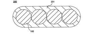
- a plurality of optical fiber core wires 100 may be combined into a tape shape.
- a schematic diagram of the optical fiber ribbon 200 thus configured is shown in FIG.
- the optical fiber ribbon 200 has a configuration in which a batch coating layer 201 covers the outside of a plurality of optical fibers 100 arranged in parallel.
- the elastic modulus of the collective coating layer 201 is preferably 100 to 2000 MPa from the viewpoint of maintaining the strength.
- the size of the optical fiber ribbon 200 is about 320 ⁇ m thick and about 1.1 mm wide.
- the size of the optical fiber ribbon 200 and the number of the optical fibers 100 are not limited to these values and can be arbitrarily changed.
- an optical fiber 100a may be used instead of the optical fiber 100.
- the outer side of the secondary coating layer 103 of the optical fiber 100a is configured to cover the collective coating layer 201 as a tertiary coating layer.
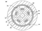
- the optical fiber cable 300 is, for example, a 40-core SZ cable.
- the optical fiber cable 300 includes a spacer 301 having a five-groove SZ slot 302. In each SZ slot 302, two optical fiber ribbons 200 are accommodated.
- a presser winding tape 303 is wound around the spacer 301, and the outer side of the presser winding tape 303 is covered with a sheath 304.
- a tension member 305 is provided at the center of the cross section of the spacer 301.
- a tracer mark 306 is provided on the outer periphery of the spacer 301, and a tear string 307 is provided on a part of the outer periphery of the presser winding tape 303.
- the SZ slot 302 is not limited to the five-groove type, and the number of grooves can be selected as appropriate. Further, the number of the optical fiber ribbons 200 in the SZ slot 302 is not limited to two, and the number can be selected as appropriate. Further, an S slot may be used instead of the SZ slot.
- An elastic modulus (also called Young's modulus) is used as an index representing the hardness of each coating layer.
- the elastic modulus is measured for each coating layer after fabrication of the optical fiber.
- a specific method for measuring the elastic modulus a known method may be used.
- the limit adhesion is an index representing the adhesion at the interface between the glass fiber and the primary coating layer under wet heat.
- the limit adhesion is defined as follows. Note that the definition of the limit adhesion is based on the description in Patent Document 3.
- An optical fiber core wire is prepared by cutting all the circumference of the coating layer so as to leave only the glass fiber at a position 10 mm away from one end, and the coating layer in the range of 10 mm from the one end of the optical fiber core wire is bonded. Fix to sandpaper with agent. In an atmosphere of a temperature of 60 ° C.
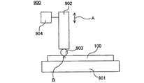
- the load test apparatus 900 includes a stage 901 on which the optical fiber 100 to be measured is placed, a load portion 902 that can adjust the magnitude of a load that is provided apart from the stage 901, and a load portion 902.
- the rod 903 is provided so as to be perpendicular to the longitudinal direction of the optical fiber core 100 placed on the stage 901 and parallel to the surface of the stage 901.
- the rod 903 and the stage 901 sandwich the optical fiber core wire 100, and the load portion 902 applies a load to one point B on the optical fiber core wire 100. Thereafter, when a predetermined time elapses, the drive unit 904 moves the load unit 902 and the rod 903 away from the optical fiber core wire 100, and the load unit 902 does not apply a load to the optical fiber core wire 100.
- the start and end of load application may be controlled by the user's hand, or may be performed automatically by providing a control unit. Any measuring device may be used as long as a predetermined load can be applied to one point B of the optical fiber core 100 from a direction perpendicular to the longitudinal direction of the optical fiber core for a predetermined time.
- the optical fiber core wire 100 to be measured is fixed to the load test apparatus 900. Then, a predetermined load is applied at a certain point for 4.5 seconds, and the load is repeatedly applied to 30 points at intervals of about 6 mm. Thereafter, using an optical microscope, the presence or absence of delamination or tear at each point is observed. Further, the load is increased, and each time the load application and observation at 30 points different from the previous observation are repeated. This creates a plot of load magnitude versus delamination or number of tears. Note that the number of points to which the load is applied is not limited to 30. The minimum load when delamination or tear is observed at 50% or more of the total number of points to which the load is applied is defined as D50 and T50, respectively.
- the elastic modulus of the primary coating layer In order to make delamination difficult to occur (that is, to increase D50), it is only necessary to lower the elastic modulus of the primary coating layer and increase the elastic modulus of the secondary coating layer to alleviate the external force transmitted to the glass primary interface. .
- an additive such as a silane coupling agent may be added to the primary coating layer material to increase the adhesion between the surface of the glass fiber and the primary coating layer.
- the elastic modulus of the primary coating layer may be lowered, that is, the crosslinking density of the primary coating layer may be lowered.
- a hydrophobic oligomer such as polytetramethylene glycol (PTMG) is used as a primary coating layer material to prevent local water bubbles from being generated, and acrylamide
- PTMG polytetramethylene glycol
- the water absorption can be adjusted by adding a hydrophilic monomer such as. Therefore, the material of each coating layer is adjusted so that D50 and T50 become predetermined values, and the mixing ratio of the hydrophobic substance and hydrophilic substance of the primary coating layer material is adjusted so that water bubbles are evenly distributed.
- Examples 1 to 4 and Comparative Examples 1 to 3 are prepared, which are optical fiber tapes having the configuration shown in FIG. 2 and are optical fiber tapes having various properties of each coating layer.
- the optical fiber core wire was taken out from the fiber tape core wire, and the above-mentioned elastic modulus, D50, T50, and critical adhesion were measured.
- the transmission loss before warm water immersion was measured using the optical fiber ribbon.
- the observation of the water bubble and the measurement of the transmission loss were performed. The results are shown in Table 1.
- the presence / absence of delamination was determined to be present if at least one delamination of the glass primary interface occurred at any of the six observation locations, and absent if none occurred.
- the largest number of micro bubbles represents the number of the most observed water bubbles among the six observation points. Further, the minimum number of microbubbles represents the smallest number of water bubbles observed among the six observation locations. When the number of water bubbles is more than 10, “> 10” is indicated.
- the maximum diameter of the microbubbles represents the diameter of the largest water bubble among the six observation points. When the shape of the water bubbles is elliptical, the longest distance passing through the center of the water bubbles is defined as the diameter of the water bubbles. When the diameter of the water bubbles is larger than 10 ⁇ m, “> 10” is indicated.
Landscapes
- Physics & Mathematics (AREA)
- General Physics & Mathematics (AREA)
- Optics & Photonics (AREA)
- Optical Fibers, Optical Fiber Cores, And Optical Fiber Bundles (AREA)
- Surface Treatment Of Glass Fibres Or Filaments (AREA)
Abstract
Description
このような構成を有する光ファイバ心線が、水中、特に温水中に長期間浸漬されると、1次被覆層中に水泡が発生し、ガラスファイバと1次被覆層との間の界面(ガラスプライマリ界面ともいう)に剥離が起こり、その結果浸水前に比べて伝送ロスが増加する問題が発生する場合があることが知られている。
また、特許文献2には、光ファイバ心線の1次被覆層および2次被覆層のガラス転移温度がそれぞれ所定の値となるように調整することによって、温水浸漬時に大きな水泡の発生が抑制され、伝送ロス増が低減されることが開示されている。
本発明の目的は、浸水時に1次被覆層中に一様に水泡を生成させることによって、ガラスファイバと1次被覆層との間の界面の剥離を抑制し、伝送ロス増を低減できる、耐水性に優れた光ファイバ心線を提供することである。
図1に、本実施形態に係る光ファイバ心線100の概略図を示す。すなわち、光ファイバ心線100は、ガラスファイバ101と、ガラスファイバ101の外周に被覆された1次被覆層102と、1次被覆層102の外周に被覆された2次被覆層103からなる光ファイバ素線100aと、光ファイバ素線100aの外周に被覆された着色層104とを備える。
ここで、1次被覆層102の弾性率は低く、2次被覆層103の弾性率は高くなるように、各層の被覆材料を調整することが望ましい。これにより、1次被覆層102が軟質のバッファ層となり、2次被覆層103が硬質の保護層として機能することによって、光ファイバ素線100aに外力が加えられた場合においても、伝送ロス増加を抑制することができる。具体的には、光ファイバとしての機能を保持するためには、1次被覆層102の弾性率は0.2~3MPa、2次被覆層103の弾性率は500~1200MPa、着色層104の弾性率は100~2000MPaとすることが好ましい。
着色層104の被覆材料は、視認のために染料または顔料で着色される。しかしながら、着色層104は必ずしも着色されている必要はなく、強度維持等のための着色されていない3次被覆層であっても構わない。
なお、ガラスファイバと1次被覆層の間の剥離部分に溜まった水には、被覆層中の可溶成分が溶け出し水溶液となる。2次被覆層の外側に着色層があると、着色層が半透膜として作用し、層間剥離部分の水溶液と着色層外部の水の濃度差により浸透圧が発生し、更に水が層間剥離部分に移動してくることで層間剥離が成長することがある。
したがって、着色層を有する光ファイバ心線においては、特に伝送ロスが著しく増加する場合がある。
なお、光ファイバテープ心線200を構成するために、光ファイバ心線100の代わりに、光ファイバ素線100aを用いてもよい。その場合には、光ファイバ素線100aの2次被覆層103の外側を、3次被覆層として一括被覆層201が覆う構成となる。
上記SZスロット302は、5溝のタイプに限定されるものではなく、溝数は適宜選択することができる。さらにSZスロット302内の光ファイバテープ心線200の本数も、2本に限定されず、その本数は適宜選択することができる。また、SZスロットに代えてSスロットを用いてもよい。
各被覆層の硬さを表す指標として、弾性率(ヤング率ともいう)を用いる。弾性率は、光ファイバの作製後に各被覆層に対して測定される。弾性率の具体的な測定手法としては、周知のものを用いてよい。
限界密着力は、湿熱下でのガラスファイバと1次被覆層との間の界面の密着力を表す指標である。限界密着力は以下のように定義される。なお、限界密着力の定義は、特許文献3の記載に基づいている。
一端から10mm離れた位置においてガラスファイバのみを残すよう被覆層の全周に渡って切り込みを入れた光ファイバ心線を用意し、該光ファイバ心線の該一端から10mmの範囲の被覆層を接着剤でサンドペーパーに固定する。温度60℃、湿度98%RHの雰囲気下で、該光ファイバ心線の該一端が上になるように該サンドペーパーを固定し、該光ファイバ心線の他端に錘を取り付ける。これにより、切り込みより上の長さ10mmの部分のガラスファイバと1次被覆層との間に一定荷重が与えられる。この状態でガラスファイバが1次被覆層から抜けるまでの時間を測定する。そして、ガラスファイバに与える荷重、すなわち、錘の質量を徐々に変えてガラスファイバが抜けるまでの時間との関係を求める。
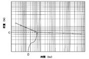
図4には、限界密着力の典型的な測定結果の例を示す。図4は限界密着力の定義の理解を助けるための例として示す図であるため、本実施例の実施結果を表しているものではなく、縦軸および横軸の具体的な数値は省略されていることを理解されたい。図4によれば、ガラスファイバと1次被覆層との間に加える荷重を小さくするにつれて、1次被覆層からガラスファイバが抜けるまでの時間が長くなっていく。しかしながら、ある荷重C以下になるとガラスファイバが抜けるまでの時間が急激に長くなり傾きが緩くなる。このように、ガラスファイバが抜けるまでの時間が急激に長くなり傾きが緩くなる変曲点Dが存在する。この傾きが緩くなる変曲点Dにおける荷重Cを、限界密着力と定義する。特許文献3には、この限界密着力が大きいほど、温水浸漬後の伝送ロス増が低減されることが示されている。
本明細書において、ガラスプライマリ界面が剥離することをデラミネーションと呼び、1次被覆層の内部が裂けること、または空隙ができることをテアーと呼ぶ。デラミネーションの起こりやすさ、およびテアーの起こりやすさは、ガラスプライマリ界面の剥離の起こりやすさ、および水泡のできやすさに関連すると考えられる。デラミネーションの起こりやすさ、およびテアーの起こりやすさの定量的な指標として、それぞれD50およびT50を以下のように定義する。
デラミネーションおよびテアーの測定装置の一例として、荷重試験装置900の概略図を図5に示す。荷重試験装置900は、測定対象の光ファイバ心線100を載置するためのステージ901と、ステージ901から離間して設けられている荷重の大きさを調整可能な荷重部902と、荷重部902のステージ901側に固定されているロッド903と、荷重部902およびロッド903をステージ901の法線方向Aに沿って移動させることが可能な駆動部904とを備える。ロッド903は、ステージ901に載置された状態の光ファイバ心線100の長手方向に垂直であって、ステージ901の表面に平行になるように設けられている。
駆動部904が荷重部902を解放すると、荷重部902およびロッド903が自重によりステージ901の方へ移動する。ロッド903とステージ901は光ファイバ心線100を挟み込み、荷重部902は光ファイバ心線100上の一点Bに荷重を与える。その後、所定の時間が経過すると、駆動部904は、荷重部902およびロッド903を光ファイバ心線100から離れる方向に移動させ、荷重部902は荷重を光ファイバ心線100に与えなくなる。
なお、荷重付与の開始と終了をユーザの手で制御してもよく、制御部を設けて自動で行ってもよい。測定装置としては光ファイバ心線100の一点Bに、該光ファイバ心線の長手方向の垂直方向から所定の荷重を所定の時間与えられるものであればよく、図5の装置構成に限定されない。
荷重が与えられた全地点数の50%以上においてデラミネーションまたはテアーが観察される場合の最低荷重を、それぞれD50、T50と定義する。つまり、該プロットにおいて、荷重を与えられた30箇所のうち、50%(15箇所)以上の地点でデラミネーションが観察される場合の最低荷重をD50とする。また、該プロットにおいて、荷重を与えられた30箇所のうち、50%(15箇所)以上の地点でテアーが観察される場合の最低荷重をD50とする。
D50が低いほど、デラミネーションを起こすために必要な荷重が小さい、つまりデラミネーションが起こりやすいといえる。同様に、T50が低いほど、テアーを起こすために必要な荷重が小さい、つまりテアーが起こりやすいといえる。したがって、D50およびT50は、それぞれデラミネーションおよびテアーの起こりやすさの指標として用いることができるのである。
なお、この測定方法は、非特許文献1に記載の方法に基づいている。
特許文献1および2に示されているように、従来、浸水時に1次被覆層中に水泡が発生すること自体が伝送ロス増の原因であると考えられてきた。それに対して、本発明者は鋭意研究した結果、浸水時に1次被覆層中に形成される水泡の分布が不均一であることが、ガラスファイバと1次被覆層との間の界面の剥離および伝送ロス増の一因となっていることを新たに見出した。
浸水により、1次被覆層中に水泡が生成されない、または不均一に生成される場合には、2次被覆層からの応力がガラスプライマリ界面にそのまま、または一部の領域に集中して伝わるため、剥離が発生しやすいと考えられる。一方で、浸水により1次被覆層中に均一に水泡が生成されると、一様に分布した水泡により2次被覆層からの応力が緩和され、その結果、ガラスプライマリ界面の剥離が抑制されると考えられる。
したがって、浸水時に発生する水泡の数を低減しなくとも、水泡が1次被覆層中に均一に生成されるように光ファイバ心線の材料を調整することによって、ガラスプライマリ界面に均一な力が加わり、その結果、剥離の抑制および伝送ロスの低減を実現できるのである。
本発明者は、デラミネーションよりもテアーを起こりやすくすることによって、温水浸漬時に1次被覆層中に均一の水泡が生成され、伝送ロス増が低減できることを見出した。デラミネーションよりもテアーが起こりやすい、つまりD50がT50より大きいと、温水浸漬時に2次被覆層からの応力が起因となってデラミネーションより先に1次被覆層内部に水泡が形成される。その結果、応力が該水泡により緩和されるため、伝送ロス増を低減できるものと考えられる。
デラミネーションを起こりにくくする(つまり、D50を上げる)には、1次被覆層の弾性率を低くし、2次被覆層の弾性率を高くして、ガラスプライマリ界面に伝わる外力を緩和すればよい。または、1次被覆層材料に、例えばシランカップリング剤のような添加剤を加えてガラスファイバの表面と1次被覆層との密着力を上げればよい。
テアーを起りやすくする(つまり、T50を下げる)には、1次被覆層の弾性率を下げる、つまり1次被覆層の架橋密度を下げればよい。
さらに、1次被覆層中に均一に水泡を分布させるために、1次被覆層材料として、ポリテトラメチレングリコール(PTMG)等の疎水性のオリゴマーを用いて局所的な水泡ができることを防ぎ、アクリルアミド等の親水性のモノマーを加えて吸水率を調整することができる。
したがって、D50およびT50が所定の値になるように各被覆層の材料を調整することと、均一に水泡を分布させるように1次被覆層材料の疎水性物質および親水性物質の混合割合を調整することと総合的に行うことによって、温水浸漬時に1次被覆層中に均一に水泡を生成される光ファイバ心線を得ることができる。
図2に示す構成を有する光ファイバテープ心線であって、各被覆層の性質を様々に変えた光ファイバテープ心線である実施例1~4および比較例1~3を用意し、その光ファイバテープ心線から光ファイバ心線を取り出して上述の弾性率、D50、T50、限界密着力の測定を行った。また、光ファイバテープ心線を用いて温水浸漬前の伝送ロスの測定を行った。
また、各実施例および比較例を200日間、60℃の温水に浸漬した後、水泡の観察と伝送ロスの測定を行った。その実施結果を表1に示す。
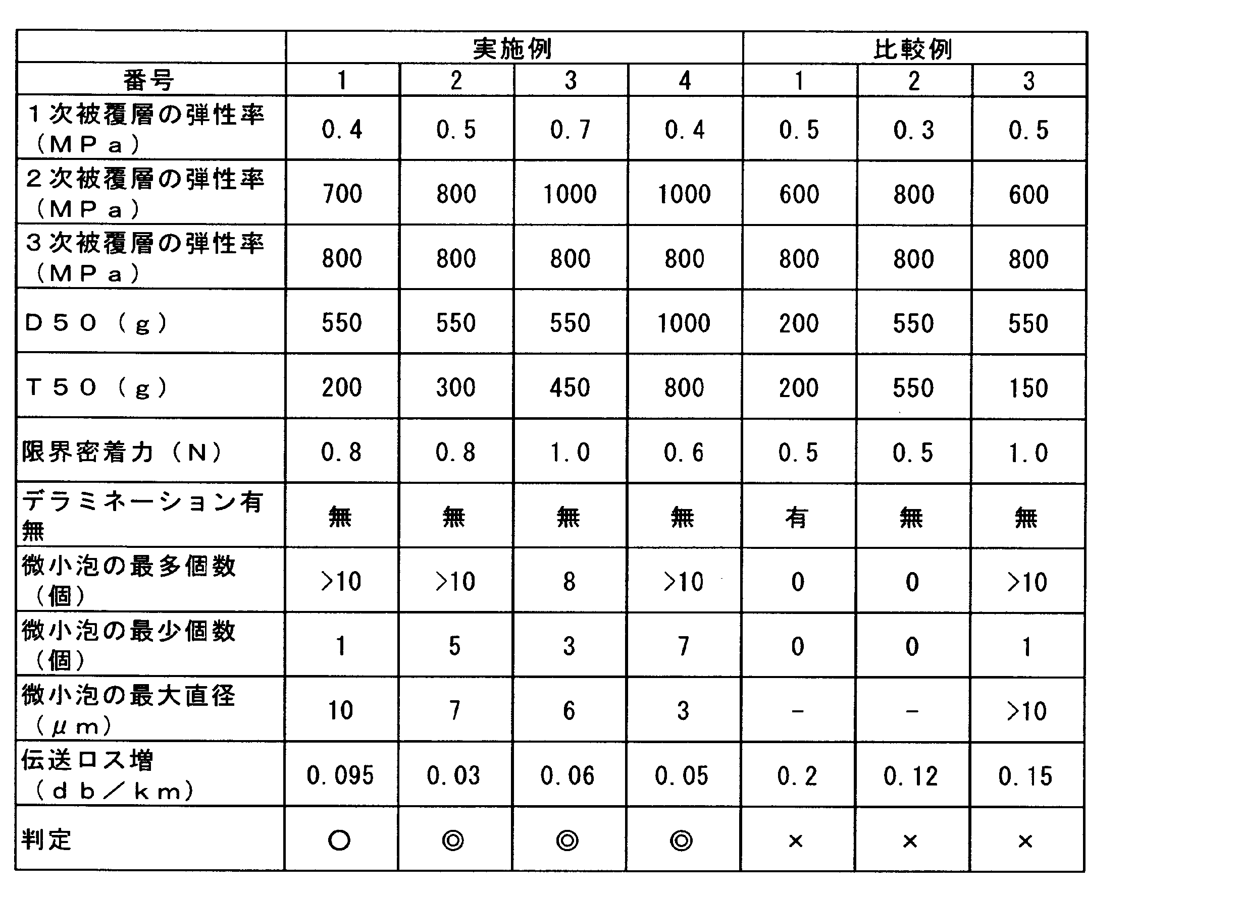
具体的には、温水浸漬後に約10cm分の光ファイバ心線を切り出し、該光ファイバ心線の一端から約3cmごとに3つの地点(3cm、6cm、9cm)で観察を行い、さらに該光ファイバ心線を断面の円周方向に90度回転させ、該3つの地点で再度観察を行った。以上の計6つの観察箇所において、光ファイバ心線の長手方向の垂直方向から、それぞれ1次被覆層内の厚さ方向30μm、長手方向30μmの範囲(1次被覆層の厚さが30μmなので、1次被覆層の厚さを1単位とした単位面積という)でデラミネーション発生の有無、水泡の個数および大きさを測定した。このように測定することにより、光ファイバ心線の長手方向だけでなく、断面の円周方向についても、水泡が一様に発生しているか否かを判定することができる。
微小泡の最多個数は、該6つの観察箇所の中で、観察された最も多い水泡の個数を表す。また、微小泡の最少個数は、該6つの観察箇所の中で、観察された最も少ない水泡の個数を表す。水泡の個数が10個より多い場合には、「>10」と表記している。
微小泡の最大直径は、該6つの観察箇所の中で、最も大きい水泡の直径を表す。なお、水泡の形状が楕円状の場合、水泡の中心を通る最も長い距離を水泡の直径とした。水泡の直径が10μmより大きい場合には、「>10」と表記している。
一般的に、伝送ロス増が0.1dB/km未満であれば、実用上問題ないとされている。そのため、0.1dB/km以上の場合は耐水性が不十分である(判定が×)とし、0.1dB/km未満の場合は耐水性が十分である(判定が○)とし、さらに0.07dB/km未満の場合は耐水性が優れている(判定が◎)として評価した。
また、水泡が1個以上発生している場合であっても、水泡の最大直径が10μmより大きい場合(比較例3)よりも、水泡の最大直径が10μm以下の場合(実施例1~4)の方が、伝送ロス増が低減されていることがわかる。
観測した全ての地点において最低1個以上の水泡が発生しているということは、1次被覆層中にほぼ一様に水泡が形成されているといえる。したがって、60℃、200日間の温水浸漬時に1次被覆層中に小さい水泡がほぼ一様に発生することによって、2次被覆層からガラスプライマリ界面への応力が緩和され、伝送ロス増が低減されていると考えられる。具体的には、水泡が1次被覆層中にほぼ一様に形成され、水泡の大きさが直径10μm以下であり、水泡が1次被覆層の長手方向断面の単位面積あたり1個以上存在しているときに、伝送ロス増が低減されている。該単位面積は、1次被覆層の厚さを1単位とし、該1次被覆層の厚さの自乗の範囲として定義する。
Claims (7)
- ガラスファイバと、該ガラスファイバの外周に被覆される1次被覆層と、該1次被覆層の外周に被覆される2次被覆層を有する光ファイバ素線と、該光ファイバ素線の外周に被覆される弾性率が100MPa以上の3次被覆層とを備える光ファイバ心線であって、
前記光ファイバ心線は、60℃の温水に200日間浸漬された場合に、前記1次被覆層の内部にほぼ一様に水泡が生じ、
前記水泡は、前記光ファイバ心線の長手方向に沿って切断した断面において、前記1次被覆層中に前記1次被覆層の厚さを1単位とした単位面積あたり1個以上存在し、
前記水泡の直径は10μm以下である
ことを特徴とする光ファイバ心線。 - 前記光ファイバ心線の長手方向の垂直方向から荷重を掛けた場合に50%の割合でデラミネーションが起こるときの第1の荷重が、前記光ファイバ心線の長手方向の垂直方向から荷重を掛けた場合に50%の割合でテアーが起こるときの第2の荷重より大きいことを特徴とする請求項1に記載の光ファイバ心線。
- 前記第1の荷重が500g以上であり、前記第2の荷重が200g以上であること特徴とする請求項2に記載の光ファイバ心線。
- 前記3次被覆層が着色層であることを特徴とする請求項1乃至3のいずれかに記載の光ファイバ心線。
- 請求項4に記載の光ファイバ心線を複数本平行に並べて一括被覆してなることを特徴とする光ファイバテープ心線。
- ガラスファイバと、該ガラスファイバの外周に被覆される1次被覆層と、該1次被覆層の外周に被覆される2次被覆層を有する光ファイバ素線を複数本平行に並べ、弾性率が100MPa以上の3次被覆層である一括被覆層によって一括被覆してなる光ファイバテープ心線であって、
前記光ファイバテープ心線は、60℃の温水に200日間浸漬された場合に、前記1次被覆層の内部にほぼ一様に水泡が生じ、
前記水泡は、前記光ファイバテープ心線の長手方向に沿って切断した断面において、前記1次被覆層中に前記1次被覆層の厚さを1単位とした単位面積あたり1個以上存在し、
前記水泡の直径は10μm以下である
ことを特徴とする光ファイバテープ心線。 - 請求項5または6に記載の光ファイバテープ心線を複数枚重ねて収容体に収容してなることを特徴とする光ファイバケーブル。
Priority Applications (5)
| Application Number | Priority Date | Filing Date | Title |
|---|---|---|---|
| IN4882CHN2014 IN2014CN04882A (ja) | 2012-02-17 | 2012-12-17 | |
| EP12868568.2A EP2816384A4 (en) | 2012-02-17 | 2012-12-17 | OPTIC FIBER C UR YARN, OPTICALLY FIBER C UR CABLE YARN AND OPTICAL CABLE |
| BR112014019240A BR112014019240A8 (pt) | 2012-02-17 | 2012-12-17 | Fibra óptica revestida, fita de fibras ópticas, e, cabo óptico |
| CN201280069889.8A CN104115049B (zh) | 2012-02-17 | 2012-12-17 | 涂覆光学纤维、光学纤维带及光缆 |
| US14/296,003 US9846292B2 (en) | 2012-02-17 | 2014-06-04 | Coated optical fiber, optical fiber ribbon, and optical cable |
Applications Claiming Priority (2)
| Application Number | Priority Date | Filing Date | Title |
|---|---|---|---|
| JP2012033088A JP5465741B2 (ja) | 2012-02-17 | 2012-02-17 | 光ファイバ心線、光ファイバテープ心線および光ケーブル |
| JP2012-033088 | 2012-02-17 |
Related Child Applications (1)
| Application Number | Title | Priority Date | Filing Date |
|---|---|---|---|
| US14/296,003 Continuation US9846292B2 (en) | 2012-02-17 | 2014-06-04 | Coated optical fiber, optical fiber ribbon, and optical cable |
Publications (1)
| Publication Number | Publication Date |
|---|---|
| WO2013121494A1 true WO2013121494A1 (ja) | 2013-08-22 |
Family
ID=48983663
Family Applications (1)
| Application Number | Title | Priority Date | Filing Date |
|---|---|---|---|
| PCT/JP2012/008037 Ceased WO2013121494A1 (ja) | 2012-02-17 | 2012-12-17 | 光ファイバ心線、光ファイバテープ心線および光ケーブル |
Country Status (7)
| Country | Link |
|---|---|
| US (1) | US9846292B2 (ja) |
| EP (1) | EP2816384A4 (ja) |
| JP (1) | JP5465741B2 (ja) |
| CN (1) | CN104115049B (ja) |
| BR (1) | BR112014019240A8 (ja) |
| IN (1) | IN2014CN04882A (ja) |
| WO (1) | WO2013121494A1 (ja) |
Families Citing this family (8)
| Publication number | Priority date | Publication date | Assignee | Title |
|---|---|---|---|---|
| JP6569429B2 (ja) * | 2015-09-25 | 2019-09-04 | 住友電気工業株式会社 | 光ファイバテープ心線 |
| KR102325812B1 (ko) * | 2016-09-30 | 2021-11-11 | 가부시키가이샤후지쿠라 | 광섬유 착색 심선, 광섬유 케이블 및 광섬유 착색 심선의 제조 방법 |
| WO2018062365A1 (ja) | 2016-09-30 | 2018-04-05 | 株式会社フジクラ | 光ファイバリボン、光ファイバケーブル、および光ファイバリボンの製造方法 |
| US10451795B2 (en) * | 2017-11-16 | 2019-10-22 | Ofs Fitel, Llc | Optical fiber for applications requiring high system optical signal-to-noise ratio performance and low degradation from nonlinear impairments |
| US11249272B2 (en) * | 2018-01-10 | 2022-02-15 | Sumitomo Electric Industries, Ltd. | Optical fiber cable and manufacturing method of optical fiber cable |
| WO2021161460A1 (ja) * | 2020-02-13 | 2021-08-19 | 日本電信電話株式会社 | 光ファイバのマイクロベンドを検知する装置及び方法 |
| WO2022085595A1 (ja) * | 2020-10-19 | 2022-04-28 | 住友電気工業株式会社 | 光ファイバテープ心線 |
| US20230236356A1 (en) * | 2022-01-25 | 2023-07-27 | Corning Research & Development Corporation | Single-mode optical fiber with dyed thin coating |
Citations (5)
| Publication number | Priority date | Publication date | Assignee | Title |
|---|---|---|---|---|
| JPH06109955A (ja) * | 1992-09-25 | 1994-04-22 | Mitsubishi Cable Ind Ltd | 超多心ケーブル用高密度テープ心線 |
| JP2004054138A (ja) | 2002-07-23 | 2004-02-19 | Furukawa Electric Co Ltd:The | 光ファイバ心線 |
| JP2008040369A (ja) | 2006-08-10 | 2008-02-21 | Furukawa Electric Co Ltd:The | 光ファイバ |
| JP2008197258A (ja) * | 2007-02-09 | 2008-08-28 | Sumitomo Electric Ind Ltd | 光ケーブル |
| JP2010217800A (ja) | 2009-03-19 | 2010-09-30 | Furukawa Electric Co Ltd:The | 光ファイバ |
Family Cites Families (23)
| Publication number | Priority date | Publication date | Assignee | Title |
|---|---|---|---|---|
| JP3741446B2 (ja) * | 1992-10-14 | 2006-02-01 | 大日本インキ化学工業株式会社 | 光ファイバ一次被覆用紫外線硬化型樹脂組成物 |
| JP2003277453A (ja) * | 2002-03-27 | 2003-10-02 | Jsr Corp | 液状硬化性樹脂組成物 |
| JP2004212722A (ja) * | 2003-01-06 | 2004-07-29 | Fuji Photo Film Co Ltd | 光学部材、その製造に用いられる重合性組成物及び製造方法、並びにそれを用いた光通信システム |
| US7400808B2 (en) * | 2003-01-10 | 2008-07-15 | The Furukawa Electric Co., Ltd. | Optical fiber, light amplifier, and light source |
| JP2005316235A (ja) * | 2004-04-30 | 2005-11-10 | Fujikura Ltd | 光ファイバ心線、光ファイバテープ心線、光ファイバケーブル、及び光ファイバドロップケーブル |
| CN2869902Y (zh) * | 2006-03-09 | 2007-02-14 | 深圳市特发信息股份有限公司光缆分公司 | 骨架式光纤带光缆 |
| JP2007272060A (ja) | 2006-03-31 | 2007-10-18 | Furukawa Electric Co Ltd:The | 光ファイバリボン芯線及び光ファイバケーブル |
| JP2007333795A (ja) * | 2006-06-12 | 2007-12-27 | Furukawa Electric Co Ltd:The | 光ファイバ心線及びその製造方法 |
| WO2008012926A1 (fr) | 2006-07-28 | 2008-01-31 | The Furukawa Electric Co., Ltd. | Fibre optique |
| CN101228468B (zh) * | 2006-08-10 | 2011-06-08 | 古河电气工业株式会社 | 光纤 |
| US7978948B2 (en) | 2006-09-08 | 2011-07-12 | The Furukawa Electric Co., Ltd. | Optical fiber and optical fiber ribbon |
| US8184937B2 (en) | 2007-02-08 | 2012-05-22 | Sumitomo Electric Industries, Ltd. | Optical cable |
| JP2008224744A (ja) * | 2007-03-08 | 2008-09-25 | Furukawa Electric Co Ltd:The | 光ファイバ心線 |
| CN101512404B (zh) | 2007-08-22 | 2012-10-10 | 古河电气工业株式会社 | 光纤带状芯线 |
| JP2009181119A (ja) * | 2008-01-29 | 2009-08-13 | Sumitomo Electric Ind Ltd | 光ケーブル |
| JP2009222855A (ja) * | 2008-03-14 | 2009-10-01 | Furukawa Electric Co Ltd:The | 光ファイバ心線 |
| JP5323664B2 (ja) * | 2009-12-17 | 2013-10-23 | 古河電気工業株式会社 | 光ファイバ心線 |
| JP5823128B2 (ja) | 2010-01-19 | 2015-11-25 | 古河電気工業株式会社 | 光ファイバの製造方法 |
| JP2012018258A (ja) | 2010-07-07 | 2012-01-26 | Furukawa Electric Co Ltd:The | 光ファイバ心線 |
| JP4865891B1 (ja) | 2010-07-22 | 2012-02-01 | 古河電気工業株式会社 | 光ファイバ素線、光ファイバテープ心線および光ファイバケーブル |
| JP5041450B2 (ja) | 2010-11-24 | 2012-10-03 | 古河電気工業株式会社 | 光ファイバ着色心線 |
| JP5027318B2 (ja) | 2011-02-04 | 2012-09-19 | 古河電気工業株式会社 | 光ファイバ心線 |
| JP5294357B2 (ja) | 2012-02-15 | 2013-09-18 | 古河電気工業株式会社 | 光ファイバ着色心線、光ファイバテープ心線及び光ファイバケーブル |
-
2012
- 2012-02-17 JP JP2012033088A patent/JP5465741B2/ja not_active Expired - Fee Related
- 2012-12-17 BR BR112014019240A patent/BR112014019240A8/pt not_active Application Discontinuation
- 2012-12-17 EP EP12868568.2A patent/EP2816384A4/en not_active Withdrawn
- 2012-12-17 WO PCT/JP2012/008037 patent/WO2013121494A1/ja not_active Ceased
- 2012-12-17 IN IN4882CHN2014 patent/IN2014CN04882A/en unknown
- 2012-12-17 CN CN201280069889.8A patent/CN104115049B/zh not_active Expired - Fee Related
-
2014
- 2014-06-04 US US14/296,003 patent/US9846292B2/en not_active Expired - Fee Related
Patent Citations (5)
| Publication number | Priority date | Publication date | Assignee | Title |
|---|---|---|---|---|
| JPH06109955A (ja) * | 1992-09-25 | 1994-04-22 | Mitsubishi Cable Ind Ltd | 超多心ケーブル用高密度テープ心線 |
| JP2004054138A (ja) | 2002-07-23 | 2004-02-19 | Furukawa Electric Co Ltd:The | 光ファイバ心線 |
| JP2008040369A (ja) | 2006-08-10 | 2008-02-21 | Furukawa Electric Co Ltd:The | 光ファイバ |
| JP2008197258A (ja) * | 2007-02-09 | 2008-08-28 | Sumitomo Electric Ind Ltd | 光ケーブル |
| JP2010217800A (ja) | 2009-03-19 | 2010-09-30 | Furukawa Electric Co Ltd:The | 光ファイバ |
Non-Patent Citations (2)
| Title |
|---|
| CHARLES ALOISIO ET AL.: "Optical Fiber Coating Delamination Using Model Coating Materials", PROCEEDINGS OF THE 51ST IWCS, 2002, pages 738 - 747 |
| See also references of EP2816384A4 |
Also Published As
| Publication number | Publication date |
|---|---|
| US9846292B2 (en) | 2017-12-19 |
| JP2013171072A (ja) | 2013-09-02 |
| CN104115049A (zh) | 2014-10-22 |
| BR112014019240A8 (pt) | 2017-07-11 |
| US20150293325A1 (en) | 2015-10-15 |
| EP2816384A1 (en) | 2014-12-24 |
| CN104115049B (zh) | 2018-01-02 |
| IN2014CN04882A (ja) | 2015-09-18 |
| EP2816384A4 (en) | 2015-11-11 |
| JP5465741B2 (ja) | 2014-04-09 |
| BR112014019240A2 (ja) | 2017-06-20 |
Similar Documents
| Publication | Publication Date | Title |
|---|---|---|
| JP5465741B2 (ja) | 光ファイバ心線、光ファイバテープ心線および光ケーブル | |
| JP4865891B1 (ja) | 光ファイバ素線、光ファイバテープ心線および光ファイバケーブル | |
| JP5323664B2 (ja) | 光ファイバ心線 | |
| US11256051B2 (en) | Flexible optical-fiber ribbon | |
| JP5255690B2 (ja) | 光ファイバ着色心線、光ファイバテープ心線および光ファイバケーブル | |
| JP2013167762A (ja) | 光ファイバ着色心線、光ファイバテープ心線及び光ファイバケーブル | |
| JP6067332B2 (ja) | 光ファイバテープ心線 | |
| WO2012105246A1 (ja) | 光ファイバ心線 | |
| JP2007272060A (ja) | 光ファイバリボン芯線及び光ファイバケーブル | |
| CN101512404B (zh) | 光纤带状芯线 | |
| JP2010217800A (ja) | 光ファイバ | |
| JP4850732B2 (ja) | 光ファイバテープおよび光ケーブル | |
| JP2010210711A (ja) | 光ファイバ心線 | |
| JP4845007B2 (ja) | 光ファイバ心線および光ファイバテープ心線とその製造方法 | |
| JP4630210B2 (ja) | 光ファイバテープ心線およびその心線の密着力測定法 | |
| JP4249202B2 (ja) | 光ファイバテープおよび光ケーブル | |
| JP2009133958A (ja) | オーバーコート心線及びケーブル | |
| JP2003241039A (ja) | 光ファイバテープ心線およびその製造方法 | |
| JP2006208940A (ja) | 光ファイバテープおよび光ケーブル | |
| JP4144613B2 (ja) | 光ファイバ心線、それを用いた光ファイバテープユニットおよび光ファイバケーブル | |
| JP4947617B2 (ja) | 光ファイバ心線および光ファイバテープ心線 | |
| JP2006078913A (ja) | 光ファイバテープおよび光ファイバケーブル | |
| JP2004045937A (ja) | 光ファイバテープ心線 | |
| JP2002372655A (ja) | 光ファイバテープ心線 | |
| JP2007264193A (ja) | 光ファイバケーブル |
Legal Events
| Date | Code | Title | Description |
|---|---|---|---|
| 121 | Ep: the epo has been informed by wipo that ep was designated in this application |
Ref document number: 12868568 Country of ref document: EP Kind code of ref document: A1 |
|
| REEP | Request for entry into the european phase |
Ref document number: 2012868568 Country of ref document: EP |
|
| WWE | Wipo information: entry into national phase |
Ref document number: 2012868568 Country of ref document: EP |
|
| NENP | Non-entry into the national phase |
Ref country code: DE |
|
| REG | Reference to national code |
Ref country code: BR Ref legal event code: B01A Ref document number: 112014019240 Country of ref document: BR |
|
| ENP | Entry into the national phase |
Ref document number: 112014019240 Country of ref document: BR Kind code of ref document: A2 Effective date: 20140804 |