WO2013122030A1 - 走行制御装置及び走行制御方法 - Google Patents
走行制御装置及び走行制御方法 Download PDFInfo
- Publication number
- WO2013122030A1 WO2013122030A1 PCT/JP2013/053199 JP2013053199W WO2013122030A1 WO 2013122030 A1 WO2013122030 A1 WO 2013122030A1 JP 2013053199 W JP2013053199 W JP 2013053199W WO 2013122030 A1 WO2013122030 A1 WO 2013122030A1
- Authority
- WO
- WIPO (PCT)
- Prior art keywords
- obstacle
- unit
- distance
- warning
- detection unit
- Prior art date
- Legal status (The legal status is an assumption and is not a legal conclusion. Google has not performed a legal analysis and makes no representation as to the accuracy of the status listed.)
- Ceased
Links
Images


Classifications
-
- G—PHYSICS
- G08—SIGNALLING
- G08G—TRAFFIC CONTROL SYSTEMS
- G08G9/00—Traffic control systems for craft where the kind of craft is irrelevant or unspecified
- G08G9/02—Anti-collision systems
-
- B—PERFORMING OPERATIONS; TRANSPORTING
- B60—VEHICLES IN GENERAL
- B60Q—ARRANGEMENT OF SIGNALLING OR LIGHTING DEVICES, THE MOUNTING OR SUPPORTING THEREOF OR CIRCUITS THEREFOR, FOR VEHICLES IN GENERAL
- B60Q9/00—Arrangement or adaptation of signal devices not provided for in one of main groups B60Q1/00 - B60Q7/00, e.g. haptic signalling
- B60Q9/008—Arrangement or adaptation of signal devices not provided for in one of main groups B60Q1/00 - B60Q7/00, e.g. haptic signalling for anti-collision purposes
-
- G—PHYSICS
- G01—MEASURING; TESTING
- G01S—RADIO DIRECTION-FINDING; RADIO NAVIGATION; DETERMINING DISTANCE OR VELOCITY BY USE OF RADIO WAVES; LOCATING OR PRESENCE-DETECTING BY USE OF THE REFLECTION OR RERADIATION OF RADIO WAVES; ANALOGOUS ARRANGEMENTS USING OTHER WAVES
- G01S13/00—Systems using the reflection or reradiation of radio waves, e.g. radar systems; Analogous systems using reflection or reradiation of waves whose nature or wavelength is irrelevant or unspecified
- G01S13/86—Combinations of radar systems with non-radar systems, e.g. sonar, direction finder
- G01S13/862—Combination of radar systems with sonar systems
-
- G—PHYSICS
- G01—MEASURING; TESTING
- G01S—RADIO DIRECTION-FINDING; RADIO NAVIGATION; DETERMINING DISTANCE OR VELOCITY BY USE OF RADIO WAVES; LOCATING OR PRESENCE-DETECTING BY USE OF THE REFLECTION OR RERADIATION OF RADIO WAVES; ANALOGOUS ARRANGEMENTS USING OTHER WAVES
- G01S13/00—Systems using the reflection or reradiation of radio waves, e.g. radar systems; Analogous systems using reflection or reradiation of waves whose nature or wavelength is irrelevant or unspecified
- G01S13/88—Radar or analogous systems specially adapted for specific applications
- G01S13/93—Radar or analogous systems specially adapted for specific applications for anti-collision purposes
- G01S13/931—Radar or analogous systems specially adapted for specific applications for anti-collision purposes of land vehicles
-
- G—PHYSICS
- G01—MEASURING; TESTING
- G01S—RADIO DIRECTION-FINDING; RADIO NAVIGATION; DETERMINING DISTANCE OR VELOCITY BY USE OF RADIO WAVES; LOCATING OR PRESENCE-DETECTING BY USE OF THE REFLECTION OR RERADIATION OF RADIO WAVES; ANALOGOUS ARRANGEMENTS USING OTHER WAVES
- G01S15/00—Systems using the reflection or reradiation of acoustic waves, e.g. sonar systems
- G01S15/87—Combinations of sonar systems
- G01S15/876—Combination of several spaced transmitters or receivers of known location for determining the position of a transponder or a reflector
-
- G—PHYSICS
- G01—MEASURING; TESTING
- G01S—RADIO DIRECTION-FINDING; RADIO NAVIGATION; DETERMINING DISTANCE OR VELOCITY BY USE OF RADIO WAVES; LOCATING OR PRESENCE-DETECTING BY USE OF THE REFLECTION OR RERADIATION OF RADIO WAVES; ANALOGOUS ARRANGEMENTS USING OTHER WAVES
- G01S15/00—Systems using the reflection or reradiation of acoustic waves, e.g. sonar systems
- G01S15/88—Sonar systems specially adapted for specific applications
- G01S15/93—Sonar systems specially adapted for specific applications for anti-collision purposes
- G01S15/931—Sonar systems specially adapted for specific applications for anti-collision purposes of land vehicles
-
- G—PHYSICS
- G08—SIGNALLING
- G08G—TRAFFIC CONTROL SYSTEMS
- G08G1/00—Traffic control systems for road vehicles
- G08G1/16—Anti-collision systems
- G08G1/166—Anti-collision systems for active traffic, e.g. moving vehicles, pedestrians, bikes
-
- G—PHYSICS
- G01—MEASURING; TESTING
- G01S—RADIO DIRECTION-FINDING; RADIO NAVIGATION; DETERMINING DISTANCE OR VELOCITY BY USE OF RADIO WAVES; LOCATING OR PRESENCE-DETECTING BY USE OF THE REFLECTION OR RERADIATION OF RADIO WAVES; ANALOGOUS ARRANGEMENTS USING OTHER WAVES
- G01S13/00—Systems using the reflection or reradiation of radio waves, e.g. radar systems; Analogous systems using reflection or reradiation of waves whose nature or wavelength is irrelevant or unspecified
- G01S13/87—Combinations of radar systems, e.g. primary radar and secondary radar
-
- G—PHYSICS
- G01—MEASURING; TESTING
- G01S—RADIO DIRECTION-FINDING; RADIO NAVIGATION; DETERMINING DISTANCE OR VELOCITY BY USE OF RADIO WAVES; LOCATING OR PRESENCE-DETECTING BY USE OF THE REFLECTION OR RERADIATION OF RADIO WAVES; ANALOGOUS ARRANGEMENTS USING OTHER WAVES
- G01S13/00—Systems using the reflection or reradiation of radio waves, e.g. radar systems; Analogous systems using reflection or reradiation of waves whose nature or wavelength is irrelevant or unspecified
- G01S13/88—Radar or analogous systems specially adapted for specific applications
- G01S13/93—Radar or analogous systems specially adapted for specific applications for anti-collision purposes
- G01S13/931—Radar or analogous systems specially adapted for specific applications for anti-collision purposes of land vehicles
- G01S2013/9315—Monitoring blind spots
-
- G—PHYSICS
- G01—MEASURING; TESTING
- G01S—RADIO DIRECTION-FINDING; RADIO NAVIGATION; DETERMINING DISTANCE OR VELOCITY BY USE OF RADIO WAVES; LOCATING OR PRESENCE-DETECTING BY USE OF THE REFLECTION OR RERADIATION OF RADIO WAVES; ANALOGOUS ARRANGEMENTS USING OTHER WAVES
- G01S13/00—Systems using the reflection or reradiation of radio waves, e.g. radar systems; Analogous systems using reflection or reradiation of waves whose nature or wavelength is irrelevant or unspecified
- G01S13/88—Radar or analogous systems specially adapted for specific applications
- G01S13/93—Radar or analogous systems specially adapted for specific applications for anti-collision purposes
- G01S13/931—Radar or analogous systems specially adapted for specific applications for anti-collision purposes of land vehicles
- G01S2013/9317—Driving backwards
-
- G—PHYSICS
- G01—MEASURING; TESTING
- G01S—RADIO DIRECTION-FINDING; RADIO NAVIGATION; DETERMINING DISTANCE OR VELOCITY BY USE OF RADIO WAVES; LOCATING OR PRESENCE-DETECTING BY USE OF THE REFLECTION OR RERADIATION OF RADIO WAVES; ANALOGOUS ARRANGEMENTS USING OTHER WAVES
- G01S13/00—Systems using the reflection or reradiation of radio waves, e.g. radar systems; Analogous systems using reflection or reradiation of waves whose nature or wavelength is irrelevant or unspecified
- G01S13/88—Radar or analogous systems specially adapted for specific applications
- G01S13/93—Radar or analogous systems specially adapted for specific applications for anti-collision purposes
- G01S13/931—Radar or analogous systems specially adapted for specific applications for anti-collision purposes of land vehicles
- G01S2013/932—Radar or analogous systems specially adapted for specific applications for anti-collision purposes of land vehicles using own vehicle data, e.g. ground speed, steering wheel direction
-
- G—PHYSICS
- G01—MEASURING; TESTING
- G01S—RADIO DIRECTION-FINDING; RADIO NAVIGATION; DETERMINING DISTANCE OR VELOCITY BY USE OF RADIO WAVES; LOCATING OR PRESENCE-DETECTING BY USE OF THE REFLECTION OR RERADIATION OF RADIO WAVES; ANALOGOUS ARRANGEMENTS USING OTHER WAVES
- G01S13/00—Systems using the reflection or reradiation of radio waves, e.g. radar systems; Analogous systems using reflection or reradiation of waves whose nature or wavelength is irrelevant or unspecified
- G01S13/88—Radar or analogous systems specially adapted for specific applications
- G01S13/93—Radar or analogous systems specially adapted for specific applications for anti-collision purposes
- G01S13/931—Radar or analogous systems specially adapted for specific applications for anti-collision purposes of land vehicles
- G01S2013/9322—Radar or analogous systems specially adapted for specific applications for anti-collision purposes of land vehicles using additional data, e.g. driver condition, road state or weather data
-
- G—PHYSICS
- G01—MEASURING; TESTING
- G01S—RADIO DIRECTION-FINDING; RADIO NAVIGATION; DETERMINING DISTANCE OR VELOCITY BY USE OF RADIO WAVES; LOCATING OR PRESENCE-DETECTING BY USE OF THE REFLECTION OR RERADIATION OF RADIO WAVES; ANALOGOUS ARRANGEMENTS USING OTHER WAVES
- G01S13/00—Systems using the reflection or reradiation of radio waves, e.g. radar systems; Analogous systems using reflection or reradiation of waves whose nature or wavelength is irrelevant or unspecified
- G01S13/88—Radar or analogous systems specially adapted for specific applications
- G01S13/93—Radar or analogous systems specially adapted for specific applications for anti-collision purposes
- G01S13/931—Radar or analogous systems specially adapted for specific applications for anti-collision purposes of land vehicles
- G01S2013/9327—Sensor installation details
- G01S2013/93271—Sensor installation details in the front of the vehicles
-
- G—PHYSICS
- G01—MEASURING; TESTING
- G01S—RADIO DIRECTION-FINDING; RADIO NAVIGATION; DETERMINING DISTANCE OR VELOCITY BY USE OF RADIO WAVES; LOCATING OR PRESENCE-DETECTING BY USE OF THE REFLECTION OR RERADIATION OF RADIO WAVES; ANALOGOUS ARRANGEMENTS USING OTHER WAVES
- G01S13/00—Systems using the reflection or reradiation of radio waves, e.g. radar systems; Analogous systems using reflection or reradiation of waves whose nature or wavelength is irrelevant or unspecified
- G01S13/88—Radar or analogous systems specially adapted for specific applications
- G01S13/93—Radar or analogous systems specially adapted for specific applications for anti-collision purposes
- G01S13/931—Radar or analogous systems specially adapted for specific applications for anti-collision purposes of land vehicles
- G01S2013/9327—Sensor installation details
- G01S2013/93272—Sensor installation details in the back of the vehicles
-
- G—PHYSICS
- G01—MEASURING; TESTING
- G01S—RADIO DIRECTION-FINDING; RADIO NAVIGATION; DETERMINING DISTANCE OR VELOCITY BY USE OF RADIO WAVES; LOCATING OR PRESENCE-DETECTING BY USE OF THE REFLECTION OR RERADIATION OF RADIO WAVES; ANALOGOUS ARRANGEMENTS USING OTHER WAVES
- G01S13/00—Systems using the reflection or reradiation of radio waves, e.g. radar systems; Analogous systems using reflection or reradiation of waves whose nature or wavelength is irrelevant or unspecified
- G01S13/88—Radar or analogous systems specially adapted for specific applications
- G01S13/93—Radar or analogous systems specially adapted for specific applications for anti-collision purposes
- G01S13/931—Radar or analogous systems specially adapted for specific applications for anti-collision purposes of land vehicles
- G01S2013/9327—Sensor installation details
- G01S2013/93274—Sensor installation details on the side of the vehicles
-
- G—PHYSICS
- G01—MEASURING; TESTING
- G01S—RADIO DIRECTION-FINDING; RADIO NAVIGATION; DETERMINING DISTANCE OR VELOCITY BY USE OF RADIO WAVES; LOCATING OR PRESENCE-DETECTING BY USE OF THE REFLECTION OR RERADIATION OF RADIO WAVES; ANALOGOUS ARRANGEMENTS USING OTHER WAVES
- G01S15/00—Systems using the reflection or reradiation of acoustic waves, e.g. sonar systems
- G01S15/88—Sonar systems specially adapted for specific applications
- G01S15/93—Sonar systems specially adapted for specific applications for anti-collision purposes
- G01S15/931—Sonar systems specially adapted for specific applications for anti-collision purposes of land vehicles
- G01S2015/932—Sonar systems specially adapted for specific applications for anti-collision purposes of land vehicles for parking operations
-
- G—PHYSICS
- G01—MEASURING; TESTING
- G01S—RADIO DIRECTION-FINDING; RADIO NAVIGATION; DETERMINING DISTANCE OR VELOCITY BY USE OF RADIO WAVES; LOCATING OR PRESENCE-DETECTING BY USE OF THE REFLECTION OR RERADIATION OF RADIO WAVES; ANALOGOUS ARRANGEMENTS USING OTHER WAVES
- G01S15/00—Systems using the reflection or reradiation of acoustic waves, e.g. sonar systems
- G01S15/88—Sonar systems specially adapted for specific applications
- G01S15/93—Sonar systems specially adapted for specific applications for anti-collision purposes
- G01S15/931—Sonar systems specially adapted for specific applications for anti-collision purposes of land vehicles
- G01S2015/937—Sonar systems specially adapted for specific applications for anti-collision purposes of land vehicles sensor installation details
- G01S2015/938—Sonar systems specially adapted for specific applications for anti-collision purposes of land vehicles sensor installation details in the bumper area
Definitions
- the present invention relates to a travel control device and a travel control method.
- Patent Document 1 a technique for detecting an obstacle approaching the periphery of a vehicle using an obstacle sensor mounted on the vehicle is known (see, for example, Patent Document 1).
- an ultrasonic sensor having a detection area at the rear of the vehicle and an ultrasonic sensor having a detection area at the rear side of the vehicle are mounted at the rear of the vehicle.
- An ultrasonic sensor having a detection area on the rear side of the vehicle has a detection area that can detect an obstacle far to the rear, whereas an ultrasonic sensor having a detection area on the rear side of the vehicle is in the vicinity of the own vehicle. Obstacles can only be detected. Therefore, there is a non-detection area in which an obstacle cannot be detected far behind the vehicle.
- the ultrasonic sensor having the detection area on the rear side of the vehicle even if an obstacle is detected, a warning is not issued unless the distance to the obstacle and the approach time are below the warning threshold. If an obstacle moves from there to the undetected area behind the vehicle, no ultrasonic sensor can detect the obstacle until the ultrasonic sensor that detects the rear of the vehicle detects the obstacle. Object detection may be delayed.
- the present invention has been made in view of the above problems, and its purpose is to appropriately detect an obstacle even if an obstacle enters the non-detection area, and to suppress a delay in warning timing and a non-warning when the vehicle moves backward.
- a travel control device and a travel control method are provided.
- the travel control device includes a rear obstacle detection unit, a side obstacle detection unit, a rear movement preparation detection unit, a warning unit, and a control unit.
- the rear obstacle detection unit detects an obstacle entering behind the host vehicle and a distance from the obstacle.
- the side obstacle detection unit detects an obstacle entering the predetermined side detection area including the rear side of the host vehicle and a distance from the obstacle.
- the backward movement preparation detection unit detects preparation that the host vehicle moves backward.
- the warning unit warns the obstacle detected by the rear obstacle detection unit or the side obstacle detection unit.
- the control unit has a parameter based on the distance from the obstacle detected by the side obstacle detecting unit when the distance from the obstacle detected by the rear obstacle detecting unit is equal to or less than the first warning threshold value.
- the warning unit is controlled to issue a warning when the second warning threshold value is reached.
- the control unit increases the first warning threshold until the holding time elapses after the side obstacle detection unit cannot detect the obstacle.
- the travel control method uses a travel control device having the rear obstacle detection unit, the side obstacle detection unit, the rearward movement preparation detection unit, and the warning unit.
- a traveling control method based on a distance from an obstacle detected by a rear obstacle detection unit when the distance from the obstacle detected by the rear obstacle detection unit is equal to or less than a first warning threshold value or from an obstacle detected by a side obstacle detection unit
- the warning unit is controlled so as to give a warning
- the backward movement preparation detection unit detects the preparation for the vehicle to move backward, and the side obstacle is detected.
- the time until the holding time elapses after the side obstacle detection unit cannot detect the obstacle Increase the first warning threshold.
- FIG. 1 is a schematic diagram illustrating a vehicle layout example of a travel control device according to an embodiment.
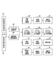
- FIG. 2 is a block diagram illustrating a configuration of the travel control apparatus according to the embodiment.
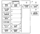
- FIG. 3 is a block diagram showing a specific configuration example of the host vehicle information acquisition unit 21 of FIG.
- FIG. 4 is a block diagram illustrating a specific configuration example of the peripheral information acquisition unit 22 of FIG.
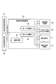
- FIG. 5 is a block diagram illustrating a specific configuration example of the control determination information calculation unit 24 of FIG.
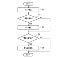
- FIG. 6 is a flowchart showing the operation of the travel control device when executing the travel control process.
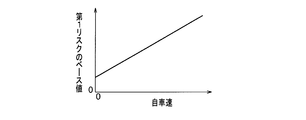
- FIG. 7 is a graph showing an example of the relationship between the host vehicle speed and the first risk (first warning threshold value).
- FIG. 8 is a graph showing an example of the relationship between the relative speed with the obstacle and the correction gain.
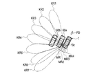
- FIG. 9 shows side detection areas KR1 to KR7 in which the side obstacle detection sensor 19c can detect obstacles, and rear detection areas MR1 to KR4 in which the rear obstacle detection sensors 13e to 13h can detect obstacles.
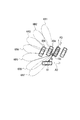
- FIG. FIG. 10 is a plan view showing a state of the vehicle 61 traveling in the direction AD oblique to the parking direction PD of the host vehicle 1 in the vicinity of the rear of the host vehicle 1.
- the vehicle 1 (hereinafter referred to as “own vehicle”) includes brake lamps 4 a and 4 b, an ignition switch 18 for instructing start and stop of a driving force generator including an engine and a motor, and an obstacle approaching the front PD of the own vehicle 1.
- Front obstacle detection sensors 13a to 13d and 19e for detecting an object, rear obstacle detection sensors 13e to 13h for detecting an obstacle approaching the rear of the vehicle 1, and an obstacle approaching the side of the vehicle 1 are detected.
- a driving force generator 36 for generating driving force of the own vehicle a driving force generator 36 for generating driving force of the own vehicle
- a braking force generator 27 an accelerator pedal operation reaction force generator 30, and the driver are notified of the approach of the obstacle.
- a vehicle control device 2 (control unit) that controls the entire host vehicle 1 are mounted.
- the vehicle control device 2 corresponds to a control unit of the travel control device according to the embodiment.
- the front obstacle detection sensors 13a to 13d are provided, for example, in the front bumper of the own vehicle 1, and the rear obstacle detection sensors 13e to 13h are provided, for example, in the rear bumper of the own vehicle 1.
- a sonar detection that detects the distance between the obstacle and the obstacle entering the relatively near area from the own vehicle 1 using ultrasonic waves.
- a machine can be used.
- One side obstacle detection sensor 19a to 19d is arranged on each of the left and right fenders near the front PD and the rear side of the host vehicle 1, and the front obstacle detection sensor 19e is, for example, in the front bumper of the host vehicle 1. Is provided.
- the vehicle control device 2 is configured by an arithmetic processing device such as an ECU (Engine Control Unit), and controls the operation of the entire host vehicle 1 by executing a computer program stored in advance by a CPU in the arithmetic processing device.
- ECU Engine Control Unit
- the travel control device includes a host vehicle information acquisition unit 21 that acquires information of the host vehicle 1, a peripheral information acquisition unit 22 that acquires information about the periphery of the host vehicle, a system state selection unit 23, and control determination information.
- a calculation unit 24 and a warning device that issues a warning to an obstacle detected by the surrounding information acquisition unit 22 are provided.
- the warning device includes a braking force generation system (25 to 27) that generates a braking force as an obstacle approach warning, and an accelerator pedal operation reaction force that generates an accelerator pedal operation reaction force as an obstacle approach warning.
- a system 28 to 30
- a notification system 31 to 33
- a driving force control system 34 to 36
- the host vehicle information acquisition unit 21 detects wheel speed sensors 11 a to 11 d installed on the wheels 20 a to 20 d of the host vehicle 1 and accelerator opening detection installed on the accelerator pedal of the host vehicle 1.
- a brake pedal position detector 6 that detects the position of the brake pedal of the vehicle 1
- a shift position detector 9 (rear movement preparation detector) that detects the shift position of the vehicle 1
- the SW operation recognition unit 3 that detects the state of the on / off switch, the steering sensor 10 that detects the steering angle of the steering of the host vehicle 1, and the acceleration / deceleration sensor 12 that detects the acceleration / deceleration of the host vehicle 1 are provided. .
- the wheel speed sensors 11a to 11d detect the rotational speeds of the wheels 20a to 20d of the vehicle 1 respectively.
- the own vehicle speed calculation unit 40 calculates the own vehicle speed (wheel speed) from the respective rotation speeds of the wheels 20a to 20d in consideration of the rotation radii of the wheels 20a to 20d. Further, the host vehicle speed calculation unit 40 calculates the travel distance by integrating the host vehicle speed.
- the brake pedal position detector 6 detects whether or not the driver is depressing the brake pedal and the amount of depression of the brake pedal.
- the shift position detector 9 detects the state of the shift position in order to detect the current state of the transmission. An example of detecting that the vehicle 1 is ready to move backward includes that the shift position detection unit 9 detects a reverse (R) position.
- the SW operation recognition unit 3 detects the switch state of the travel control device and the switch state of the ignition switch 18.
- the steering angle calculation unit 41 performs a filtering process on the steering angle of the steering detected by the steering sensor 10 as necessary.
- the acceleration / deceleration calculation unit 42 performs filter processing on the acceleration / deceleration of the host vehicle 1 detected by the acceleration / deceleration sensor 12 as necessary.
- the own vehicle information output unit 43 determines the vehicle speed of the own vehicle 1, the accelerator opening, the position of the brake pedal, the shift position, the state of the on / off switch of the travel control device, the steering angle and the acceleration / deceleration. The information is transferred to the system state selection unit 23 or the control determination information calculation unit 24.
- the own vehicle speed calculation unit 40, the steer angle calculation unit 41, the acceleration / deceleration calculation unit 42, and the own vehicle information output unit 43 can be configured as a part of the vehicle control device 2 of FIG.
- an arithmetic processing device different from the vehicle control device 2 is prepared, and a CPU in the arithmetic processing device executes a computer program stored in advance.
- the peripheral information acquisition unit 22 is a front obstacle detection sensor 13a to 13d, 19e installed at the front, rear and side portions of the vehicle 1 shown in FIG.
- Object detection sensors 13e to 13h and side obstacle detection sensors 19a to 19d are provided.
- the relative distance calculation unit 39 performs a filtering process on the value of the distance from the obstacle detected by the surrounding obstacle detection sensor 37 as necessary.
- the relative speed estimation unit 38 estimates the relative speed with the obstacle from the distance to the obstacle. The sign of the relative speed is positive when the obstacle approaches the host vehicle 1 and negative when the obstacle moves away.
- the relative speed estimation unit 38 calculates the time (approach time) required for the obstacle to approach the host vehicle 1 from the distance and relative speed with the obstacle detected by the side obstacle detection sensors 19a to 19d. calculate.
- the approach time may be, for example, TTC (collision time) obtained by dividing the distance from the obstacle by the relative speed.
- the obstacle presence / absence determination unit 44 outputs a signal indicating whether or not the surrounding obstacle detection sensor 37 has detected an obstacle.
- the surrounding information output unit 45 indicates the presence / absence of obstacles present in the front PD, rear and side of the vehicle 1, distance and relative speed with the obstacle, approach time, and obstacle detection direction or detection angle described later. The information is transferred to the system state selection unit 23 or the control determination information calculation unit 24 as peripheral information.
- the relative distance calculation unit 39, the relative speed estimation unit 38, the obstacle presence / absence determination unit 44, and the surrounding information output unit 45 can be configured as a part of the vehicle control device 2 in FIG.
- an arithmetic processing device different from the vehicle control device 2 is prepared, and a CPU in the arithmetic processing device executes a computer program stored in advance. Accordingly, the operations of the relative distance calculation unit 39, the relative speed estimation unit 38, the obstacle presence / absence determination unit 44, and the peripheral information output unit 45 may be realized.
- the system state selection unit 23 determines whether to turn the system state on or off based on the state of the on / off switch of the travel control device detected by the SW operation recognition unit 3.
- the side obstacle detection sensor 19c installed on the rear fender on the left rear side of the host vehicle 1 includes the side of the host vehicle 1 and is rearward from the side of the host vehicle 1 with the side obstacle detection sensor 19c as a center. It is possible to detect the vehicles 60a and 60b entering the fan-shaped region (side detection region) having a predetermined angle that spreads toward the front.
- the side obstacle detection sensor 19c divides the side detection region into a plurality of detection angle regions KR1 to KR7, and determines the distance between the obstacle and the obstacle entering the plurality of detection angle regions KR1 to KR7 as the detection angle region.
- Detection may be performed for each of KR1 to KR7.
- the detection angle regions KR1 to KR7 where the obstacle is detected can be specified by scanning the electromagnetic wave in the horizontal direction within the side detection region.
- the number of divisions is not limited to seven, and it may be divided into fewer or more numbers.
- the side obstacle detection sensor 19c is not limited to this, and may not be divided into the plurality of detection angle regions KR1 to KR7. In this case, the detection angle or the detection direction is not detected for the detected obstacle.
- the other side obstacle detection sensors 19a, 19b, and 19d are the same as the side obstacle detection sensor 19c.
- the side of the own vehicle is a direction perpendicular to the parking direction PD of the own vehicle 1, and the side in FIG. 9 illustrates the left side.
- the rear of the host vehicle is a direction rotated by 180 ° with respect to the parking direction PD of the host vehicle 1.
- the rear boundary of the plurality of detection angle regions KR1 to KR7 is located on the side of the half line extending backward from the side obstacle detection sensor 19c.
- the rear obstacle detection sensors 13e to 13h can detect obstacles entering the rear detection areas MR1 to KR4 that extend rearward from the rear bumper of the host vehicle 1, respectively.
- the rear obstacle detection sensors 13e to 13h and the rear detection areas MR1 to KR4 have a one-to-one correspondence.
- a part of the adjacent rear detection areas MR1 to KR4 overlaps each other.
- a part of the rear detection areas MR1 to KR4 overlaps with a part of the side detection area of the side obstacle detection sensor 19c on the left side.
- illustration is omitted, also on the right side, a part of the side detection region of the side obstacle detection sensor 19d overlaps.
- the control determination information calculation unit 24 includes a linkage determination unit 47 that determines whether or not to link the detection results of the side obstacle detection sensors 19a to 19d and the detection results of the rear obstacle detection sensors 13e to 13h, and a warning determination.
- a first risk calculation unit 48 that calculates a first risk (first warning threshold value) that serves as a reference, and a second risk that calculates a second risk (second warning threshold value) that serves as a warning determination reference
- an arithmetic unit 49 The determination result of the cooperation determination unit 47 and the calculation results of the first risk calculation unit 48 and the second risk calculation unit 49 are the brake control determination unit 25, the accelerator pedal operation reaction force determination unit 28, the notification determination unit 31, and the driving force control. Each is transmitted to the determination unit 34.
- the first risk calculation unit 48 first calculates a base value of the first risk.
- the base value of the first risk is a reference value for determining whether or not to issue a warning based on the distance from the obstacle detected by the rear obstacle detection sensors 13e to 13h.
- the base value of the first risk is a distance that changes according to the host vehicle speed. For example, as shown in FIG. 7, the base value of the first risk increases as the host vehicle speed increases. When the host vehicle speed is zero, the vehicle may be offset to take a predetermined value. Further, the base value of the first risk may be changed according to the approach time calculated by the relative speed estimation unit 38.
- the first risk calculation unit 48 uses data indicating the relationship between the vehicle speed and the base value of the first risk and data indicating the relationship between the approach time and the base value of the first risk shown in the graph of FIG.
- the base value of the first risk may be calculated from the vehicle speed and the approach time.
- the 1st risk calculating part 48 calculates the 1st risk corresponding to each warning control from the base value of the 1st risk using the coefficient corresponding to each warning control. For example, for braking control, the coefficient R1_K1 is multiplied by the base value, for accelerator pedal operation reaction force control, the coefficient R1_K2 is multiplied by the base value, for notification control, the coefficient R1_K3 is multiplied by the base value, and the driving force Regarding the control, by multiplying the base value by the coefficient R1_K4, the first risk can be calculated by changing the weight for each warning control. For example, each coefficient is set to a value between 0 and 1, and R1_K1 ⁇ R1_K2 ⁇ R1_K4 ⁇ R1_K3. This enables weighting that operates in the order of notification, driving force control, accelerator pedal operation reaction force control, and braking control.
- the second risk calculator 49 first calculates the base value of the second risk.
- the base value of the second risk includes the base value of the second risk (distance) and the base value of the second risk (approach time).
- the base value of the second risk (distance) is a reference value for determining whether or not to issue a warning based on the distance from the obstacle detected by the side obstacle detection sensors 19a to 19d.
- the base value of the second risk (approach time) is a reference value for determining whether or not to issue a warning based on the approach time calculated by the relative speed estimation unit 38.
- the base value of the second risk (distance) changes according to the host vehicle speed.
- the second risk calculation unit 49 may calculate the base value of the second risk (distance) from the own vehicle speed with reference to data indicating the relationship between the own vehicle speed and the base value of the second risk (distance). .
- the base value of the second risk (distance) may be a value different from the base value of the first risk. In this case, the base value of the second risk (distance) is preferably larger than the base value of the first risk.
- the vehicle speed may be offset to take a predetermined value. Further, the base value of the second risk (distance) may be changed according to the approach time calculated by the relative speed estimation unit 38.
- the second risk calculation unit 49 uses the coefficient corresponding to each warning control from the base value of the second risk (distance) and the base value of the second risk (approach time).
- a risk (distance) and a second risk (approach time) are calculated.
- the coefficient R2_K1 is multiplied by the base value.
- the coefficient R2_K2 is multiplied by the base value.
- the coefficient R2_K3 is multiplied by the base value.
- the coefficient R2_K4 is multiplied by the base value to change the weight for each control to calculate the second risk (distance) and the second risk (approach time).
- each coefficient is set to a value between 0 and 1, and R2_K1 ⁇ R2_K2 ⁇ R2_K4 ⁇ R2_K3. This enables weighting that operates in the order of notification, driving force control, accelerator pedal operation reaction force control, and braking control.
- the cooperation determination unit 47 determines whether or not the side obstacle detection sensors 19a to 19c and the rear obstacle detection sensors 13e to 13h are to be linked, and if it is determined to be linked, corrects the first risk. Add. Specifically, the shift position detection unit 9 determines that the shift position of the host vehicle 1 is in the R (reverse) position, and sets the distance to the obstacle detected by the side obstacle detection sensors 19a to 19c. When the parameter based on the threshold value is larger than the second warning threshold value, the cooperation determination unit 47 waits until the holding time elapses after the side obstacle detection sensors 19a to 19c cannot detect the obstacle. Increase the first risk (first warning threshold).
- the “parameter based on the distance to the obstacle” includes the distance to the obstacle detected by the side obstacle detection sensors 19a to 19c and the approach time calculated by the relative speed estimation unit 38.
- the “second warning threshold” is the second risk (distance)
- the “second warning threshold” is the second Risk (approach time).
- the braking force generation system determines whether or not to perform braking force control as an obstacle approach warning, a braking control determination unit 25, a braking control unit 26, and a braking control unit 26. And a braking force generator 27 that performs braking force control as an obstacle approach warning.
- the accelerator pedal operation reaction force generation system includes an accelerator pedal operation reaction force determination unit 28 that determines whether or not to perform an accelerator pedal operation reaction force control as an obstacle approach warning, and an accelerator pedal operation reaction force control. And an accelerator pedal operation reaction force generator 30 that performs accelerator pedal operation reaction force control as an obstacle approach warning in accordance with the control by the accelerator pedal operation reaction force control unit 29.
- the notification system (31 to 33) includes a notification determination unit 31, a notification control unit 32, and a notification control unit 32 that determine whether or not to issue a warning to the driver as an obstacle approach warning. And a notification device 33 that issues a warning to the driver as an approach warning.
- the driving force generation system (34 to 36) is controlled by the driving force control determination unit 34, the driving force control unit 35, and the driving force control unit 35 that determine whether or not to perform driving force control as an obstacle approach warning. And a driving force generator 36 that controls the driving force as an obstacle approach warning.
- Each of the calculated first risk, second risk (distance) and second risk (approach time) includes a braking control determination unit 25, an accelerator pedal operation reaction force determination unit 28, a notification determination unit 31, and a driving force control determination unit. 34 respectively.
- the braking control determination unit 25 determines that a braking force is generated as an obstacle approach warning when any of the following conditions A01 to A03 is satisfied.
- the distance from the obstacle detected by the rear obstacle detection sensors 13e to 13h is defined as “rear sensor detection distance”
- the distance from the obstacle detected by the side obstacle detection sensors 19a to 19d is defined as “side”.
- the approach time calculated by the relative speed estimation unit 38 is “side sensor approach time”.
- the first risk, the second risk (distance value) and the second risk (approach time) multiplied by the coefficient R1_K1 or R2_K1 for braking control are used as the first risk for braking, the second risk for braking (distance value), and for braking.
- the braking control unit 26 increases the brake pressure at a predetermined rate of change when the braking control determination unit 25 determines to activate a warning by braking, and maintains the state when a predetermined target brake pressure is reached.
- a predetermined time for example, 0.8 seconds
- the brake pressure is reduced to 0 at a predetermined change rate. Note that both the predetermined rate of change and the predetermined target brake pressure may be changed according to the vehicle speed or the distance from the obstacle.
- the braking force generator 27 controls the actual brake pressure for each of the wheels 20a to 20d so that the target brake pressure calculated by the brake controller 26 is obtained.
- the accelerator pedal operation reaction force determination unit 28 determines that the accelerator pedal operation reaction force is generated as an obstacle approach warning when any of the following conditions A04 to A06 is satisfied.
- the first risk, second risk (distance value) and second risk (approach time) multiplied by the coefficient R1_K2 or R2_K2 for accelerator pedal reaction force are the first risk for APD and the second risk (distance for APD). Value) and APD second risk (approach time).
- the accelerator pedal operation reaction force control unit 29 determines that the accelerator pedal operation reaction force determination unit 28 generates an accelerator pedal operation reaction force
- the accelerator pedal operation reaction force control unit 29 increases the reaction force command value at a predetermined rate of change, thereby increasing the predetermined reaction force command.
- the value is reached, keep that state.
- the holding time reaches a predetermined time (for example, 0.8 seconds)
- the reaction force command value is decreased to 0 at a predetermined change rate. Note that both the predetermined change rate and the predetermined reaction force command value may be changed according to the vehicle speed or the distance from the obstacle.
- the accelerator pedal operation reaction force generator 30 controls the operation reaction force of the accelerator pedal so that the reaction force command value calculated by the accelerator pedal operation reaction force control unit 29 is obtained.
- the notification determination unit 31 determines that a warning by a voice or a buzzer is given as an obstacle approach warning when any of the following conditions A07 to A09 is satisfied.
- the first risk, the second risk (distance value) and the second risk (approach time) multiplied by the alarm coefficient R1_K3 or R2_K3 are set as the first risk for warning, the second risk for warning (distance value), and the alarm. 2nd risk (approach time).
- the notification control unit 32 repeats turning on and off of the buzzer drive signal for a predetermined time when the notification determination unit 31 determines that an alarm is issued.
- the notification device 33 issues an alarm based on the buzzer drive signal calculated by the notification control unit 32. For example, a predetermined tone color “beep” is repeatedly generated. Alternatively, the alarm may continue to sound while the obstacle satisfies the above conditions. Further, simultaneously with the alarm, a light emitting object such as an indicator installed in the meter may be turned on or blinked.
- the driving force control determination unit 34 determines that the driving force control is performed as an obstacle approach warning when any of the following conditions A10 to A12 is satisfied.
- the first risk, the second risk (distance value) and the second risk (approach time) multiplied by the coefficient R1_K4 or R2_K4 for driving force are the first risk for driving force and the second risk for driving force (distance value).
- the second risk for driving force (approach time) are the first risk for driving force and the second risk for driving force (distance value).
- the driving force control unit 35 increases the reduction amount of the accelerator opening at a predetermined change rate.
- the reduction amount of the accelerator opening reaches a predetermined value, the state is maintained. If the reduction amount is maintained for a predetermined time, the reduction amount of the accelerator opening is reduced to zero.
- the final throttle opening of the engine is a value obtained by subtracting the reduction amount of the accelerator opening calculated by the driving force control unit 35 from the accelerator opening of the driver operation. Note that both the predetermined change rate and the predetermined amount of reduction in the accelerator opening may be changed according to the vehicle speed or the distance from the obstacle.
- the driving force generator 36 controls the engine output based on the final engine throttle opening calculated by the driving force control unit 35.
- the distance from the obstacle detected by the rear obstacle detection sensors 13e to 13h or the side obstacle detection sensors 19a to 19d is far.
- a warning can be given to the obstacle.
- the potential danger with respect to an obstacle can be recognized and a warning can be implemented at an appropriate timing.
- the determination unit 31, the notification control unit 32, the driving force control determination unit 34, and the driving force control unit 35 can be configured as a part of the vehicle control device 2 in FIG.
- an arithmetic processing device different from the vehicle control device 2 is prepared, and a CPU in the arithmetic processing device executes a computer program stored in advance.
- the control unit of the travel control device having the above-described configuration performs the following travel control process when the host vehicle 1 moves backward, thereby performing the rear obstacle detection sensors 13e to 13h or the side obstacle detection sensor 19a. Warnings can be issued at appropriate warning timings for obstacles detected by ⁇ 19d.
- operation movement of the traveling control apparatus at the time of performing traveling control processing is demonstrated.
- the system state selection unit 23 determines that the on / off switch of the travel control device is on, and the shift position detection unit 9 determines that the shift position of the host vehicle 1 is R (reverse). ) It starts at the timing when it is determined that it is positioned, and the traveling control process proceeds to the process of step S1.
- the traveling control process is repeatedly executed as long as the on / off switch of the traveling control device is in the on state and the shift position of the host vehicle 1 is in the R position.
- the timing for starting the travel control process is not limited to the above conditions. For example, in addition to the above conditions, conditions such as the vehicle speed being a predetermined value or less and the steering angle being a predetermined value or less may be added.
- the first risk calculation unit 48 and the second risk calculation unit 49 obtain the first risk or the second risk for each warning control. That is, the first risk for braking, the second risk for braking (distance value), the second risk for braking (approach time), the first risk for APD, the second risk for APD (distance value), the second risk for APD ( Approach time), alarm first risk, alarm second risk (distance value), alarm second risk (approach time), driving force first risk, driving force second risk (distance value), and driving The second risk for power (approach time) is calculated.
- the cooperation determination unit 47 determines whether or not the side obstacle detection sensors 19a to 19c and the rear obstacle detection sensors 13e to 13h are to be linked.
- the first risk calculated in step S1 is set to a large value so that the obstacles that can no longer be detected by the side obstacle detection sensors 19a to 19c can be detected early by the rear obstacle detection sensors 13e to 13h. to correct.
- the vehicle 61 (obstacle) traveling behind the host vehicle 1 enters the side detection areas KR1 to KR7 and is detected by the side obstacle detection sensor 19c. . Thereafter, the vehicle 61 moves out of the side detection areas KR1 to KR7, so that the side obstacle detection sensor 19c cannot detect the obstacle.
- the obstacle when the obstacle once detected is out of the side detection regions KR1 to KR7, the obstacle cannot be detected, that is, when the side obstacle detection sensor 19c has lost the obstacle (YES in S2), then It is desirable to issue an early warning about the obstacle using the detection results of the rear obstacle detection sensors 13e to 13h.
- the cooperation determination unit 47 determines that the side obstacle detection sensor 19c is the obstacle.
- the first risk is corrected so as to increase until the holding time elapses after no longer being detected (step S3).
- the rear obstacle detection sensors 13e to 13h can be linked to the obstacle lost by the side obstacle detection sensor 19c.
- the warning timing based on the detection results of the rear obstacle detection sensors 13e to 13h is advanced, so that the obstacle can be warned to the driver at an early stage.
- the corrected first risk is returned to the value before correction.
- the first risk calculated in step S1 is not corrected.
- the rear obstacle detection sensors 13e to 13h detect an obstacle when the side obstacle detection sensor 19c can no longer detect the obstacle. That is, at the moment when the rear obstacle detection sensors 13e to 13h are lost, it may or may not enter the obstacle into any one of the rear detection areas MR1 to MR4 of the rear obstacle detection sensors 13e to 13h. . If the distance from the obstacle is larger than the first risk at the moment when the rear obstacle detection sensors 13e to 13h have lost the obstacle, the first risk is increased, thereby causing the rear obstacle detection sensors 13e to 13h. The timing of warning based on the detection result can be advanced.
- each of the braking control determination unit 25, the accelerator pedal operation reaction force determination unit 28, the notification determination unit 31, and the driving force control determination unit 34 performs an obstacle approach warning according to the above conditions A01 to A12. It is determined whether or not to perform. Only when it is determined that a warning is to be given (YES in S4), an obstacle approach warning is executed in step S5.
- the side obstacle detection sensor 19c has been described as an example, but may be implemented by replacing any one or more of the side obstacle detection sensors 19a to 19d.
- step S3 As a first example of the first risk correction method in step S3, there is a method of multiplying the base value of the first risk by a correction gain that is a number of 1 or more.
- a correction gain a number of 1 or more (for example, 2) as the correction gain (fixed value)
- the first risk is corrected to a large value, and the warning timing can be uniformly advanced.
- the correction gain may be changed according to the relative speed with the obstacle when the side obstacle detection sensors 19a to 19d can no longer detect the obstacle. In this case, as shown in FIG. 8, it is desirable to increase the correction gain as the relative speed with the obstacle increases. Since the warning timing can be advanced as the relative speed with the obstacle increases, appropriate warning control becomes possible.
- the base value of the first risk is set to a constant value, for example, 2 m, regardless of the host vehicle speed shown in FIG.
- a constant value for example, 2 m
- the first risk base value may be increased only for the central rear obstacle detection sensors 13f and 13g. Good.
- the holding time is determined based on the distance (D) from the obstacle when the side obstacle detection sensor 19c cannot detect the obstacle and the relative speed (VK) with the obstacle. May be.
- the holding time (TK) can be calculated according to the equation (1).
- FST is an offset value considering the full width of the host vehicle 1 and is, for example, 2.5 m.
- the holding time is a time determined based on the distance (D) from the obstacle when the side obstacle detection sensor 19c can no longer detect the obstacle and the relative speed (VK) with the obstacle, and It may be a short period of time set in advance. Thereby, since the holding time becomes shorter, warning can be performed early.
- the holding time may be a preset time without being obtained by performing calculation using the equation (1).
- the “side warning threshold value” is, for example, 7 m. Thereby, it is possible to remove an obstacle that cannot be detected by the side obstacle detection sensor 19c in a distant place where no warning is required, from the target of cooperation.
- the first risk is determined to be linked in step S2. May be corrected. If the rear obstacle detection sensors 13e to 13h detect an obstacle when the side obstacle detection sensor 19c can no longer detect the obstacle, the rear obstacle detection sensor 13e can be used without correcting the first risk. This is because appropriate warning control can be performed based on the detection results of ⁇ 13h.
- the first risk (the first risk) until the holding time elapses after the side obstacle detection sensors 19a to 19d cannot detect the obstacle.
- the warning threshold value By increasing the warning threshold value, warning can be given early based on the detection results of the rear obstacle detection sensors 13e to 13h. Therefore, delays in warning timing and unwarned can be suppressed.
- the holding time is determined based on the distance (D) from the obstacle when the side obstacle detection sensors 19a to 19d can no longer detect the obstacle and the relative speed (VK) with the obstacle.
- the first risk may be increased only if the rear obstacle detection sensors 13e to 13h have not detected an obstacle when the side obstacle detection sensors 19a to 19d can no longer detect the obstacle. If the obstacles are not detected by the rear obstacle detection sensors 13e to 13h when the obstacles cannot be detected by the side obstacle detection sensors 19a to 19d, the obstacle detection information is sent to the side obstacle detection sensors 19a to 19a. It is not possible to take over from 19d to the rear obstacle detection sensors 13e to 13h. Therefore, in such a case, it is possible to suppress warning delay and unwarning by increasing the first risk until the holding time elapses.
- the holding time includes a time determined based on a distance from the obstacle when the side obstacle detection sensors 19a to 19d cannot detect the obstacle and a relative speed with the obstacle, and a preset time. It may be a short time. Thereby, since the holding time is shortened, warning can be performed early.
- the first risk may be increased as the relative speed with the obstacle when the side obstacle detection sensors 19a to 19d cannot detect the obstacle increases.
- the higher the relative speed the earlier the warning timing, so that warning delays and unwarned can be suppressed.
- the first risk is corrected for each of the rear obstacle detection sensors 13e to 13h according to the detection status of the rear obstacle detection sensors 13e to 13h when the side obstacle detection sensors 19a to 19d can no longer detect the obstacle. May be.
- the first risk calculation unit 48 detects the obstacles.
- the first risk is increased with respect to the other rear obstacle detection sensors other than the rear obstacle detection sensor.
- Early warning control can be implemented. Further, it is possible to prevent the warning timing from being advanced by mistake.
- the vehicle 60a adjacent to the rear detection area MR1 of the rear obstacle detection sensor 13e arranged on the leftmost side among the rear obstacle detection sensors 13e to 13h enters and enters a predetermined distance (for example, 40cm) or less, the detection result of the rear obstacle detection sensor 13e arranged on the leftmost side may be ignored.
- the detection results of the rear obstacle detection sensor 13e arranged on the leftmost side and the rear obstacle detection sensor 13f arranged second from the left may be ignored. Thereby, even when some of the rear obstacle detection sensors 13e to 13h detect the adjacent vehicle 60a, the warning timing may be erroneously advanced. It is suppressed.
- the first risk may be set to 0.
- the travel control device and the travel control method according to the present embodiment it is possible to give an early warning to the obstacle detected by the rear obstacle detection sensors 13e to 13h. Therefore, delays in warning timing and unwarned can be suppressed. Therefore, the present invention has industrial applicability.
Landscapes
- Engineering & Computer Science (AREA)
- Remote Sensing (AREA)
- Radar, Positioning & Navigation (AREA)
- Physics & Mathematics (AREA)
- General Physics & Mathematics (AREA)
- Computer Networks & Wireless Communication (AREA)
- Mechanical Engineering (AREA)
- Human Computer Interaction (AREA)
- Electromagnetism (AREA)
- Acoustics & Sound (AREA)
- Control Of Driving Devices And Active Controlling Of Vehicle (AREA)
- Traffic Control Systems (AREA)
- Measurement Of Velocity Or Position Using Acoustic Or Ultrasonic Waves (AREA)
- Regulating Braking Force (AREA)
Abstract
Description
図1を参照して、実施の形態に係わる走行制御装置の車両レイアウト例について説明する。車両1(以後、「自車」という)には、ブレーキランプ4a、4b、エンジンやモータを含む駆動力発生装置の始動及び停止を指示するイグニッションスイッチ18、自車1の前方PDに接近する障害物を検出する前方障害物検出センサ13a~13d、19e、自車1の後方に接近する障害物を検出する後方障害物検出センサ13e~13h、自車1の側方に接近する障害物を検出する側方障害物検出センサ19a~19d、自車の駆動力を発生する駆動力発生装置36、制動力発生装置27、アクセルペダル操作反力発生装置30、ドライバに対して障害物の接近を報知する報知装置33と、自車1全体を制御する車両制御装置2(制御部)とが搭載されている。なお、車両制御装置2は、実施の形態に係わる走行制御装置の制御部に相当する。
A02 制動用第2リスク(距離値)>側方センサ検出距離
A03 制動用第2リスク(接近時間)>側方センサ接近時間
A05 APD用第2リスク(距離値)>側方センサ検出距離
A06 APD用第2リスク(接近時間)>側方センサ接近時間
A08 警報用第2リスク(距離値)>側方センサ検出距離
A09 警報用第2リスク(接近時間)>側方センサ接近時間
A11 駆動力用第2リスク(距離値)>側方センサ検出距離
A12 駆動力用第2リスク(接近時間)>側方センサ接近時間
以上説明した構成を有する走行制御装置の制御部は、自車1が後退する際、以下に示す走行制御処理を実行することにより、後方障害物検出センサ13e~13h或いは側方障害物検出センサ19a~19dが検出した障害物について、適切な警告タイミングで警告を行うことができる。以下、図6に示すフローチャートを参照して、走行制御処理を実行する際の走行制御装置の動作について説明する。
ステップS3における第1のリスクの補正方法の第1例としては、第1リスクのベース値に対して1以上の数である補正ゲインを乗算する方法がある。補正ゲイン(固定値)として1以上の数(例えば、2)を第1リスクに乗算することにより、第1のリスクは大きな値に補正され、警告タイミングを一律に早めることができる。また、側方障害物検出センサ19a~19dが障害物を検出できなくなった時の障害物との相対速度に応じて補正ゲインを変化させても構わない。この場合、図8に示すように、障害物との相対速度が速くなるほど補正ゲインを大きくすることが望ましい。障害物との相対速度が速くなるほど警告タイミングを早めることができるので、適切な警告制御が可能となる。
或いは、保持時間は、側方障害物検出センサ19cが障害物を検出できなくなった時の障害物との距離(D)及び障害物との相対速度(VK)に基づいて定められた時間と、予め設定された時間のうちの短い時間であってもよい。これにより、保持時間がより短くなるため、早期に警告を行うことができる。もちろん、保持時間は、(1)式を用いた演算を行って求めることなく、予め設定された時間であっても構わない。
側方障害物検出センサ19a~19dが障害物を検出できなくなった時の後方障害物検出センサ13e~13hの検出状況に応じて、後方障害物検出センサ13e~13h毎に、第1リスクを補正してもよい。側方障害物検出センサ19a~19dが障害物を検出できなくなった時に、障害物を検出している後方障害物検出センサ13e~13hがある場合、第1リスク演算部48は、障害物を検出している後方障害物検出センサを除く他の後方障害物検出センサについて、第1リスクを大きくする。側方障害物検出センサ19a~19dが障害物を検出できなくなった時に障害物を検出している後方障害物検出センサ13e~13hを除いた他の後方障害物検出センサ13e~13hを用いて、早期の警告制御を実施することができる。また、誤って警告タイミングを早めてしまうことが抑制される。
9…シフトポジション検出部(後方移動準備検出部)
13e~13h…後方障害物検出センサ(後方障害物検出部)
19a~19d…側方障害物検出センサ(側方障害物検出部)
27…制動力発生装置(警告部)
30…アクセルペダル操作反力発生装置(警告部)
33…報知装置(警告部)
36…駆動力発生装置(警告部)
38…相対速度推定部
61…車両(障害物)
Claims (8)
- 自車の後方に進入する障害物及び前記障害物との距離を検出する後方障害物検出部と、
前記自車の後側方を含む所定の側方検出領域に進入する障害物及び前記障害物との距離を検出する側方障害物検出部と、
前記自車が後方へ移動する準備を検出する後方移動準備検出部と、
前記後方障害物検出部或いは前記側方障害物検出部が検出した障害物について警告を行う警告部と、
前記後方障害物検出部が検出する前記障害物との距離が第1の警告しきい値以下となった場合或いは前記側方障害物検出部が検出する前記障害物との距離に基づくパラメータが第2の警告しきい値以下となった場合に、前記警告を行うように前記警告部を制御する制御部と、を有し、
前記自車が後方へ移動する準備を前記後方移動準備検出部が検出し、前記側方障害物検出部が検出する前記障害物との距離に基づくパラーメータが第2の警告しきい値より大きくなっている場合、前記制御部は、前記側方障害物検出部が前記障害物を検出できなくなってから保持時間が経過するまでの間、前記第1の警告しきい値を大きくする
ことを特徴とする走行制御装置。 - 前記後方障害物検出部或いは前記側方障害物検出部が検出した前記障害物との距離から前記障害物との相対速度を推定する相対速度推定部を更に備え、
前記保持時間は、前記側方障害物検出部が前記障害物を検出できなくなった時の前記障害物との距離及び前記障害物との相対速度に基づいて定められることを特徴とする請求項1に記載の走行制御装置。 - 前記側方障害物検出部が前記障害物を検出できなくなった時の前記障害物との距離が、前記第2の警告しきい値よりも大きい側方警告しきい値以下である場合に限り、前記制御部は、前記第1の警告しきい値を大きくすることを特徴とする請求項1又は2のいずれか一項に記載の走行制御装置。
- 前記側方障害物検出部が前記障害物を検出できなくなった時に前記後方障害物検出部が障害物を検出していない場合に限り、前記制御部は、前記第1の警告しきい値を大きくすることを特徴とする請求項3に記載の走行制御装置。
- 前記保持時間は、前記側方障害物検出部が前記障害物を検出できなくなった時の前記障害物との距離及び前記障害物との相対速度に基づいて定められた時間と、予め設定された時間のうちの短い時間であることを特徴とする請求項2~4のいずれか一項に記載の走行制御装置。
- 複数の前記後方障害物検出部を有し、
前記側方障害物検出部が前記障害物を検出できなくなった時に障害物を検出している前記後方障害物検出部がある場合、前記制御部は、障害物を検出している前記後方障害物検出部を除く他の後方障害物検出部について、前記第1の警告しきい値を大きくすることを特徴とする請求項4に記載の走行制御装置。 - 前記制御部は、前記側方障害物検出部が前記障害物を検出できなくなった時の前記障害物との相対速度が速くなるほど、前記第1の警告しきい値を大きくすることを特徴とする請求項1に記載の走行制御装置。
- 自車の後方に進入する障害物及び前記障害物との距離を検出する後方障害物検出部と、
前記自車の後側方を含む所定の側方検出領域に進入する障害物及び前記障害物との距離を検出する側方障害物検出部と、
前記自車が後方へ移動する準備を検出する後方移動準備検出部と、
前記後方障害物検出部或いは前記側方障害物検出部が検出した障害物について警告を行う警告部と、を有する走行制御装置を用いた走行制御方法であって、
前記後方障害物検出部が検出する前記障害物との距離が第1の警告しきい値以下となった場合或いは前記側方障害物検出部が検出する前記障害物との距離に基づくパラメータが第2の警告しきい値以下となった場合に、前記警告を行うように前記警告部を制御し、
前記自車が後方へ移動する準備を前記後方移動準備検出部が検出し、前記側方障害物検出部が検出する前記障害物との距離に基づくパラーメータが第2の警告しきい値より大きくなっている場合、前記側方障害物検出部が前記障害物を検出できなくなってから保持時間が経過するまでの間、前記第1の警告しきい値を大きくする
ことを特徴とする走行制御方法。
Priority Applications (4)
| Application Number | Priority Date | Filing Date | Title |
|---|---|---|---|
| CN201380009500.5A CN104126195B (zh) | 2012-02-14 | 2013-02-12 | 行驶控制装置以及行驶控制方法 |
| EP13749342.5A EP2816538B1 (en) | 2012-02-14 | 2013-02-12 | Travel control device and travel control method |
| JP2013558684A JP5928487B2 (ja) | 2012-02-14 | 2013-02-12 | 走行制御装置及び走行制御方法 |
| US14/378,042 US9183751B2 (en) | 2012-02-14 | 2013-02-12 | Travel control device and travel control method |
Applications Claiming Priority (2)
| Application Number | Priority Date | Filing Date | Title |
|---|---|---|---|
| JP2012029722 | 2012-02-14 | ||
| JP2012-029722 | 2012-02-14 |
Publications (1)
| Publication Number | Publication Date |
|---|---|
| WO2013122030A1 true WO2013122030A1 (ja) | 2013-08-22 |
Family
ID=48984140
Family Applications (1)
| Application Number | Title | Priority Date | Filing Date |
|---|---|---|---|
| PCT/JP2013/053199 Ceased WO2013122030A1 (ja) | 2012-02-14 | 2013-02-12 | 走行制御装置及び走行制御方法 |
Country Status (5)
| Country | Link |
|---|---|
| US (1) | US9183751B2 (ja) |
| EP (1) | EP2816538B1 (ja) |
| JP (1) | JP5928487B2 (ja) |
| CN (1) | CN104126195B (ja) |
| WO (1) | WO2013122030A1 (ja) |
Cited By (3)
| Publication number | Priority date | Publication date | Assignee | Title |
|---|---|---|---|---|
| CN105761546A (zh) * | 2014-12-16 | 2016-07-13 | 中国移动通信集团公司 | 一种车辆防碰撞的方法、装置和系统 |
| JP2017029208A (ja) * | 2015-07-29 | 2017-02-09 | 株式会社ソミック石川 | 車両 |
| CN113844362A (zh) * | 2021-09-29 | 2021-12-28 | 杭州雄迈集成电路技术股份有限公司 | 车辆行驶安全警示方法及系统 |
Families Citing this family (10)
| Publication number | Priority date | Publication date | Assignee | Title |
|---|---|---|---|---|
| JP6182987B2 (ja) | 2012-07-06 | 2017-08-23 | 株式会社Soken | 並走車検出装置 |
| JP6442921B2 (ja) * | 2014-08-21 | 2018-12-26 | 株式会社デンソー | 車両用通知装置 |
| WO2016092591A1 (ja) * | 2014-12-09 | 2016-06-16 | 三菱電機株式会社 | 衝突リスク算出装置、衝突リスク表示装置、車体制御装置 |
| US10071748B2 (en) | 2015-09-17 | 2018-09-11 | Sony Corporation | System and method for providing driving assistance to safely overtake a vehicle |
| CN106204687B (zh) * | 2016-07-20 | 2017-09-12 | 广州小鹏汽车科技有限公司 | 一种基于贝塞尔曲线的倒车雷达图实现方法 |
| CN106297410A (zh) * | 2016-08-25 | 2017-01-04 | 深圳市元征科技股份有限公司 | 车辆监测方法及装置 |
| KR102322924B1 (ko) * | 2017-06-02 | 2021-11-08 | 현대자동차주식회사 | 차량 및 차량의 제어방법 |
| KR102041405B1 (ko) * | 2017-07-04 | 2019-11-06 | 한국정보공학 주식회사 | 통학 차량용 안전사고 방지 시스템 및 이의 동작 방법 |
| CN109305165B (zh) * | 2017-07-28 | 2022-04-12 | 现代摩比斯株式会社 | 智能超声系统、车辆后方碰撞警告装置及其控制方法 |
| US11079593B2 (en) * | 2018-11-26 | 2021-08-03 | International Business Machines Corporation | Heads up display system |
Citations (8)
| Publication number | Priority date | Publication date | Assignee | Title |
|---|---|---|---|---|
| JPH07153000A (ja) * | 1993-11-30 | 1995-06-16 | Mitsubishi Denki Eng Kk | 障害物検知装置 |
| JP2006168525A (ja) * | 2004-12-15 | 2006-06-29 | Denso Corp | 車両周辺監視装置 |
| JP2009184506A (ja) * | 2008-02-06 | 2009-08-20 | Toyota Motor Corp | 車両用制動制御装置 |
| JP2009280109A (ja) | 2008-05-22 | 2009-12-03 | Toyota Industries Corp | 車両周辺監視装置 |
| WO2010140239A1 (ja) * | 2009-06-04 | 2010-12-09 | トヨタ自動車株式会社 | 車両用周辺監視装置及び車両用周辺監視方法 |
| JP2011126337A (ja) * | 2009-12-15 | 2011-06-30 | Toyota Motor Corp | 運転支援装置 |
| WO2011145141A1 (ja) * | 2010-05-19 | 2011-11-24 | 三菱電機株式会社 | 車両後方監視装置 |
| WO2011162108A1 (ja) * | 2010-06-25 | 2011-12-29 | 日産自動車株式会社 | 駐車支援制御装置及び制御方法 |
Family Cites Families (10)
| Publication number | Priority date | Publication date | Assignee | Title |
|---|---|---|---|---|
| JPH10129438A (ja) * | 1996-11-06 | 1998-05-19 | Toyota Motor Corp | 自動制動制御装置 |
| JP4049012B2 (ja) * | 2003-05-08 | 2008-02-20 | 株式会社日本自動車部品総合研究所 | 車両後方物体報知装置 |
| JP2005217482A (ja) * | 2004-01-27 | 2005-08-11 | Nissan Motor Co Ltd | 車両周辺監視方法および装置 |
| DE102005027653A1 (de) * | 2005-06-15 | 2006-12-21 | Robert Bosch Gmbh | Vorrichtung zur Ortung von Objekten im Toten Winkel eines Fahrzeugs |
| JP2008195263A (ja) * | 2007-02-14 | 2008-08-28 | Denso Corp | 車両用後退支援装置 |
| DE102007039374A1 (de) * | 2007-08-21 | 2009-02-26 | Audi Ag | Kraftfahrzeug mit einem Spurwechsel- oder einem Spurhalteassistenzsystem sowie einem Einparkhilfesystem |
| JP5194679B2 (ja) * | 2007-09-26 | 2013-05-08 | 日産自動車株式会社 | 車両用周辺監視装置および映像表示方法 |
| DE112008003615T5 (de) * | 2008-01-16 | 2010-11-04 | Mitsubishi Electric Corp. | Sensorsystem für Fahrzeuge |
| JP5769163B2 (ja) * | 2010-05-13 | 2015-08-26 | 株式会社ユピテル | 警報装置 |
| JP2012018613A (ja) * | 2010-07-09 | 2012-01-26 | Mitsubishi Electric Corp | 車両周辺障害物監視装置 |
-
2013
- 2013-02-12 JP JP2013558684A patent/JP5928487B2/ja active Active
- 2013-02-12 EP EP13749342.5A patent/EP2816538B1/en active Active
- 2013-02-12 US US14/378,042 patent/US9183751B2/en active Active
- 2013-02-12 WO PCT/JP2013/053199 patent/WO2013122030A1/ja not_active Ceased
- 2013-02-12 CN CN201380009500.5A patent/CN104126195B/zh active Active
Patent Citations (8)
| Publication number | Priority date | Publication date | Assignee | Title |
|---|---|---|---|---|
| JPH07153000A (ja) * | 1993-11-30 | 1995-06-16 | Mitsubishi Denki Eng Kk | 障害物検知装置 |
| JP2006168525A (ja) * | 2004-12-15 | 2006-06-29 | Denso Corp | 車両周辺監視装置 |
| JP2009184506A (ja) * | 2008-02-06 | 2009-08-20 | Toyota Motor Corp | 車両用制動制御装置 |
| JP2009280109A (ja) | 2008-05-22 | 2009-12-03 | Toyota Industries Corp | 車両周辺監視装置 |
| WO2010140239A1 (ja) * | 2009-06-04 | 2010-12-09 | トヨタ自動車株式会社 | 車両用周辺監視装置及び車両用周辺監視方法 |
| JP2011126337A (ja) * | 2009-12-15 | 2011-06-30 | Toyota Motor Corp | 運転支援装置 |
| WO2011145141A1 (ja) * | 2010-05-19 | 2011-11-24 | 三菱電機株式会社 | 車両後方監視装置 |
| WO2011162108A1 (ja) * | 2010-06-25 | 2011-12-29 | 日産自動車株式会社 | 駐車支援制御装置及び制御方法 |
Non-Patent Citations (1)
| Title |
|---|
| See also references of EP2816538A4 |
Cited By (4)
| Publication number | Priority date | Publication date | Assignee | Title |
|---|---|---|---|---|
| CN105761546A (zh) * | 2014-12-16 | 2016-07-13 | 中国移动通信集团公司 | 一种车辆防碰撞的方法、装置和系统 |
| JP2017029208A (ja) * | 2015-07-29 | 2017-02-09 | 株式会社ソミック石川 | 車両 |
| CN113844362A (zh) * | 2021-09-29 | 2021-12-28 | 杭州雄迈集成电路技术股份有限公司 | 车辆行驶安全警示方法及系统 |
| CN113844362B (zh) * | 2021-09-29 | 2024-01-16 | 浙江芯劢微电子股份有限公司 | 车辆行驶安全警示方法及系统 |
Also Published As
| Publication number | Publication date |
|---|---|
| US20150035663A1 (en) | 2015-02-05 |
| US9183751B2 (en) | 2015-11-10 |
| JPWO2013122030A1 (ja) | 2015-05-11 |
| EP2816538B1 (en) | 2018-09-12 |
| CN104126195B (zh) | 2016-01-20 |
| CN104126195A (zh) | 2014-10-29 |
| EP2816538A1 (en) | 2014-12-24 |
| JP5928487B2 (ja) | 2016-06-01 |
| EP2816538A4 (en) | 2015-04-01 |
Similar Documents
| Publication | Publication Date | Title |
|---|---|---|
| JP5928487B2 (ja) | 走行制御装置及び走行制御方法 | |
| JP5928486B2 (ja) | 走行制御装置及び走行制御方法 | |
| JP5794381B2 (ja) | 走行制御装置及び走行制御方法 | |
| EP3038873B1 (en) | Driving assistance apparatus | |
| JP6090065B2 (ja) | 運転支援装置 | |
| US10857999B2 (en) | Vehicle device | |
| JP5766308B2 (ja) | 走行制御装置及び走行制御方法 | |
| JP2019003234A (ja) | 運転支援装置 | |
| JP5772651B2 (ja) | 運転支援装置 | |
| JP2019003235A (ja) | 物標情報取得装置 | |
| JP2020155007A (ja) | 衝突前制御装置 | |
| JP7505509B2 (ja) | 車両運転支援装置 | |
| WO2013118772A1 (ja) | 走行制御装置及び走行制御方法 | |
| JP5341705B2 (ja) | 車両の走行安全装置 | |
| JP7711505B2 (ja) | 車線逸脱防止装置 | |
| JP2012221463A (ja) | 衝突回避装置 | |
| JP2025077569A (ja) | 車両運転支援装置及び車両運転支援方法 |
Legal Events
| Date | Code | Title | Description |
|---|---|---|---|
| 121 | Ep: the epo has been informed by wipo that ep was designated in this application |
Ref document number: 13749342 Country of ref document: EP Kind code of ref document: A1 |
|
| ENP | Entry into the national phase |
Ref document number: 2013558684 Country of ref document: JP Kind code of ref document: A |
|
| WWE | Wipo information: entry into national phase |
Ref document number: 14378042 Country of ref document: US |
|
| NENP | Non-entry into the national phase |
Ref country code: DE |
|
| WWE | Wipo information: entry into national phase |
Ref document number: 2013749342 Country of ref document: EP |