WO2013125071A1 - 車両用操作ペダル装置 - Google Patents
車両用操作ペダル装置 Download PDFInfo
- Publication number
- WO2013125071A1 WO2013125071A1 PCT/JP2012/070850 JP2012070850W WO2013125071A1 WO 2013125071 A1 WO2013125071 A1 WO 2013125071A1 JP 2012070850 W JP2012070850 W JP 2012070850W WO 2013125071 A1 WO2013125071 A1 WO 2013125071A1
- Authority
- WO
- WIPO (PCT)
- Prior art keywords
- hole
- vehicle
- hollow
- pedal arm
- pedal
- Prior art date
- Legal status (The legal status is an assumption and is not a legal conclusion. Google has not performed a legal analysis and makes no representation as to the accuracy of the status listed.)
- Ceased
Links
Images




Classifications
-
- G—PHYSICS
- G05—CONTROLLING; REGULATING
- G05G—CONTROL DEVICES OR SYSTEMS INSOFAR AS CHARACTERISED BY MECHANICAL FEATURES ONLY
- G05G1/00—Controlling members, e.g. knobs or handles; Assemblies or arrangements thereof; Indicating position of controlling members
- G05G1/30—Controlling members actuated by foot
- G05G1/44—Controlling members actuated by foot pivoting
-
- G—PHYSICS
- G05—CONTROLLING; REGULATING
- G05G—CONTROL DEVICES OR SYSTEMS INSOFAR AS CHARACTERISED BY MECHANICAL FEATURES ONLY
- G05G1/00—Controlling members, e.g. knobs or handles; Assemblies or arrangements thereof; Indicating position of controlling members
- G05G1/30—Controlling members actuated by foot
- G05G1/50—Manufacturing of pedals; Pedals characterised by the material used
-
- Y—GENERAL TAGGING OF NEW TECHNOLOGICAL DEVELOPMENTS; GENERAL TAGGING OF CROSS-SECTIONAL TECHNOLOGIES SPANNING OVER SEVERAL SECTIONS OF THE IPC; TECHNICAL SUBJECTS COVERED BY FORMER USPC CROSS-REFERENCE ART COLLECTIONS [XRACs] AND DIGESTS
- Y10—TECHNICAL SUBJECTS COVERED BY FORMER USPC
- Y10T—TECHNICAL SUBJECTS COVERED BY FORMER US CLASSIFICATION
- Y10T74/00—Machine element or mechanism
- Y10T74/20—Control lever and linkage systems
- Y10T74/20528—Foot operated
Definitions
- the present invention relates to a vehicle operation pedal device, and more particularly to an improvement in a vehicle operation pedal device in which a pair of halves having a U-shaped cross section are joined to form a hollow pedal arm.
- An operation pedal device for a vehicle that transmits to an output member that is connected to a pedal arm so as to be relatively rotatable is known.
- the device described in Patent Document 1 is an example thereof, and the hollow pedal arm is configured by a pair of halves having a U-shaped cross section (shallow U-shaped or dish-shaped) divided into two in the vehicle width direction.
- the side end portions located on both sides in the vehicle front-rear direction are combined so that the opening sides face each other and are integrally joined to each other to form a hollow cylindrical shape.
- the pair of halves are each provided with a connecting hole, and a connecting pin is provided so as to penetrate both connecting holes, and the connecting link or push rod as an output member is connected to the axial center of the connecting pin ( It is connected so as to be relatively rotatable around the connecting axis).
- the joint portions are located on both sides in the vehicle front-rear direction, and the joint portion on the rear side of the vehicle extends from the driver seat side. It looked bad, and it could cause injury if the foot or hand touched the joint accidentally.
- the hollow pedal arm is divided into two in the vehicle front-rear direction and the side end portions located on both sides in the vehicle width direction are integrally joined to form a hollow cylindrical shape. It is done.
- the hollow pedal arm 100 of FIG. 7 is an example, and is a cross-sectional view cut at right angles to the longitudinal direction.
- the hollow pedal arm 100 includes a pair of a front half 32 and a rear half 34 having a U-shaped cross section. Side end portions 32a and 34a, 32b and 34b located on both sides in the vehicle width direction are integrally joined by welding.
- connection holes 102a and 102b through which the clevis pin 30 for connecting the output member is inserted are provided in the joint portion of the pair of halves 32 and 34, the strength of the hollow pedal arm 100 is reduced.
- the front-back dimension L becomes large, a weight becomes large or manufacturing cost becomes high.
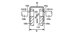
- the pair of connecting holes 102a and 102b need to be provided concentrically with high accuracy, for example, as shown in FIG. 8, a pair of punches 104a and 104b are opposed to each other and are simultaneously processed using a pressing press.
- the present invention has been made against the background of the above circumstances.
- the object of the present invention is to provide a vehicle operating pedal device in which a pair of halves are joined to form a hollow pedal arm. It is intended to be compact, lightweight and inexpensive without being restricted in the degree of freedom of design related to the dimension D, and to prevent deterioration in appearance and injury due to the joint.
- the first invention has a longitudinal hollow pedal arm which is disposed in the vertical direction of the vehicle and in which a pedal seat provided at the lower end portion is stepped on to the front side of the vehicle.
- a vehicular operating pedal device that transmits pedal operating force applied to a pedal arm to an output member connected to the hollow pedal arm so as to be relatively rotatable, (a) A cross section divided into two along the front and rear sides of the vehicle is formed by a pair of U-shaped front and rear halves, which are combined so that the opening sides face each other in the vehicle width direction.
- the side end portions located on both sides are integrally joined to each other to form a hollow cylindrical shape, while (b) the hollow portion having a connecting portion connected to the output member so as to be relatively rotatable.
- the hollow pedal arm has a pair of side end portions of the rear half portion that are respectively outside a pair of side end portions of the front half portion. Are combined and integrally joined so as to overlap each other.
- 3rd invention is the operation pedal device for vehicles of the 1st invention or the 2nd invention.
- a slit-like 1st through-hole and 2nd through-hole in the above-mentioned front half and the above-mentioned half (B) The connecting plate is inserted into the hollow pedal arm in the vehicle front-rear direction through the first through hole and the second through hole, and protrudes to the outside from the hollow pedal arm. Both ends including the connecting portion are integrally fixed to the hollow pedal arm by welding.
- 4th invention is the operation pedal apparatus for vehicles of 1st invention or 2nd invention, (a) The said connection plate is partially inserted in the slit-shaped 1st through-hole provided in the said front half part.
- the connecting portion is integrally fixed to the hollow pedal arm by welding in a state where the connecting portion protrudes from the first through hole to the front side of the vehicle, and (b) the output member connected to the connecting plate includes: A pressing load that pushes the vehicle forward is applied by a pedal operation force.
- 5th invention is the operation pedal apparatus for vehicles of 4th invention, (a) The said rear side half body is provided with the slit-shaped 2nd through-hole corresponding to the said 1st through-hole, (b) The connecting plate includes both ends including the connecting portion that is inserted through the hollow pedal arm in the vehicle front-rear direction through the first through hole and the second through hole and protrudes to the outside from the hollow pedal arm. Are integrally fixed to the hollow pedal arm by welding.
- the fifth invention is an embodiment of the fourth invention, but is also substantially an embodiment of the third invention.
- connection plate is provided with a protrusion protruding in the longitudinal direction of the second through hole at a portion located in the hollow of the hollow pedal arm. It is characterized by being.
- a seventh aspect of the invention is the vehicle operation pedal device according to the fifth aspect of the invention, wherein the connecting portion of the connecting plate protrudes in the longitudinal direction of the first through hole at a portion protruding outward from the first through hole. A protrusion is provided.
- the hollow pedal arm is composed of a pair of front and rear halves divided into two in the vehicle front-rear direction, and is combined so that the opening sides face each other. Since the side end portions located on both sides in the vehicle width direction are integrally joined to each other to form a hollow cylindrical shape, the joined portion is difficult to see from the driver's seat side and the appearance is improved. Injuries to legs and the like are suppressed by the joint. Further, since the output member is connected to the connecting portion of the connecting plate integrally fixed to the hollow pedal arm, compared to the case where the connecting pins are provided by providing the connecting holes on both sides of the hollow pedal arm. Thus, the degree of freedom in designing with respect to the front-rear dimension L and the width dimension D is not restricted, and the hollow pedal arm can be configured in a compact, lightweight and inexpensive manner while ensuring a predetermined connection strength.
- the pair of side end portions of the rear half body are combined and integrally joined so as to overlap the outer sides of the pair of side end portions of the front half body, so that the driver's seat
- the joint portion becomes more difficult to see from the side, the appearance is further improved, and injuries such as feet are more effectively suppressed.
- first through holes and second through holes are provided in the front and rear halves, respectively, and the connecting plate has the first and second through holes. Since the hollow pedal arm is inserted in the vehicle front-rear direction and the both ends including the connecting portion projecting outward from the hollow pedal arm are integrally fixed to the hollow pedal arm by welding, the connecting plate Can be firmly fixed to the hollow pedal arm. Further, since the two positions of the connecting plate are positioned by the first through hole and the second through hole, the mounting posture of the connecting plate with respect to the hollow pedal arm is stabilized and the mounting work (welding) is facilitated.
- the arrangement position of the connecting plate can be set as appropriate, so that the lever ratio of the hollow pedal arm and the offset amount in the vehicle width direction are different.
- the connecting plate can be used in common for a plurality of types of hollow pedal arms, and the cost can be further reduced.
- the connecting plate is partially inserted into a first through hole provided in the front half body, and the connecting portion is integrated with the hollow pedal arm by welding in a state of protruding from the first through hole to the vehicle front side. Since the position of the connecting plate can be appropriately set by changing the position of the first through hole, the lever ratio of the hollow pedal arm and the offset amount in the vehicle width direction are different. In addition, the connecting plate can be used in common for a plurality of types of hollow pedal arms, and the cost can be further reduced.
- the rear half body is provided with a second through hole corresponding to the first through hole, and the connecting plate passes through the first through hole and the second through hole, and the hollow pedal is provided.
- the arm is inserted in the vehicle longitudinal direction, and both ends including the connecting portion projecting outward from the hollow pedal arm are integrally fixed to the hollow pedal arm by welding, so that the connecting plate is firmly fixed to the hollow pedal. Can be fixed to the arm. Further, since the two positions of the connecting plate are positioned by the first through hole and the second through hole, the mounting posture of the connecting plate with respect to the hollow pedal arm is stabilized and the mounting work (welding) is facilitated.
- the protrusion that protrudes in the longitudinal direction of the second through hole is provided in the portion of the connecting plate that is located in the hollow of the hollow pedal arm, the welding for joining the connecting plate to the hollow pedal arm is peeled off. Even in this case, the protrusion is prevented from coming out of the second through hole by the protrusion coming into contact with the inner wall surface of the rear half in the vicinity of the end portion in the longitudinal direction of the second through hole. Thus, the pedal operating force is transmitted to the output member.
- the connecting plate since the protrusion of the connecting plate that protrudes outward from the first through hole is provided with a protrusion protruding in the longitudinal direction of the first through hole, the connecting plate is joined to the hollow pedal arm. Even when the welding to be peeled off, the projection is brought into contact with the outer wall surface of the front half in the vicinity of the longitudinal end of the first through hole, so that the connection plate is prevented from entering the first through hole. Pedal operating force is transmitted to the output member via the connecting plate.
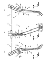
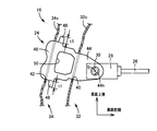
- FIG. 1 is a perspective view showing a vehicle operation pedal device according to an embodiment of the present invention. It is a figure which shows the operation pedal of the operation pedal apparatus for vehicles of FIG. 1, (a) is a left view, (b) is a front view seen from the driver's seat side, (c) is a right view.
- FIG. 3 is an enlarged cross-sectional view of a cross-section portion along the line III-III in FIG. 2.
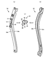
- FIG. 4 is an enlarged cross-sectional view of a IV-IV cross-sectional portion in FIG. 2. It is the perspective view shown with the connection plate in the state before joining a pair of halves which comprise the hollow pedal arm of the operation pedal apparatus for vehicles of FIG.
- the present invention is preferably applied to a vehicle operation pedal device for a service brake or a parking brake to which a relatively large pedal operation force is applied, but can also be applied to an accelerator pedal device, a clutch pedal device, or the like.
- the hollow pedal arm is disposed in the vertical direction of the vehicle, but is not necessarily in a completely vertical state, and may be inclined in the front-rear direction.
- the lower end portion where the pedal seat is provided is on the driver's seat side ( It is generally arranged in a posture inclined to the rear side of the vehicle, and is supported at the upper end portion so as to be swingable around a support axis substantially parallel to the vehicle width direction.
- the hollow pedal arm is composed of a pair of front and rear halves having a U-shaped cross section that is divided into a vehicle front side and a rear side along the longitudinal direction.
- the cross-sectional shape may be an angular U-shape (U-shape), a semicircular shape or a semi-elliptical shape, or a hat cross-sectional shape having a flange-like flange bent outward at a side edge on the opening side.
- the side ends located on both sides in the vehicle width direction are joined together so that the opening sides face each other. For example, the side ends of both halves are overlapped, and arc welding or the like is performed. It can be joined by welding means, or can be joined by other joining means such as an adhesive.
- the side edge of the opening side can be butted together and joined by arc welding, and in the case of a hat cross-section, the flange can be mechanically joined by clinching or caulking, etc.
- This joining is desirably performed continuously in the longitudinal direction of the hollow pedal arm, but may be performed only intermittently.
- a metal plate such as a steel plate
- a connection plate is integrally fixed to the hollow pedal arm, and an output member is connected to the hollow pedal arm through a connection pin or the like so as to be relatively rotatable around a connection axis parallel to the support axis, for example.
- a brake booster push rod, a connecting link that connects the intermediate lever and the hollow pedal arm, or a reaction force member of a simulation device that applies a reaction force to the operation pedal to electrically detect the pedal operation force, etc. is there.
- the connecting plate is disposed, for example, at an intermediate portion between the support shaft center of the hollow pedal arm and the pedal seat so that the connecting portion protrudes toward the front side of the vehicle, that is, the stepping direction side of the hollow pedal arm.
- the output member to be connected is configured to be pressed toward the front side of the vehicle.
- the output member can be pulled in accordance with the pedal operation, and the location of the connection plate is appropriately determined.
- the connecting portion is removed from the second through hole provided in the rear half.
- the protrusion provided on the connection plate protrudes toward the rear side of the vehicle and protrudes into a portion located inside the second through hole or outside the first through hole so that the connection plate does not come out of the second through hole.
- the connecting plate is formed in a flat plate located in a single plane, but is partially inserted into a slit-like through hole provided in the hollow pedal arm in the vehicle vertical direction (perpendicular to the support axis).
- the connecting portion When the connecting portion is disposed so as to protrude from the through hole to the outside, the portion protruding from the through hole may be bent into a crank shape, or be bent into an L shape and be in front of the hollow pedal arm.
- Various modes are possible, such as being able to be welded and fixed to the wall portion and the rear wall portion.
- the connecting portion of the connecting plate is configured to be flat, for example, so as to be located in a plane perpendicular to the support axis of the hollow pedal arm, and a connecting hole is provided in parallel with the support axis, via a connecting pin.
- the output member is coupled so as to be relatively rotatable.
- This connecting plate is also preferably made of a metal plate (steel plate, etc.) that can be welded, and is integrally fixed to the hollow pedal arm by welding means such as arc welding. It is also possible to fix with the fixing means.
- the pair of side end portions of the rear half body are combined so that they are overlapped with the outside of the pair of side end portions of the front half body.
- the pair of side end portions of the split body may be combined so as to be overlapped inside the pair of side end portions of the front half portion, or one may be overlapped inside and the other overlapped outside.
- These side end portions can be joined by welding such as arc welding, for example, but if the connecting plate is a metal material that can be welded, it is possible to weld the connecting plate to the hollow pedal arm continuously, Productivity is improved and manufacturing costs can be further reduced.
- the connecting plate is fixed by welding in a state of being partially inserted into the slit-like first through hole provided in the front half body.
- the connecting plate can be integrally fixed to the outer wall surface of the hollow pedal arm by arc welding or the like without providing a through hole in the split body.
- the rear half body is also provided with slit-like second through holes corresponding to the first through holes, and the connecting plate penetrates both the first through holes and the second through holes.
- the hollow pedal arm can be attached to the hollow pedal arm in a state where, for example, the connecting plate is brought into contact with the inner wall surface of the rear half body without providing the second through hole in the rear half body. It may be fixed.
- the connecting plate When the connecting plate is allowed to penetrate both the first through hole and the second through hole as in the fifth invention, the connecting plate may be inserted from either side of the first through hole or the second through hole.
- the connecting plate Before connecting the front half and the rear half integrally, the connecting plate is arranged between the two, and both ends of the connecting plate are respectively outward from the first through hole and the second through hole. A pair of halves may be joined in a protruding state. Even when a through hole for attaching the connecting plate is provided only in one of the half halves, the connecting plate is arranged in one half so that the connecting portion protrudes from the through hole, and the other half You may make it join integrally by combining a split body. In any case, after joining a pair of halves to form a hollow pedal arm, the connecting plate may be inserted from the first through hole or the second through hole and welded to the hollow pedal arm.
- a projection is provided in a portion of the connecting plate located in the hollow of the hollow pedal arm, and even when the welding is peeled off, the projection abuts in the vicinity of the end portion in the longitudinal direction of the second through hole, Although the connecting plate is prevented from coming out of the second through hole, such a protrusion is not necessarily required when implementing other inventions.
- the protrusion is preferably provided as close to the second through hole as possible.
- the protrusion can be provided so as to contact the rear wall portion of the rear half body, but at least in the portion located in the hollow of the hollow pedal arm. It only has to be provided.
- the protrusion dimension of the protrusion is determined as appropriate so that the connecting plate does not come out of the second through hole, and is set according to the gap dimension between the second through hole and the connecting plate, for example. Specifically, it is desirable that the protrusion dimensions of the protrusions on both sides are larger than the gap dimension.
- the projection of the seventh invention is different from the projection of the sixth invention in that it is provided at a portion protruding from the first through hole in the connecting portion of the connecting plate. It is appropriately determined in the same manner as the projection of the sixth invention.
- FIG. 1 is a perspective view showing a vehicle operation pedal device 10 to which the present invention is applied.
- the vehicle operation pedal device 10 is a brake pedal device for a service brake.
- the operation pedal 12 swings on a bracket 14 that is integrally fixed to a vehicle body. It is arranged to be movable.
- 2A and 2B are diagrams for explaining the operation pedal 12.
- FIG. 2A is a left side view
- FIG. 2B is a front view seen from the driver's seat side
- FIG. 2C is a right side view.
- 3 is an enlarged cross-sectional view taken along the line III-III in FIG. 2 (a)
- FIG. 4 is an enlarged cross-sectional view taken along the line IV-IV in FIG. 2 (b).
- the operation pedal 12 includes a longitudinal hollow pedal arm 16 disposed in the vertical direction of the vehicle, and a pedal seat 18 fixed to the lower end of the hollow pedal arm 16 and operated by a driver. Yes.
- the hollow pedal arm 16 is arranged in such a posture that the lower end portion where the pedal seat 18 is provided is inclined toward the driver's seat side, that is, the vehicle rear side, and the upper end portion has a cylindrical collar so as to penetrate in the vehicle width direction.
- 20 is integrally fixed, and is supported by a support shaft 22 provided on the bracket 14 so as to penetrate through the collar 20 so as to be rotatable around an axis O of the support shaft 22.
- the axis O of the support shaft 22 is a support axis. 1 and 2 both show the initial position before the operation pedal 12 is depressed.
- a connecting plate 24 is integrally fixed so as to protrude toward the front side of the vehicle at an intermediate portion of the hollow pedal arm 16, that is, below the collar 20 and above the center in the vertical direction.
- the output member 26 can rotate relative to the connection plate 24 around a connection axis S parallel to the support axis O via a bifurcated (U-shaped) clevis 28 and a clevis pin 30.
- the pedal operation force applied to the operation pedal 12 is transmitted from the connection plate 24 to the output member 26 via the clevis pin 30 and is pressed to the front side of the vehicle.
- the output member 26 is a push rod of a brake booster, for example, and generates a braking force corresponding to the pedal operation force when pressed to the vehicle front side.
- the connection axis S is the axis of the clevis pin 30 and the clevis pin 30 corresponds to the connection pin.
- the hollow pedal arm 16 includes a pair of a front half 32 and a rear half 34 that are divided into a vehicle front side and a rear side along the longitudinal direction.
- FIG. 5 is a perspective view showing the connecting plate 24 and the halves 32 and 34 before welding a pair of the front halves 32 and the rear halves 34.
- Each of the possible metal plate materials is bent by a press, and each has a U-shaped cross section. Then, the U-shaped opening sides are combined in a posture to face each other, and the side end portions 32a and 34a, 32b and 34b located on both sides in the vehicle width direction are integrally joined to each other, so that a closed cross section is obtained. It has a hollow rectangular tube shape (right-angled quadrilateral). In this embodiment, as apparent from FIG.
- the pair of side end portions 34 a and 34 b of the rear half body 34 are superimposed on the outside of the pair of side end portions 32 a and 32 b of the front half body 32, respectively.
- the fillet welding is performed by welding means such as arc welding continuously in the longitudinal direction along the edges of the side end portions 34a and 34b, so that the pair of halves 32 and 34 are integrated.
- the hollow pedal arm 16 is configured by being joined to each other.
- the first welded portion W1 in FIGS. 1, 2 and 3 is a welded portion of the side end portions 32a and 34a or a welded portion of the side end portions 32b and 34b.
- the connecting plate 24 is made of a weldable metal plate such as a flat steel plate thicker than the halves 32 and 34 in order to ensure a predetermined strength capable of transmitting pedal operating force.
- the front wall portion 32c of the front half body 32 and the rear wall portion 34c of the rear half body 34 are each provided with a slit-like first through hole 40 in a straight line in the direction perpendicular to the support axis O, that is, in the vertical direction.
- Two through holes 42 are provided, and the connecting plate 24 is disposed so as to penetrate the hollow pedal arm 16 in the vehicle front-rear direction through the first through hole 40 and the second through hole 42. Yes.
- the first through hole 40 and the second through hole 42 are each provided with a width dimension substantially equal to the plate thickness of the connection plate 24 and have a length dimension slightly larger than the width dimension of the connection plate 24.
- the second weld W2 in FIG. 3 is a weld between the connection plate 24 and the front half 32
- the third weld W3 in FIGS. 1, 2 and 3 is the connection plate 24 and the rear half. This is a welded portion with the body 34.
- the connecting plate 24 has a flat plate shape so that the whole is located in a single plane.
- the connecting plate 24 penetrates the first through hole 40 and the second through hole 42, so And is fixed to the hollow pedal arm 16 in a posture positioned within a substantially perpendicular plane.
- the second through hole 42 is provided corresponding to the first through hole 40 so that the connecting plate 24 is disposed in one plane substantially perpendicular to the support axis O, and the first through hole 40 is provided.
- the position of the hole 40 is appropriately determined according to the lever ratio of the operation pedal 12 set for each vehicle and the offset amount in the vehicle width direction.
- the connecting plate 24 includes a connecting portion 44 that protrudes to the outside from the first through hole 40 and a protruding portion 46 that protrudes to the outside from the second through hole 42, and the connecting portion 44 is provided with a connecting hole 44 h.
- the clevis pin 30 is inserted through a bearing or the like.
- the proximal end side of the protrusion 46 that is, the portion located in the hollow of the hollow pedal arm 16 and the portion close to the rear wall portion 34 c of the rear half 34 is provided in the longitudinal direction of the second through hole 42.
- a pair of protrusions 48 are provided so as to protrude to both sides.
- the protrusion dimensions t1 of these protrusions 48 are both larger than the gap dimension between the second through hole 42 and the protrusion 46 (the length dimension of the second through hole 42 ⁇ the width dimension of the protrusion 46). Even when both the second welded portion W2 and the third welded portion W3 are peeled off, the connecting plate 24 may come out of the second through hole 42 by the protrusion 48 being brought into contact with the inner wall surface of the rear wall portion 34c. The pedal operation force is reliably transmitted to the output member 26 via the connecting plate 24. In a state where the connecting plate 24 is fixed to the hollow pedal arm 16, it is possible to provide a protrusion 48 so as to contact the rear wall portion 34 c of the rear half 34.
- the connecting plate 24 is arranged between the front half 32 and the rear half 34 before they are integrally joined, and the connecting portion 44 is arranged between the front half and the front half. While being fitted into the first through hole 40 from the inside of the body 32, the protruding portion 46 is fitted into the second through hole 42 from the inside of the rear half body 34.
- the side end portions 32a and 32b of the front half body 32 and the side end portions 34a and 34b of the rear half body 34 are combined so as to overlap each other, and the side end portions 32a and 34a, 32b and 34b are welded by welding means such as arc welding, and the connecting portion 44 and the protruding portion 46 of the connecting plate 24 are continuously connected to the front wall 32c of the front half 32 and the rear half 34, respectively. It welds to the wall part 34c.
- the hollow pedal arm 16 in which the connecting plate 24 is integrally fixed by welding is obtained, and the operation pedal 12 is obtained by further fixing the collar 20 and the pedal seat 18 integrally by welding or the like. .
- the connecting plate 24 is extracted in the central portion located in the hollow pedal arm 16 and away from the second welded portion W2 and the third welded portion W3.
- a hole 50 is provided.
- the hollow pedal arm 16 is curved smoothly so that the middle portion in the longitudinal direction where the connecting plate 24 is disposed bulges toward the rear side of the vehicle.
- An intermediate portion, that is, a portion where the connecting plate 24 is fixed is provided with a recess 52 that is indented and deformed inward, and the upper and lower portions of the recess 52 are partially outside (rear of the vehicle) by drawing or the like.
- Convex portion 54 is provided so as to protrude and deform to the side), and a predetermined strength is ensured while maintaining a light weight due to the thin wall.
- the hollow pedal arm 16 is composed of a pair of a front half body 32 and a rear half body 34 that are divided into two in the vehicle front-rear direction.
- the side end portions 32a and 34a, 32b and 34b, which are combined so that the opening sides face each other and located on both sides in the vehicle width direction, are integrally joined to form a hollow cylindrical shape. Since the joint (the first welded portion W1) becomes difficult to be seen and the appearance is improved, the joint is prevented from being injured by the joint.
- the coupling holes 102 a are formed on the left and right sides as in the hollow pedal arm 100 of FIG. 7.
- the design freedom regarding the front-rear dimension L and the width dimension D is not restricted, and the hollow pedal arm 16 is compact while ensuring a predetermined connection strength. And can be configured to be lightweight and inexpensive.
- the pair of side end portions 34a and 34b of the rear half body 34 are combined so as to be superimposed on the outside of the pair of side end portions 32a and 32b of the front side half body 32, respectively. Since 34a, 32b, and 34b are integrally joined by fillet welding, the joint becomes more difficult to see from the driver's seat side, the appearance is further improved, and injuries such as feet are more effectively suppressed. .
- the connecting plate 24 can be continuously fixed to the hollow pedal arm 16 by welding at the same time, thereby improving productivity. Manufacturing costs can be further reduced.
- the connecting plate 24 passes the hollow pedal arm 16 in the vehicle front-rear direction through the first through hole 40 provided in the front half body 32 and the second through hole 42 provided in the rear half body 34.
- the first through hole 40 and the second through hole 42 are inserted and fixed integrally to the hollow pedal arm 16 by welding with the connecting portion 44 protruding from the first through hole 40 toward the vehicle front side.
- the arrangement position of the connecting plate 24 can be set as appropriate, and can be easily diverted to vehicles having different lever ratios of the hollow pedal arm 16 and offset amounts in the vehicle width direction.
- the connecting plate 24 can be made common to the hollow pedal arm 16, and the cost can be further reduced.
- the connecting plate 24 includes a connecting portion 44 protruding outward from the first through hole 40 and a protruding portion 46 protruding outward from the second through hole 42 by a fillet weld, respectively. Since the connecting plate 24 is firmly fixed to the hollow pedal arm 16 because it is integrally fixed to the body 34, two positions of the connecting plate 24 are positioned by the first through hole 40 and the second through hole 42. Therefore, the mounting posture of the connecting plate 24 with respect to the hollow pedal arm 16 is stabilized and the mounting operation (welding) is facilitated.
- a protrusion 48 protruding in the longitudinal direction of the second through hole 42 is provided in a portion of the connection plate 24 located in the hollow of the hollow pedal arm 16, and the connection plate 24 is fixed to the hollow pedal arm 16. Even when both the second welded portion W2 and the third welded portion W3 to be peeled off, the projection 48 abuts on the inner wall surface of the rear wall portion 34c in the vicinity of the end portion in the longitudinal direction of the second through hole 42, thereby connecting the connection plate. 24 is prevented from coming out of the second through hole 42, so that the pedal operating force is reliably transmitted to the output member 26 through the connection plate 24.
- the pair of protrusions 48 are provided on both sides of the connecting plate 24, the posture of the connecting plate 24 is prevented from changing greatly, and the pedal operating force is appropriately adjusted via the connecting plate 24. It is transmitted to the output member 26.
- the projection 48 is provided on the portion of the connecting plate 24 located in the hollow of the hollow pedal arm 16, but on both sides of the connecting portion 44 as in the connecting plate 60 shown in FIG. 6.
- Protrusions 62 can also be provided. That is, a pair of protrusions 62 are provided in a portion protruding outward from the first through hole 40 and in a portion adjacent to the front wall portion 32c of the front half body 32 so as to protrude in the longitudinal direction of the first through hole 40. May be.
- the protrusion dimension t2 of these protrusions 62 is larger than the gap dimension between the first through hole 40 and the connecting portion 44 (the length dimension of the first through hole 40 minus the width dimension of the connecting portion 44).
- the protrusion 62 is in front of the first through hole 40 in the vicinity of the end portion in the longitudinal direction.
- the contact of the connecting plate 60 with the outer wall surface of the wall portion 32 c prevents the first through hole 40 from being immersed, and the pedal operation force is reliably transmitted to the output member 26 via the connecting plate 60.
- the pair of protrusions 62 are provided on both sides of the connecting plate 60, the posture of the connecting plate 60 is prevented from changing greatly, and the pedal operating force is appropriately applied to the output member 26 via the connecting plate 60. Communicated.
- connection plate 60 of FIG. 6 is different from the connection plate 24 only in the protrusion 62, and the other parts are substantially the same as the connection plate 24. Omitted.
Landscapes
- Engineering & Computer Science (AREA)
- Physics & Mathematics (AREA)
- General Physics & Mathematics (AREA)
- Automation & Control Theory (AREA)
- Manufacturing & Machinery (AREA)
- Mechanical Control Devices (AREA)
- Braking Elements And Transmission Devices (AREA)
Description
本発明は車両用操作ペダル装置に係り、特に、断面がU字形状の一対の半割体を接合して中空ペダルアームが構成される車両用操作ペダル装置の改良に関するものである。
車両の上下方向に配設され、下端部に設けられたペダルシートが車両前側へ踏込み操作される長手状の中空ペダルアームを有し、その中空ペダルアームに加えられたペダル操作力を、その中空ペダルアームに相対回動可能に連結される出力部材に伝達する車両用操作ペダル装置が知られている。特許文献1に記載の装置はその一例で、中空ペダルアームは、車両幅方向に2分割された断面がU字形状(浅いコの字形状乃至は皿形状)の一対の半割体にて構成されており、開口側が対向するように組み合わされて車両前後方向の両側に位置する側端部が互いに一体的に接合されることにより中空の筒形状とされている。また、一対の半割体にはそれぞれ連結穴が設けられ、両方の連結穴を貫通するように連結ピンが配設されて、出力部材である連結リンクやプッシュロッドがその連結ピンの軸心(連結軸心)まわりに相対回動可能に連結されている。
しかしながら、このように中空ペダルアームを車両幅方向に2分割した構造の車両用操作ペダル装置においては、車両前後方向の両側に接合部が位置し、その車両後側の接合部が運転席側から見えるため見栄えが悪いとともに、誤って足や手が接合部に触れると怪我する可能性があった。
これに対し、未だ公知ではないが、上記中空ペダルアームを車両前後方向に2分割し、車両幅方向の両側に位置する側端部を一体的に接合して中空の筒形状とすることが考えられる。図7の中空ペダルアーム100はその一例で、長手方向と直角に切断した断面図であり、断面U字形状の一対の前側半割体32および後側半割体34にて構成されているとともに、車両幅方向の両側に位置する側端部32aおよび34a、32bおよび34bがそれぞれ溶接により一体的に接合されている。その場合に、出力部材を連結するためのクレビスピン30を挿通させる連結穴102a、102bを一対の半割体32、34の接合部に設けると、中空ペダルアーム100の強度低下の原因になるため、例えば前側半割体32の側壁部に設けられるが、前後寸法Lが大きくなり、重量が大きくなったり製造コストが高くなったりする。また、一対の連結穴102a、102bは、高い精度で同心に設ける必要があるため、例えば図8に示すように一対のパンチ104a、104bが対向して配置された寄せ型プレスを用いて同時に加工することが望ましいが、一対のダイス106a、106bや、スクラップ108を落下させるための排出通路110を前側半割体32の一対の側壁の内側に設ける必要があり、幅寸法Dが大きくなって、この点でも重量増やコスト高の原因になる。二股状のクレビスを用いて出力部材を連結する場合、幅寸法Dの増加により汎用のクレビスを使用できなくなり、製造コストが一層高くなる可能性もある。
本発明は以上の事情を背景として為されたもので、その目的とするところは、一対の半割体を接合して中空ペダルアームが構成される車両用操作ペダル装置において、前後寸法Lや幅寸法Dに関する設計の自由度が制約されることなくコンパクトで軽量且つ安価に構成できるとともに、接合部による見栄えの悪化や怪我が抑制されるようにすることにある。
かかる目的を達成するために、第1発明は、車両の上下方向に配設され、下端部に設けられたペダルシートが車両前側へ踏込み操作される長手状の中空ペダルアームを有し、その中空ペダルアームに加えられたペダル操作力を、その中空ペダルアームに相対回動可能に連結される出力部材に伝達する車両用操作ペダル装置において、(a) 前記中空ペダルアームは、上下の長手方向に沿って車両前側および後側に2分割された断面がU字形状の一対の前側半割体および後側半割体にて構成されており、開口側が対向するように組み合わされて車両幅方向の両側に位置する側端部が互いに一体的に接合されることにより中空の筒形状とされている一方、(b) 前記出力部材に相対回動可能に連結される連結部を有して前記中空ペダルアームに一体的に固設された板状の連結プレートを備えていることを特徴とする。
第2発明は、第1発明の車両用操作ペダル装置において、前記中空ペダルアームは、前記後側半割体の一対の側端部が、それぞれ前記前側半割体の一対の側端部の外側に重ね合わされるように組み合わされて一体的に接合されていることを特徴とする。
第3発明は、第1発明または第2発明の車両用操作ペダル装置において、(a) 前記前側半割体および前記後側半割体にはそれぞれスリット状の第1貫通穴および第2貫通穴が設けられており、(b) 前記連結プレートは、前記第1貫通穴および前記第2貫通穴を通って前記中空ペダルアームを車両前後方向に挿通させられ、その中空ペダルアームから外部に突き出す前記連結部を含む両端部がそれぞれ溶接によりその中空ペダルアームに一体的に固設されていることを特徴とする。
第4発明は、第1発明または第2発明の車両用操作ペダル装置において、(a) 前記連結プレートは、前記前側半割体に設けられたスリット状の第1貫通穴内に部分的に挿入され、前記連結部がその第1貫通穴から車両前側へ突き出す状態で溶接により前記中空ペダルアームに一体的に固設されており、(b) その連結プレートに連結される前記出力部材には、前記ペダル操作力により車両前側へ押し出す押圧荷重が加えられることを特徴とする。
第5発明は、第4発明の車両用操作ペダル装置において、(a) 前記後側半割体には、前記第1貫通穴に対応してスリット状の第2貫通穴が設けられており、(b) 前記連結プレートは、前記第1貫通穴および前記第2貫通穴を通って前記中空ペダルアームを車両前後方向に挿通させられ、その中空ペダルアームから外部に突き出す前記連結部を含む両端部がそれぞれ溶接によりその中空ペダルアームに一体的に固設されていることを特徴とする。
この第5発明は、第4発明の一実施態様であるが、実質的に前記第3発明の一実施態様でもある。
この第5発明は、第4発明の一実施態様であるが、実質的に前記第3発明の一実施態様でもある。
第6発明は、第5発明の車両用操作ペダル装置において、前記連結プレートには、前記中空ペダルアームの中空内に位置する部分に、前記第2貫通穴の長手方向へ突き出す突起が設けられていることを特徴とする。
第7発明は、第5発明の車両用操作ペダル装置において、前記連結プレートの前記連結部であって、前記第1貫通穴から外側へ突き出す部分には、その第1貫通穴の長手方向へ突き出す突起が設けられていることを特徴とする。
このような車両用操作ペダル装置においては、中空ペダルアームが車両前後方向に2分割された一対の前側半割体および後側半割体にて構成されており、開口側が対向するように組み合わされて車両幅方向の両側に位置する側端部が互いに一体的に接合されることにより中空の筒形状とされているため、運転席側からはその接合部が見え難くなって見栄えが向上するとともに、接合部によって足等を怪我することが抑制される。また、中空ペダルアームに一体的に固設された連結プレートの連結部に出力部材が連結されるため、中空ペダルアームの両側部に連結穴を設けて連結ピン等を配設する場合に比較して、前記前後寸法Lや幅寸法Dに関する設計の自由度が制約されることがなく、所定の連結強度を確保しつつ中空ペダルアームをコンパクトで軽量且つ安価に構成できる。
第2発明では、後側半割体の一対の側端部がそれぞれ前側半割体の一対の側端部の外側に重ね合わされるように組み合わされて一体的に接合されているため、運転席側から接合部が一層見え難くなり、見栄えが更に向上するとともに足等の怪我が一層効果的に抑制される。
第3発明では、前側半割体および後側半割体にそれぞれスリット状の第1貫通穴および第2貫通穴が設けられており、連結プレートはそれ等の第1貫通穴および第2貫通穴を通って中空ペダルアームを車両前後方向に挿通させられ、その中空ペダルアームから外部に突き出す前記連結部を含む両端部がそれぞれ溶接により中空ペダルアームに一体的に固設されているため、連結プレートを強固に中空ペダルアームに固設することができる。また、第1貫通穴および第2貫通穴によって連結プレートの2箇所が位置決めされるため、中空ペダルアームに対する連結プレートの取付姿勢が安定するとともに取付作業(溶接)が容易になる。また、第1貫通穴および第2取付穴の位置を変更することにより連結プレートの配設位置を適宜設定することが可能で、中空ペダルアームのレバー比や車両幅方向のオフセット量が異なる車両にも容易に転用できるとともに、複数種類の中空ペダルアームに対して連結プレートを共通化することが可能で、更なるコストダウンを図ることができる。
第4発明では、連結プレートが前側半割体に設けられた第1貫通穴内に部分的に挿入され、連結部がその第1貫通穴から車両前側へ突き出す状態で溶接により中空ペダルアームに一体的に固設されているため、第1貫通穴の位置を変更することにより連結プレートの配設位置を適宜設定することが可能で、中空ペダルアームのレバー比や車両幅方向のオフセット量が異なる車両にも容易に転用できるとともに、複数種類の中空ペダルアームに対して連結プレートを共通化することが可能で、更なるコストダウンを図ることができる。
第5発明では、後側半割体に前記第1貫通穴に対応して第2貫通穴が設けられており、連結プレートはそれ等の第1貫通穴および第2貫通穴を通って中空ペダルアームを車両前後方向に挿通させられ、その中空ペダルアームから外部に突き出す前記連結部を含む両端部がそれぞれ溶接により中空ペダルアームに一体的に固設されているため、連結プレートを強固に中空ペダルアームに固設することができる。また、第1貫通穴および第2貫通穴によって連結プレートの2箇所が位置決めされるため、中空ペダルアームに対する連結プレートの取付姿勢が安定するとともに取付作業(溶接)が容易になる。
第6発明では、連結プレートのうち中空ペダルアームの中空内に位置する部分に、第2貫通穴の長手方向へ突き出す突起が設けられているため、連結プレートを中空ペダルアームに接合する溶接が剥がれた場合でも、第2貫通穴の長手方向の端部近傍の後側半割体の内壁面に突起が当接することにより連結プレートが第2貫通穴から抜け出すことが防止され、その連結プレートを介して出力部材にペダル操作力が伝達される。
第7発明では、連結プレートの連結部であって第1貫通穴から外側へ突き出す部分に、その第1貫通穴の長手方向へ突き出す突起が設けられているため、連結プレートを中空ペダルアームに接合する溶接が剥がれた場合でも、第1貫通穴の長手方向の端部近傍の前側半割体の外壁面に突起が当接することにより連結プレートが第1貫通穴内に没入することが防止され、その連結プレートを介して出力部材にペダル操作力が伝達される。
本発明は、比較的大きなペダル操作力が加えられる常用ブレーキ用或いは駐車ブレーキ用の車両用操作ペダル装置に好適に適用されるが、アクセルペダル装置やクラッチペダル装置等にも適用され得る。中空ペダルアームは、車両の上下方向に配設されるが、必ずしも完全な垂直状態である必要はなく、前後方向に傾斜していても良く、例えばペダルシートが設けられる下端部が運転席側(車両後側)へ傾斜する姿勢で配設され、上端部において車両幅方向と略平行な支持軸心まわりに揺動可能に支持されるのが一般的である。また、必ずしも一直線である必要はなく、車両の前後方向或いは左右方向へ曲げられていても良いなど、全体として上下方向の成分を含んで配設されるものであれば良い。
中空ペダルアームは、上下の長手方向に沿って車両前側および後側に2分割された断面がU字形状の一対の前側半割体および後側半割体にて構成されるが、U字形の断面形状は角張ったU字形状(コの字形状)でも、半円形状や半楕円形状でも良く、開口側の側端縁に外側へ曲げられた鍔状のフランジを有するハット断面形状でも良い。そして、開口側が対向するように組み合わされて車両幅方向の両側に位置する側端部が互いに一体的に接合されるが、例えば両方の半割体の側端部を重ね合わせてアーク溶接等の溶接手段で接合できるし、接着剤等の他の接合手段で接合することも可能である。また、開口側の側端縁を突き合わせてアーク溶接などで接合することもできるし、ハット断面形状の場合、フランジをクリンチ加工やかしめ加工などで機械的に接合することもできるなど、種々の接合態様が可能である。この接合は、中空ペダルアームの長手方向に連続的に行うことが望ましいが、断続的に行うだけでも良い。一対の半割体としては、溶接が可能な金属製の板材(鋼板など)が好適に用いられ、プレス加工によって断面U字形状に成形することが望ましい。
上記中空ペダルアームには連結プレートが一体的に固設され、連結ピン等を介して例えば支持軸心と平行な連結軸心まわりに相対回動可能に出力部材が連結されるが、出力部材は、例えばブレーキブースタのプッシュロッドや、中間レバーと中空ペダルアームとを連結する連結リンク、或いはペダル操作力を電気的に検出するために操作ペダルに反力を付与するシミュレーション装置の反力部材などである。連結プレートは、例えば中空ペダルアームの支持軸心とペダルシートとの間の中間部分に、連結部が車両前側すなわち中空ペダルアームの踏込み方向側へ突き出すように配設され、連結ピン等を介して連結される出力部材を車両前側へ押圧するように構成されるが、ペダル操作に伴って出力部材が引っ張られるように構成することも可能で、連結プレートの配設場所は適宜定められる。第4発明~第7発明は、ペダル操作に伴って出力部材に押圧荷重が加えられる場合で、引張荷重が加えられる場合は、例えば後側半割体に設けられる第2貫通穴から連結部を車両後側へ突出させるとともに、連結プレートに設ける突起は、連結プレートがその第2貫通穴から外部へ抜け出さないように、第2貫通穴の内側や第1貫通穴の外側に位置する部分に突設される。なお、中空ペダルアームの支持軸心よりも車両上方側に連結プレートを配設することも可能である。
連結プレートは、例えば単一の平面内に位置する平板状に構成されるが、中空ペダルアームに車両上下方向(支持軸心と直角方向)に設けられたスリット状の貫通穴内に部分的に挿入され、連結部がその貫通穴から外部に突き出すように配設される場合、その貫通穴から突き出す部分でクランク状に曲げられていても良いし、L字形状に曲げられて中空ペダルアームの前壁部や後壁部に溶接固定することもできるなど、種々の態様が可能である。連結プレートの連結部は、例えば中空ペダルアームの支持軸心と直角な平面内に位置するように平坦に構成されるとともに、その支持軸心と平行に連結穴が設けられ、連結ピンを介して出力部材が相対回動可能に連結される。この連結プレートも、溶接が可能な金属製の板材(鋼板など)が好適に用いられ、アーク溶接等の溶接手段で中空ペダルアームに一体的に固設されるが、ねじや接着剤等の他の固設手段で固設することも可能である。
第2発明では、後側半割体の一対の側端部が前側半割体の一対の側端部の外側に重ね合わされるように組み合わされるが、他の発明の実施に際しては、後側半割体の一対の側端部が前側半割体の一対の側端部の内側に重ね合わされるように組み合わされても良いし、一方は内側で他方は外側に重ね合わされるようにしても良い。それ等の側端部は、例えばアーク溶接等の溶接によって接合できるが、連結プレートが溶接可能な金属材料であれば、同時に連続して連結プレートを中空ペダルアームに溶接することが可能であり、生産性が向上して製造コストを一層低減できる。
第4発明では、連結プレートが前側半割体に設けられたスリット状の第1貫通穴内に部分的に挿入された状態で溶接により固設されているが、他の発明の実施に際しては、半割体に貫通穴を設けることなく、中空ペダルアームの外壁面に連結プレートをアーク溶接等により一体的に固設することもできる。第5発明では、後側半割体にも上記第1貫通穴に対応してスリット状の第2貫通穴が設けられ、連結プレートがそれ等の第1貫通穴および第2貫通穴を共に貫通させられているが、第4発明では、後側半割体に第2貫通穴を設けることなく、例えば連結プレートが後側半割体の内壁面に当接させられた状態で中空ペダルアームに固設するようにしても良い。第5発明のように連結プレートが第1貫通穴および第2貫通穴を共に貫通させられる場合、連結プレートはそれ等の第1貫通穴および第2貫通穴のどちら側から挿入されても良いし、前側半割体および後側半割体を一体的に接合する前に連結プレートを両者の間に配置して、その連結プレートの両端部がそれぞれ第1貫通穴および第2貫通穴から外側へ突き出す状態で一対の半割体を接合するようにしても良い。連結プレートを取り付けるための貫通穴が何れか一方の半割体のみに設けられる場合も、連結部がその貫通穴から突き出すように連結プレートを一方の半割体に配置した状態で、他方の半割体を組み合わせて一体的に接合するようにしても良い。なお、何れの場合も、一対の半割体を接合して中空ペダルアームとした後に、第1貫通穴或いは第2貫通穴から連結プレートを挿入して中空ペダルアームに溶接しても良い。
第6発明では、連結プレートのうち中空ペダルアームの中空内に位置する部分に突起が設けられ、溶接が剥がれた場合でもその突起が第2貫通穴の長手方向の端部近傍に当接して、連結プレートが第2貫通穴から抜け出さないようになっているが、他の発明の実施に際してはこのような突起は必ずしも必要ない。突起は、できるだけ第2貫通穴に近接した部分に設けることが望ましく、例えば後側半割体の後壁部に接するように設けることもできるが、少なくとも中空ペダルアームの中空内に位置する部分に設けられれば良い。また、第2貫通穴の長手方向の両端部すなわち連結プレートの両側部に設けることが望ましいが、何れか一方の側部に設けるだけでも良い。突起の突出寸法は、連結プレートが第2貫通穴から抜け出さないように適宜定められ、例えば第2貫通穴と連結プレートとの間の隙間寸法に応じて設定される。具体的には、両側の突起の突出寸法が何れも隙間寸法よりも大きいことが望ましい。第7発明の突起は、連結プレートの連結部であって第1貫通穴から外側へ突き出す部分に設けられる点が、上記第6発明の突起と相違するが、その突起を設ける位置や突出寸法は第6発明の突起と同様にして適宜定められる。
以下、本発明の実施例を、図面を参照しつつ詳細に説明する。
図1は、本発明が適用された車両用操作ペダル装置10を示す斜視図で、常用ブレーキ用のブレーキペダル装置であり、車体に一体的に固設されるブラケット14には操作ペダル12が揺動可能に配設される。図2は、この操作ペダル12を説明する図で、(a) は左側面図、(b) は運転席側から見た正面図、(c) は右側面図である。また、図3は図2の(a) における III-III 断面部分の拡大断面図で、図4は図2の(b) におけるIV-IV断面部分の拡大断面図である。
図1は、本発明が適用された車両用操作ペダル装置10を示す斜視図で、常用ブレーキ用のブレーキペダル装置であり、車体に一体的に固設されるブラケット14には操作ペダル12が揺動可能に配設される。図2は、この操作ペダル12を説明する図で、(a) は左側面図、(b) は運転席側から見た正面図、(c) は右側面図である。また、図3は図2の(a) における III-III 断面部分の拡大断面図で、図4は図2の(b) におけるIV-IV断面部分の拡大断面図である。
操作ペダル12は、車両の上下方向に配設される長手状の中空ペダルアーム16と、その中空ペダルアーム16の下端部に固設されて運転者により踏込み操作されるペダルシート18とを備えている。中空ペダルアーム16は、ペダルシート18が設けられる下端部が運転席側すなわち車両後側へ傾斜する姿勢で配設されているとともに、上端部には車両幅方向に貫通するように円筒形状のカラー20が一体的に固設されており、そのカラー20内を貫通するようにブラケット14に設けられた支持軸22により、その支持軸22の軸心Oまわりに回動可能に支持されている。支持軸22の軸心Oは支持軸心である。なお、図1および図2は、何れも操作ペダル12が踏込み操作される前の初期位置の状態である。
上記中空ペダルアーム16の中間部、すなわちカラー20よりも下方で上下方向の中央よりも上方部分には、連結プレート24が車両前側へ突き出すように一体的に固設されている。この連結プレート24には、図4に示すように出力部材26が二股状(U字状)のクレビス28およびクレビスピン30を介して支持軸心Oと平行な連結軸心Sまわりに相対回動可能に連結され、操作ペダル12に加えられたペダル操作力が連結プレート24からクレビスピン30を介して出力部材26に伝達され、車両前側へ押圧される。出力部材26は、例えばブレーキブースタのプッシュロッドで、車両前側へ押圧されることによりペダル操作力に応じたブレーキ力が発生させられる。連結軸心Sはクレビスピン30の軸心で、クレビスピン30は連結ピンに相当する。
上記中空ペダルアーム16は、上下の長手方向に沿って車両前側および後側に2分割された一対の前側半割体32および後側半割体34によって構成されている。図5は、一対の前側半割体32および後側半割体34を接合する前の状態で、連結プレート24と共に示した斜視図であり、半割体32、34は何れも鋼板等の溶接可能な金属板材をプレスにより曲げ加工したもので、それぞれ断面が角張ったU字形状を成している。そして、そのU字形状の開口側が互いに対向する姿勢で組み合わされて、車両幅方向の両側に位置する側端部32aおよび34a、32bおよび34bがそれぞれ一体的に接合されることにより、閉断面の中空の角筒形状(直角四角形)とされている。本実施例では、図3から明らかなように後側半割体34の一対の側端部34a、34bがそれぞれ前側半割体32の一対の側端部32a、32bの外側に重ね合わされるように組み合わされ、側端部34a、34bの端縁に沿って長手方向に連続的にアーク溶接等の溶接手段で隅肉溶接が施されることにより、一対の半割体32、34が一体的に接合されて中空ペダルアーム16が構成されている。図1、図2、および図3の第1溶接部W1は、この側端部32aおよび34aの溶接部、或いは側端部32bおよび34bの溶接部である。
前記連結プレート24は、ペダル操作力を伝達できる所定の強度を確保するために前記半割体32、34よりも厚肉の平坦な鋼板等の溶接可能な金属板材にて構成されている。前側半割体32の前壁部32cおよび後側半割体34の後壁部34cには、それぞれ支持軸心Oと直角な方向すなわち上下方向に一直線にスリット状の第1貫通穴40、第2貫通穴42が設けられており、連結プレート24はそれ等の第1貫通穴40および第2貫通穴42を共に貫通して中空ペダルアーム16を車両前後方向に挿通するように配設されている。そして、その中空ペダルアーム16から車両前後方向の外側へ突き出す両端部にそれぞれアーク溶接等の溶接手段で隅肉溶接が施されることにより、それ等の前側半割体32、後側半割体34に一体的に固設されている。第1貫通穴40、第2貫通穴42は、それぞれ連結プレート24の板厚と略等しい幅寸法で設けられているとともに、連結プレート24の幅寸法よりも僅かに大きい長さ寸法を有する。図3の第2溶接部W2は、連結プレート24と前側半割体32との溶接部で、図1、図2、および図3の第3溶接部W3は、連結プレート24と後側半割体34との溶接部である。
連結プレート24は、全体が単一の平面内に位置するように平板形状を成しており、前記第1貫通穴40および第2貫通穴42を貫通させられることにより、支持軸心Oに対して略直角な一平面内に位置する姿勢で中空ペダルアーム16に固設されている。このように連結プレート24が支持軸心Oに対して略直角な一平面内に配置されるように、第2貫通穴42は第1貫通穴40に対応して設けられており、第1貫通穴40の位置は、車両毎に設定される操作ペダル12のレバー比や車両幅方向のオフセット量に応じて適宜定められる。また、連結プレート24は、第1貫通穴40から外部に突き出す連結部44、および第2貫通穴42から外部に突き出す突出部46を備えており、連結部44には連結穴44hが設けられて、軸受等を介して前記クレビスピン30が挿通させられるようになっている。突出部46の基端側、すなわち中空ペダルアーム16の中空内に位置する部分であって後側半割体34の後壁部34cに近接する部分には、第2貫通穴42の長手方向の両側へ突き出すように一対の突起48が設けられている。これ等の突起48の突出寸法t1は、何れも第2貫通穴42と突出部46との間の隙間寸法(第2貫通穴42の長さ寸法-突出部46の幅寸法)よりも大きく、前記第2溶接部W2および第3溶接部W3が共に剥がれた場合でも、突起48が後壁部34cの内壁面に当接させられることにより、連結プレート24が第2貫通穴42から抜け出すことが防止され、ペダル操作力が連結プレート24を介して確実に出力部材26に伝達される。連結プレート24が中空ペダルアーム16に固設された状態において、後側半割体34の後壁部34cに接するように突起48を設けることも可能である。
このような連結プレート24は、例えば図5に示すように前側半割体32および後側半割体34を一体的に接合する前にそれ等の間に配置され、連結部44が前側半割体32の内側から第1貫通穴40内に嵌め入れられるとともに、突出部46が後側半割体34の内側から第2貫通穴42内に嵌め入れられる。そして、その状態で前側半割体32の側端部32a、32bと後側半割体34の側端部34a、34bとが重ね合わされるように組み合わせ、それ等の側端部32aおよび34a、32bおよび34bをアーク溶接等の溶接手段により溶接するとともに、連続して連結プレート24の連結部44および突出部46をそれぞれ前側半割体32の前壁部32c、後側半割体34の後壁部34cに溶接する。これにより、連結プレート24が溶接により一体的に固設された中空ペダルアーム16が得られ、更にカラー20やペダルシート18が溶接等で一体的に固設されることにより操作ペダル12が得られる。
なお、上記連結プレート24には、所定の強度を維持しつつ軽量化を図るために、中空ペダルアーム16内に位置して第2溶接部W2、第3溶接部W3から離れた中央部分に抜き穴50が設けられている。また、中空ペダルアーム16は、連結プレート24が配設される長手方向の中間部が車両後側へ膨出するように全体的に滑らかに湾曲させられているが、後側半割体34の中間部すなわち連結プレート24が固設される部分には内側へへこみ変形させられた凹所52が設けられているとともに、その凹所52の上下には絞り加工等により部分的に外側(車両後側)へ突出変形させられた凸部54が設けられ、薄肉による軽量化を維持しつつ所定の強度を確保している。
このような本実施例の車両用操作ペダル装置10においては、中空ペダルアーム16が車両前後方向に2分割された一対の前側半割体32および後側半割体34にて構成されており、開口側が対向するように組み合わされて車両幅方向の両側に位置する側端部32aおよび34a、32bおよび34bがそれぞれ一体的に接合されることにより中空の筒形状とされているため、運転席側からはその接合部(第1溶接部W1)が見え難くなって見栄えが向上するとともに、接合部によって足等を怪我することが抑制される。
また、中空ペダルアーム16に一体的に固設された連結プレート24の連結部44に出力部材26が連結されるため、図7の中空ペダルアーム100のように左右の両側部に連結穴102a、102bを設けてクレビスピン30を配設する場合に比較して、前後寸法Lや幅寸法Dに関する設計の自由度が制約されることがなく、所定の連結強度を確保しつつ中空ペダルアーム16をコンパクトで軽量且つ安価に構成できる。
また、後側半割体34の一対の側端部34a、34bがそれぞれ前側半割体32の一対の側端部32a、32bの外側に重ね合わされるように組み合わされ、その側端部32aおよび34a、32bおよび34bがそれぞれ隅肉溶接によって一体的に接合されているため、運転席側から接合部が一層見え難くなり、見栄えが更に向上するとともに足等の怪我が一層効果的に抑制される。
また、前側半割体32および後側半割体34が溶接によって接合されるため、連結プレート24も同時に連続して溶接で中空ペダルアーム16に固設することが可能で、生産性が向上して製造コストを一層低減できる。
また、連結プレート24は、前側半割体32に設けられた第1貫通穴40、および後側半割体34に設けられた第2貫通穴42を通って中空ペダルアーム16を車両前後方向に挿通させられ、連結部44がその第1貫通穴40から車両前側へ突き出す状態で溶接により中空ペダルアーム16に一体的に固設されているため、第1貫通穴40および第2貫通穴42の位置を変更することにより連結プレート24の配設位置を適宜設定することが可能で、中空ペダルアーム16のレバー比や車両幅方向のオフセット量が異なる車両にも容易に転用できるとともに、複数種類の中空ペダルアーム16に対して連結プレート24を共通化することが可能で、更なるコストダウンを図ることができる。
また、連結プレート24は、上記第1貫通穴40から外側へ突き出す連結部44、第2貫通穴42から外側へ突き出す突出部46が、それぞれ隅肉溶接により前側半割体32、後側半割体34に一体的に固設されるため、連結プレート24が強固に中空ペダルアーム16に固設されるとともに、第1貫通穴40および第2貫通穴42によって連結プレート24の2箇所が位置決めされるため、中空ペダルアーム16に対する連結プレート24の取付姿勢が安定するとともに取付作業(溶接)が容易になる。
また、連結プレート24のうち中空ペダルアーム16の中空内に位置する部分には、第2貫通穴42の長手方向へ突き出す突起48が設けられており、連結プレート24を中空ペダルアーム16に固設する第2溶接部W2、第3溶接部W3が何れも剥がれた場合でも、第2貫通穴42の長手方向の端部近傍の後壁部34cの内壁面に突起48が当接することにより連結プレート24が第2貫通穴42から抜け出すことが防止されるため、その連結プレート24を介して出力部材26にペダル操作力が確実に伝達される。特に、本実施例では連結プレート24の両側部に一対の突起48が設けられているため、連結プレート24の姿勢が大きく変化することが防止され、連結プレート24を介してペダル操作力が適切に出力部材26に伝達される。
なお、上記実施例では、連結プレート24のうち中空ペダルアーム16の中空内に位置する部分に突起48が設けられていたが、図6に示す連結プレート60のように連結部44の両側部に突起62を設けることもできる。すなわち、第1貫通穴40から外側へ突き出す部分であって前側半割体32の前壁部32cに近接する部分に、その第1貫通穴40の長手方向へ突き出すように一対の突起62を設けても良い。これ等の突起62の突出寸法t2は、何れも第1貫通穴40と連結部44との間の隙間寸法(第1貫通穴40の長さ寸法-連結部44の幅寸法)よりも大きい。これにより、連結プレート60を中空ペダルアーム16に固設する第2溶接部W2および第3溶接部W3が共に剥がれた場合でも、突起62が第1貫通穴40の長手方向の端部近傍の前壁部32cの外壁面に当接することにより連結プレート60が第1貫通穴40内に没入することが防止され、ペダル操作力が連結プレート60を介して確実に出力部材26に伝達される。また、連結プレート60の両側部に一対の突起62が設けられているため、連結プレート60の姿勢が大きく変化することが防止され、連結プレート60を介してペダル操作力が適切に出力部材26に伝達される。連結プレート60が中空ペダルアーム16に固設された状態において、前側半割体32の前壁部32cに接するように突起62を設けることも可能である。なお、図6の連結プレート60は前記連結プレート24に比較して突起62が相違するだけで、他の部分は連結プレート24と実質的に同じであるため、同一の符号を付して説明を省略する。
以上、本発明の実施例を図面に基づいて詳細に説明したが、これ等はあくまでも一実施形態であり、本発明は当業者の知識に基づいて種々の変更、改良を加えた態様で実施することができる。
10:車両用操作ペダル装置 16:中空ペダルアーム 24、60:連結プレート 26:出力部材 32:前側半割体 32a、32b:側端部 32c:前壁部 34:後側半割体 34a、34b:側端部 34c:後壁部 40:第1貫通穴 42:第2貫通穴 44:連結部
48、62:突起 S:連結軸心 W1、W2、W3:溶接部
48、62:突起 S:連結軸心 W1、W2、W3:溶接部
Claims (7)
- 車両の上下方向に配設され、下端部に設けられたペダルシートが車両前側へ踏込み操作される長手状の中空ペダルアームを有し、該中空ペダルアームに加えられたペダル操作力を、該中空ペダルアームに相対回動可能に連結される出力部材に伝達する車両用操作ペダル装置において、
前記中空ペダルアームは、上下の長手方向に沿って車両前側および後側に2分割された断面がU字形状の一対の前側半割体および後側半割体にて構成されており、開口側が対向するように組み合わされて車両幅方向の両側に位置する側端部が互いに一体的に接合されることにより中空の筒形状とされている一方、
前記出力部材に相対回動可能に連結される連結部を有して前記中空ペダルアームに一体的に固設された板状の連結プレートを備えている
ことを特徴とする車両用操作ペダル装置。 - 前記中空ペダルアームは、前記後側半割体の一対の側端部が、それぞれ前記前側半割体の一対の側端部の外側に重ね合わされるように組み合わされて一体的に接合されている
ことを特徴とする請求項1に記載の車両用操作ペダル装置。 - 前記前側半割体および前記後側半割体にはそれぞれスリット状の第1貫通穴および第2貫通穴が設けられており、
前記連結プレートは、前記第1貫通穴および前記第2貫通穴を通って前記中空ペダルアームを車両前後方向に挿通させられ、該中空ペダルアームから外部に突き出す前記連結部を含む両端部がそれぞれ溶接により該中空ペダルアームに一体的に固設されている
ことを特徴とする請求項1または2に記載の車両用操作ペダル装置。 - 前記連結プレートは、前記前側半割体に設けられたスリット状の第1貫通穴内に部分的に挿入され、前記連結部が該第1貫通穴から車両前側へ突き出す状態で溶接により前記中空ペダルアームに一体的に固設されており、
該連結プレートに連結される前記出力部材には、前記ペダル操作力により車両前側へ押し出す押圧荷重が加えられる
ことを特徴とする請求項1または2に記載の車両用操作ペダル装置。 - 前記後側半割体には、前記第1貫通穴に対応してスリット状の第2貫通穴が設けられており、
前記連結プレートは、前記第1貫通穴および前記第2貫通穴を通って前記中空ペダルアームを車両前後方向に挿通させられ、該中空ペダルアームから外部に突き出す前記連結部を含む両端部がそれぞれ溶接により該中空ペダルアームに一体的に固設されている
ことを特徴とする請求項4に記載の車両用操作ペダル装置。 - 前記連結プレートには、前記中空ペダルアームの中空内に位置する部分に、前記第2貫通穴の長手方向へ突き出す突起が設けられている
ことを特徴とする請求項5に記載の車両用操作ペダル装置。 - 前記連結プレートの前記連結部であって、前記第1貫通穴から外側へ突き出す部分には、該第1貫通穴の長手方向へ突き出す突起が設けられている
ことを特徴とする請求項5に記載の車両用操作ペダル装置。
Priority Applications (3)
| Application Number | Priority Date | Filing Date | Title |
|---|---|---|---|
| EP12869544.2A EP2818962B1 (en) | 2012-02-21 | 2012-08-16 | Operating pedal device for vehicle |
| US14/379,647 US9261895B2 (en) | 2012-02-21 | 2012-08-16 | Operating pedal device for vehicle |
| CN201280070353.8A CN104137017B (zh) | 2012-02-21 | 2012-08-16 | 车辆用操作踏板装置 |
Applications Claiming Priority (2)
| Application Number | Priority Date | Filing Date | Title |
|---|---|---|---|
| JP2012-035522 | 2012-02-21 | ||
| JP2012035522A JP5689085B2 (ja) | 2012-02-21 | 2012-02-21 | 車両用操作ペダル装置 |
Publications (1)
| Publication Number | Publication Date |
|---|---|
| WO2013125071A1 true WO2013125071A1 (ja) | 2013-08-29 |
Family
ID=49005277
Family Applications (1)
| Application Number | Title | Priority Date | Filing Date |
|---|---|---|---|
| PCT/JP2012/070850 Ceased WO2013125071A1 (ja) | 2012-02-21 | 2012-08-16 | 車両用操作ペダル装置 |
Country Status (5)
| Country | Link |
|---|---|
| US (1) | US9261895B2 (ja) |
| EP (1) | EP2818962B1 (ja) |
| JP (1) | JP5689085B2 (ja) |
| CN (1) | CN104137017B (ja) |
| WO (1) | WO2013125071A1 (ja) |
Cited By (2)
| Publication number | Priority date | Publication date | Assignee | Title |
|---|---|---|---|---|
| EP2826680A1 (fr) | 2013-07-17 | 2015-01-21 | Carbody | Dispositif de pédale de frein composite surmoulée |
| US20160054752A1 (en) * | 2014-08-22 | 2016-02-25 | Ksr Ip Holdings Llc. | Two piece pedal arm |
Families Citing this family (8)
| Publication number | Priority date | Publication date | Assignee | Title |
|---|---|---|---|---|
| US10296037B2 (en) | 2015-09-18 | 2019-05-21 | Kongsberg Power Products Systems I, Inc. | Pedal assembly with identical first and second housing components |
| US10551866B2 (en) | 2015-09-18 | 2020-02-04 | Kongsberg Power Products Systems I, Inc. | Pedal assembly with debris filtering mechanism |
| KR20180074400A (ko) * | 2016-12-23 | 2018-07-03 | 삼성전자주식회사 | 디스플레이 장치 및 디스플레이 방법 |
| USD875000S1 (en) * | 2018-03-13 | 2020-02-11 | Volkswagen Aktiengesellschaft | Front face of a vehicle steering wheel |
| USD993110S1 (en) * | 2021-09-01 | 2023-07-25 | Give Them A Brake, Llc | Passenger brake pedal with protective plate |
| USD992471S1 (en) * | 2021-09-01 | 2023-07-18 | Give Them A Brake, Llc | Passenger brake pedal with footrest and protective plate |
| WO2025163856A1 (ja) * | 2024-02-01 | 2025-08-07 | 日産自動車株式会社 | ペダル |
| US12485852B1 (en) * | 2024-08-02 | 2025-12-02 | Finishing Lines, LLC | Automobile pedal assembly |
Citations (5)
| Publication number | Priority date | Publication date | Assignee | Title |
|---|---|---|---|---|
| JPH11115430A (ja) * | 1997-10-13 | 1999-04-27 | Toyota Motor Corp | サスペンションアーム |
| JP2003112614A (ja) * | 2001-10-03 | 2003-04-15 | Daihatsu Motor Co Ltd | ブレーキペダルの取り付け構造 |
| WO2008120586A1 (ja) * | 2007-03-29 | 2008-10-09 | Infec Corporation | 車両用ペダル |
| JP2009181442A (ja) | 2008-01-31 | 2009-08-13 | Toyoda Iron Works Co Ltd | 車両用操作ペダル装置 |
| JP2010247757A (ja) * | 2009-04-17 | 2010-11-04 | Yorozu Corp | 車両用のアーム部品とその製造方法 |
Family Cites Families (9)
| Publication number | Priority date | Publication date | Assignee | Title |
|---|---|---|---|---|
| DE3909941A1 (de) * | 1989-03-25 | 1990-09-27 | Porsche Ag | Pedal fuer ein kraftfahrzeug |
| WO2001022189A1 (en) * | 1999-09-24 | 2001-03-29 | Lattimore & Tessmer, Inc. | Integrated lever assembly |
| GB2391203A (en) * | 2002-07-26 | 2004-02-04 | Ford Global Tech Inc | Pedal lever assembly for a motor vehicle |
| JP4888345B2 (ja) * | 2007-03-20 | 2012-02-29 | トヨタ自動車株式会社 | ペダル操作量検出装置 |
| AU2008349207B2 (en) | 2008-01-31 | 2013-03-28 | Toyoda Iron Works Co., Ltd. | Vehicle operation pedal device |
| CN101380944B (zh) * | 2008-09-29 | 2011-05-11 | 奇瑞汽车股份有限公司 | 一种制动踏板机构 |
| JP4746681B2 (ja) * | 2009-01-21 | 2011-08-10 | 豊田鉄工株式会社 | 車両用操作ペダル装置 |
| CN201425720Y (zh) * | 2009-06-23 | 2010-03-17 | 芜湖伯特利汽车安全系统有限公司 | 一种带有阻尼结构的踏板装置 |
| US8607660B2 (en) * | 2009-12-02 | 2013-12-17 | Ford Global Technologies, Llc | Vehicle braking assembly |
-
2012
- 2012-02-21 JP JP2012035522A patent/JP5689085B2/ja not_active Expired - Fee Related
- 2012-08-16 US US14/379,647 patent/US9261895B2/en not_active Expired - Fee Related
- 2012-08-16 CN CN201280070353.8A patent/CN104137017B/zh not_active Expired - Fee Related
- 2012-08-16 EP EP12869544.2A patent/EP2818962B1/en not_active Not-in-force
- 2012-08-16 WO PCT/JP2012/070850 patent/WO2013125071A1/ja not_active Ceased
Patent Citations (5)
| Publication number | Priority date | Publication date | Assignee | Title |
|---|---|---|---|---|
| JPH11115430A (ja) * | 1997-10-13 | 1999-04-27 | Toyota Motor Corp | サスペンションアーム |
| JP2003112614A (ja) * | 2001-10-03 | 2003-04-15 | Daihatsu Motor Co Ltd | ブレーキペダルの取り付け構造 |
| WO2008120586A1 (ja) * | 2007-03-29 | 2008-10-09 | Infec Corporation | 車両用ペダル |
| JP2009181442A (ja) | 2008-01-31 | 2009-08-13 | Toyoda Iron Works Co Ltd | 車両用操作ペダル装置 |
| JP2010247757A (ja) * | 2009-04-17 | 2010-11-04 | Yorozu Corp | 車両用のアーム部品とその製造方法 |
Cited By (4)
| Publication number | Priority date | Publication date | Assignee | Title |
|---|---|---|---|---|
| EP2826680A1 (fr) | 2013-07-17 | 2015-01-21 | Carbody | Dispositif de pédale de frein composite surmoulée |
| FR3008666A1 (fr) * | 2013-07-17 | 2015-01-23 | Carbody | Dispositif de pedale de frein composite surmoulee |
| US20160054752A1 (en) * | 2014-08-22 | 2016-02-25 | Ksr Ip Holdings Llc. | Two piece pedal arm |
| US9645600B2 (en) * | 2014-08-22 | 2017-05-09 | Ksr Ip Holdings Llc. | Two piece pedal arm |
Also Published As
| Publication number | Publication date |
|---|---|
| EP2818962A1 (en) | 2014-12-31 |
| EP2818962B1 (en) | 2019-06-05 |
| EP2818962A4 (en) | 2018-01-03 |
| JP5689085B2 (ja) | 2015-03-25 |
| CN104137017B (zh) | 2016-03-09 |
| CN104137017A (zh) | 2014-11-05 |
| JP2013171463A (ja) | 2013-09-02 |
| US9261895B2 (en) | 2016-02-16 |
| US20150033902A1 (en) | 2015-02-05 |
Similar Documents
| Publication | Publication Date | Title |
|---|---|---|
| JP5689085B2 (ja) | 車両用操作ペダル装置 | |
| US9016767B2 (en) | Vehicle body front section structure | |
| JP4746681B2 (ja) | 車両用操作ペダル装置 | |
| JP2011090525A (ja) | 車両用操作ペダル | |
| US8567283B2 (en) | Vehicle operating pedal device | |
| JP5090195B2 (ja) | 車両用操作ペダル装置 | |
| JP5090238B2 (ja) | 車両用操作ペダル装置 | |
| JP4961063B1 (ja) | ペダルアームの軸受部材、およびペダルアーム | |
| JP6178707B2 (ja) | 車両用操作ペダル | |
| JP2017084209A (ja) | 車両用ペダル構造 | |
| JP7477488B2 (ja) | 車両のペダル装置 | |
| JP7305578B2 (ja) | 車両用ペダル装置 | |
| JP5950852B2 (ja) | 車両用ペダルブラケット、および車両用操作ペダル装置 | |
| JP5258738B2 (ja) | 車両用操作ペダル | |
| JP6243458B2 (ja) | 車両用ステアリングハンガービーム構造 | |
| JP6114203B2 (ja) | 車両用操作ペダル装置及び車両用操作ペダル装置の製造方法 | |
| JP2013069031A (ja) | 操作ペダルの構造 | |
| JPH0579616U (ja) | 自動車用操作レバー | |
| JP2017084244A (ja) | 車両用操作ペダル構造 | |
| JP2010163073A (ja) | 車体下部構造 |
Legal Events
| Date | Code | Title | Description |
|---|---|---|---|
| WWE | Wipo information: entry into national phase |
Ref document number: 201280070353.8 Country of ref document: CN |
|
| 121 | Ep: the epo has been informed by wipo that ep was designated in this application |
Ref document number: 12869544 Country of ref document: EP Kind code of ref document: A1 |
|
| DPE1 | Request for preliminary examination filed after expiration of 19th month from priority date (pct application filed from 20040101) | ||
| WWE | Wipo information: entry into national phase |
Ref document number: 14379647 Country of ref document: US |
|
| NENP | Non-entry into the national phase |
Ref country code: DE |
|
| WWE | Wipo information: entry into national phase |
Ref document number: 2012869544 Country of ref document: EP |