WO2013125460A1 - ガスエンジンの制御装置および方法 - Google Patents
ガスエンジンの制御装置および方法 Download PDFInfo
- Publication number
- WO2013125460A1 WO2013125460A1 PCT/JP2013/053669 JP2013053669W WO2013125460A1 WO 2013125460 A1 WO2013125460 A1 WO 2013125460A1 JP 2013053669 W JP2013053669 W JP 2013053669W WO 2013125460 A1 WO2013125460 A1 WO 2013125460A1
- Authority
- WO
- WIPO (PCT)
- Prior art keywords
- cylinders
- misfire
- engine
- gas
- fuel gas
- Prior art date
- Legal status (The legal status is an assumption and is not a legal conclusion. Google has not performed a legal analysis and makes no representation as to the accuracy of the status listed.)
- Ceased
Links
Images


Classifications
-
- F—MECHANICAL ENGINEERING; LIGHTING; HEATING; WEAPONS; BLASTING
- F02—COMBUSTION ENGINES; HOT-GAS OR COMBUSTION-PRODUCT ENGINE PLANTS
- F02D—CONTROLLING COMBUSTION ENGINES
- F02D41/00—Electrical control of supply of combustible mixture or its constituents
- F02D41/30—Controlling fuel injection
- F02D41/3011—Controlling fuel injection according to or using specific or several modes of combustion
-
- F—MECHANICAL ENGINEERING; LIGHTING; HEATING; WEAPONS; BLASTING
- F02—COMBUSTION ENGINES; HOT-GAS OR COMBUSTION-PRODUCT ENGINE PLANTS
- F02D—CONTROLLING COMBUSTION ENGINES
- F02D41/00—Electrical control of supply of combustible mixture or its constituents
- F02D41/22—Safety or indicating devices for abnormal conditions
-
- F—MECHANICAL ENGINEERING; LIGHTING; HEATING; WEAPONS; BLASTING
- F02—COMBUSTION ENGINES; HOT-GAS OR COMBUSTION-PRODUCT ENGINE PLANTS
- F02B—INTERNAL-COMBUSTION PISTON ENGINES; COMBUSTION ENGINES IN GENERAL
- F02B19/00—Engines characterised by precombustion chambers
- F02B19/10—Engines characterised by precombustion chambers with fuel introduced partly into pre-combustion chamber, and partly into cylinder
- F02B19/1019—Engines characterised by precombustion chambers with fuel introduced partly into pre-combustion chamber, and partly into cylinder with only one pre-combustion chamber
- F02B19/1023—Engines characterised by precombustion chambers with fuel introduced partly into pre-combustion chamber, and partly into cylinder with only one pre-combustion chamber pre-combustion chamber and cylinder being fed with fuel-air mixture(s)
-
- F—MECHANICAL ENGINEERING; LIGHTING; HEATING; WEAPONS; BLASTING
- F02—COMBUSTION ENGINES; HOT-GAS OR COMBUSTION-PRODUCT ENGINE PLANTS
- F02D—CONTROLLING COMBUSTION ENGINES
- F02D19/00—Controlling engines characterised by their use of non-liquid fuels, pluralities of fuels, or non-fuel substances added to the combustible mixtures
- F02D19/02—Controlling engines characterised by their use of non-liquid fuels, pluralities of fuels, or non-fuel substances added to the combustible mixtures peculiar to engines working with gaseous fuels
- F02D19/021—Control of components of the fuel supply system
- F02D19/023—Control of components of the fuel supply system to adjust the fuel mass or volume flow
-
- F—MECHANICAL ENGINEERING; LIGHTING; HEATING; WEAPONS; BLASTING
- F02—COMBUSTION ENGINES; HOT-GAS OR COMBUSTION-PRODUCT ENGINE PLANTS
- F02D—CONTROLLING COMBUSTION ENGINES
- F02D19/00—Controlling engines characterised by their use of non-liquid fuels, pluralities of fuels, or non-fuel substances added to the combustible mixtures
- F02D19/02—Controlling engines characterised by their use of non-liquid fuels, pluralities of fuels, or non-fuel substances added to the combustible mixtures peculiar to engines working with gaseous fuels
- F02D19/025—Failure diagnosis or prevention; Safety measures; Testing
-
- F—MECHANICAL ENGINEERING; LIGHTING; HEATING; WEAPONS; BLASTING
- F02—COMBUSTION ENGINES; HOT-GAS OR COMBUSTION-PRODUCT ENGINE PLANTS
- F02D—CONTROLLING COMBUSTION ENGINES
- F02D35/00—Controlling engines, dependent on conditions exterior or interior to engines, not otherwise provided for
- F02D35/02—Controlling engines, dependent on conditions exterior or interior to engines, not otherwise provided for on interior conditions
- F02D35/023—Controlling engines, dependent on conditions exterior or interior to engines, not otherwise provided for on interior conditions by determining the cylinder pressure
-
- F—MECHANICAL ENGINEERING; LIGHTING; HEATING; WEAPONS; BLASTING
- F02—COMBUSTION ENGINES; HOT-GAS OR COMBUSTION-PRODUCT ENGINE PLANTS
- F02D—CONTROLLING COMBUSTION ENGINES
- F02D41/00—Electrical control of supply of combustible mixture or its constituents
- F02D41/0025—Controlling engines characterised by use of non-liquid fuels, pluralities of fuels, or non-fuel substances added to the combustible mixtures
- F02D41/0027—Controlling engines characterised by use of non-liquid fuels, pluralities of fuels, or non-fuel substances added to the combustible mixtures the fuel being gaseous
-
- F—MECHANICAL ENGINEERING; LIGHTING; HEATING; WEAPONS; BLASTING
- F02—COMBUSTION ENGINES; HOT-GAS OR COMBUSTION-PRODUCT ENGINE PLANTS
- F02M—SUPPLYING COMBUSTION ENGINES IN GENERAL WITH COMBUSTIBLE MIXTURES OR CONSTITUENTS THEREOF
- F02M21/00—Apparatus for supplying engines with non-liquid fuels, e.g. gaseous fuels stored in liquid form
- F02M21/02—Apparatus for supplying engines with non-liquid fuels, e.g. gaseous fuels stored in liquid form for gaseous fuels
- F02M21/0218—Details on the gaseous fuel supply system, e.g. tanks, valves, pipes, pumps, rails, injectors or mixers
- F02M21/0284—Arrangement of multiple injectors or fuel-air mixers per combustion chamber
-
- F—MECHANICAL ENGINEERING; LIGHTING; HEATING; WEAPONS; BLASTING
- F02—COMBUSTION ENGINES; HOT-GAS OR COMBUSTION-PRODUCT ENGINE PLANTS
- F02B—INTERNAL-COMBUSTION PISTON ENGINES; COMBUSTION ENGINES IN GENERAL
- F02B19/00—Engines characterised by precombustion chambers
- F02B19/12—Engines characterised by precombustion chambers with positive ignition
-
- F—MECHANICAL ENGINEERING; LIGHTING; HEATING; WEAPONS; BLASTING
- F02—COMBUSTION ENGINES; HOT-GAS OR COMBUSTION-PRODUCT ENGINE PLANTS
- F02B—INTERNAL-COMBUSTION PISTON ENGINES; COMBUSTION ENGINES IN GENERAL
- F02B29/00—Engines characterised by provision for charging or scavenging not provided for in groups F02B25/00, F02B27/00 or F02B33/00 - F02B39/00; Details thereof
- F02B29/04—Cooling of air intake supply
- F02B29/0406—Layout of the intake air cooling or coolant circuit
- F02B29/0437—Liquid cooled heat exchangers
- F02B29/0443—Layout of the coolant or refrigerant circuit
-
- F—MECHANICAL ENGINEERING; LIGHTING; HEATING; WEAPONS; BLASTING
- F02—COMBUSTION ENGINES; HOT-GAS OR COMBUSTION-PRODUCT ENGINE PLANTS
- F02D—CONTROLLING COMBUSTION ENGINES
- F02D2200/00—Input parameters for engine control
- F02D2200/02—Input parameters for engine control the parameters being related to the engine
- F02D2200/10—Parameters related to the engine output, e.g. engine torque or engine speed
- F02D2200/1015—Engines misfires
-
- F—MECHANICAL ENGINEERING; LIGHTING; HEATING; WEAPONS; BLASTING
- F02—COMBUSTION ENGINES; HOT-GAS OR COMBUSTION-PRODUCT ENGINE PLANTS
- F02D—CONTROLLING COMBUSTION ENGINES
- F02D29/00—Controlling engines, such controlling being peculiar to the devices driven thereby, the devices being other than parts or accessories essential to engine operation, e.g. controlling of engines by signals external thereto
- F02D29/06—Controlling engines, such controlling being peculiar to the devices driven thereby, the devices being other than parts or accessories essential to engine operation, e.g. controlling of engines by signals external thereto peculiar to engines driving electric generators
-
- F—MECHANICAL ENGINEERING; LIGHTING; HEATING; WEAPONS; BLASTING
- F02—COMBUSTION ENGINES; HOT-GAS OR COMBUSTION-PRODUCT ENGINE PLANTS
- F02D—CONTROLLING COMBUSTION ENGINES
- F02D41/00—Electrical control of supply of combustible mixture or its constituents
- F02D41/009—Electrical control of supply of combustible mixture or its constituents using means for generating position or synchronisation signals
-
- F—MECHANICAL ENGINEERING; LIGHTING; HEATING; WEAPONS; BLASTING
- F02—COMBUSTION ENGINES; HOT-GAS OR COMBUSTION-PRODUCT ENGINE PLANTS
- F02D—CONTROLLING COMBUSTION ENGINES
- F02D41/00—Electrical control of supply of combustible mixture or its constituents
- F02D41/22—Safety or indicating devices for abnormal conditions
- F02D41/221—Safety or indicating devices for abnormal conditions relating to the failure of actuators or electrically driven elements
-
- Y—GENERAL TAGGING OF NEW TECHNOLOGICAL DEVELOPMENTS; GENERAL TAGGING OF CROSS-SECTIONAL TECHNOLOGIES SPANNING OVER SEVERAL SECTIONS OF THE IPC; TECHNICAL SUBJECTS COVERED BY FORMER USPC CROSS-REFERENCE ART COLLECTIONS [XRACs] AND DIGESTS
- Y02—TECHNOLOGIES OR APPLICATIONS FOR MITIGATION OR ADAPTATION AGAINST CLIMATE CHANGE
- Y02T—CLIMATE CHANGE MITIGATION TECHNOLOGIES RELATED TO TRANSPORTATION
- Y02T10/00—Road transport of goods or passengers
- Y02T10/10—Internal combustion engine [ICE] based vehicles
- Y02T10/12—Improving ICE efficiencies
-
- Y—GENERAL TAGGING OF NEW TECHNOLOGICAL DEVELOPMENTS; GENERAL TAGGING OF CROSS-SECTIONAL TECHNOLOGIES SPANNING OVER SEVERAL SECTIONS OF THE IPC; TECHNICAL SUBJECTS COVERED BY FORMER USPC CROSS-REFERENCE ART COLLECTIONS [XRACs] AND DIGESTS
- Y02—TECHNOLOGIES OR APPLICATIONS FOR MITIGATION OR ADAPTATION AGAINST CLIMATE CHANGE
- Y02T—CLIMATE CHANGE MITIGATION TECHNOLOGIES RELATED TO TRANSPORTATION
- Y02T10/00—Road transport of goods or passengers
- Y02T10/10—Internal combustion engine [ICE] based vehicles
- Y02T10/30—Use of alternative fuels, e.g. biofuels
-
- Y—GENERAL TAGGING OF NEW TECHNOLOGICAL DEVELOPMENTS; GENERAL TAGGING OF CROSS-SECTIONAL TECHNOLOGIES SPANNING OVER SEVERAL SECTIONS OF THE IPC; TECHNICAL SUBJECTS COVERED BY FORMER USPC CROSS-REFERENCE ART COLLECTIONS [XRACs] AND DIGESTS
- Y02—TECHNOLOGIES OR APPLICATIONS FOR MITIGATION OR ADAPTATION AGAINST CLIMATE CHANGE
- Y02T—CLIMATE CHANGE MITIGATION TECHNOLOGIES RELATED TO TRANSPORTATION
- Y02T10/00—Road transport of goods or passengers
- Y02T10/10—Internal combustion engine [ICE] based vehicles
- Y02T10/40—Engine management systems
Definitions
- the present invention relates to a control apparatus and method for a gas engine that prevents a gas from flowing into an exhaust system and burning in a flue.
- a general medium speed gas engine air (supply air) supplied through an air supply passage and fuel gas supplied from the fuel supply passage are mixed and supplied to the main combustion chamber of the engine for combustion operation. To obtain a driving force. Also, a sub-combustion chamber communicating with the main combustion chamber is provided in the cylinder head, and liquid fuel such as light oil is injected into the air flow formed in the sub-chamber from the fuel injection valve to ignite and burn the liquid fuel.
- a sub-chamber pilot-ignition type gas engine that burns the mixed gas by ejecting the ignition flame from the sub-chamber nozzle into the mixed gas of fuel gas and air introduced into the main combustion chamber by opening the intake valve Is known about.
- fuel gas for ignition is supplied to the sub-combustion chamber provided in the cylinder head to create an air-fuel mixture with good ignitability, which is ignited by the spark plug and burned, and this ignition flame is discharged from the sub-chamber nozzle.
- a spark ignition type gas engine in which a mixed gas is burned by being injected into a mixed gas of fuel gas and air introduced into a main combustion chamber by opening an air supply valve.
- the fuel flow rate and air flow rate supplied to the combustion chamber are appropriately controlled so that a desired engine output can be obtained, and the air / fuel ratio can be stably operated while avoiding knocking and misfire. Be controlled.
- a problem such as wear or failure of a fuel supply system or ignition system component occurs, abnormal combustion (knocking) or misfire tends to occur.
- a desired fuel gas is not supplied due to a failure of a fuel flow control valve that supplies fuel gas from the fuel supply passage to the air supply passage, or a control valve or spark that supplies liquid fuel such as light oil to the auxiliary combustion chamber
- misfire occurs in all cylinders or a specific cylinder.
- Patent Document 1 JP-A-2001-12292 (Patent Document 1) and JP-A-2007-170405 (Patent Document 2) have been proposed as examples of techniques for detecting misfire of a gas engine and forcibly stopping the engine.
- Patent Document 1 paragraphs 0063 to 0067, etc., an exhaust pressure waveform of an engine composed of a plurality of cylinders is detected and detected for each cylinder, and the area of the exhaust pressure waveform in a predetermined crank angle range of each cylinder is detected. And is compared with the moving average value of the immediately preceding predetermined cycle, and the ratio of the waveform area to the average value is compared with the reference value to determine misfire. And it is disclosed that the engine is forcibly stopped when the misfire is determined.
- the compression start including the intake pressure is based on the in-cylinder pressure detection value input from the in-cylinder pressure detector and the crank angle detection value input from the crank angle detector.
- calculated differential pressure [Delta] P between the previous reference pressure P b of ( ⁇ P P-P b) to correspond to the crank angle, and the differential pressure ⁇ Pp between the reference pressure and in-cylinder maximum pressure Pp, one in the compression stroke or
- the in-cylinder maximum pressure ratio ( ⁇ Pp / ⁇ P 0 ) which is the ratio of the differential pressures ⁇ P 0 at a plurality of arbitrary points, becomes equal to or less than the set allowable minimum pressure ratio Pn of misfire, determination of misfire occurrence in the combustion chamber is made. Further, it is shown that the fuel injection of the misfire-occurring cylinder is shut off when the allowable number of continuous cycles is reached.
- the fuel flow control valve that supplies the fuel gas from the fuel supply passage to the supply passage, or the liquid fuel such as light oil is supplied to the auxiliary combustion chamber. Misfires occur in all cylinders or in specific cylinders in the event of a malfunction of the ignition device such as a malfunction of a control valve or a spark plug that supplies fuel.
- the fuel gas introduced into the main combustion chamber by opening the air supply valve The mixed gas of air and air flows into the exhaust system as unburned gas without burning.
- the misfire determination of the above-mentioned patent document 1 is based on the area of the exhaust pressure waveform, but it is a misfire determination in a specific single cylinder until it is determined that a plurality of cylinders are in a simultaneous misfire state. Is not disclosed.
- data for the immediately preceding predetermined cycle is required, and multiple cycles of elapsed time are required before the judgment result is output, and it takes time to stop the engine. Therefore, it is not suitable as a determination method in which a misfire determination is made in a short time and the engine needs to be stopped, such as when a plurality of cylinders simultaneously misfire.
- the misfire determination of Patent Document 2 determines misfire based on the in-cylinder maximum pressure ratio ( ⁇ Pp / ⁇ P 0 ) of the in-cylinder pressure. It is not disclosed until it is misfire determination and it is determined that a plurality of cylinders are in a simultaneous misfire state. Also, when misfire continues for several cycles to prevent misjudgment, it takes time to stop the engine in order to shut off the fuel injection of the cylinder where the misfire occurred, and a short time such as when multiple cylinders misfire simultaneously. This method is not suitable as a method for judging simultaneous misfires and making a critical stop.
- the present invention has been made in view of such a problem, and in a gas engine, the simultaneous misfire of a plurality of cylinders occurring in one cycle is accurately determined, and the supply of fuel gas is stopped.
- An object of the present invention is to prevent combustion in the exhaust passage by minimizing the flow of fuel gas into the exhaust system.
- an invention relating to a control device for a gas engine includes: a control device for a gas engine configured to mix fuel gas and air and burn the mixture in a combustion chamber of the engine;
- An in-cylinder pressure detector for detecting an internal pressure and a crank angle detector for detecting a crank angle of the engine are provided, and an engine of a plurality of cylinders based on a crank angle detection value input from the crank angle detector is provided.
- a simultaneous misfire determination means for determining that the misfire is a simultaneous misfire, and a fuel for shutting off the supply of fuel gas to all cylinders when it is determined by the simultaneous misfire determination means that a plurality of cylinders are misfiring simultaneously during one combustion cycle
- a gas shut-off means for determining that the misfire is a simultaneous misfire
- the threshold number of cylinders of the simultaneous misfire determination means is the minimum number of cylinders in which the fuel gas concentration in the exhaust passage reaches a combustible region after a fixed cycle after determining simultaneous misfire of a plurality of cylinders. Good.
- the “fixed cycle” after “fixed cycle” means the number of combustion cycles corresponding to the time delay until the fuel gas is actually shut off after the determination of simultaneous misfire. That is, the time from when it is determined that simultaneous misfire has occurred, until the gas supply controller (fuel gas cutoff means) is commanded and all the gas supply solenoid valves provided in each cylinder are shut off and the engine is stopped. Means.
- the minimum number of cylinders in which the fuel gas concentration in the exhaust passage reaches the combustible range is a relationship between the number of misfiring cylinders and the fuel gas concentration in the exhaust passage after the predetermined cycle, as shown in FIG. And the minimum number of cylinders that is a threshold value is set based on the relationship.
- hydrocarbon fuel gas methane, ethane, butane, propane, etc.
- concentration is about 5 to 15%, it becomes a flammable region and there is a risk of self-ignition depending on the exhaust temperature in the exhaust passage.
- the minimum number of cylinders should not be set to 5% or more.
- the threshold number of cylinders of the simultaneous misfire determination means is the number of cylinders in one bank.
- the threshold number of cylinders of the simultaneous misfire determination means is the number of cylinders in one bank.
- the gas engine is an engine that drives a generator, and the determination result of the simultaneous misfire determination means is not adopted when the generator is in an operation state of a predetermined operation region. .
- the multiple cylinders are temporarily controlled to the simultaneous misfire state. Can be distinguished from misfires controlled according to As a result, the reliability of the control in the simultaneous misfire of the plurality of cylinders of the present invention is improved.
- the invention according to the gas engine control method is a gas engine control method in which fuel gas and air are mixed and burned in the combustion chamber of the engine, and the crank angle input from a crank angle detector is provided. Detecting a crank angle period of one combustion cycle of an engine composed of a plurality of cylinders based on a detection value; detecting a misfire in the combustion chamber based on a cylinder pressure detection value input from a cylinder pressure detector; A step of counting the number of cylinders in which misfire is detected in the one combustion cycle; a step of determining that a plurality of cylinders are misfiring simultaneously when the total number of counts is equal to or greater than a preset threshold number of cylinders; If it is determined that multiple cylinders are misfiring at the same time, the fuel gas supply to all cylinders is blocked. Comprising the steps of, characterized by comprising a.
- the plurality of cylinders are misfiring simultaneously.
- simultaneous misfire can be accurately determined, and the supply of fuel gas to all cylinders can be stopped to perform an emergency stop.
- the threshold cylinder number in the determination of the simultaneous misfire is the minimum number of cylinders in which the fuel gas concentration in the exhaust passage reaches the combustible region after a fixed cycle after determining the simultaneous misfire of a plurality of cylinders. Good.
- the misfire detection of each cylinder in the one combustion cycle is performed based on the in-cylinder pressure detection value input from the in-cylinder pressure detector for each ignition order, and determination of simultaneous misfire of a plurality of cylinders. May be determined for each combustion cycle. In this manner, simultaneous misfires of a plurality of cylinders are determined for each combustion cycle, and the engine is suddenly stopped according to the result. Therefore, it is determined in a short time and combustion of unburned fuel gas in the exhaust passage is quickly performed. Can be prevented.
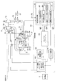
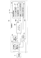
- FIG. 1 the whole structure of the control apparatus of the gas engine concerning this invention is demonstrated.
- a control device for a gas engine 3 having an exhaust turbocharger (hereinafter referred to as a supercharger) 1 will be described.
- the generator 5 is preferable as a driving target as shown in the drawing, the present invention is applicable to cases other than the generator.
- a gas engine (hereinafter referred to as an engine) 3 is a four-cycle gas engine, and shows a case of four cylinders including four cylinders 7.
- the supercharger 1 includes a turbine 1a driven by exhaust gas introduced from an exhaust port of a cylinder 7 through an exhaust passage 9, and an air compression compressor 1b coaxial with the turbine 1a.
- An exhaust outlet pipe 11 is connected.
- An air supply passage 13 that connects an air supply (air) outlet of the compressor 1 b and each cylinder 7 in the supercharger 1 branches in the middle and is connected to each cylinder 7.
- An air cooler 15 for cooling the air supplied from the outlet of the compressor 1b is provided in the air supply passage 13.
- a gas supply solenoid valve 17 for main chamber is provided for each cylinder 7 on the inlet side of each cylinder 7 in the supply passage 13, and fuel gas is supplied from a supply source (not shown) through a fuel supply main pipe 19. It has come to be.
- a fuel supply pipe 21 branched from the fuel supply main pipe 19 for each cylinder 7 and connected to each main chamber gas supply electromagnetic valve 17 has a fuel supply amount to the main combustion chamber 37 depending on its opening.
- a fuel flow rate adjustment valve 25 for adjustment is provided.
- a regulator (not shown) for regulating the fuel gas supplied to the cylinder 7 to a predetermined pressure is disposed on the fuel supply main pipe 19. Further, a fuel gas shut-off valve 27 in the fuel supply main pipe 19 is provided.
- a main combustion chamber 37 is formed between the upper surface of the piston 34 and the lower surface of the cylinder head 35, and inflow and discharge of the air-fuel mixture to the main combustion chamber 37 is performed in the cylinder head 35.
- An air supply valve 39 and an exhaust valve 41 for performing the above are provided.
- the cylinder head 35 is provided with a sub-combustion chamber 43 as an ignition device, and the nozzle hole 45 of the sub-combustion chamber 43 is disposed so as to be located at the center of the main combustion chamber 37.
- the sub-combustion chamber 43 is supplied with fuel gas via a sub-chamber gas supply electromagnetic valve 47, and further, in the sub-combustion chamber 43, the fuel gas supplied into the sub-combustion chamber 43 is ignited.
- a spark plug 51 having an ignition coil 49 attached thereto is attached.
- the turbine 1a of the supercharger 1 is provided with an exhaust bus pass valve 55 for adjusting the supercharging amount by bypassing the exhaust gas.
- the air cooler 15 is provided with a supply air temperature adjustment valve 57 that adjusts the cooling capacity by bypassing the cooling water.
- the spark ignition type gas engine using the spark plug 51 is shown as the ignition device.
- a fuel injection valve is provided in the auxiliary combustion chamber 43, and the fuel injection valve is provided inside the auxiliary combustion chamber.
- a liquid fuel such as light oil is injected into the formed air flow to ignite and burn the liquid fuel, and this ignition flame is introduced into the main combustion chamber 37 from the injection port 45 in a mixed gas of fuel gas and air. It is good also as what is called a subchamber pilot ignition system which burns this mixed gas by making it blow out.
- the exhaust gas from the engine 3 drives the turbine 1a of the supercharger 1 through the exhaust passage 9, and is discharged from the exhaust outlet pipe 11 to an exhaust purification device or the like.
- the supply air (air) pressurized by the coaxially driven compressor 1 b of the turbine 1 a is cooled and cooled by the air cooler 15, passes through the supply air passage 13, and the gas supply electromagnetic for the main chamber of each cylinder 7. It is introduced into the main combustion chamber 37 via the valve 17.
- the fuel from the fuel supply main pipe 19 is branched into the fuel supply pipe 21 of each cylinder 7 and introduced into the main chamber gas supply electromagnetic valve 17.
- the supply air and fuel are mixed to form a mixed gas and supplied to the main combustion chamber 37 of each cylinder 7 for combustion.
- the ignition plug 51 is ignited by the predetermined ignition timing signal from the ignition control means 53 to the fuel gas supplied into the auxiliary combustion chamber 43 via the auxiliary chamber gas supply electromagnetic valve 47 as described above. Then, the ignited flame is injected into the main combustion chamber 37 from the nozzle hole 45 of the sub-combustion chamber 43. As a result, the mixed gas flowing into the main combustion chamber 37 via the air supply valve 39 is combusted.
- the control device 33 determines the combustion state in the main combustion chamber 37 based on the signal from the in-cylinder pressure detector 59 that detects the in-cylinder pressure in the main combustion chamber 37 of each cylinder 7.
- Combustion diagnostic device 61 for diagnosing, gas supply controller 63 for controlling the supply and shutoff of fuel gas, and further the supply amount, ignition control means 53 for controlling ignition in the auxiliary combustion chamber 43, and combustion diagnosis for each cylinder 7
- An engine controller 65 that outputs an operation command to each cylinder 7 according to the result, that is, based on the diagnostic result signal M1 of misfire of each cylinder 7 or the diagnostic result signal M2 of abnormal combustion such as knocking other than misfire Configured.
- the combustion diagnostic apparatus 61 mainly includes a cycle detection unit 67, a misfire detection unit 69, an individual cylinder misfire determination unit 71, and a simultaneous misfire determination unit 73.
- the cycle detection means 67 detects a pulse signal indicating a crank angle period of one combustion cycle of the engine 3 composed of a plurality of cylinders based on a crank angle detection signal input from a crank angle detector 75 provided on the crankshaft or camshaft. To do. In the case of a 4-cycle engine, one combustion cycle is detected as a signal for every two rotations (720 degrees) of the crankshaft (see the pulse signal of one combustion cycle in FIG. 5).
- the minimum value of the misfire pressure ratio that has been confirmed and set that is, the allowable minimum pressure ratio Pn or less ( ⁇ P P / ⁇ P 0 ⁇ P n )
- Pn allowable minimum pressure ratio
- This misfire determination is performed on the basis of the in-cylinder pressure detection value for each cylinder 7 according to the firing order of multiple cylinders.
- the individual cylinder misfire determination means 71 causes a misfire in the cylinder 7 when the result of the misfire determination by the misfire detection means 69 reaches a predetermined number of times continuously in the same cylinder 7 to prevent erroneous determination. And outputs a diagnosis result signal M1 of misfire of the cylinder 7 to the engine controller 65.
- a control signal for stopping the supply of fuel gas or the like is individually output to the gas supply controller 63 for each cylinder 7.
- the simultaneous misfire determination means 73 counts the number of cylinders detected by the misfire detection means 69 within the period of one combustion cycle detected by the cycle detection means 67, and the total number of counts is a preset threshold cylinder. When the number has reached the number, it is determined that a plurality of cylinders are misfiring simultaneously, and an emergency stop signal M3 is output to the relay circuit 75.
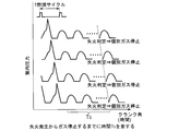
- FIG. 4 shows a determination image by the individual cylinder misfire determination means 71. It is the image figure which showed only the combustion stroke of the cylinder pressure waveform. Since it is necessary to detect misfire continuously from the occurrence of misfire in a specific cylinder to the misfire determination in that cylinder, it takes T 0 time to stop the fuel gas.
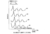
- FIG. 5 shows a determination image by the simultaneous misfire determination means 73. It is the image figure which showed only the combustion stroke of the cylinder pressure waveform.
- the number of misfiring cylinders in the period of the crank angle of one combustion cycle is counted, and it is determined that a plurality of cylinders are misfiring simultaneously when the total number is equal to or greater than a preset threshold number of cylinders.
- the simultaneous misfire of a plurality of cylinders is determined, and in the case of simultaneous misfire, all the cylinders are shut off and the engine is stopped. Therefore, the fuel gas stop is T 1 hour, and the engine stop state can be reached in a shorter time than the case of the individual cylinder misfire determination means 71 of FIG.
- the emergency stop signal M3 from the simultaneous misfire determination means 73 is output to the relay circuit 75, and an instruction signal is sent to the gas supply controller 63 without passing through the output to the engine controller 65 unlike the individual cylinder misfire determination means 71. Since it is output and further output to the fuel gas cutoff means 77, the fuel gas cutoff is performed quickly and reliably.
- the preset threshold number of cylinders in the simultaneous misfire determination means 73 is the minimum number of cylinders in which the fuel gas concentration in the exhaust passage 9 reaches the combustible region after a fixed number of cycles (after a fixed time) after determination of simultaneous misfire of a plurality of cylinders.
- the main combustion chamber 37 is opened by opening the air supply valve 39.
- the mixed gas of fuel gas and air introduced into the gas flows into the exhaust passage 9 as unburned gas without burning. For this reason, when a plurality of cylinders misfire simultaneously, the fuel gas concentration in the exhaust passage 9 increases in a short time and easily reaches the combustible region, and the risk of combustion in the exhaust passage 9 increases, If burned, there is a risk of causing damage to the exhaust passage 9 and surrounding damage.
- the fuel gas concentration in the exhaust passage 9 reaches the combustible region after a certain number of cycles (after a certain period of time) after the simultaneous misfire determination of the plurality of cylinders as the threshold cylinder number of the simultaneous misfire determination means 73 as described above.
- the minimum number of cylinders combustion of unburned fuel gas in the exhaust passage 9 can be prevented in the simultaneous misfire state.
- the “constant cycle” after the certain cycle means the number of combustion cycles corresponding to the time delay until the fuel gas is actually stopped after the simultaneous misfire is determined. That is, after it is determined that simultaneous misfire has occurred, a command is issued to the fuel gas shutoff means 77 of the gas supply controller 63, and the main chamber gas supply solenoid valves 17 provided in each cylinder 7 are all shut off to stop the engine. It means the time to reach a state.
- the minimum number of cylinders in which the fuel gas concentration in the exhaust passage 9 reaches the combustible range is determined in advance by the number of misfire cylinders and the exhaust passage 9 after the predetermined cycle (after a predetermined time). A relationship with the fuel gas concentration is obtained, and the minimum number of cylinders serving as a threshold is set based on the relationship. In the case of hydrocarbon fuel gas (methane, ethane, butane, propane, etc.), if the concentration is about 5-15%, self-ignition may occur depending on the exhaust temperature in the exhaust passage. Set as the minimum number of cylinders.
- the minimum number of cylinders that is 5% or more is set as 14 cylinders.
- the threshold cylinder number it may be set as 9 cylinders which is the number of cylinders in one bank.
- the gas supply solenoid valve 47 for the sub chamber only on one bank side or the spark plug Even when only 51 is in the non-operating state, the danger of combustion of the fuel gas in the exhaust passage 9 can be prevented by stopping the supply of the fuel gas and performing an emergency stop.
- the safe side may be adopted to set the threshold number of cylinders.
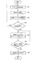
- step S1 and step S2 the crank angle detector 75 detects the crank angle
- the cylinder pressure detector 59 detects the cylinder pressure in the main combustion chamber 37 of each cylinder 7.
- step S3 a pulse signal of one combustion cycle is detected. That is, a pulse signal indicating the crank angle period (720 rpm) of one combustion cycle of the engine 3 composed of a plurality of cylinders based on a crank angle detection signal input from a crank angle detector 75 provided on the crankshaft or camshaft. Is detected.
- the misfire in the main combustion chamber 37 is detected by determining whether or not the minimum value of the misfire pressure ratio, that is, the allowable minimum pressure ratio Pn or less, is set. This misfire determination is performed on the basis of the in-cylinder pressure detection value for each cylinder 7 according to the firing order of multiple cylinders.
- step S1 If no misfire is detected, the process returns to step S1. If a misfire is detected, the process proceeds to step S5 to count the number of misfire cylinders in one combustion cycle. In step S6, it is determined whether the count number is equal to or greater than the threshold cylinder number. In the case of No, the process returns to step S5. In the case of Yes, it is determined that a plurality of cylinders are misfired simultaneously, and in step S7, an emergency stop signal M3 is output to the relay circuit 75. A cutoff signal is output to the fuel gas cutoff means 77 of the supply controller 63, and the main chamber gas supply solenoid valves 17 of all cylinders are shut off.
- the plurality of cylinders 7 are temporarily controlled to the simultaneous misfire state. It should be distinguished from controlled misfire. Therefore, as shown in FIG. 7, the output from the generator 5 is input to the relay circuit 75 or the simultaneous misfire determination means 73, and the output from the simultaneous misfire determination means 73 or the simultaneous misfire determination means 73. In the case of a misfire that is controlled according to the operating state of the generator 5 by limiting the determination itself, the fuel gas blocking means 77 of the gas supply controller 63 may not be operated. By controlling in this way, the reliability of the fuel gas cutoff control for preventing the combustion of the fuel gas in the exhaust passage targeted by the present invention is improved.
- simultaneous misfire occurs when misfire is determined in a cylinder equal to or greater than the threshold number of cylinders within the crank angle period of one combustion cycle of the engine 3 including the plurality of cylinders 7.
- simultaneous misfire can be accurately determined, and supply of fuel gas to all cylinders can be stopped to perform an emergency stop.
- a gas engine configured to mix fuel gas and air and combust in the combustion chamber of the engine, it is possible to accurately determine simultaneous misfires of a plurality of cylinders occurring in one cycle, and The gas supply can be stopped to minimize the inflow of unburned fuel gas into the exhaust system and prevent combustion in the exhaust passage, so it can be used for generator gas engines and other gas engines. Suitable for use.
Landscapes
- Engineering & Computer Science (AREA)
- Chemical & Material Sciences (AREA)
- Combustion & Propulsion (AREA)
- Mechanical Engineering (AREA)
- General Engineering & Computer Science (AREA)
- Biomedical Technology (AREA)
- Health & Medical Sciences (AREA)
- Chemical Kinetics & Catalysis (AREA)
- General Chemical & Material Sciences (AREA)
- Oil, Petroleum & Natural Gas (AREA)
- Combined Controls Of Internal Combustion Engines (AREA)
- Output Control And Ontrol Of Special Type Engine (AREA)
- Electrical Control Of Air Or Fuel Supplied To Internal-Combustion Engine (AREA)
Abstract
クランク角検出器(75)から入力されるクランク角検出値に基づき複数シリンダからなるエンジンの1燃焼サイクルのクランク角期間を検出するサイクル検出手段(67)と、筒内圧力検出器(59)から入力される筒内圧力検出値に基づき主燃焼室(37)内の失火を検出する失火検出手段(69)と、失火検出手段(69)によって失火を検出したシリンダの前記1燃焼サイクル内の総数が予め設定された閾値シリンダ数以上のときに複数シリンダが同時失火であると判定する同時失火判定手段(73)と、該同時失火判定手段(73)によって1燃焼サイクル中に複数シリンダが同時失火と判定したとき全シリンダへの燃料ガスを遮断することを特徴とする。
Description
本発明は、給気通路を介して供給される空気と燃料供給通路から供給される燃料ガスを混合して燃焼室内に供給し、着火燃焼せしめるガスエンジンにおいて、シリンダが失火した場合に未燃ガスが排気系統に流入し、煙道で燃焼するのを防止するガスエンジンの制御装置および方法に関する。
一般的な中速ガスエンジンにおいては、給気通路を介して供給される空気(給気)と、燃料供給通路から供給される燃料ガスを混合してエンジンの主燃焼室に供給して燃焼運転を行い、駆動力を得る構成となっている。また、シリンダヘッドに主燃焼室へ連通する副燃焼室を設け、燃料噴射弁から副室の内部に形成された空気流中に軽油等の液体燃料を噴射して該液体燃料を着火燃焼せしめ、この着火火炎を副室噴口から、給気弁の開弁によって主燃焼室内に導入された燃料ガスと空気との混合ガス中に噴出せしめることにより該混合ガスを燃焼せしめる副室パイロット着火式ガスエンジンについて知られている。
また、シリンダヘッドに設けられた副燃焼室に着火用の燃料ガスを供給して、着火性のよい混合気を作り、スパークプラグで点火して燃焼せしめて、この着火火炎を副室噴口から、給気弁の開弁によって主燃焼室内に導入された燃料ガスと空気との混合ガス中に噴出せしめることにより該混合ガスを燃焼せしめる火花着火方式ガスエンジンについても知られている。
このようなガスエンジンでは、所望のエンジン出力が得られるように、燃焼室に供給される燃料流量、空気流量が適正に制御されるとともに、ノッキングや失火を回避した安定運転が可能な空燃比に制御される。しかし、燃料供給系や着火系の部品の損耗や故障等の不具合が生じると異常燃焼(ノッキング)や失火を生じやすい。
例えば、給気通路に燃料供給通路から燃料ガスを供給する燃料流量制御弁の故障により所望の燃料ガスが供給されていない場合や、副燃焼室へ軽油等の液体燃料を供給する制御弁やスパークプラグの故障等のように着火装置の不具合の場合には全気筒、または特定の気筒において失火が生じる。
例えば、給気通路に燃料供給通路から燃料ガスを供給する燃料流量制御弁の故障により所望の燃料ガスが供給されていない場合や、副燃焼室へ軽油等の液体燃料を供給する制御弁やスパークプラグの故障等のように着火装置の不具合の場合には全気筒、または特定の気筒において失火が生じる。
ガスエンジンの失火を検出してエンジンを強制停止する技術の一例として、特開2001-12292号公報(特許文献1)、および特開2007-170405号公報(特許文献2)が提案されている。
この特許文献1の要約、段落0063~0067等には、複数の気筒からなるエンジンの排圧波形を気筒毎に判別して検出し、各気筒の所定のクランク角範囲での排圧波形の面積を算出して、これと直前の所定サイクルの移動平均値と比較しこの波形面積の平均値に対する比率を、基準値と比較して失火を判定する。そして、失火を判定したときにはエンジンを強制停止することが開示されている。
この特許文献1の要約、段落0063~0067等には、複数の気筒からなるエンジンの排圧波形を気筒毎に判別して検出し、各気筒の所定のクランク角範囲での排圧波形の面積を算出して、これと直前の所定サイクルの移動平均値と比較しこの波形面積の平均値に対する比率を、基準値と比較して失火を判定する。そして、失火を判定したときにはエンジンを強制停止することが開示されている。
また、特許文献2の段落0031~0032等には、筒内圧力検出器から入力される筒内圧力検出値及びクランク角検出器から入力されるクランク角検出値に基づき、吸気圧力を含む圧縮始め以前の基準圧力Pbとの差圧ΔP(ΔP=P-Pb)をクランク角に対応させて算出し、筒内最高圧力Ppと前記基準圧力との差圧ΔPpと、圧縮行程における一又は複数の任意点の差圧ΔP0との比である筒内最高圧力比(ΔPp/ΔP0)が、設定された失火の許容最小圧力比Pn以下になった時に燃焼室内における失火発生の判定を行うことが示され、さらに、許容継続サイクル数になったときに当該失火発生シリンダの燃料噴射を遮断することが示されている。
ガスエンジンにおいては、前述のように給気通路に燃料供給通路から燃料ガスを供給する燃料流量制御弁の故障により所望の燃料ガスが供給されていない場合や、副燃焼室へ軽油等の液体燃料を供給する制御弁やスパークプラグの故障等の着火装置の不具合の場合に全シリンダまたは特定シリンダにおいて失火が生じる。
特に、副燃焼室へ軽油等の液体燃料を供給する制御弁やスパークプラグの故障等のように着火装置の不具合の場合においては、給気弁の開弁によって主燃焼室内に導入された燃料ガスと空気との混合ガスが、燃焼せずに未燃ガスとして排気系統に流入する。
そのため、複数シリンダが同時に失火した場合には、短時間に排気通路において燃料ガス濃度が高まり可燃域に達しやすく、排気通路内での燃焼の危険性が増す。そして、排気通路内燃焼が生じた場合にはエンジンやプラント設備の損傷や周囲への甚大な被害を引き起こすおそれがある。
特に、副燃焼室へ軽油等の液体燃料を供給する制御弁やスパークプラグの故障等のように着火装置の不具合の場合においては、給気弁の開弁によって主燃焼室内に導入された燃料ガスと空気との混合ガスが、燃焼せずに未燃ガスとして排気系統に流入する。
そのため、複数シリンダが同時に失火した場合には、短時間に排気通路において燃料ガス濃度が高まり可燃域に達しやすく、排気通路内での燃焼の危険性が増す。そして、排気通路内燃焼が生じた場合にはエンジンやプラント設備の損傷や周囲への甚大な被害を引き起こすおそれがある。
前述の特許文献1の失火判定は、排圧波形の面積を基に判定するものであるが、特定の単一シリンダでの失火判定であり複数シリンダが同時失火状態であることを判定することまでは開示していない。また、直前の所定サイクルの移動平均値と比較しているため、直前の所定サイクルのデータが必要であり、判定結果を出力するまでに複数サイクルの経過時間が必要になりエンジン停止までに時間を要するため、複数シリンダが同時に失火した場合のように短時間で失火判定をしてエンジン停止が必要とされる判定方法としては適さないものである。
また、特許文献2の失火判定は、筒内圧力の筒内最高圧力比(ΔPp/ΔP0)を基に失火を判定しているが、前記特許文献1と同様に特定の単一シリンダでの失火判定であり複数シリンダが同時失火状態であることを判定することまでは開示していない。また、誤判定の防止のために失火が数サイクル連続した場合に、当該失火発生シリンダの燃料噴射を遮断せしめるためエンジン停止までに時間を要し、複数シリンダが同時に失火した場合のような短時間での同時失火の判定と危急停止を行う判定方法としては適さないものである。
そこで、本発明はこのような課題に鑑みてなされたものであり、ガスエンジンにおいて、1サイクル中に発生する複数シリンダの同時失火を正確に判定して、燃料ガスの供給を停止して、未燃の燃料ガスの排気系統への流入を最小限に抑えて排気通路内での燃焼を防止することを目的とする。
前記目的を達成するため、ガスエンジンの制御装置にかかる発明は、燃料ガスと空気とを混合しエンジンの燃焼室内にて燃焼せしめるように構成されたガスエンジンの制御装置において、前記燃焼室内における筒内圧力を検出する筒内圧力検出器と、前記エンジンのクランク角度を検出するクランク角検出器と、を設け、前記クランク角検出器から入力されるクランク角検出値に基づき複数シリンダからなるエンジンの1燃焼サイクルのクランク角期間を検出するサイクル検出手段と、前記筒内圧力検出器から入力される筒内圧力検出値に基づき、燃焼室内における失火を検出する失火検出手段と、前記失火検出手段によって失火を検出したシリンダの前記1燃焼サイクル内の総数が予め設定された閾値シリンダ数以上のときに複数シリンダが同時失火であると判定する同時失火判定手段と、該同時失火判定手段によって1燃焼サイクル中に複数シリンダが同時に失火していると判定したとき全てのシリンダへの燃料ガスの供給を遮断する燃料ガス遮断手段と、を備えたことを特徴とする。
かかる発明によれば、複数シリンダからなるガスエンジンの1燃焼サイクルのクランク角期間内に閾値シリンダ数以上のシリンダで失火を検出した場合に、複数シリンダの同時失火が発生していると判定することで、同時失火を正確に判定でき、全シリンダへの燃料ガスの供給を停止する危急停止を行うことができる。
その結果、未燃の燃料ガスが排気通路に集中的に流入して、短時間に排気通路において燃料ガス濃度が高まり可燃域することを防止でき、排気通路内での燃焼の危険性を防止できる。
その結果、未燃の燃料ガスが排気通路に集中的に流入して、短時間に排気通路において燃料ガス濃度が高まり可燃域することを防止でき、排気通路内での燃焼の危険性を防止できる。
また、本装置発明において好ましくは、前記同時失火判定手段の閾値シリンダ数は複数シリンダの同時失火を判定した後の一定サイクル後に排気通路内の燃料ガス濃度が可燃域に達する最小シリンダ数であるとよい。
このように閾値シリンダ数を設定することによって、複数シリンダの同時失火状態において排気通路内での未燃燃料ガスの燃焼が確実に防止される。
なお、「一定サイクル後」の一定サイクルとは、同時失火を判定し、その判定後に実際に燃料ガスが遮断されるまでの時間遅れに相当する燃焼サイクル数を意味している。つまり、同時失火が発生したと判定してから、ガス供給コントローラ(燃料ガス遮断手段)に指令を発し各シリンダに設けられているガス供給電磁弁が全て遮断してエンジン停止状態になるまでの時間を意味する。
なお、「一定サイクル後」の一定サイクルとは、同時失火を判定し、その判定後に実際に燃料ガスが遮断されるまでの時間遅れに相当する燃焼サイクル数を意味している。つまり、同時失火が発生したと判定してから、ガス供給コントローラ(燃料ガス遮断手段)に指令を発し各シリンダに設けられているガス供給電磁弁が全て遮断してエンジン停止状態になるまでの時間を意味する。
また、排気通路内の燃料ガス濃度が可燃域に達する最小シリンダ数とは、図6に示すように、予め試験によって、失火シリンダ数と前記一定サイクル後の排気通路内の燃料ガス濃度との関係を求めておき、その関係を基に閾値となる最小シリンダ数を設定する。炭化水素系の燃料ガス(メタン、エタン、ブタン、プロパン等)の場合には、濃度が略5~15%になると可燃領域になり排気通路内で排気温度によって自己着火を生じるおそれがあるため、5%以上にならないような最小シリンダ数として設定するとよい。
また、本装置発明において好ましくは、前記エンジンがV型エンジンの場合は、前記同時失火判定手段の閾値シリンダ数は片バンクのシリンダ数であるとよい。
このように閾値シリンダ数を設定することによって、例えば電気配線の断線や、電気コネクターの接続不良等のトラブルによって片バンク側だけのガス供給電磁弁のみが非作動状態の場合には、排気通路内の燃料ガス濃度が可燃域に達する場合が多いため、このような場合においても、燃料ガスの供給を停止して危急停止を行うことで、排気通路内での燃料ガスの燃焼の危険性を防止できる。
このように閾値シリンダ数を設定することによって、例えば電気配線の断線や、電気コネクターの接続不良等のトラブルによって片バンク側だけのガス供給電磁弁のみが非作動状態の場合には、排気通路内の燃料ガス濃度が可燃域に達する場合が多いため、このような場合においても、燃料ガスの供給を停止して危急停止を行うことで、排気通路内での燃料ガスの燃焼の危険性を防止できる。
また、本装置発明において好ましくは、前記ガスエンジンが発電機を駆動するエンジンであり、発電機が所定の運転領域の運転状態の場合には前記同時失火判定手段の判定結果を採用しないようにする。
このように構成することで、発電機の運転状態によっては、つまり無負荷運転領域や低負荷運転領域や負荷遮断時には、一時的に複数シリンダを同時失火状態に制御するため、発電機の運転状態に応じて制御される失火と区別できる。これによって、本発明の複数シリンダの同時失火時の制御の信頼性が向上する。
また、ガスエンジンの制御方法にかかる発明は、燃料ガスと空気とを混合しエンジンの燃焼室内にて燃焼せしめるように構成されたガスエンジンの制御方法において、クランク角検出器から入力されるクランク角検出値に基づき複数シリンダからなるエンジンの1燃焼サイクルのクランク角期間を検出するステップと、筒内圧力検出器から入力される筒内圧力検出値に基づき、燃焼室内における失火を検出するステップと、前記1燃焼サイクルにおいて失火を検出したシリンダ数をカウントするステップと、カウントの総数が予め設定された閾値シリンダ数以上のときに複数シリンダが同時失火していると判定するステップと、1燃焼サイクル中に複数シリンダが同時に失火していると判定したとき全てのシリンダへの燃料ガスの供給を遮断するステップと、を備えたことを特徴とする。
かかる発明によれば、複数シリンダからなるガスエンジンの1燃焼サイクルのクランク角期間内に失火したシリンダ数をカウントして総数が閾値シリンダ数以上の場合には、複数シリンダが同時失火していると判定することで、同時失火を正確に判定でき、全シリンダへの燃料ガスの供給を停止して危急停止を行うことができる。
その結果、未燃ガスが排気通路に集中的に流入して、短時間に排気通路において燃料ガス濃度が高まり可燃域することを防止でき、排気通路内での燃焼の危険性を防止できる。
その結果、未燃ガスが排気通路に集中的に流入して、短時間に排気通路において燃料ガス濃度が高まり可燃域することを防止でき、排気通路内での燃焼の危険性を防止できる。
また、本方法発明において好ましくは、前記同時失火の判定における閾値シリンダ数は複数シリンダの同時失火を判定した後の一定サイクル後に排気通路内の燃料ガス濃度が可燃域に達する最小シリンダ数であるとよい。
このように閾値シリンダ数を設定することによって、複数シリンダの同時失火状態において排気通路内での未燃燃料ガスの燃焼が確実に防止される。
このように閾値シリンダ数を設定することによって、複数シリンダの同時失火状態において排気通路内での未燃燃料ガスの燃焼が確実に防止される。
また、本方法発明において好ましくは、前記1燃焼サイクルにおける各シリンダの失火検出は着火順序毎に筒内圧力検出器から入力される筒内圧力検出値に基づき行うと共に、複数シリンダの同時失火の判定は1燃焼サイクル毎に判定するとよい。
このように、1燃焼サイクル毎に複数シリンダの同時失火が判定されて、その結果によってエンジンの危急停止がなされるため、短時間に判定されて排気通路内での未燃燃料ガスの燃焼を迅速に防止できる。
このように、1燃焼サイクル毎に複数シリンダの同時失火が判定されて、その結果によってエンジンの危急停止がなされるため、短時間に判定されて排気通路内での未燃燃料ガスの燃焼を迅速に防止できる。
本装置発明および方法発明によれば、燃料ガスと空気とを混合しエンジンの燃焼室内にて燃焼せしめるように構成されたガスエンジンにおいて、1サイクル中に発生する複数シリンダの同時失火を正確に判定して、燃料ガスの供給を停止して、未燃の燃料ガスの排気系統への流入を最小限に抑えて排気通路内燃焼を防止することができる。
以下、本発明を図に示した実施形態を用いて詳細に説明する。
但し、この実施形態に記載されている構成部品の寸法、材質、形状、その相対配置などは特に特定的な記載がない限り、この発明の範囲をそれのみに限定する趣旨ではなく、単なる説明例にすぎない。
但し、この実施形態に記載されている構成部品の寸法、材質、形状、その相対配置などは特に特定的な記載がない限り、この発明の範囲をそれのみに限定する趣旨ではなく、単なる説明例にすぎない。
図1を参照して、本発明にかかるガスエンジンの制御装置の全体構成について説明する。
本実施形態では、一例として排気ターボ過給機(以下過給機という)1を備えたガスエンジン3の制御装置について説明するが、過給機1を備えないガスエンジンにも適用可能であり、また、駆動対象は図示するように発電機5が好ましいが、発電機以外の場合にも適用可能である。
本実施形態では、一例として排気ターボ過給機(以下過給機という)1を備えたガスエンジン3の制御装置について説明するが、過給機1を備えないガスエンジンにも適用可能であり、また、駆動対象は図示するように発電機5が好ましいが、発電機以外の場合にも適用可能である。
ガスエンジン(以下エンジンという)3は4サイクルのガスエンジンからなり、4つのシリンダ7を備えた4シリンダの場合を示す。
過給機1はシリンダ7の排気ポートから排気通路9を通って導入される排ガスによって駆動されるタービン1a及び該タービン1aと同軸の空気圧縮用のコンプレッサ1bよりなり、タービン1aの排気出口には排気出口管11が接続されている。
前記過給機1におけるコンプレッサ1bの給気(空気)出口と各シリンダ7とを接続する給気通路13は途中で分岐して各シリンダ7に接続されている。該給気通路13の途中には、コンプレッサ1bの出口からの給気を冷却する空気冷却器15が設けられている。
過給機1はシリンダ7の排気ポートから排気通路9を通って導入される排ガスによって駆動されるタービン1a及び該タービン1aと同軸の空気圧縮用のコンプレッサ1bよりなり、タービン1aの排気出口には排気出口管11が接続されている。
前記過給機1におけるコンプレッサ1bの給気(空気)出口と各シリンダ7とを接続する給気通路13は途中で分岐して各シリンダ7に接続されている。該給気通路13の途中には、コンプレッサ1bの出口からの給気を冷却する空気冷却器15が設けられている。
また、給気通路13の各シリンダ7の入口側にはシリンダ7毎に主室用ガス供給電磁弁17が配設され、燃料ガスが、その供給源(図示省略)から燃料供給主管19によって供給されるようになっている。そして、該燃料供給主管19からシリンダ7毎に分岐して前記各主室用ガス供給電磁弁17に接続される燃料供給管21には、その開度により主燃焼室37への燃料供給量を調整する燃料流量調整弁25が設けられている。
また、前記燃料供給主管19上には、シリンダ7へ供給される燃料ガスを所定の圧力に調圧するレギュレータ(図示略)が配設されている。さらに、前記燃料供給主管19における燃料ガスの遮断弁27が設置されている。
また、前記燃料供給主管19上には、シリンダ7へ供給される燃料ガスを所定の圧力に調圧するレギュレータ(図示略)が配設されている。さらに、前記燃料供給主管19における燃料ガスの遮断弁27が設置されている。
燃料ガス流量、給気流量等の演算および制御は制御装置33で行われており、発電機5の出力(回転数、負荷)に応じて燃料流量調整弁25が調整されるようになっている。
さらに、図2示すように、ピストン34の上面とシリンダヘッド35の下面との間には主燃焼室37が形成されるとともに、シリンダヘッド35には主燃焼室37への混合気の流入および排出を行う給気弁39および排気弁41が設けられている。
また、シリンダヘッド35には着火装置としての副燃焼室43が設けられ、副燃焼室43の噴口45は主燃焼室37の中央部に位置するように配置されている。この副燃焼室43には、副室用ガス供給電磁弁47を介して燃料ガスが供給され、さらに、副燃焼室43内には、副燃焼室43内に供給された燃料ガスを着火するために点火コイル49が装着された点火プラグ51が取り付けられている。
また、シリンダヘッド35には着火装置としての副燃焼室43が設けられ、副燃焼室43の噴口45は主燃焼室37の中央部に位置するように配置されている。この副燃焼室43には、副室用ガス供給電磁弁47を介して燃料ガスが供給され、さらに、副燃焼室43内には、副燃焼室43内に供給された燃料ガスを着火するために点火コイル49が装着された点火プラグ51が取り付けられている。
副燃焼室43内に供給された燃料ガスに点火プラグ51に着火制御手段53からの点火信号によって点火すると、副燃焼室43内の燃料ガスが着火して、着火火炎が副燃焼室43の噴口45から主燃焼室37内に噴射して、主燃焼室37内に給気弁39から流入した燃料ガスと空気との混合ガスを燃焼させる。これによって、希薄な混合ガスに対しても確実に着火して燃焼させることができる。
また、図2に示すように、過給機1のタービン1aには排気をバイパスして過給量を調整する排気バスパス弁55が設けられている。さらに、空気冷却器15には、冷却水をバイパスして冷却能力を調整する給気温度調整弁57が設けられている。
なお、本実施形態においては着火装置として、点火プラグ51を用いる火花着火方式のガスエンジンについて示したが、副燃焼室43に燃料噴射弁を設けて、該燃料噴射弁から副燃焼室の内部に形成された空気流中に軽油等の液体燃料を噴射して該液体燃料を着火燃焼せしめ、この着火火炎を噴口45から、主燃焼室37内に導入された燃料ガスと空気との混合ガス中に噴出せしめることにより該混合ガスを燃焼せしめる、所謂副室パイロット着火方式としてもよい。
以上の構成からなるエンジン3において、エンジン3からの排ガスは排気通路9を経て過給機1のタービン1aを駆動し、排気出口管11から排気浄化装置等に排出される。該タービン1aの同軸駆動されるコンプレッサ1bにより加圧された給気(空気)は、前記空気冷却器15にて冷却、降温され給気通路13を通って各シリンダ7の主室用ガス供給電磁弁17を介して主燃焼室37に導入される。また、燃料供給主管19からの燃料は各シリンダ7の燃料供給管21に分岐されて前記主室用ガス供給電磁弁17へ導入される。そして該主室用ガス供給電磁弁17において前記給気と燃料とが混合せしめられて混合ガスとなって各シリンダ7の主燃焼室37に供給され、燃焼に供される。
一方、前述のように副室用ガス供給電磁弁47を介して副燃焼室43内に供給された燃料ガスに対して、着火制御手段53からの所定の点火タイミングの信号によって点火プラグ51が点火して着火され、この着火した火炎が副燃焼室43の噴口45から主燃焼室37内に噴射する。これによって、主燃焼室37内に給気弁39を介して流入した混合ガスが燃焼される。
次に、制御装置33について、主に図1、2を参照して説明する。
制御装置33は、図2に示すように、各シリンダ7の主燃焼室37内の筒内圧力を検出する筒内圧力検出器59からの信号を基に、主燃焼室37内における燃焼状態を診断する燃焼診断装置61と、燃料ガスの供給および遮断、さらには供給量を制御するガス供給コントローラ63と、副燃焼室43内の着火を制御する着火制御手段53と、各シリンダ7の燃焼診断結果に応じて、すなわち各シリンダ7の失火の診断結果信号M1や失火以外のノッキング等の異常燃焼の診断結果信号M2に基づいて各シリンダ7に対する運転指令を出力するエンジンコントローラ65と、を有して構成されている。
制御装置33は、図2に示すように、各シリンダ7の主燃焼室37内の筒内圧力を検出する筒内圧力検出器59からの信号を基に、主燃焼室37内における燃焼状態を診断する燃焼診断装置61と、燃料ガスの供給および遮断、さらには供給量を制御するガス供給コントローラ63と、副燃焼室43内の着火を制御する着火制御手段53と、各シリンダ7の燃焼診断結果に応じて、すなわち各シリンダ7の失火の診断結果信号M1や失火以外のノッキング等の異常燃焼の診断結果信号M2に基づいて各シリンダ7に対する運転指令を出力するエンジンコントローラ65と、を有して構成されている。
この燃焼診断装置61は、サイクル検出手段67と、失火検出手段69と、個別シリンダ失火判定手段71と、同時失火判定手段73とを主に備えている。
サイクル検出手段67は、クランク軸またはカム軸に設けられたクランク角検出器75から入力されるクランク角検出信号に基づき複数シリンダからなるエンジン3の1燃焼サイクルのクランク角期間を示すパルス信号を検出する。4サイクルエンジンの場合には1燃焼サイクルがクランク軸の2回転(720度)ごとの信号として検出されるようになっている(図5の1燃焼サイクルのパルス信号参照)。
サイクル検出手段67は、クランク軸またはカム軸に設けられたクランク角検出器75から入力されるクランク角検出信号に基づき複数シリンダからなるエンジン3の1燃焼サイクルのクランク角期間を示すパルス信号を検出する。4サイクルエンジンの場合には1燃焼サイクルがクランク軸の2回転(720度)ごとの信号として検出されるようになっている(図5の1燃焼サイクルのパルス信号参照)。
失火検出手段69は、筒内圧力検出器59から入力される筒内圧力検出値とクランク角検出器75から入力されるクランク角検出値とに基づいて、エンジン運転中において大気状態等の外部条件による変動が小さい給気圧力を含む圧縮始め以前の基準圧力Pbと筒内圧力の検出値Pを検出する。そして、基準圧力Pbと筒内圧力の検出値Pとを基に、その差圧ΔP(ΔP=P-Pb)をベースとした筒内圧力比ΔP/ΔP0を算出し、該筒内圧力比ΔP/ΔP0用いて失火状態にあるか否かを判定して、失火を検出する。
ここで、差圧ΔP0は、圧縮行程における特定のクランク角における筒内圧力P0と基準圧力Pbとの差圧ΔP0(ΔP0=P0-Pb)である。
ここで、差圧ΔP0は、圧縮行程における特定のクランク角における筒内圧力P0と基準圧力Pbとの差圧ΔP0(ΔP0=P0-Pb)である。
具体的には、特定のタイミングでの圧力PPと基準圧力Pbとの差圧ΔPP(ΔPP=PP-Pb)を用いて圧力比ΔPP/ΔP0が、予め試験等で確認して設定された失火の圧力比の最小値すなわち許容最小圧力比Pn以下(ΔPP/ΔP0≦Pn)になったとき、主燃焼室37内に失火が発生していると判定する。この失火判定は多気筒を着火順に従ってシリンダ7毎、筒内圧力検出値を基に行う。
なお、圧力比ΔPP/ΔP0を用いる手法は一例であり、単に筒内圧力差ΔPP(ΔPP=PP-Pb)を用いて判定してもよい。
なお、圧力比ΔPP/ΔP0を用いる手法は一例であり、単に筒内圧力差ΔPP(ΔPP=PP-Pb)を用いて判定してもよい。
個別シリンダ失火判定手段71は、前記失火検出手段69による失火判定の結果が、誤判定防止のため同一シリンダ7で連続して所定回数に達した場合に、当該シリンダ7において失火が発生していると判定し、エンジンコントローラ65へ当該シリンダ7の失火の診断結果信号M1を出力する。そして、シリンダ7毎に個別にガス供給コントローラ63へ燃料ガスの供給停止等の制御信号を出力するようになっている。
同時失火判定手段73は、前記失火検出手段69によって失火を検出したシリンダ数を、前記サイクル検出手段67によって検出される1燃焼サイクルの期間内カウントし、そのカウント総数が、予め設定された閾値シリンダ数以上に達している場合には、複数シリンダが同時失火を起こしていると判定し、危急停止信号M3をリレー回路75へ出力する。
図4に、前記個別シリンダ失火判定手段71による判定イメージを示す。筒内圧力波形の燃焼行程のみを示したイメージ図である。特定シリンダの失火発生からそのシリンダにおける失火判定までに失火を連続して検出する必要があるため燃料ガス停止までT0時間を要する。
図5に、前記同時失火判定手段73による判定イメージを示す。筒内圧力波形の燃焼行程のみを示したイメージ図である。1燃焼サイクルのクランク角の期間内における失火シリンダ数をカウントしてその総数が、予め設定された閾値シリンダ数以上のときに複数シリンダが同時失火であると判定する。
複数シリンダの同時失火を判定して、同時失火の場合には全シリンダを遮断してエンジン停止させる。このため燃料ガス停止までT1時間であり、図4の個別シリンダ失火判定手段71による場合よりも短時間でエンジン停止状態に達することができる。
複数シリンダの同時失火を判定して、同時失火の場合には全シリンダを遮断してエンジン停止させる。このため燃料ガス停止までT1時間であり、図4の個別シリンダ失火判定手段71による場合よりも短時間でエンジン停止状態に達することができる。
また、同時失火判定手段73からの危急停止信号M3はリレー回路75へ出力されており、個別シリンダ失火判定手段71のようにエンジンコントローラ65への出力を介さずにガス供給コントローラ63に指示信号が出力され、さらに燃料ガス遮断手段77へ出力されるため、燃料ガス遮断が迅速かつ確実に行われる。
同時失火判定手段73における予め設定された閾値シリンダ数は、複数シリンダの同時失火の判定後の一定サイクル数後(一定時間後)に排気通路9内の燃料ガス濃度が可燃域に達する最小シリンダ数に設定される。
副燃焼室43への燃料ガスを供給する副室用ガス供給電磁弁47や点火プラグ51の故障等のように着火装置の不具合の場合においては、給気弁39の開弁によって主燃焼室37内に導入された燃料ガスと空気との混合ガスが、燃焼せずに未燃ガスとして排気通路9に流入する。このため、複数シリンダが同時に失火した場合には、短時間で排気通路9において燃料ガス濃度が高まり可燃域に達しやすく、排気通路9内での燃焼の危険性が増大し、排気通路9内で燃焼した場合には排気通路9の損傷や周囲への被害を引き起こすおそれがある。
このため、前記同時失火判定手段73の閾値シリンダ数を前述のように複数シリンダの同時失火の判定後の一定サイクル数後(一定時間後)に排気通路9内の燃料ガス濃度が可燃域に達する最小シリンダ数に設定することによって、同時失火状態において排気通路9内での未燃燃料ガスの燃焼を防止できる。
なお、前記一定サイクル後の「一定サイクル」とは、同時失火の判定後に実際に燃料ガスが停止されるまでの時間遅れ分に相当する燃焼サイクル数を意味する。つまり、同時失火が発生したと判定してから、ガス供給コントローラ63の燃料ガス遮断手段77に指令を発し各シリンダ7に設けられている主室用ガス供給電磁弁17が全て遮断してエンジン停止状態になるまでの時間を意味する。
また、排気通路9内の燃料ガス濃度が可燃域に達する最小シリンダ数は、図6に示すように、予め試験によって、失火シリンダ数と前記一定サイクル後(一定時間後)の排気通路9内の燃料ガス濃度との関係を求めておき、その関係を基に閾値となる最小シリンダ数を設定する。炭化水素系の燃料ガス(メタン、エタン、ブタン、プロパン等)の場合には、濃度が略5~15%になると排気通路内で排気温度によって自己着火を生じるおそれがあるため、5%以上にならないような最小シリンダ数として設定する。
図6の場合にはV型18シリンダのガスエンジンの場合を示しており、5%以上になる最小シリンダ数として14シリンダとして設定する。
また、前記閾値シリンダ数の設定の他の例として片バンクのシリンダ数である9シリンダとして設定してもよい。
また、前記閾値シリンダ数の設定の他の例として片バンクのシリンダ数である9シリンダとして設定してもよい。
このように閾値シリンダ数を片バンクのシリンダ数に設定することによって、例えば電気配線の断線や、電気コネクターの接続不良等のトラブルによって片バンク側だけの副室用ガス供給電磁弁47や点火プラグ51のみが非作動状態の場合においても、燃料ガスの供給を停止して危急停止を行うことで、排気通路9内での燃料ガスの燃焼の危険性を防止できる。
なお、片バンク数が図6の排気通路内燃料ガス濃度を基に設定した最小シリンダ数より大きい時には、安全サイドを採用して閾値シリンダ数とするとよい。
なお、片バンク数が図6の排気通路内燃料ガス濃度を基に設定した最小シリンダ数より大きい時には、安全サイドを採用して閾値シリンダ数とするとよい。
制御装置33の制御手順を図3のフローチャートを参照して次に説明する。
まず、ステップS1、ステップS2では、クランク角検出器75によってクランク角度の検出、および筒内圧力検出器59によって各シリンダ7の主燃焼室37内の筒内圧力を検出する。ステップS3で、1燃焼サイクルのパルス信号を検出する。すなわち、クランク軸またはカム軸に設けられたクランク角検出器75から入力されるクランク角検出信号に基づき複数シリンダからなるエンジン3の1燃焼サイクルのクランク角期間(2回転720度)を示すパルス信号を検出する。
まず、ステップS1、ステップS2では、クランク角検出器75によってクランク角度の検出、および筒内圧力検出器59によって各シリンダ7の主燃焼室37内の筒内圧力を検出する。ステップS3で、1燃焼サイクルのパルス信号を検出する。すなわち、クランク軸またはカム軸に設けられたクランク角検出器75から入力されるクランク角検出信号に基づき複数シリンダからなるエンジン3の1燃焼サイクルのクランク角期間(2回転720度)を示すパルス信号を検出する。
ステップS4で、特定タイミングでの圧力PPと基準圧力Pbとの差圧ΔPP(ΔPP=PP-Pb)を用いて圧力比ΔPP/ΔP0が、予め試験等で確認して設定された失火の圧力比の最小値すなわち許容最小圧力比Pn以下になったか否かを判定して主燃焼室37内での失火を検出する。この失火判定は多気筒を着火順に従ってシリンダ7毎、筒内圧力検出値を基に行う。
失火を検出しない場合にはステップS1に戻り、失火を検出した場合にはステップS5に進んで、1燃焼サイクルなにおける失火シリンダ数をカウントする。そして、ステップS6では、そのカウント数が閾値シリンダ数以上か否かが判定される。Noの場合にはステップS5に戻り、Yesの場合には複数シリンダが同時失火していると判定して、ステップS7で危急停止信号M3をリレー回路75に出力して、リレー回路75から、ガス供給コントローラ63の燃料ガス遮断手段77に遮断信号が出力されて全シリンダの主室用ガス供給電磁弁17が遮断される。
なお、発電機5の運転状態によっては、つまり無負荷運転領域や低負荷運転領域や負荷遮断時には、一時的に複数シリンダ7を同時失火状態に制御するため、発電機5の運転状態に応じて制御される失火と区別する必要がある。このため、図7に示すように発電機5からの出力をリレー回路75に、または同時失火判定手段73に入力して、同時失火判定手段73からの出力に対し、または同時失火判定手段73の判定自体に制限を掛けて、発電機5の運転状態に応じて制御される失火の場合には、ガス供給コントローラ63の燃料ガス遮断手段77を作動させないようにするとよい。
このように制御することで、本発明が目的とする排気通路内での燃料ガスの燃焼防止のための燃料ガス遮断制御の信頼性が向上する。
このように制御することで、本発明が目的とする排気通路内での燃料ガスの燃焼防止のための燃料ガス遮断制御の信頼性が向上する。
以上のように本実施形態によると、複数のシリンダ7からなるエンジン3の1燃焼サイクルのクランク角期間内に閾値シリンダ数以上のシリンダで失火が判定された場合に、同時失火が発生していると判定することで、同時失火を正確に判定でき、全シリンダへの燃料ガスの供給を停止して危急停止を行うことができる。
その結果、未燃の燃料ガスが排気通路9に集中的に流入して、短時間に排気通路において燃料ガス濃度が高まり可燃域することを防止でき、排気通路9内での燃焼の危険性を防止できる。
その結果、未燃の燃料ガスが排気通路9に集中的に流入して、短時間に排気通路において燃料ガス濃度が高まり可燃域することを防止でき、排気通路9内での燃焼の危険性を防止できる。
本発明によれば、燃料ガスと空気とを混合しエンジンの燃焼室内にて燃焼せしめるように構成されたガスエンジンにおいて、1サイクル中に発生する複数シリンダの同時失火を正確に判定して、燃料ガスの供給を停止して、未燃の燃料ガスの排気系統への流入を最小限に抑えて排気通路内での燃焼を防止することができるので、発電機用のガスエンジン、その他ガスエンジンへの利用に適している。
Claims (7)
- 燃料ガスと空気とを混合しエンジンの燃焼室内にて燃焼せしめるように構成されたガスエンジンの制御装置において、
前記燃焼室内における筒内圧力を検出する筒内圧力検出器と、前記エンジンのクランク角度を検出するクランク角検出器と、を設け、
前記クランク角検出器から入力されるクランク角検出値に基づき複数シリンダからなるエンジンの1燃焼サイクルのクランク角期間を検出するサイクル検出手段と、
前記筒内圧力検出器から入力される筒内圧力検出値に基づき、燃焼室内における失火を検出する失火検出手段と、
前記失火検出手段によって失火を検出したシリンダの前記1燃焼サイクル内の総数が予め設定された閾値シリンダ数以上のときに複数シリンダが同時失火であると判定する同時失火判定手段と、
該同時失火判定手段によって1燃焼サイクル中に複数シリンダが同時に失火していると判定したとき全てのシリンダへの燃料ガスの供給を遮断する燃料ガス遮断手段と、を備えたことを特徴とするガスエンジンの制御装置。 - 前記同時失火判定手段の閾値シリンダ数は複数シリンダの同時失火を判定した後の一定サイクル後に排気通路内の燃料ガス濃度が可燃域に達する最小シリンダ数であることを特徴とする請求項1記載のガスエンジンの制御装置。
- 前記エンジンがV型エンジンからなり、前記同時失火判定手段の閾値シリンダ数は片バンクのシリンダ数であることを特徴とする請求項1記載のガスエンジンの制御装置。
- 前記ガスエンジンが発電機を駆動するエンジンであり、発電機が所定の運転領域の運転状態の場合には前記同時失火判定手段の判定結果を採用しないことを特徴とする請求項1記載のガスエンジンの制御装置。
- 燃料ガスと空気とを混合しエンジンの燃焼室内にて燃焼せしめるように構成されたガスエンジンの制御方法において、
クランク角検出器から入力されるクランク角検出値に基づき複数シリンダからなるエンジンの1燃焼サイクルのクランク角期間を検出するステップと、
筒内圧力検出器から入力される筒内圧力検出値に基づき、燃焼室内における失火を検出するステップと、
前記1燃焼サイクルにおいて失火を検出したシリンダ数をカウントするステップと、
カウントの総数が予め設定された閾値シリンダ数以上のときに複数シリンダが同時失火していると判定するステップと、
1燃焼サイクル中に複数シリンダが同時に失火していると判定したとき全てのシリンダへの燃料ガスの供給を遮断するステップと、を備えたことを特徴とするガスエンジンの制御方法。 - 前記同時失火の判定における閾値シリンダ数は複数シリンダの同時失火を判定した後の一定サイクル後に排気通路内の燃料ガス濃度が可燃域に達する最小シリンダ数であることを特徴とする請求項5記載のガスエンジンの制御方法。
- 前記1燃焼サイクルにおける各シリンダの失火検出は着火順序毎に筒内圧力検出器から入力される筒内圧力検出値に基づき行うと共に、複数シリンダの同時失火の判定は1燃焼サイクル毎に判定することを特徴とする請求項5記載のガスエンジンの制御方法。
Priority Applications (4)
| Application Number | Priority Date | Filing Date | Title |
|---|---|---|---|
| FIEP13751477.4T FI2818676T3 (fi) | 2012-02-23 | 2013-02-15 | Kaasumoottorin ohjauslaite ja -menetelmä |
| CN201380008623.7A CN104105864B (zh) | 2012-02-23 | 2013-02-15 | 燃气发动机的控制装置及方法 |
| US14/377,532 US9638129B2 (en) | 2012-02-23 | 2013-02-15 | Controller and control method for gas engine |
| EP13751477.4A EP2818676B1 (en) | 2012-02-23 | 2013-02-15 | Gas engine control device and method |
Applications Claiming Priority (2)
| Application Number | Priority Date | Filing Date | Title |
|---|---|---|---|
| JP2012-038010 | 2012-02-23 | ||
| JP2012038010A JP5705765B2 (ja) | 2012-02-23 | 2012-02-23 | ガスエンジンの制御装置および方法 |
Publications (1)
| Publication Number | Publication Date |
|---|---|
| WO2013125460A1 true WO2013125460A1 (ja) | 2013-08-29 |
Family
ID=49005647
Family Applications (1)
| Application Number | Title | Priority Date | Filing Date |
|---|---|---|---|
| PCT/JP2013/053669 Ceased WO2013125460A1 (ja) | 2012-02-23 | 2013-02-15 | ガスエンジンの制御装置および方法 |
Country Status (6)
| Country | Link |
|---|---|
| US (1) | US9638129B2 (ja) |
| EP (1) | EP2818676B1 (ja) |
| JP (1) | JP5705765B2 (ja) |
| CN (1) | CN104105864B (ja) |
| FI (1) | FI2818676T3 (ja) |
| WO (1) | WO2013125460A1 (ja) |
Cited By (1)
| Publication number | Priority date | Publication date | Assignee | Title |
|---|---|---|---|---|
| US20150252741A1 (en) * | 2014-03-07 | 2015-09-10 | Caterpillar Motoren Gmbh & Co. Kg | Evaluating gaseous fuel admission valve operability |
Families Citing this family (14)
| Publication number | Priority date | Publication date | Assignee | Title |
|---|---|---|---|---|
| AT516257B1 (de) * | 2015-01-23 | 2016-04-15 | Ge Jenbacher Gmbh & Co Og | Verbrennungsmotor |
| US20170082076A1 (en) * | 2015-09-17 | 2017-03-23 | Caterpillar Inc. | Pressure regulator for fuel supply system |
| SE542472C2 (en) * | 2016-06-22 | 2020-05-19 | Scania Cv Ab | Method for controlling an internal combustion engine experienceing uncontrolled behavior in a vehicle |
| EP3336338B1 (en) * | 2016-12-15 | 2020-11-25 | Caterpillar Motoren GmbH & Co. KG | Misfire detection for an internal combustion engine operating with deactivated cylinders |
| JP6899224B2 (ja) * | 2017-01-26 | 2021-07-07 | 三菱重工エンジン&ターボチャージャ株式会社 | 副室式ガスエンジン |
| DE112018004280B4 (de) * | 2017-10-12 | 2026-03-05 | Hitachi Astemo, Ltd. | Steuervorrichtung einer Brennkraftmaschine |
| FR3075884B1 (fr) * | 2017-12-21 | 2021-02-19 | Continental Automotive France | Procede de detection d'arret physique de moteur |
| JP7116587B2 (ja) * | 2018-05-11 | 2022-08-10 | 三菱重工エンジン&ターボチャージャ株式会社 | 燃料供給制御装置、ガスエンジン、ガスエンジンの制御方法、及びプログラム |
| JP7240820B2 (ja) * | 2018-05-11 | 2023-03-16 | 三菱重工エンジン&ターボチャージャ株式会社 | 制御装置、発電設備、制御方法、及びプログラム |
| JP7068029B2 (ja) * | 2018-05-11 | 2022-05-16 | 三菱重工エンジン&ターボチャージャ株式会社 | 制御装置、発電設備、制御方法、及びプログラム |
| US10934965B2 (en) | 2019-04-05 | 2021-03-02 | Woodward, Inc. | Auto-ignition control in a combustion engine |
| JP7586637B2 (ja) | 2019-11-05 | 2024-11-19 | 三菱重工エンジン&ターボチャージャ株式会社 | ガスエンジンの再着火処理装置、再着火方法およびプログラム |
| GB2597964B (en) * | 2020-08-12 | 2022-11-30 | Caterpillar Energy Solutions Gmbh | Misfire detection method and control unit of an internal combustion engine |
| JP7702899B2 (ja) * | 2022-02-08 | 2025-07-04 | 三菱重工エンジン&ターボチャージャ株式会社 | エンジンの失火検出装置及び失火検出方法 |
Citations (3)
| Publication number | Priority date | Publication date | Assignee | Title |
|---|---|---|---|---|
| JP2001012292A (ja) | 1999-06-25 | 2001-01-16 | Yamaha Motor Co Ltd | 多気筒エンジンのエンジン異常判定方法 |
| JP2007170405A (ja) | 2001-03-30 | 2007-07-05 | Mitsubishi Heavy Ind Ltd | 内燃機関の燃焼診断・制御装置及び燃焼診断・制御方法 |
| JP2009203883A (ja) * | 2008-02-27 | 2009-09-10 | Mitsubishi Heavy Ind Ltd | 内燃機関の故障原因推定方法および装置 |
Family Cites Families (34)
| Publication number | Priority date | Publication date | Assignee | Title |
|---|---|---|---|---|
| JPH02102377A (ja) * | 1988-10-12 | 1990-04-13 | Mitsubishi Electric Corp | 内燃機関の制御装置 |
| US4932379A (en) * | 1989-05-01 | 1990-06-12 | General Motors Corporation | Method for detecting engine misfire and for fuel control |
| US5487008A (en) * | 1990-04-20 | 1996-01-23 | The Regents Of The University Of Michigan | Method and system for detecting the misfire of a reciprocating internal combustion engine in frequency domain |
| US5041980A (en) * | 1990-06-04 | 1991-08-20 | Caterpillar Inc. | Method and apparatus for producing fault signals responsive to malfunctions in individual engine cylinders |
| US5044195A (en) * | 1990-08-24 | 1991-09-03 | Ford Motor Company | Misfire detection in an internal combustion engine |
| US5222392A (en) * | 1990-09-21 | 1993-06-29 | Nippondenso Co., Ltd. | Control system with misfire detection function for internal combustion engine |
| US5440921A (en) * | 1991-10-16 | 1995-08-15 | Nissan Motor Co., Ltd. | Device for detecting misfire of internal combustion engine |
| JP2855969B2 (ja) * | 1992-06-15 | 1999-02-10 | 三菱電機株式会社 | 内燃機関の失火検出装置 |
| CA2104144C (en) * | 1992-08-21 | 2004-01-06 | Jay C. Mccombie | Dual sensor misfire detection apparatus and method for an internal combustion engine |
| GB9222072D0 (en) * | 1992-10-21 | 1992-12-02 | Lucas Ind Plc | Method of and apparatus for discriminating misfire |
| JPH06146998A (ja) * | 1992-11-11 | 1994-05-27 | Honda Motor Co Ltd | 内燃エンジンの燃焼状態検出装置 |
| US5387253A (en) | 1992-12-28 | 1995-02-07 | Motorola, Inc. | Spectral misfire detection system and method therefor |
| US5305635A (en) * | 1993-04-02 | 1994-04-26 | Ford Motor Company | System and method for filtering a misfire detecting data stream to yield optimum measurement of misfire rate |
| JP2807736B2 (ja) * | 1993-08-19 | 1998-10-08 | 本田技研工業株式会社 | 内燃機関の燃焼状態判定装置 |
| WO1995017592A1 (en) * | 1993-12-21 | 1995-06-29 | Mitsubishi Jidosha Kogyo Kabushiki Kaisha | Combustion state judgement method of internal combustion engine, and method and apparatus for controlling combustion state of internal combustion engine |
| US5499537A (en) * | 1993-12-24 | 1996-03-19 | Nippondenso Co., Ltd. | Apparatus for detecting misfire in internal combustion engine |
| US5841025A (en) * | 1995-03-31 | 1998-11-24 | Motorola Inc. | Misfire detection method and apparatus |
| JPH09287516A (ja) * | 1996-04-25 | 1997-11-04 | Mitsubishi Electric Corp | 失火検出装置 |
| US5819197A (en) * | 1996-10-15 | 1998-10-06 | Chrysler Corporation | Method of misfire detection for an internal combustion engine |
| US6763807B1 (en) | 1997-11-28 | 2004-07-20 | Clean Fuel Technology, Inc. | Apparatus and method for controlling a fuel injector assembly of an internal combustion engine during cold operation thereof |
| JP2000199450A (ja) * | 1998-12-28 | 2000-07-18 | Denso Corp | エンジン制御装置 |
| JP2001012293A (ja) | 1999-06-25 | 2001-01-16 | Yamaha Motor Co Ltd | 多気筒エンジンの失火判定方法 |
| JP4096835B2 (ja) * | 2003-08-06 | 2008-06-04 | トヨタ自動車株式会社 | 内燃機関の制御装置および内燃機関の失火判定方法 |
| JP2005127258A (ja) | 2003-10-24 | 2005-05-19 | Toyota Motor Corp | ガス燃料エンジン失火検出装置 |
| JP4552687B2 (ja) * | 2005-01-11 | 2010-09-29 | トヨタ自動車株式会社 | 内燃機関の失火判定装置および失火判定方法 |
| JP4492549B2 (ja) * | 2006-01-27 | 2010-06-30 | トヨタ自動車株式会社 | 失火判定装置、ハイブリッド自動車及び失火判定方法 |
| JP4007401B1 (ja) * | 2006-07-31 | 2007-11-14 | トヨタ自動車株式会社 | 内燃機関の失火判定装置および失火判定方法 |
| WO2008080378A1 (de) * | 2007-01-05 | 2008-07-10 | Luk Lamellen Und Kupplungsbau Beteiligungs Kg | Antriebsstrang |
| US7562561B2 (en) * | 2007-04-13 | 2009-07-21 | Honda Motor Co., Ltd. | Intake air leak determination system and method |
| US20090088956A1 (en) * | 2007-09-27 | 2009-04-02 | Caterpillar Inc. | Robust onboard diagnostic misfire detection |
| CA2610388C (en) * | 2007-11-29 | 2009-09-15 | Westport Power Inc. | Method and apparatus for using an accelerometer signal to detect misfiring in an internal combustion engine |
| JP4946889B2 (ja) * | 2008-01-23 | 2012-06-06 | トヨタ自動車株式会社 | 内燃機関の失火検出装置 |
| JP4823246B2 (ja) | 2008-02-12 | 2011-11-24 | 三菱重工業株式会社 | ガスエンジンの異常診断方法及び装置 |
| JP5357957B2 (ja) | 2009-02-27 | 2013-12-04 | 三菱重工業株式会社 | 副室式ガスエンジンの制御方法 |
-
2012
- 2012-02-23 JP JP2012038010A patent/JP5705765B2/ja active Active
-
2013
- 2013-02-15 FI FIEP13751477.4T patent/FI2818676T3/fi active
- 2013-02-15 US US14/377,532 patent/US9638129B2/en active Active
- 2013-02-15 CN CN201380008623.7A patent/CN104105864B/zh active Active
- 2013-02-15 WO PCT/JP2013/053669 patent/WO2013125460A1/ja not_active Ceased
- 2013-02-15 EP EP13751477.4A patent/EP2818676B1/en active Active
Patent Citations (3)
| Publication number | Priority date | Publication date | Assignee | Title |
|---|---|---|---|---|
| JP2001012292A (ja) | 1999-06-25 | 2001-01-16 | Yamaha Motor Co Ltd | 多気筒エンジンのエンジン異常判定方法 |
| JP2007170405A (ja) | 2001-03-30 | 2007-07-05 | Mitsubishi Heavy Ind Ltd | 内燃機関の燃焼診断・制御装置及び燃焼診断・制御方法 |
| JP2009203883A (ja) * | 2008-02-27 | 2009-09-10 | Mitsubishi Heavy Ind Ltd | 内燃機関の故障原因推定方法および装置 |
Non-Patent Citations (1)
| Title |
|---|
| See also references of EP2818676A4 |
Cited By (1)
| Publication number | Priority date | Publication date | Assignee | Title |
|---|---|---|---|---|
| US20150252741A1 (en) * | 2014-03-07 | 2015-09-10 | Caterpillar Motoren Gmbh & Co. Kg | Evaluating gaseous fuel admission valve operability |
Also Published As
| Publication number | Publication date |
|---|---|
| JP5705765B2 (ja) | 2015-04-22 |
| EP2818676A1 (en) | 2014-12-31 |
| EP2818676A4 (en) | 2016-04-27 |
| JP2013174146A (ja) | 2013-09-05 |
| US9638129B2 (en) | 2017-05-02 |
| CN104105864A (zh) | 2014-10-15 |
| US20150000635A1 (en) | 2015-01-01 |
| FI2818676T3 (fi) | 2025-10-31 |
| CN104105864B (zh) | 2016-12-21 |
| EP2818676B1 (en) | 2025-09-24 |
Similar Documents
| Publication | Publication Date | Title |
|---|---|---|
| JP5705765B2 (ja) | ガスエンジンの制御装置および方法 | |
| US9719447B2 (en) | Method for controlling an internal combustion engine | |
| EP2921679B1 (en) | Detecting misfiring in a gaseous fuel operated internal combustion engine | |
| KR102206923B1 (ko) | 이중 연료 엔진의 기체 연료 모드의 종료 방법 | |
| JP7475109B2 (ja) | 二元燃料大型ディーゼルエンジンの動作方法および二元燃料大型ディーゼルエンジン | |
| CN105909399A (zh) | 双燃料船用内燃发动机以及对应的方法和改装工具包 | |
| EP2806145A1 (en) | Method of operating a gas or dual fuel engine | |
| JP2009203883A (ja) | 内燃機関の故障原因推定方法および装置 | |
| KR102172165B1 (ko) | 노킹 제어 시스템이 구비된 엔진 및 엔진의 노킹 제어 방법 | |
| CN108368783B (zh) | 用于操作活塞发动机的方法和活塞发动机 | |
| JP4823103B2 (ja) | ガスエンジン及びこれの失火発生時運転方法 | |
| JP7586637B2 (ja) | ガスエンジンの再着火処理装置、再着火方法およびプログラム | |
| KR102581651B1 (ko) | 대형 2행정 터보차지 유니플로 스캐빈지 내부 연소 엔진 및 엔진 작동 방법 | |
| JP2009133284A (ja) | 内燃機関の燃焼診断方法および燃焼診断装置 | |
| JP7329670B2 (ja) | 予混合プロセス又は圧縮着火プロセスに従って選択的にシリンダを動作させる大型2ストロークユニフロー掃気機関及び方法 | |
| JP2022180751A (ja) | ガスエンジンシステム |
Legal Events
| Date | Code | Title | Description |
|---|---|---|---|
| 121 | Ep: the epo has been informed by wipo that ep was designated in this application |
Ref document number: 13751477 Country of ref document: EP Kind code of ref document: A1 |
|
| WWE | Wipo information: entry into national phase |
Ref document number: 2013751477 Country of ref document: EP |
|
| WWE | Wipo information: entry into national phase |
Ref document number: 14377532 Country of ref document: US |
|
| NENP | Non-entry into the national phase |
Ref country code: DE |
|
| WWG | Wipo information: grant in national office |
Ref document number: 2013751477 Country of ref document: EP |