WO2013128538A1 - ガラス容器口リップ部傷の検査方法及び装置 - Google Patents
ガラス容器口リップ部傷の検査方法及び装置 Download PDFInfo
- Publication number
- WO2013128538A1 WO2013128538A1 PCT/JP2012/054733 JP2012054733W WO2013128538A1 WO 2013128538 A1 WO2013128538 A1 WO 2013128538A1 JP 2012054733 W JP2012054733 W JP 2012054733W WO 2013128538 A1 WO2013128538 A1 WO 2013128538A1
- Authority
- WO
- WIPO (PCT)
- Prior art keywords
- inspection
- line
- lip
- data
- threshold
- Prior art date
- Legal status (The legal status is an assumption and is not a legal conclusion. Google has not performed a legal analysis and makes no representation as to the accuracy of the status listed.)
- Ceased
Links
Images




Classifications
-
- G—PHYSICS
- G01—MEASURING; TESTING
- G01N—INVESTIGATING OR ANALYSING MATERIALS BY DETERMINING THEIR CHEMICAL OR PHYSICAL PROPERTIES
- G01N21/00—Investigating or analysing materials by the use of optical means, i.e. using sub-millimetre waves, infrared, visible or ultraviolet light
- G01N21/84—Systems specially adapted for particular applications
- G01N21/88—Investigating the presence of flaws or contamination
- G01N21/90—Investigating the presence of flaws or contamination in a container or its contents
- G01N21/9054—Inspection of sealing surface and container finish
Definitions
- the present invention relates to a glass container mouth lip scratch inspection method and apparatus for inspecting a scratch on a lip bulging annularly on the outer surface of a glass container mouth.
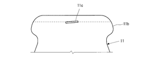
- FIG. 1 is a cross-sectional view of the lip portion 11b of the mouth of the glass container 11, and FIG. 2 is a front view of the same.
- the uppermost part of the glass container mouth is a horizontal flat top surface 11a, and the outer side from the outer end p is an inclined surface, and a lip part 11b bulging annularly is formed on the outer surface of the mouth.
- the range indicated by A at the uppermost part of the glass container mouth is molded by a mold called a guide ring, and the area indicated by B below is molded by a mold called a mouth mold.
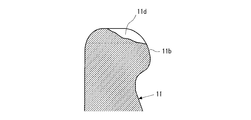
- the scratch 11b may be the starting point, and the glass at the mouth may be chipped, resulting in a top surface defect 11d as shown in FIG.
- Patent Document 1 discloses a technique for detecting a defect on the top of the container mouth.
- this technique it has not been possible to detect the scratches on the lip portion with practical accuracy. This is because the reflected light due to the scratches on the lip portion is slight, and the reflection caused by the slight step portion of the boundary 11e between A and B (because it is a boundary between the guide ring and the mouth mold, a slight step portion is easily formed on the glass surface) This is because it is difficult to distinguish the reflected light from light and lip scratches, and the lip scratches 11c have various shapes and may be tilted as shown in FIG. is there.
- An object of the present invention is to make it possible to accurately detect a scratch on the lip of the glass container mouth.
- the present invention is directed to an inspection method for inspecting a scratch on a lip portion by projecting light from above to an inspection position of a rotating glass container mouth and scanning in the radial direction of the mouth with a line sensor provided above the front of the inspection position. Because Search the line data of each line of the line sensor from the inner side to the outer side of the mouth, The data has a region exceeding the edge signal threshold (EL) caused by the reflected light of the lip portion inclined surface, When the width of the region is larger than the edge width threshold (EW), an address obtained by adding a predetermined offset value (OFS) to the address (GE) that first reaches the edge signal threshold (EL) is used as the inspection gate start position address (GES).
- EL edge signal threshold
- EW edge width threshold
- a predetermined inspection gate width value is added to the inspection gate start position address (GES) to obtain an inspection gate end position address (GEE). From the start position address (GES) to the end position address (GEE) is set as an inspection gate which is a range to be inspected.
- the line data A of each line of the line sensor and the line data B of a line advanced by a predetermined difference interval (FP) from the line are subjected to differential processing in the inspection gate, and the differential data is a predetermined differential threshold (TH).
- the glass container mouth lip portion is characterized in that it is determined that there is a scratch on the lip when the difference total number of elements, which is the sum of the number of elements in the difference execution count (VS), is larger than a predetermined difference element number threshold (PXL).
- PXL predetermined difference element number threshold
- the present invention sets an inspection gate which is a range to be inspected based on the address of the reflected light of the lip portion, for example, even when the center of the container is displaced from the rotation axis and the container is shaken by rotation,
- the starting position of the gate can be set accurately, and it is possible to accurately inspect the lip scratch without being affected by various noises.
- the edge signal threshold (EL) and the offset value (OFS) are appropriately determined in consideration of the cross-sectional shape and size of the mouth, the specifications of the line sensor, and the like.
- the convergence angle ⁇ 1 of the projected light in the front view is set to 44 ° to 52 °, the reflected light is not affected by the shape or inclination of the scratch, and the detection accuracy of the lip scratch is improved.
- a more preferable range of the convergence angle ⁇ 1 is 46 ° to 50 °.
- a more preferable range of the convergence angle ⁇ 2 is 16 ° to 20 °.
- the present invention is also the glass container mouth lip damage inspection method according to claim 2, wherein an angle formed between an axis of the line sensor and a horizontal plane is 36 ° to 44 °.
- the reflected light of the inclined surface of the lip portion can be suitably used for setting the inspection gate, and the reflected light does not overlap with the reflected light of the lip portion scratches.
- the accuracy of detecting a wound can be improved.
- the present invention searches the line data of each line of the line sensor from the inner side to the outer side of the mouth, If the data does not have an area that exceeds the edge signal threshold (EL),
- EL edge signal threshold
- the present invention can detect the top surface defect using this.
- the present invention also includes a projector that projects light from above to the inspection position of the container mouth, A line sensor which is provided above the front of the inspection position and scans the mouth receiving the reflected light from the container mouth in the radial direction; A drive device that rotationally drives the container so that the container mouth is sequentially projected over the entire circumference; Inspection gate detection means for detecting an inspection gate in response to a signal from the line sensor; Having a lip scratch detection means for detecting a lip scratch in the inspection gate detected by the inspection gate detection means;
- the inspection gate detection means includes Search the line data of each line of the line sensor from the inner side to the outer side of the mouth, If the data has an area that exceeds the edge signal threshold (EL) caused by the reflected light of the lip inclined surface, and the width of the area is larger than the edge width threshold (EW), the edge signal threshold (EL) is reached first.
- EL edge signal threshold
- a predetermined inspection gate width value (WID) is added to the inspection gate start position address (GES) to obtain an inspection gate end position address (GEE). From the start position address (GES) to the end position address (GEE) is set as an inspection gate which is a range to be inspected.
- the lip scratch detection means The line data A of each line of the line sensor and the line data B of a line advanced by a predetermined difference interval (FP) from the line are subjected to differential processing in the inspection gate, and a predetermined difference threshold ( (TH) This operation is repeated one after another from the line data A by a predetermined difference execution number (VS),
- VS predetermined difference execution number
- the glass container mouth lip portion is characterized in that it is determined that there is a scratch on the lip when the difference total number of elements, which is the sum of the number of elements in the difference execution count (VS), is larger than a predetermined difference element number threshold (PXL). It is a wound inspection device.
- the apparatus of the present invention inspects by the inspection method of claim 1, the start position of the range (inspection gate) to be inspected for the lip scratch can be accurately set, and the lip scratch is inspected with high accuracy. Can be done.
- the apparatus of the present invention inspects by the inspection method of claim 2, it is possible to inspect the lip scratches with high accuracy.
- the present invention is also the glass container mouth lip scratch inspection apparatus according to claim 7, wherein an angle formed between an axis of the line sensor and a horizontal plane is 36 ° to 44 °.
- the apparatus according to the present invention inspects by the inspection method of claim 3, it becomes possible to inspect the lip scratches with high accuracy.
- the apparatus of the present invention inspects by the inspection method of claim 4, in addition to being able to inspect the lip scratches with high accuracy, it is also possible to inspect the top surface defect.
- the top surface defect detection means comprises: If the line data does not have an area that exceeds the edge signal threshold (EL), And when the line data has an area exceeding the edge signal threshold (EL) and the width of the area is smaller than the edge width threshold (EW), Count that line as a detection line, The top surface defect is determined when the total number of the detected lines counted after acquiring the line data a predetermined number of times (N times) is larger than a predetermined top surface defect threshold (TWL).
- TWL predetermined top surface defect threshold
- the apparatus according to the present invention inspects by the inspection method of claim 5, in addition to accurately inspecting the lip scratches, it is also possible to inspect the top surface defect.
- the inspection method and inspection apparatus of the present invention can detect the scratches on the glass container mouth lip with high accuracy. In addition, it is possible to simultaneously inspect the top surface defect in which the glass of the mouth portion is broken due to the lip scratch.
- FIG. 1 is a schematic view of a container mouth inspection device 1.
- FIG. 2 is a front view of a projector 2.
- FIG. 2 It is a side view of the light projector.
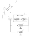
- the glass container lip inspection apparatus 1 includes a projector 2, a line sensor 3, a memory 4, an inspection gate detection means 5, a lip damage detection means 6, and a top surface defect detection means 7. Furthermore, as shown in FIG. 6, an inspection table 8 that rotatably supports the glass container, a driving device 81 that rotationally drives the glass container, a processing device 9 such as a personal computer that processes data captured by the line sensor 3, It has a monitor 91 that displays various processed data.
- the inspection gate detection means 5 further comprises a lip portion inclined surface detection means 5a and an inspection gate creation means 5b.
- the memory 4, inspection gate detection means 5, lip scratch detection means 6, and top surface defect detection means 7 can be set in the processing device 9.
- the driving device 81 the same one as this kind of well-known inspection device can be used.
- the light from the projector 2 is reflected by the top and lip of the mouth of the glass container 11, and the reflected light is received by the line sensor 3.
- Each line data received by the line sensor 3 is stored in the memory 4.
- the line data read from the memory 4 is to be inspected by the detection gate detection means 5 and the detection means of the lip scratch detection means 6 or the top surface defect detection means 7 while the inspection gate is created. Sorted. On the basis of the classification result, the line data is inspected by the lip scratch detection means 6 or the top surface defect detection means 7. If each detection means determines that the failure is detected, a failure signal is output. In addition to being recorded in the memory, the failure signal can be used for the operation of a warning device, the operation of a defective container removal device, and the like.
- Step 101 Is the data processing command ON? Is determined first, and if it is YES, Step 102: Proceed to data processing (detection of defect), an inspection gate is created by the inspection gate detection means 5, and an inspection is performed by the lip portion damage detection means 6 or the top surface defect detection means 7. After this, Step 103 ... Is it defective? If YES, step 104... Proceeds to step 104... Records defect and the defect information is recorded in the memory of the computer. If NO, the process proceeds to step 105 as it is. Step 105: Returning to the step 101 from the next data processing command, the above processing (steps 101 to 105) is repeated for the next line data.
- the glass container 11 is rotatably supported on the turntable 8 and is inspected while being rotated by the drive device 81.
- the light projector 2 condenses the four LEDs 21 by the Fresnel lens 22 to increase the brightness.
- the irradiation range at the inspection position is about 10 mm in diameter.
- the convergence angle ⁇ 1 in the front view of the projected light is about 48 °, and the convergence angle ⁇ 2 in the side view is about 18 °.
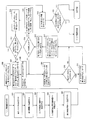
- FIG. 9 is a flowchart for creating an inspection gate
- FIG. 10 is an explanatory diagram of an example of creating an inspection gate.
- the edge signal threshold EL and the edge width threshold EW are set by setting the edge signal threshold EL and the edge width threshold EW. These values are determined in advance according to the type of container to be inspected.
- the offset value OFS is set by setting the offset value OFS.
- the offset value OFS is the number of elements for determining the inspection gate start position address GES in addition to the address (inspection gate edge address GE) that first reaches the edge signal threshold (EL), and depends on the type of container to be inspected in advance.
- the inspection gate width value WID is set by setting the inspection gate width value WID.
- the gate width value WID is determined in advance according to the type of container to be inspected.
- Step 204 By setting the address of the data, the address of the memory for storing the data is set, Step 205... Processing for clearing the memory address save area is performed. Thereafter, the following processing is performed on the line data of each address read from the memory.
- Step 206 The line data is searched from the inner side to the outer side by searching from the left end address of the line data.
- the top surface defect inspection by the top surface defect detection means is performed for the line data, and in the case of YES, Step 208 ... Is the data larger than the edge width threshold EW? Is determined.
- step 209 Is the next address searched and is there any data larger than the edge signal threshold EL?
- the top surface defect inspection by the top surface defect detection means is performed, and in the case of YES, Step 210... Processing for calculating the inspection gate edge address GE is performed.
- steps 201 to 210 are processed by the lip portion inclined surface detecting means 5a, and steps 211 and after are processed by the inspection gate creating means 5b.
- Step 211... In the process of calculating the inspection gate start position address GES from the offset value, an address obtained by adding the offset value OFS to the inspection gate edge address GE is set as the inspection gate start position address GES.
- Step 212... The inspection gate end position address GEE is calculated from the inspection gate width value, and the inspection gate is created, so that the address obtained by adding the inspection gate width value WID to the inspection gate start position address GES is set as the end position address GEE. Then, the inspection gate from the inspection gate start position address GES to the inspection gate end position address GEE is created. Step 213 ...
- Step 214 the line data in which the inspection gates are created by saving the data in the order of the fetched line data is sequentially saved in the memory, and each line data is inspected by the lip damage detection means.
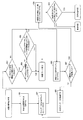
- FIG. 11 is a flowchart for detecting a lip scratch.
- Step 301 Setting the difference filter F sets the difference filter F.
- the difference filter F is a difference between the two line data in the inspection gate.
- Step 302 Setting the difference interval FP sets the difference interval FP.
- each line data is subjected to differential processing with the line data ahead of the FP.
- the FP can be 3 to 10, for example.
- the lip part flaw difference threshold value TH is set by setting the lip part flaw difference threshold value TH.
- the lip flaw difference threshold TH is determined in advance according to the type of container to be inspected.
- Step 304 ...
- the difference element number threshold value PXL is set by setting the lip flaw difference element number threshold value PXL.
- the difference element number threshold value PXL is determined in advance depending on the type of container to be inspected.
- the difference execution count VS is set by setting the difference execution count VS. As a result, VS pieces of difference data are handled as one set.
- the VS can be set to 2 to 10, for example.
- Step 306 First line data is loaded and set as fetched data A 307... FP-th line data advanced from the line data of fetched data A and fetched as data B Step 308.
- Step 309 The difference data of the voltages of the captured data A and B in the inspection gate is created by subtracting the captured data A and the captured data B advanced by FP using F.
- Step 310 Is the difference data larger than TH? If YES, the process proceeds to step 311. If NO, the process proceeds to step 312. If yes, Step 311... After calculating the number of elements of data greater than TH and saving, Step 312...
- next line data is loaded and taken as fetched data A, and the line data advanced by FP from the line data is loaded and fetched data B is processed.
- the “next line data” here is the next line data of the “capture data A” in step 309.
- Step 313 After the process of comparing the captured data A and the captured data B, Step 314 ... Have you compared VS times? Is determined. This is for determining the lip scratch from the difference data of VS times. If NO, steps 309 to 314 are repeated. If YES, Step 315... Load the number of elements of data larger than TH for VS times, add all, and save as the total number of difference elements.
- Step 316 This is a process of counting the number of elements whose voltage is greater than the lip flaw difference threshold TH in each difference data for VS times, summing the VS times, and saving it in the memory. afterwards, Step 316...
- the next line data is loaded and processed as fetched data A.
- the “next line data” here is the next line data of the “capture data A” in step 313.
- Step 317 Did the predetermined line data be loaded and used as fetched data A? Is determined.
- the predetermined line data may be arbitrarily determined so that the process of step 315 is performed on all the line data of the entire circumference of the container mouth. For example, the ⁇ N ⁇ (VS + FP) +2 ⁇ th line It can be data.
- step 317 If NO in step 317, the processing from step 307 to step 317 is repeated. If YES, Step 318... Load all the difference total elements saved in step 315 by loading all the difference total elements. Step 319. Is any of the total number of differential elements larger than PXL? Is determined. If there is at least one difference element number threshold PXL out of all the difference total elements, it is determined that there is a lip scratch, and if there is no one, it is determined that the product is non-defective (no lip scratch).
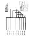
- the second line data for acquisition and the fifth line data for acquisition are subjected to differential processing (II)
- the third line data for acquisition and the sixth line data for acquisition are subjected to differential processing (III)
- the fourth line data for acquisition Then, the seventh processing line data is subjected to difference processing (IV), and the fifth processing line data and the eighth processing line data are subjected to differential processing (V).
- each difference data is compared with the lip scratch difference threshold TH (step 310), the number of elements larger than this is obtained (step 311), and the lip scratch difference threshold for all of the difference processes (I) to (V).
- the total number of elements greater than TH is summed to determine the total number of differential elements (step 315), and the lip damage is determined by comparison with the differential element count threshold PXL (step 319).
- the lip damage is determined by setting the difference processing result from the first line data to the fifth line data to be one set. Thereafter, the lip damage is determined by setting a difference processing result from the next 6th line data to 10th line data as one set.
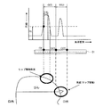
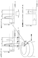
- FIG. 13 is an explanatory diagram of the difference processing.
- Line data for the A line is shown in the upper left.
- the line data of the B line advanced FP from the A line is shown in the upper right. Since the A line has a lip scratch, the voltage of the inspection gate (between WID) is high.
- the result of differential processing of the line data of the A line and the B line is shown in the lower right.
- the difference process is performed by subtracting the voltage within the inspection gate (between WIDs). In the difference result, the number of elements larger than the lip scratch difference threshold TH is calculated (step 311).
- FIG. 14 is a flowchart of the top surface defect detection.
- Step 401 After the process of setting the top surface defect threshold TWL, Step 402 ... By searching from the left end address of the line data, the line data is searched from the inside to the outside of the mouth, Step 403: Is there data that exceeds the edge signal threshold EL? If YES, the process proceeds to step 404. If NO, the process proceeds to step 406. Step 404 ... Is the data larger than the edge width threshold EW? If NO, the process proceeds to step 405. If YES, the process returns to the inspection gate detection means. Step 405... Is there data larger than the edge signal threshold EL by searching for the next address?
- Step 406 The number of detected lines is counted and saved. The number of detected lines is counted (1) If NO is determined in step 403, (2) If NO is determined in step 405, It is. That is, (1) When the line data does not have an area exceeding the edge signal threshold EL, (2) This is a case where the line data has an area exceeding the edge signal threshold EL and the width of the area is smaller than the edge width threshold EW.
- Step 407 Has the Nth line data been processed? If NO in step 408, the next line data is processed, and the processing of 402 to 407 is repeated until the Nth line data is processed.
- Step 409 By loading the count of the number of detected lines up to the N-th time, the total number of detected lines in step 406 is loaded from the first line data to the N-th line data, Step 410 ... Is the number of detected lines counted up to the Nth time larger than TWL?
- TWL top surface defect threshold
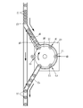
- the inspection apparatus of the present invention is used by being attached to, for example, the inspection station 12 shown in FIG.
- containers 11 sent by a conveyor 13 are guided to a carry-in bypass 14 where they are aligned at a fixed interval by a feed worm 15 and then sent to an inspection station 12.
- the fed container 11 is fitted and captured by the intermittently rotating star wheel 16, and is thereby intermittently forwarded in the order of inspection position A, inspection position B, and inspection position C, and model number recognition and predetermined inspection are performed.
- a container that is determined to be non-defective is introduced into the carry-out bypass 17, and further introduced into the conveyor 13 and conveyed to another location.
- a defective container is sent to the exclusion position D and rejected.
- Such an inspection station is widely used for inspection of glass products such as glass bottles.
- the inspection apparatus of the present invention can be attached and used at any inspection position of such an inspection station in place of the conventional inspection apparatus.
Landscapes
- Physics & Mathematics (AREA)
- Health & Medical Sciences (AREA)
- Life Sciences & Earth Sciences (AREA)
- Chemical & Material Sciences (AREA)
- Analytical Chemistry (AREA)
- Biochemistry (AREA)
- General Health & Medical Sciences (AREA)
- General Physics & Mathematics (AREA)
- Immunology (AREA)
- Pathology (AREA)
- Investigating Materials By The Use Of Optical Means Adapted For Particular Applications (AREA)
Description
本発明は、ガラス容器口部外面に環状に膨出するリップ部の傷を検査するためのガラス容器口リップ部傷の検査方法及び装置に関する。
図1はガラス容器11の口部のリップ部11bの断面図、図2は同じく正面図である。ガラス容器口部の最上部は水平な平面の天面11aで、その外端pから外側が傾斜面となり、口部外面に環状に膨出するリップ部11bが形成されている。
ガラス容器口部の最上部のAで示される範囲は、ガイドリングと呼ばれる型で成形され、その下のBで示される範囲は口型と呼ばれる型で成形される。これらの型が摩耗してくると、ガイドリングと口型の間にガラスが入り込み、AとBの境界11eの付近に突起状の傷11bが形成される。また、この傷11bが起点となって口部のガラスが欠け、図3に示すような天面欠損11dが生じることがある。
ガラス容器口部の最上部のAで示される範囲は、ガイドリングと呼ばれる型で成形され、その下のBで示される範囲は口型と呼ばれる型で成形される。これらの型が摩耗してくると、ガイドリングと口型の間にガラスが入り込み、AとBの境界11eの付近に突起状の傷11bが形成される。また、この傷11bが起点となって口部のガラスが欠け、図3に示すような天面欠損11dが生じることがある。
下記特許文献1には、容器口部天面の欠陥を検出する技術が開示されている。しかし、この技術では、リップ部の傷を実用的に精度よく検出することはできなかった。それは、リップ部傷による反射光が僅かであること、前記AとBの境界11eの僅かな段部(ガイドリングと口型の境界なので、ガラス面に僅かな段部ができやすい)で生じる反射光とリップ部傷による反射光の区別が困難なこと、リップ部傷11cの形状が様々で図3に示すように傾いて形成される場合もあること、などが誤判定の原因となるからである。
本発明は、ガラス容器口リップ部の傷を精度よく検出できるようにすることを課題とするものである。
〔請求項1〕
本発明は、回転するガラス容器口部の検査位置に上方から投光し、該検査位置の正面上方に設けたラインセンサで口部の半径方向に走査してリップ部の傷を検査する検査方法であって、
前記ラインセンサの各ラインのラインデータを前記口部の内側方向から外側方向に向かってサーチし、
そのデータがリップ部傾斜面の反射光によって生じるエッジ信号閾値(EL)を越える領域を有し、
該領域の幅がエッジ幅閾値(EW)より大きい場合、最初にエッジ信号閾値(EL)に達したアドレス(GE)に所定のオフセット値(OFS)を加えたアドレスを検査ゲート開始位置アドレス(GES)とし、
該検査ゲート開始位置アドレス(GES)に所定の検査ゲート幅値(WID)を加えて検査ゲートの終了位置アドレス(GEE)とし、
前記開始位置アドレス(GES)から終了位置アドレス(GEE)までを、検査を行う範囲である検査ゲートとし、
前記ラインセンサの各ラインのラインデータAと、そのラインよりも所定の差分間隔(FP)進んだラインのラインデータBを検査ゲート内において差分処理し、その差分データが所定の差分閾値(TH)より大きいデータの素子数を求め、
この操作を前記ラインデータAから次々に所定の差分実施回数(VS)繰り返し、
差分実施回数(VS)における前記素子数の合計である差分総素子数が所定の差分素子数閾値(PXL)より大きい場合に、リップ部傷有りと判定することを特徴とするガラス容器口リップ部傷の検査方法である。
本発明は、回転するガラス容器口部の検査位置に上方から投光し、該検査位置の正面上方に設けたラインセンサで口部の半径方向に走査してリップ部の傷を検査する検査方法であって、
前記ラインセンサの各ラインのラインデータを前記口部の内側方向から外側方向に向かってサーチし、
そのデータがリップ部傾斜面の反射光によって生じるエッジ信号閾値(EL)を越える領域を有し、
該領域の幅がエッジ幅閾値(EW)より大きい場合、最初にエッジ信号閾値(EL)に達したアドレス(GE)に所定のオフセット値(OFS)を加えたアドレスを検査ゲート開始位置アドレス(GES)とし、
該検査ゲート開始位置アドレス(GES)に所定の検査ゲート幅値(WID)を加えて検査ゲートの終了位置アドレス(GEE)とし、
前記開始位置アドレス(GES)から終了位置アドレス(GEE)までを、検査を行う範囲である検査ゲートとし、
前記ラインセンサの各ラインのラインデータAと、そのラインよりも所定の差分間隔(FP)進んだラインのラインデータBを検査ゲート内において差分処理し、その差分データが所定の差分閾値(TH)より大きいデータの素子数を求め、
この操作を前記ラインデータAから次々に所定の差分実施回数(VS)繰り返し、
差分実施回数(VS)における前記素子数の合計である差分総素子数が所定の差分素子数閾値(PXL)より大きい場合に、リップ部傷有りと判定することを特徴とするガラス容器口リップ部傷の検査方法である。
本発明は、リップ部の反射光のアドレスに基づいて検査を行う範囲である検査ゲートを設定するので、例えば、容器の中心が回転軸とずれ、容器が回転によってブレるような場合でも、検査ゲートの開始位置を正確に設定することができ、種々のノイズに影響されずに、リップ部傷の検査を精度よく行うことが可能となる。
容器口部の検査位置に上方から投光すること、ラインセンサを検査位置の正面上方に設け、口部の半径方向に内側から外側に向かって走査することで、適切なリップ部の反射光を捉えることができる。
容器口部の検査位置に上方から投光すること、ラインセンサを検査位置の正面上方に設け、口部の半径方向に内側から外側に向かって走査することで、適切なリップ部の反射光を捉えることができる。
エッジ信号閾値(EL)、オフセット値(OFS)は、口部の断面形状及び大きさ、ラインセンサの仕様等を考慮して適宜定める。
〔請求項2〕
また本発明は、前記投光した光の正面視における収束角度θ1が44°~52°、側面視における収束角度θ2が14°~22°である請求項1に記載のガラス容器口リップ部傷の検査方法である。
また本発明は、前記投光した光の正面視における収束角度θ1が44°~52°、側面視における収束角度θ2が14°~22°である請求項1に記載のガラス容器口リップ部傷の検査方法である。
投光した光の正面視における収束角度θ1を44°~52°にすることで、傷の形状や傾きに左右されない反射光となり、リップ部傷の検出精度が向上する。収束角度θ1の更に好ましい範囲は46°~50°である。
投光した光の側面視における収束角度θ2を14°~22°にすることで、図1の境界11eにできやすい僅かな段部における反射光量が減少し、リップ部傷の検出精度が向上する。収束角度θ2の更に好ましい範囲は16°~20°である。
〔請求項3〕
また本発明は、前記ラインセンサの軸線と水平面のなす角度が36°~44°である請求項2に記載のガラス容器口リップ部傷の検査方法である。
また本発明は、前記ラインセンサの軸線と水平面のなす角度が36°~44°である請求項2に記載のガラス容器口リップ部傷の検査方法である。
ラインセンサの軸線を36°~44°にすることで、リップ部傾斜面の反射光を検査ゲートの設定に好適に利用でき、この反射光がリップ部傷の反射光と重ならないようにしてリップ部傷の検出精度を向上できる。
〔請求項4〕
また本発明は、前記ラインセンサの各ラインのラインデータを前記口部の内側方向から外側方向に向かってサーチし、
そのデータがエッジ信号閾値(EL)を越える領域を有しない場合、
及びそのデータがエッジ信号閾値(EL)を越える領域を有し該領域の幅がエッジ幅閾値(EW)より小さい場合に天面欠損検査を行う請求項1~3のいずれかに記載のガラス容器口リップ部傷の検査方法である。
また本発明は、前記ラインセンサの各ラインのラインデータを前記口部の内側方向から外側方向に向かってサーチし、
そのデータがエッジ信号閾値(EL)を越える領域を有しない場合、
及びそのデータがエッジ信号閾値(EL)を越える領域を有し該領域の幅がエッジ幅閾値(EW)より小さい場合に天面欠損検査を行う請求項1~3のいずれかに記載のガラス容器口リップ部傷の検査方法である。
〔請求項5〕
また本発明は、ラインデータがエッジ信号閾値(EL)を越える領域を有しない場合、
及びラインデータがエッジ信号閾値(EL)を越える領域を有し該領域の幅がエッジ幅閾値(EW)より小さい場合、
そのラインを検出ラインとしてカウントし、
所定の回数(N回)ラインデータを取り込んだ後のカウントされた前記検出ラインの数の合計が所定の天面欠損閾値(TWL)よりも多い場合に天面欠損と判定する請求項4に記載のガラス容器口リップ部傷の検査方法である。
また本発明は、ラインデータがエッジ信号閾値(EL)を越える領域を有しない場合、
及びラインデータがエッジ信号閾値(EL)を越える領域を有し該領域の幅がエッジ幅閾値(EW)より小さい場合、
そのラインを検出ラインとしてカウントし、
所定の回数(N回)ラインデータを取り込んだ後のカウントされた前記検出ラインの数の合計が所定の天面欠損閾値(TWL)よりも多い場合に天面欠損と判定する請求項4に記載のガラス容器口リップ部傷の検査方法である。
口部の天面欠損により、リップ部傾斜面の反射光が減少し、又はなくなるので、本発明はこれを利用して天面欠損を検出できる。
〔請求項6〕
また本発明は、上方から容器口部の検査位置に投光する投光器と、
該検査位置の正面上方に設けられ、容器口部からの反射光を受ける口部を半径方向に走査するラインセンサと、
容器口部が順次全周に亘って投光されるように容器を回転駆動する駆動装置と、
前記ラインセンサからの信号を受けて検査ゲートを検出する検査ゲート検出手段と、
前記検査ゲート検出手段で検出した検査ゲートにおいてリップ部傷を検出するリップ部傷検出手段を有し、
前記検査ゲート検出手段が、
前記ラインセンサの各ラインのラインデータを前記口部の内側方向から外側方向に向かってサーチし、
そのデータがリップ部傾斜面の反射光によって生じるエッジ信号閾値(EL)を越える領域を有し、該領域の幅がエッジ幅閾値(EW)より大きい場合、最初にエッジ信号閾値(EL)に達したアドレス(GE)に所定のオフセット値(OFS)を加えたアドレスを検査ゲート開始位置アドレス(GES)とし、
該検査ゲート開始位置アドレス(GES)に所定の検査ゲート幅値(WID)を加えて検査ゲートの終了位置アドレス(GEE)とし、
前記開始位置アドレス(GES)から終了位置アドレス(GEE)までを、検査を行う範囲である検査ゲートとし、
前記リップ部傷検出手段が、
前記ラインセンサの各ラインのラインデータAと、そのラインよりも所定の差分間隔(FP)進んだラインのラインデータBを検査ゲート内において差分処理し、その差分データのなかで所定の差分閾値(TH)より大きい素子数を求め、
この操作を前記ラインデータAから次々に所定の差分実施回数(VS)繰り返し、
差分実施回数(VS)における前記素子数の合計である差分総素子数が所定の差分素子数閾値(PXL)より大きい場合に、リップ部傷有りと判定することを特徴とするガラス容器口リップ部傷の検査装置である。
また本発明は、上方から容器口部の検査位置に投光する投光器と、
該検査位置の正面上方に設けられ、容器口部からの反射光を受ける口部を半径方向に走査するラインセンサと、
容器口部が順次全周に亘って投光されるように容器を回転駆動する駆動装置と、
前記ラインセンサからの信号を受けて検査ゲートを検出する検査ゲート検出手段と、
前記検査ゲート検出手段で検出した検査ゲートにおいてリップ部傷を検出するリップ部傷検出手段を有し、
前記検査ゲート検出手段が、
前記ラインセンサの各ラインのラインデータを前記口部の内側方向から外側方向に向かってサーチし、
そのデータがリップ部傾斜面の反射光によって生じるエッジ信号閾値(EL)を越える領域を有し、該領域の幅がエッジ幅閾値(EW)より大きい場合、最初にエッジ信号閾値(EL)に達したアドレス(GE)に所定のオフセット値(OFS)を加えたアドレスを検査ゲート開始位置アドレス(GES)とし、
該検査ゲート開始位置アドレス(GES)に所定の検査ゲート幅値(WID)を加えて検査ゲートの終了位置アドレス(GEE)とし、
前記開始位置アドレス(GES)から終了位置アドレス(GEE)までを、検査を行う範囲である検査ゲートとし、
前記リップ部傷検出手段が、
前記ラインセンサの各ラインのラインデータAと、そのラインよりも所定の差分間隔(FP)進んだラインのラインデータBを検査ゲート内において差分処理し、その差分データのなかで所定の差分閾値(TH)より大きい素子数を求め、
この操作を前記ラインデータAから次々に所定の差分実施回数(VS)繰り返し、
差分実施回数(VS)における前記素子数の合計である差分総素子数が所定の差分素子数閾値(PXL)より大きい場合に、リップ部傷有りと判定することを特徴とするガラス容器口リップ部傷の検査装置である。
本発明装置は、請求項1の検査方法で検査を行うので、リップ部傷の検査を行うべき範囲(検査ゲート)の開始位置を正確に設定することができ、リップ部傷の検査を精度よく行うことが可能となる。
〔請求項7〕
また本発明は、前記投光器の光の正面視における収束角度θ1が44°~52°、側面視における収束角度θ2が14°~22°である請求項6に記載のガラス容器口リップ部傷の検査装置である。
また本発明は、前記投光器の光の正面視における収束角度θ1が44°~52°、側面視における収束角度θ2が14°~22°である請求項6に記載のガラス容器口リップ部傷の検査装置である。
本発明装置は、請求項2の検査方法で検査を行うので、リップ部傷の検査を精度よく行うことが可能となる。
〔請求項8〕
また本発明は、前記ラインセンサの軸線と水平面のなす角度が36°~44°である請求項7に記載のガラス容器口リップ部傷の検査装置である。
また本発明は、前記ラインセンサの軸線と水平面のなす角度が36°~44°である請求項7に記載のガラス容器口リップ部傷の検査装置である。
本発明装置は、請求項3の検査方法で検査を行うので、リップ部傷の検査を精度よく行うことが可能となる。
〔請求項9〕
また本発明は、前記検査ゲート検出手段からの信号を受けて、天面欠損を検出する天面欠損検出手段を有する請求項6~8のいずれかに記載のガラス容器口リップ部傷の検査装置である。
また本発明は、前記検査ゲート検出手段からの信号を受けて、天面欠損を検出する天面欠損検出手段を有する請求項6~8のいずれかに記載のガラス容器口リップ部傷の検査装置である。
本発明装置は、請求項4の検査方法で検査を行うので、リップ部傷の検査を精度よく行えることに加えて、天面欠損の検査も行うことができる。
〔請求項10〕
また本発明は、前記天面欠損検出手段が、
ラインデータがエッジ信号閾値(EL)を越える領域を有しない場合、
及びラインデータがエッジ信号閾値(EL)を越える領域を有し該領域の幅がエッジ幅閾値(EW)より小さい場合、
そのラインを検出ラインとしてカウントし、
所定の回数(N回)ラインデータを取り込んだ後のカウントされた前記検出ラインの数の合計が所定の天面欠損閾値(TWL)よりも多い場合に天面欠損と判定する請求項9に記載のガラス容器口リップ部傷の検査装置である。
また本発明は、前記天面欠損検出手段が、
ラインデータがエッジ信号閾値(EL)を越える領域を有しない場合、
及びラインデータがエッジ信号閾値(EL)を越える領域を有し該領域の幅がエッジ幅閾値(EW)より小さい場合、
そのラインを検出ラインとしてカウントし、
所定の回数(N回)ラインデータを取り込んだ後のカウントされた前記検出ラインの数の合計が所定の天面欠損閾値(TWL)よりも多い場合に天面欠損と判定する請求項9に記載のガラス容器口リップ部傷の検査装置である。
本発明装置は、請求項5の検査方法で検査を行うので、リップ部傷の検査を精度よく行えることに加えて、天面欠損の検査も行うことができる。
本発明の検査方法及び検査装置は、ガラス容器口リップ部の傷を精度よく検出できる。また、リップ部傷が起点となって口部のガラスが欠けた天面欠損も同時に検査することもできる。
図4に示すように、ガラス容器口リップ部傷検査装置1は投光器2、ラインセンサ3、メモリ4、検査ゲート検出手段5、リップ部傷検出手段6、天面欠損検出手段7を有する。さらに、図6に示すように、ガラス容器を回転可能に支持する検査台8、ガラス容器を回転駆動する駆動装置81、ラインセンサ3で撮像したデータを処理する、パーソナルコンピュータなどの処理装置9、処理した各種データを表示するモニタ91を有する。
検査ゲート検出手段5は、さらにリップ部傾斜面検出手段5aと検査ゲート作成手段5bからなる。メモリ4、検査ゲート検出手段5、リップ部傷検出手段6、天面欠損検出手段7は処理装置9内に設定することができる。駆動装置81は、従来周知のこの種の検査装置と同じものを使用できる。
検査ゲート検出手段5は、さらにリップ部傾斜面検出手段5aと検査ゲート作成手段5bからなる。メモリ4、検査ゲート検出手段5、リップ部傷検出手段6、天面欠損検出手段7は処理装置9内に設定することができる。駆動装置81は、従来周知のこの種の検査装置と同じものを使用できる。
投光器2からの光はガラス容器11の口部天面及びリップ部で反射し、その反射光をラインセンサ3で受光する。ラインセンサ3で受光した各ラインデータはメモリ4に蓄積される。メモリ4から読み出されたラインデータは、検査ゲート検出手段5で検査ゲートが作成されると共に、リップ部傷検出手段6、又は天面欠損検出手段7のどちらの検出手段で検査されるべきか分別される。その分別結果に基づき、ラインデータはリップ部傷検出手段6、又は天面欠損検出手段7で検査される。各検出手段で不良と判定された場合は、不良信号が出力される。不良信号はメモリに記録される他、警告装置の作動や不良容器排除装置の作動などに利用することができる。
図5により、検査装置1における処理の概要を説明する。
ステップ101……データ処理指令ONか?
という判定が先ず行われ、YESであると、
ステップ102……データ処理(不良を検出)する
へ進み、検査ゲート検出手段5で検査ゲートが作成されると共に、リップ部傷検出手段6、又は天面欠損検出手段7で検査が行われる。この後、
ステップ103……不良か?
という判定が行われ、YESであると
ステップ104……不良を記録する
へ進み、コンピュータのメモリに不良の情報が記録され、ステップ105へ進む。NOであると、そのままステップ105へ進む。
ステップ105……次のデータ処理指令
からはステップ101へ戻り、次のラインデータについて上記の処理(ステップ101~105)が繰り返される。
ステップ101……データ処理指令ONか?
という判定が先ず行われ、YESであると、
ステップ102……データ処理(不良を検出)する
へ進み、検査ゲート検出手段5で検査ゲートが作成されると共に、リップ部傷検出手段6、又は天面欠損検出手段7で検査が行われる。この後、
ステップ103……不良か?
という判定が行われ、YESであると
ステップ104……不良を記録する
へ進み、コンピュータのメモリに不良の情報が記録され、ステップ105へ進む。NOであると、そのままステップ105へ進む。
ステップ105……次のデータ処理指令
からはステップ101へ戻り、次のラインデータについて上記の処理(ステップ101~105)が繰り返される。
ガラス容器11は、図6に示すように、回転台8の上で回転可能に支持され、駆動装置81によって回転しながら検査される。投光器2は、図7、8に示すように、4個のLED21をフレネルレンズ22により集光させて高輝度にしている。検査位置における照射範囲は直径10mm程度となっている。投光した光の正面視における収束角度θ1は約48°、側面視における収束角度θ2は約18°である。
(検査ゲート作成)
次に、図9,10に基づいて、ラインセンサの各ラインデータにおける検査ゲートの検出について説明する。図9は検査ゲート作成のフローチャート、図10は検査ゲート作成例の説明図である。
図9において、
ステップ201……エッジ信号閾値EL、エッジ幅閾値EWを設定する
によってエッジ信号閾値EL、エッジ幅閾値EWが設定される。これらの値は、検査する容器の種類により、予め定めておく。
ステップ202……オフセット値OFSを設定する
によってオフセット値OFSが設定される。オフセット値OFSは、最初にエッジ信号閾値(EL)に達したアドレス(検査ゲートエッジアドレスGE)に加えて検査ゲート開始位置アドレスGESを決定するための素子数で、検査する容器の種類により、予め定めておく。
ステップ203……検査ゲート幅値WIDを設定する
によって検査ゲート幅値WIDが設定される。ゲート幅値WIDは、検査する容器の種類により、予め定めておく。
ステップ204……データのアドレスを設定する
によってデータを格納するメモリのアドレスが設定され、
ステップ205……メモリのアドレスセーブエリアをクリアする
という処理が行われる。この後、メモリより読み出される各アドレスのラインデータについて以下の処理が行われる。
次に、図9,10に基づいて、ラインセンサの各ラインデータにおける検査ゲートの検出について説明する。図9は検査ゲート作成のフローチャート、図10は検査ゲート作成例の説明図である。
図9において、
ステップ201……エッジ信号閾値EL、エッジ幅閾値EWを設定する
によってエッジ信号閾値EL、エッジ幅閾値EWが設定される。これらの値は、検査する容器の種類により、予め定めておく。
ステップ202……オフセット値OFSを設定する
によってオフセット値OFSが設定される。オフセット値OFSは、最初にエッジ信号閾値(EL)に達したアドレス(検査ゲートエッジアドレスGE)に加えて検査ゲート開始位置アドレスGESを決定するための素子数で、検査する容器の種類により、予め定めておく。
ステップ203……検査ゲート幅値WIDを設定する
によって検査ゲート幅値WIDが設定される。ゲート幅値WIDは、検査する容器の種類により、予め定めておく。
ステップ204……データのアドレスを設定する
によってデータを格納するメモリのアドレスが設定され、
ステップ205……メモリのアドレスセーブエリアをクリアする
という処理が行われる。この後、メモリより読み出される各アドレスのラインデータについて以下の処理が行われる。
ステップ206……ラインデータの左端アドレスからサーチする
によってラインデータを口部の内側方向から外側方向に向かってサーチし、
ステップ207……データがエッジ信号閾値ELを超えるものはあるか?
という判定が行われ、NOである場合は、そのラインデータについて天面欠損検出手段による天面欠損検査が行われ、YESの場合は、
ステップ208……データがエッジ幅閾値EWより大きいか?
という判定が行われる。NOの場合は
ステップ209……次アドレスをサーチしてエッジ信号閾値ELより大きいデータはあるか?
の判定が行われ、NOの場合は天面欠損検出手段による天面欠損検査が行われ、YESの場合は、
ステップ210……検査ゲートエッジアドレスGEが算出される
という処理が行われる。エッジ信号閾値ELより大きい領域が1つの場合は、最初にELに達したアドレスが検査ゲートエッジアドレスGEとなり、2つある場合は第2の領域において最初にELに達したアドレスがGEとなる。
以上、ステップ201~210までがリップ部傾斜面検出手段5aで処理され、ステップ211以降が検査ゲート作成手段5bで処理される。
によってラインデータを口部の内側方向から外側方向に向かってサーチし、
ステップ207……データがエッジ信号閾値ELを超えるものはあるか?
という判定が行われ、NOである場合は、そのラインデータについて天面欠損検出手段による天面欠損検査が行われ、YESの場合は、
ステップ208……データがエッジ幅閾値EWより大きいか?
という判定が行われる。NOの場合は
ステップ209……次アドレスをサーチしてエッジ信号閾値ELより大きいデータはあるか?
の判定が行われ、NOの場合は天面欠損検出手段による天面欠損検査が行われ、YESの場合は、
ステップ210……検査ゲートエッジアドレスGEが算出される
という処理が行われる。エッジ信号閾値ELより大きい領域が1つの場合は、最初にELに達したアドレスが検査ゲートエッジアドレスGEとなり、2つある場合は第2の領域において最初にELに達したアドレスがGEとなる。
以上、ステップ201~210までがリップ部傾斜面検出手段5aで処理され、ステップ211以降が検査ゲート作成手段5bで処理される。
ステップ211……オフセット値により検査ゲート開始位置アドレスGESを算出する
の処理で、検査ゲートエッジアドレスGEにオフセット値OFSを加えたアドレスが検査ゲート開始位置アドレスGESとして設定され、
ステップ212……検査ゲート幅値により検査ゲート終了位置アドレスGEEを算出され、検査ゲートが作成される
によって、検査ゲート開始位置アドレスGESに検査ゲート幅値WIDを加えたアドレスが終了位置アドレスGEEとして設定され、検査ゲート開始位置アドレスGESから検査ゲート終了位置アドレスGEEまでの検査ゲートが作成される。
ステップ213……取り込んだデータ毎に検査ゲートを作成する(取り込み数N回)
という処理で、N番目のラインデータまで、メモリからラインデータを取り込み、そのラインデータ毎にステップ207~214の処理を行う。取り込み数Nは予め設定しておくが、容器口部全周のライン数nよりも若干多い数で、好ましくはn+10からnの1.3倍程度である。
ステップ214……取り込んだラインデータ順にデータをセーブする
によって検査ゲートが作成されたラインデータを順番にメモリにセーブし、各ラインデータについてリップ部傷検出手段による検査が行われる。
の処理で、検査ゲートエッジアドレスGEにオフセット値OFSを加えたアドレスが検査ゲート開始位置アドレスGESとして設定され、
ステップ212……検査ゲート幅値により検査ゲート終了位置アドレスGEEを算出され、検査ゲートが作成される
によって、検査ゲート開始位置アドレスGESに検査ゲート幅値WIDを加えたアドレスが終了位置アドレスGEEとして設定され、検査ゲート開始位置アドレスGESから検査ゲート終了位置アドレスGEEまでの検査ゲートが作成される。
ステップ213……取り込んだデータ毎に検査ゲートを作成する(取り込み数N回)
という処理で、N番目のラインデータまで、メモリからラインデータを取り込み、そのラインデータ毎にステップ207~214の処理を行う。取り込み数Nは予め設定しておくが、容器口部全周のライン数nよりも若干多い数で、好ましくはn+10からnの1.3倍程度である。
ステップ214……取り込んだラインデータ順にデータをセーブする
によって検査ゲートが作成されたラインデータを順番にメモリにセーブし、各ラインデータについてリップ部傷検出手段による検査が行われる。
(リップ部傷検出)
図11はリップ部傷検出のフローチャートである。同図において、
ステップ301……差分フィルタFを設定する
で差分フィルタFが設定される。差分フィルタFは2つのラインデータを検査ゲート内において差分するものである。
ステップ302……差分間隔FPを設定する
で差分間隔FPが設定される。これにより、各ラインデータはそのFP個先のラインデータと差分処理を行うことになる。FPは、例えば3~10とすることができる。
ステップ303……リップ部傷差分閾値THを設定する
でリップ部傷差分閾値THが設定される。リップ部傷差分閾値THは検査する容器の種類により、予め定めておく。
ステップ304……リップ部傷差分素子数閾値PXLを設定する
で差分素子数閾値PXLを設定する。差分素子数閾値PXLは検査する容器の種類により、予め定めておく。
ステップ305……差分実施回数VSを設定する
で差分実施回数VSが設定される。これにより、VS個の差分データが1セットとして取り扱われることになる。VSは、例えば2~10とすることができる。
図11はリップ部傷検出のフローチャートである。同図において、
ステップ301……差分フィルタFを設定する
で差分フィルタFが設定される。差分フィルタFは2つのラインデータを検査ゲート内において差分するものである。
ステップ302……差分間隔FPを設定する
で差分間隔FPが設定される。これにより、各ラインデータはそのFP個先のラインデータと差分処理を行うことになる。FPは、例えば3~10とすることができる。
ステップ303……リップ部傷差分閾値THを設定する
でリップ部傷差分閾値THが設定される。リップ部傷差分閾値THは検査する容器の種類により、予め定めておく。
ステップ304……リップ部傷差分素子数閾値PXLを設定する
で差分素子数閾値PXLを設定する。差分素子数閾値PXLは検査する容器の種類により、予め定めておく。
ステップ305……差分実施回数VSを設定する
で差分実施回数VSが設定される。これにより、VS個の差分データが1セットとして取り扱われることになる。VSは、例えば2~10とすることができる。
ステップ306……1番目のラインデータをロードし、取り込みデータAとする
ステップ307……取り込みデータAのラインデータからFP番目進んだラインデータをロードし、取り込みデータBとする
ステップ308……取り込みデータAと取り込みデータBを比較する
の処理の後、
ステップ309……Fを使用して取り込みデータAとFP進んだ取り込みデータBを差分する
によって、検査ゲート内における取り込みデータA、Bの電圧の差分データが作成される。
ステップ310……差分データがTHより大きいか?
という判定が行われ、YESの場合はステップ311に進み、NOの場合はステップ312に進む。YESの場合、
ステップ311……THより大きいデータの素子数を算出し、セーブする
という処理が行われた後、
ステップ312……次のラインデータをロードし、取り込みデータAとし、そのラインデータからFP進んだラインデータをロードし、取り込みデータBとする
の処理が行われる。ここでいう「次のラインデータ」とは、ステップ309における「取り込みデータA」の次のラインデータである。
ステップ313……取り込みデータAと取り込みデータBを比較する
の処理の後、
ステップ314……VS回比較したか?
の判定が行われる。これは、VS回の差分データからリップ部傷の判定を行うためのものである。NOの場合はステップ309~314が繰り返され、YESの場合は、
ステップ315……VS回分のTHより大きいデータの素子数をロードし、全てを加算し、差分総素子数としてセーブする
の処理を行う。これは、VS回分の各差分データにおいて、電圧がリップ部傷差分閾値THより大きい素子数をカウントし、VS回分を合計し、メモリにセーブする処理である。その後、
ステップ316……次のラインデータをロードし、取り込みデータAとする
という処理が行われる。ここでいう「次のラインデータ」とは、ステップ313における「取り込みデータA」の次のラインデータである。その後、
ステップ317……所定のラインデータをロードし、取り込みデータAとしたか?
の判定が行われる。ここで、所定のラインデータとは、容器口部全周の全てのラインデータについてステップ315の処理が行われるように、任意に定めればよく、例えば{N-(VS+FP)+2}番目のラインデータとすることができる。ステップ317でNOの場合は、ステップ307~ステップ317の処理が繰り返され、YESの場合は、
ステップ318……全ての差分総素子数をロードする
によって、ステップ315でセーブされた全ての差分総素子数をロードし、
ステップ319……全ての差分総素子数の中にPXLより大きいものがあるか?
の判定が行われる。全ての差分総素子数の中に差分素子数閾値PXLより大きいものが1つでもあれば、リップ部傷ありと判定され、1つもなければ良品(リップ部傷なし)と判定される。
ステップ307……取り込みデータAのラインデータからFP番目進んだラインデータをロードし、取り込みデータBとする
ステップ308……取り込みデータAと取り込みデータBを比較する
の処理の後、
ステップ309……Fを使用して取り込みデータAとFP進んだ取り込みデータBを差分する
によって、検査ゲート内における取り込みデータA、Bの電圧の差分データが作成される。
ステップ310……差分データがTHより大きいか?
という判定が行われ、YESの場合はステップ311に進み、NOの場合はステップ312に進む。YESの場合、
ステップ311……THより大きいデータの素子数を算出し、セーブする
という処理が行われた後、
ステップ312……次のラインデータをロードし、取り込みデータAとし、そのラインデータからFP進んだラインデータをロードし、取り込みデータBとする
の処理が行われる。ここでいう「次のラインデータ」とは、ステップ309における「取り込みデータA」の次のラインデータである。
ステップ313……取り込みデータAと取り込みデータBを比較する
の処理の後、
ステップ314……VS回比較したか?
の判定が行われる。これは、VS回の差分データからリップ部傷の判定を行うためのものである。NOの場合はステップ309~314が繰り返され、YESの場合は、
ステップ315……VS回分のTHより大きいデータの素子数をロードし、全てを加算し、差分総素子数としてセーブする
の処理を行う。これは、VS回分の各差分データにおいて、電圧がリップ部傷差分閾値THより大きい素子数をカウントし、VS回分を合計し、メモリにセーブする処理である。その後、
ステップ316……次のラインデータをロードし、取り込みデータAとする
という処理が行われる。ここでいう「次のラインデータ」とは、ステップ313における「取り込みデータA」の次のラインデータである。その後、
ステップ317……所定のラインデータをロードし、取り込みデータAとしたか?
の判定が行われる。ここで、所定のラインデータとは、容器口部全周の全てのラインデータについてステップ315の処理が行われるように、任意に定めればよく、例えば{N-(VS+FP)+2}番目のラインデータとすることができる。ステップ317でNOの場合は、ステップ307~ステップ317の処理が繰り返され、YESの場合は、
ステップ318……全ての差分総素子数をロードする
によって、ステップ315でセーブされた全ての差分総素子数をロードし、
ステップ319……全ての差分総素子数の中にPXLより大きいものがあるか?
の判定が行われる。全ての差分総素子数の中に差分素子数閾値PXLより大きいものが1つでもあれば、リップ部傷ありと判定され、1つもなければ良品(リップ部傷なし)と判定される。
図12は差分間隔FP及び差分実施回数VSの説明図である。同図は、差分間隔FP=3、差分実施回数VS=5の場合を例示している。取り込み1番目のラインデータと、差分間隔FP=3だけ進んだ取り込み4番目のラインデータを差分処理(I)する(ステップ309)。同様にして、取り込み2番目のラインデータと取り込み5番目のラインデータを差分処理(II)、取り込み3番目のラインデータと取り込み6番目のラインデータを差分処理(III)、取り込み4番目のラインデータと取り込み7番目のラインデータを差分処理(IV)、取り込み5番目のラインデータと取り込み8番目のラインデータを差分処理(V)する。差分実施回数VS=5であるので、差分処理(I)~(V)迄の差分結果を1セットとして処理する。すなわち、各差分データをリップ部傷差分閾値THと比較し(ステップ310)、これよりも大きい素子数を求め(ステップ311)、差分処理(I)~(V)の全てについてリップ部傷差分閾値THより大きい素子数を合計して差分総素子数を求め(ステップ315)、差分素子数閾値PXLと比較してリップ部傷の判定を行う(ステップ319)。このように、取り込み1番目のラインデータから取り込み5番目のラインデータまでの差分処理結果を1セットとしてリップ部傷の判定を行う。その後は、次の、取り込み6番目のラインデータから取り込み10番目のラインデータまでの差分処理結果を1セットとしてリップ部傷の判定を行う。
図13は差分処理の説明図である。Aラインのラインデータが左上に示される。AラインからFP番目進んだBラインのラインデータが右上に示される。Aラインにはリップ部傷があるので、検査ゲート(WID間)の電圧が高くなっている。AラインとBラインのラインデータを差分処理した結果が右下に示される。差分処理は、検査ゲート内(WID間)において電圧を引き算することで行われる。差分結果において、リップ部傷差分閾値THより大きい素子の数が算出される(ステップ311)。
(天面欠損検出)
図14は天面欠損検出のフローチャートである。同図において、
ステップ401……天面欠損閾値TWLを設定する
の処理の後、
ステップ402……ラインデータの左端アドレスからサーチする
によってラインデータを口部の内側方向から外側方向に向かってサーチし、
ステップ403……データがエッジ信号閾値ELを超えるものはあるか?
という判定が行われ、YESの場合はステップ404に、NOの場合はステップ406に進む。
ステップ404……データがエッジ幅閾値EWより大きいか?
という判定が行われ、NOの場合はステップ405に進み、YESの場合は検査ゲート検出手段に戻る。
ステップ405……次アドレスをサーチしてエッジ信号閾値ELより大きいデータはあるか?
の判定が行われ、YESの場合は検査ゲート検出手段に戻り、NOの場合はステップ406に進む。
ステップ406……検出ライン数をカウントし、セーブする
の処理が行われる。検出ライン数としてカウントされるのは、
(1)ステップ403でNOと判定された場合、
(2)ステップ405でNOと判定された場合、
である。すなわち、
(1)ラインデータがエッジ信号閾値ELを越える領域を有しない場合、
(2)ラインデータがエッジ信号閾値ELを越える領域を有し該領域の幅がエッジ幅閾値EWより小さい場合
である。
ステップ407……N番目のラインデータを処理したか?
の判定により、NOであれば
ステップ408……次のラインデータを処理する
によって、402~407の処理をN番目のラインデータが処理されるまで繰り返し、ステップ407がYESであれば、
ステップ409……N回目迄の検出ライン数のカウントをロードする
により、1番目のラインデータからN番目のラインデータ迄で、ステップ406で検出ラインとされたライン数の合計がロードされ、
ステップ410……N回目迄にカウントされた検出ライン数がTWLより多いか?
の判定により、ステップ409の検出ラインの合計が天面欠損閾値TWLより多い場合に天面欠損、少ない場合に良品(天面欠損なし)と判定される。
図14は天面欠損検出のフローチャートである。同図において、
ステップ401……天面欠損閾値TWLを設定する
の処理の後、
ステップ402……ラインデータの左端アドレスからサーチする
によってラインデータを口部の内側方向から外側方向に向かってサーチし、
ステップ403……データがエッジ信号閾値ELを超えるものはあるか?
という判定が行われ、YESの場合はステップ404に、NOの場合はステップ406に進む。
ステップ404……データがエッジ幅閾値EWより大きいか?
という判定が行われ、NOの場合はステップ405に進み、YESの場合は検査ゲート検出手段に戻る。
ステップ405……次アドレスをサーチしてエッジ信号閾値ELより大きいデータはあるか?
の判定が行われ、YESの場合は検査ゲート検出手段に戻り、NOの場合はステップ406に進む。
ステップ406……検出ライン数をカウントし、セーブする
の処理が行われる。検出ライン数としてカウントされるのは、
(1)ステップ403でNOと判定された場合、
(2)ステップ405でNOと判定された場合、
である。すなわち、
(1)ラインデータがエッジ信号閾値ELを越える領域を有しない場合、
(2)ラインデータがエッジ信号閾値ELを越える領域を有し該領域の幅がエッジ幅閾値EWより小さい場合
である。
ステップ407……N番目のラインデータを処理したか?
の判定により、NOであれば
ステップ408……次のラインデータを処理する
によって、402~407の処理をN番目のラインデータが処理されるまで繰り返し、ステップ407がYESであれば、
ステップ409……N回目迄の検出ライン数のカウントをロードする
により、1番目のラインデータからN番目のラインデータ迄で、ステップ406で検出ラインとされたライン数の合計がロードされ、
ステップ410……N回目迄にカウントされた検出ライン数がTWLより多いか?
の判定により、ステップ409の検出ラインの合計が天面欠損閾値TWLより多い場合に天面欠損、少ない場合に良品(天面欠損なし)と判定される。
本発明の検査装置は、例えば図16に示す検査ステーション12に取り付けて使用される。同図において、コンベア13によって送られてきた容器11は、搬入バイパス14に導かれ、ここにおいてフィードウォーム15によって一定の間隔に整列された後検査ステーション12へ送り込まれる。送り込まれた容器11は、間欠回転するスターホイール16に嵌合捕捉され、これによって検査ポジションA、検査ポジションB、検査ポジションCの順に間欠的に回送され、型番認識や所定の検査が行われる。このような検査を受けた結果、良品とされた容器は搬出バイパス17に導入され、さらにコンベア13に導入されて他所へ搬送される。一方、不良品とされた容器は排除ポジションDまで回送されて排除される。このような検査ステーションはガラスびんなどのガラス製品の検査に汎用されているものである。本発明の検査装置は、このような検査ステーションの任意の検査ポジションに、従来の検査装置に代えて取り付け使用することができる。
1 ガラス容器口リップ部傷検査装置
2 投光器
21 白色LED
22 フレネルレンズ
3 ラインセンサ
31 素子配列
4 メモリ
5 検査ゲート検出手段
6 リップ部傷検出手段
7 天面欠損検出手段
8 検査台
81 駆動装置
9 処理装置
91 モニタ
11 ガラス容器
12 検査ステーション
13 コンベア
14 搬入バイパス
15 フィードウォーム
16 スターホイール
17 搬出バイパス
2 投光器
21 白色LED
22 フレネルレンズ
3 ラインセンサ
31 素子配列
4 メモリ
5 検査ゲート検出手段
6 リップ部傷検出手段
7 天面欠損検出手段
8 検査台
81 駆動装置
9 処理装置
91 モニタ
11 ガラス容器
12 検査ステーション
13 コンベア
14 搬入バイパス
15 フィードウォーム
16 スターホイール
17 搬出バイパス
Claims (10)
- 回転するガラス容器口部の検査位置に上方から投光し、該検査位置の正面上方に設けたラインセンサで口部の半径方向に走査してリップ部の傷を検査する検査方法であって、
前記ラインセンサの各ラインのラインデータを前記口部の内側方向から外側方向に向かってサーチし、
そのデータがリップ部傾斜面の反射光によって生じるエッジ信号閾値(EL)を越える領域を有し、
該領域の幅がエッジ幅閾値(EW)より大きい場合、最初にエッジ信号閾値(EL)に達したアドレス(GE)に所定のオフセット値(OFS)を加えたアドレスを検査ゲート開始位置アドレス(GES)とし、
該検査ゲート開始位置アドレス(GES)に所定の検査ゲート幅値(WID)を加えて検査ゲートの終了位置アドレス(GEE)とし、
前記開始位置アドレス(GES)から終了位置アドレス(GEE)までを、検査を行う範囲である検査ゲートとし、
前記ラインセンサの各ラインのラインデータAと、そのラインよりも所定の差分間隔(FP)進んだラインのラインデータBを検査ゲート内において差分処理し、その差分データが所定の差分閾値(TH)より大きいデータの素子数を求め、
この操作を前記ラインデータAから次々に所定の差分実施回数(VS)繰り返し、
差分実施回数(VS)における前記素子数の合計である差分総素子数が所定の差分素子数閾値(PXL)より大きい場合に、リップ部傷有りと判定することを特徴とするガラス容器口リップ部傷の検査方法。 - 前記投光した光の正面視における収束角度θ1が44°~52°、側面視における収束角度θ2が14°~22°である請求項1に記載のガラス容器口リップ部傷の検査方法。
- 前記ラインセンサの軸線と水平面のなす角度が36°~44°である請求項2に記載のガラス容器口リップ部傷の検査方法。
- 前記ラインセンサの各ラインのラインデータを前記口部の内側方向から外側方向に向かってサーチし、
そのデータがエッジ信号閾値(EL)を越える領域を有しない場合、
及びそのデータがエッジ信号閾値(EL)を越える領域を有し該領域の幅がエッジ幅閾値(EW)より小さい場合に天面欠損検査を行う請求項1~3のいずれかに記載のガラス容器口リップ部傷の検査方法。 - ラインデータがエッジ信号閾値(EL)を越える領域を有しない場合、
及びラインデータがエッジ信号閾値(EL)を越える領域を有し該領域の幅がエッジ幅閾値(EW)より小さい場合、
そのラインを検出ラインとしてカウントし、
所定の回数(N回)ラインデータを取り込んだ後のカウントされた前記検出ラインの数の合計が所定の天面欠損閾値(TWL)よりも多い場合に天面欠損と判定する請求項4に記載のガラス容器口リップ部傷の検査方法。 - 上方から容器口部の検査位置に投光する投光器と、
該検査位置の正面上方に設けられ、容器口部からの反射光を受ける口部を半径方向に走査するラインセンサと、
容器口部が順次全周に亘って投光されるように容器を回転駆動する駆動装置と、
前記ラインセンサからの信号を受けて検査ゲートを検出する検査ゲート検出手段と、
前記検査ゲート検出手段で検出した検査ゲートにおいてリップ部傷を検出するリップ部傷検出手段を有し、
前記検査ゲート検出手段が、
前記ラインセンサの各ラインのラインデータを前記口部の内側方向から外側方向に向かってサーチし、
そのデータがリップ部傾斜面の反射光によって生じるエッジ信号閾値(EL)を越える領域を有し、該領域の幅がエッジ幅閾値(EW)より大きい場合、最初にエッジ信号閾値(EL)に達したアドレス(GE)に所定のオフセット値(OFS)を加えたアドレスを検査ゲート開始位置アドレス(GES)とし、
該検査ゲート開始位置アドレス(GES)に所定の検査ゲート幅値(WID)を加えて検査ゲートの終了位置アドレス(GEE)とし、
前記開始位置アドレス(GES)から終了位置アドレス(GEE)までを、検査を行う範囲である検査ゲートとし、
前記リップ部傷検出手段が、
前記ラインセンサの各ラインのラインデータAと、そのラインよりも所定の差分間隔(FP)進んだラインのラインデータBを検査ゲート内において差分処理し、その差分データのなかで所定の差分閾値(TH)より大きい素子数を求め、
この操作を前記ラインデータAから次々に所定の差分実施回数(VS)繰り返し、
差分実施回数(VS)における前記素子数の合計である差分総素子数が所定の差分素子数閾値(PXL)より大きい場合に、リップ部傷有りと判定することを特徴とするガラス容器口リップ部傷の検査装置。 - 前記投光器の光の正面視における収束角度θ1が44°~52°、側面視における収束角度θ2が14°~22°である請求項6に記載のガラス容器口リップ部傷の検査装置。
- 前記ラインセンサの軸線と水平面のなす角度が36°~44°である請求項7に記載のガラス容器口リップ部傷の検査装置。
- 前記検査ゲート検出手段からの信号を受けて、天面欠損を検出する天面欠損検出手段を有する請求項6~8のいずれかに記載のガラス容器口リップ部傷の検査装置。
- 前記天面欠損検出手段が、
ラインデータがエッジ信号閾値(EL)を越える領域を有しない場合、
及びラインデータがエッジ信号閾値(EL)を越える領域を有し該領域の幅がエッジ幅閾値(EW)より小さい場合、
そのラインを検出ラインとしてカウントし、
所定の回数(N回)ラインデータを取り込んだ後のカウントされた前記検出ラインの数の合計が所定の天面欠損閾値(TWL)よりも多い場合に天面欠損と判定する請求項9に記載のガラス容器口リップ部傷の検査装置。
Priority Applications (2)
| Application Number | Priority Date | Filing Date | Title |
|---|---|---|---|
| JP2012520393A JP5108991B1 (ja) | 2012-02-27 | 2012-02-27 | ガラス容器口リップ部傷の検査方法及び装置 |
| PCT/JP2012/054733 WO2013128538A1 (ja) | 2012-02-27 | 2012-02-27 | ガラス容器口リップ部傷の検査方法及び装置 |
Applications Claiming Priority (1)
| Application Number | Priority Date | Filing Date | Title |
|---|---|---|---|
| PCT/JP2012/054733 WO2013128538A1 (ja) | 2012-02-27 | 2012-02-27 | ガラス容器口リップ部傷の検査方法及び装置 |
Publications (1)
| Publication Number | Publication Date |
|---|---|
| WO2013128538A1 true WO2013128538A1 (ja) | 2013-09-06 |
Family
ID=47528591
Family Applications (1)
| Application Number | Title | Priority Date | Filing Date |
|---|---|---|---|
| PCT/JP2012/054733 Ceased WO2013128538A1 (ja) | 2012-02-27 | 2012-02-27 | ガラス容器口リップ部傷の検査方法及び装置 |
Country Status (2)
| Country | Link |
|---|---|
| JP (1) | JP5108991B1 (ja) |
| WO (1) | WO2013128538A1 (ja) |
Cited By (2)
| Publication number | Priority date | Publication date | Assignee | Title |
|---|---|---|---|---|
| FR3118176A1 (fr) * | 2020-12-22 | 2022-06-24 | Tiama | Procédé pour détecter des défauts du joint horizontal de moule pour des récipients en verre |
| RU2844456C1 (ru) * | 2020-12-22 | 2025-07-30 | Тиама | Способ обнаружения дефектов горизонтального формовочного шва стеклянных емкостей и устройство для его реализации |
Citations (5)
| Publication number | Priority date | Publication date | Assignee | Title |
|---|---|---|---|---|
| JPS60249204A (ja) * | 1984-05-24 | 1985-12-09 | 肇産業株式会社 | 照明装置 |
| JPS61193009A (ja) * | 1985-02-22 | 1986-08-27 | Toyo Glass Kk | 容器の開口天面欠陥検査方法 |
| JP2000193605A (ja) * | 1998-12-28 | 2000-07-14 | Kirin Brewery Co Ltd | ガラス壜の口部検査装置 |
| WO2008129650A1 (ja) * | 2007-04-13 | 2008-10-30 | Toyo Glass Co., Ltd. | 容器口部欠陥検査方法及び装置 |
| WO2009025038A1 (ja) * | 2007-08-22 | 2009-02-26 | Toyo Glass Co., Ltd. | 容器口部側面欠陥検査方法及び装置 |
-
2012
- 2012-02-27 JP JP2012520393A patent/JP5108991B1/ja active Active
- 2012-02-27 WO PCT/JP2012/054733 patent/WO2013128538A1/ja not_active Ceased
Patent Citations (5)
| Publication number | Priority date | Publication date | Assignee | Title |
|---|---|---|---|---|
| JPS60249204A (ja) * | 1984-05-24 | 1985-12-09 | 肇産業株式会社 | 照明装置 |
| JPS61193009A (ja) * | 1985-02-22 | 1986-08-27 | Toyo Glass Kk | 容器の開口天面欠陥検査方法 |
| JP2000193605A (ja) * | 1998-12-28 | 2000-07-14 | Kirin Brewery Co Ltd | ガラス壜の口部検査装置 |
| WO2008129650A1 (ja) * | 2007-04-13 | 2008-10-30 | Toyo Glass Co., Ltd. | 容器口部欠陥検査方法及び装置 |
| WO2009025038A1 (ja) * | 2007-08-22 | 2009-02-26 | Toyo Glass Co., Ltd. | 容器口部側面欠陥検査方法及び装置 |
Cited By (4)
| Publication number | Priority date | Publication date | Assignee | Title |
|---|---|---|---|---|
| FR3118176A1 (fr) * | 2020-12-22 | 2022-06-24 | Tiama | Procédé pour détecter des défauts du joint horizontal de moule pour des récipients en verre |
| WO2022136761A1 (fr) | 2020-12-22 | 2022-06-30 | Tiama | Procede pour detecter des defauts du joint horizontal de moule pour des recipients en verre |
| US12265035B2 (en) | 2020-12-22 | 2025-04-01 | Tiamia | Method for detecting defects of the horizontal mold seal for glass containers |
| RU2844456C1 (ru) * | 2020-12-22 | 2025-07-30 | Тиама | Способ обнаружения дефектов горизонтального формовочного шва стеклянных емкостей и устройство для его реализации |
Also Published As
| Publication number | Publication date |
|---|---|
| JP5108991B1 (ja) | 2012-12-26 |
| JPWO2013128538A1 (ja) | 2015-07-30 |
Similar Documents
| Publication | Publication Date | Title |
|---|---|---|
| US9658135B2 (en) | Tire inspection apparatus, tire inspection system, and method for inspecting tires | |
| CN102162797B (zh) | 玻璃瓶瓶口破损和瓶底污物检测算法 | |
| CN103604808B (zh) | 一种瓶盖缺陷视觉检测方法 | |
| US12578282B2 (en) | Apparatus and method for inspecting a glass sheet | |
| JP4667457B2 (ja) | 容器口部欠陥検査方法及び装置 | |
| CN102529019A (zh) | 一种模具检测、保护及零件检测、摘取的方法 | |
| JP4986255B1 (ja) | 容器口部検査方法及び装置 | |
| Farhangi et al. | Machine vision for detecting defects in liquid bottles: An industrial application for food and packaging sector | |
| JPH0736004B2 (ja) | 検査方法及び装置 | |
| CN110879230A (zh) | 汽车瑕疵智能化检测系统 | |
| JP5108991B1 (ja) | ガラス容器口リップ部傷の検査方法及び装置 | |
| JP4676500B2 (ja) | 容器口部側面欠陥検査方法及び装置 | |
| CN104535576A (zh) | 一种顺光光源塑料托盘检损装置及方法 | |
| JP6168834B2 (ja) | 光学フィルムの欠陥判別方法 | |
| CN111921890A (zh) | 一种新型影像筛选机构及其使用方法 | |
| CN111640085B (zh) | 图像处理方法和设备、检测方法和装置、存储介质 | |
| JP4848448B2 (ja) | ガラスびん口部検査方法及び装置 | |
| JP2016049515A (ja) | 対象物検査装置 | |
| CN112834517B (zh) | 一种轴承外观的影像检测方法 | |
| JP2006284465A (ja) | テーパーベアリングの鍛造リング素形品の形状不良及び疵の検査方法及びその検査装置 | |
| JPH0558497B2 (ja) | ||
| CN101412025B (zh) | 射出成型工件自动检验方法及检验系统 | |
| Finogenov et al. | An optoelectronic system for automatic inspection of the external view of fuel pellets | |
| EP4641178A1 (en) | Inspection system, inspection method, and inspection program | |
| TWM494846U (zh) | 元件外表面取像裝置及檢測機台 |
Legal Events
| Date | Code | Title | Description |
|---|---|---|---|
| ENP | Entry into the national phase |
Ref document number: 2012520393 Country of ref document: JP Kind code of ref document: A |
|
| 121 | Ep: the epo has been informed by wipo that ep was designated in this application |
Ref document number: 12869849 Country of ref document: EP Kind code of ref document: A1 |
|
| NENP | Non-entry into the national phase |
Ref country code: DE |
|
| 122 | Ep: pct application non-entry in european phase |
Ref document number: 12869849 Country of ref document: EP Kind code of ref document: A1 |