WO2013128644A1 - 変速制御装置 - Google Patents
変速制御装置 Download PDFInfo
- Publication number
- WO2013128644A1 WO2013128644A1 PCT/JP2012/055449 JP2012055449W WO2013128644A1 WO 2013128644 A1 WO2013128644 A1 WO 2013128644A1 JP 2012055449 W JP2012055449 W JP 2012055449W WO 2013128644 A1 WO2013128644 A1 WO 2013128644A1
- Authority
- WO
- WIPO (PCT)
- Prior art keywords
- clutch
- learning
- shift
- manual transmission
- setting
- Prior art date
- Legal status (The legal status is an assumption and is not a legal conclusion. Google has not performed a legal analysis and makes no representation as to the accuracy of the status listed.)
- Ceased
Links
Images





Classifications
-
- F—MECHANICAL ENGINEERING; LIGHTING; HEATING; WEAPONS; BLASTING
- F16—ENGINEERING ELEMENTS AND UNITS; GENERAL MEASURES FOR PRODUCING AND MAINTAINING EFFECTIVE FUNCTIONING OF MACHINES OR INSTALLATIONS; THERMAL INSULATION IN GENERAL
- F16H—GEARING
- F16H61/00—Control functions within control units of change-speed- or reversing-gearings for conveying rotary motion ; Control of exclusively fluid gearing, friction gearing, gearings with endless flexible members or other particular types of gearing
- F16H61/02—Control functions within control units of change-speed- or reversing-gearings for conveying rotary motion ; Control of exclusively fluid gearing, friction gearing, gearings with endless flexible members or other particular types of gearing characterised by the signals used
-
- F—MECHANICAL ENGINEERING; LIGHTING; HEATING; WEAPONS; BLASTING
- F16—ENGINEERING ELEMENTS AND UNITS; GENERAL MEASURES FOR PRODUCING AND MAINTAINING EFFECTIVE FUNCTIONING OF MACHINES OR INSTALLATIONS; THERMAL INSULATION IN GENERAL
- F16H—GEARING
- F16H63/00—Control outputs from the control unit to change-speed- or reversing-gearings for conveying rotary motion or to other devices than the final output mechanism
- F16H63/40—Control outputs from the control unit to change-speed- or reversing-gearings for conveying rotary motion or to other devices than the final output mechanism comprising signals other than signals for actuating the final output mechanisms
- F16H63/50—Signals to an engine or motor
- F16H63/502—Signals to an engine or motor for smoothing gear shifts
-
- F—MECHANICAL ENGINEERING; LIGHTING; HEATING; WEAPONS; BLASTING
- F16—ENGINEERING ELEMENTS AND UNITS; GENERAL MEASURES FOR PRODUCING AND MAINTAINING EFFECTIVE FUNCTIONING OF MACHINES OR INSTALLATIONS; THERMAL INSULATION IN GENERAL
- F16H—GEARING
- F16H61/00—Control functions within control units of change-speed- or reversing-gearings for conveying rotary motion ; Control of exclusively fluid gearing, friction gearing, gearings with endless flexible members or other particular types of gearing
- F16H61/02—Control functions within control units of change-speed- or reversing-gearings for conveying rotary motion ; Control of exclusively fluid gearing, friction gearing, gearings with endless flexible members or other particular types of gearing characterised by the signals used
- F16H61/0202—Control functions within control units of change-speed- or reversing-gearings for conveying rotary motion ; Control of exclusively fluid gearing, friction gearing, gearings with endless flexible members or other particular types of gearing characterised by the signals used the signals being electric
- F16H61/0204—Control functions within control units of change-speed- or reversing-gearings for conveying rotary motion ; Control of exclusively fluid gearing, friction gearing, gearings with endless flexible members or other particular types of gearing characterised by the signals used the signals being electric for gearshift control, e.g. control functions for performing shifting or generation of shift signal
-
- F—MECHANICAL ENGINEERING; LIGHTING; HEATING; WEAPONS; BLASTING
- F16—ENGINEERING ELEMENTS AND UNITS; GENERAL MEASURES FOR PRODUCING AND MAINTAINING EFFECTIVE FUNCTIONING OF MACHINES OR INSTALLATIONS; THERMAL INSULATION IN GENERAL
- F16H—GEARING
- F16H61/00—Control functions within control units of change-speed- or reversing-gearings for conveying rotary motion ; Control of exclusively fluid gearing, friction gearing, gearings with endless flexible members or other particular types of gearing
- F16H61/04—Smoothing ratio shift
- F16H61/0403—Synchronisation before shifting
-
- F—MECHANICAL ENGINEERING; LIGHTING; HEATING; WEAPONS; BLASTING
- F16—ENGINEERING ELEMENTS AND UNITS; GENERAL MEASURES FOR PRODUCING AND MAINTAINING EFFECTIVE FUNCTIONING OF MACHINES OR INSTALLATIONS; THERMAL INSULATION IN GENERAL
- F16H—GEARING
- F16H59/00—Control inputs to control units of change-speed- or reversing-gearings for conveying rotary motion
- F16H59/36—Inputs being a function of speed
- F16H59/38—Inputs being a function of speed of gearing elements
- F16H59/42—Input shaft speed
- F16H2059/425—Rate of change of input or turbine shaft speed
-
- F—MECHANICAL ENGINEERING; LIGHTING; HEATING; WEAPONS; BLASTING
- F16—ENGINEERING ELEMENTS AND UNITS; GENERAL MEASURES FOR PRODUCING AND MAINTAINING EFFECTIVE FUNCTIONING OF MACHINES OR INSTALLATIONS; THERMAL INSULATION IN GENERAL
- F16H—GEARING
- F16H59/00—Control inputs to control units of change-speed- or reversing-gearings for conveying rotary motion
- F16H59/68—Inputs being a function of gearing status
- F16H2059/6807—Status of gear-change operation, e.g. clutch fully engaged
-
- F—MECHANICAL ENGINEERING; LIGHTING; HEATING; WEAPONS; BLASTING
- F16—ENGINEERING ELEMENTS AND UNITS; GENERAL MEASURES FOR PRODUCING AND MAINTAINING EFFECTIVE FUNCTIONING OF MACHINES OR INSTALLATIONS; THERMAL INSULATION IN GENERAL
- F16H—GEARING
- F16H61/00—Control functions within control units of change-speed- or reversing-gearings for conveying rotary motion ; Control of exclusively fluid gearing, friction gearing, gearings with endless flexible members or other particular types of gearing
- F16H2061/0075—Control functions within control units of change-speed- or reversing-gearings for conveying rotary motion ; Control of exclusively fluid gearing, friction gearing, gearings with endless flexible members or other particular types of gearing characterised by a particular control method
- F16H2061/0087—Adaptive control, e.g. the control parameters adapted by learning
-
- F—MECHANICAL ENGINEERING; LIGHTING; HEATING; WEAPONS; BLASTING
- F16—ENGINEERING ELEMENTS AND UNITS; GENERAL MEASURES FOR PRODUCING AND MAINTAINING EFFECTIVE FUNCTIONING OF MACHINES OR INSTALLATIONS; THERMAL INSULATION IN GENERAL
- F16H—GEARING
- F16H2306/00—Shifting
- F16H2306/40—Shifting activities
- F16H2306/54—Synchronising engine speed to transmission input speed
Definitions
- the present invention is interposed between an internal combustion engine, a manual transmission, and the internal combustion engine and the manual transmission, and is configured to be able to switch between an engaged state and a disconnected state by changing a clutch stroke.
- the present invention relates to a transmission control device for a vehicle including a clutch.
- an engine corresponding to an “internal combustion engine”
- a manual transmission are interposed between the engine and the transmission by switching between the engaged state and the disconnected state by changing the clutch stroke.
- a vehicle equipped with a clutch that switches between transmission and interruption of torque between the two is known.
- various control devices, control methods, and the like have been proposed that synchronize the rotational speed of the engine with the input shaft rotational speed of the manual transmission during a shift.
- a half-clutch switch that is turned on at the half-clutch position of the clutch pedal is provided, and control to synchronize the engine rotational speed with the transmission input-side rotational speed after shifting is started by a shift operation, and returned after the clutch pedal is depressed.
- An engine speed change control device is disclosed that determines when the half-clutch switch is switched from ON to OFF by operation as a half-clutch state and terminates the rotation synchronization control (see Patent Document 1). According to the engine shift control device described in Patent Document 1, it is described that a shock at the time of clutch engagement can be avoided.
- the higher the clutch disk temperature the greater the amount of thermal expansion of the clutch disk, so it is difficult to dispose the half-clutch switch at an appropriate position. Further, since the thickness of the clutch disk becomes thinner as the amount of wear of the clutch disk increases, it is difficult to dispose the half-clutch switch at an appropriate position.
- the present invention has been made in view of the above problems, and it is an object of the present invention to reliably avoid a shock at the time of clutch engagement.
- the shift control device is configured as follows.
- the speed change control device is interposed between the internal combustion engine, the manual transmission, and the internal combustion engine and the manual transmission, and changes between the engaged state and the disconnected state by changing the clutch stroke.
- a shift control device for a vehicle comprising: a clutch configured to be capable of switching; and a detecting means for detecting the clutch stroke; and a rotational speed of the internal combustion engine synchronized with an input shaft rotational speed of the manual transmission
- Rotation synchronization means for executing rotation synchronization control, and when the clutch is switched from the engaged state to the disengaged state, the detection means performs the clutch stroke, the clutch is disengaged, and the shift operation is performed.
- the rotation synchronization is detected when it is detected that the position of the first stroke set in advance from the shift operation position, which is a position to be engaged, to the engagement side is reached. Stage is characterized by initiating the rotation synchronization control.
- the detection means when the clutch is switched from the engaged state to the disengaged state, the detection means causes the clutch stroke to be at a position where the clutch is disengaged and the gear shift operation is performed.
- the rotation synchronization means starts the rotation synchronization control.
- the detection unit when the clutch is switched from the disengaged state to the engaged state, the detection unit causes the clutch stroke to be set in advance from the shift operation position to the engagement side. It is preferable that the rotation synchronization means terminates the rotation synchronization control when it is detected that the position is reached.
- the shift control device having such a configuration, when the clutch is switched from the disengaged state to the engaged state, the clutch stroke reaches the position of the second stroke set in advance from the shift operation position to the engagement side.
- the shift operation position and the second stroke are set to appropriate values. By setting to, the rotation synchronization control can be terminated at an appropriate timing.
- the shift control device executes at least one of setting and learning of the shift operation position when a change amount per unit time of the clutch stroke is equal to or less than a preset first change amount threshold value. It is preferable to further include setting learning means.
- At least one of setting and learning of the shift operation position is executed when the change amount per unit time of the clutch stroke is equal to or less than a preset first change amount threshold value.
- a preset first change amount threshold value For example, when the amount of depression of the clutch pedal has not changed, there is almost no amount of change per unit time of the clutch stroke. Therefore, setting and learning of the shift operation position can be executed by setting the first change amount threshold value to an appropriate value.
- the setting learning means has a change amount per unit time of the quotient obtained by dividing the input shaft rotation speed of the manual transmission by a vehicle speed equal to or greater than a preset second change amount threshold value.
- a preset second change amount threshold value Preferably, at least one of the setting and learning of the shift operation position is executed.
- the shift control device having such a configuration, when the change amount per unit time of the quotient obtained by dividing the input shaft rotation speed of the manual transmission by the vehicle speed is equal to or greater than a preset second change amount threshold, At least one of setting and learning of the operation position is executed. Further, at the shift operation position, the amount of change per unit time of the quotient obtained by dividing the input shaft rotation speed of the manual transmission by the vehicle speed becomes large (see FIGS. 6 and 11). Therefore, by setting the second change amount threshold value to an appropriate value, it is possible to execute appropriate setting and learning of the shift operation position.
- the setting learning means has a change amount per unit time of a quotient obtained by dividing the rotational speed of the internal combustion engine by a vehicle speed equal to or greater than a preset third change amount threshold value.
- a preset third change amount threshold value a preset third change amount threshold value.
- the shift control apparatus having such a configuration, when the change amount per unit time of the quotient obtained by dividing the rotational speed of the internal combustion engine by the vehicle speed is equal to or larger than a preset third change amount threshold, At least one of setting and learning is executed. Further, at the speed change operation position, the amount of change per unit time of the quotient obtained by dividing the rotational speed of the internal combustion engine by the vehicle speed increases (see FIGS. 6 and 11). Therefore, by setting the third change amount threshold value to an appropriate value, it is possible to execute appropriate setting and learning of the shift operation position.
- the setting learning unit is configured so that the absolute value of the change amount per unit time of the input shaft rotation speed of the manual transmission is less than a preset fourth change amount threshold value. It is preferable to execute at least one of the setting and learning of the shift operation position when the change is greater than or equal to a fourth change amount threshold and greater than or equal to a preset fifth change amount threshold.
- the absolute value of the change amount per unit time of the input shaft rotation speed of the manual transmission is less than the preset fourth change amount threshold value, and is greater than or equal to the fourth change amount threshold value.
- at least one of the setting and learning of the shift operation position is executed when the change is greater than or equal to a preset fifth change amount threshold value.
- the amount of change per unit time of the input shaft rotation speed of the manual transmission changes rapidly from a small value to a large value (see FIGS. 6 and 11). Therefore, by setting the fourth change amount threshold value and the fifth change amount threshold value to appropriate values, it is possible to execute appropriate setting and learning of the shift operation position.
- the setting learning means has a second differential value of the input shaft rotation speed of the manual transmission that is equal to or greater than a first positive differential threshold value set in advance, and the manual speed change After the first derivative value of the input shaft rotational speed of the machine becomes equal to or greater than a preset second positive differential threshold, the second derivative value of the input shaft rotational speed of the manual transmission is set to a negative second value. It is preferable to execute at least one of setting and learning of the speed change operation position when the value becomes equal to or smaller than the three-derivative threshold.
- the twice differential value of the input shaft rotational speed of the manual transmission is equal to or greater than a preset positive first differential threshold, and the input shaft rotational speed of the manual transmission is increased.
- the second-order differential value of the input shaft rotation speed of the manual transmission becomes equal to or less than a preset negative third differential threshold. Since at least one of the setting and learning of the shift operation position is executed when the first differential threshold, the second differential threshold, and the third differential threshold are set to appropriate values, The shift operation position can be set and learned (see FIG. 10).
- the shift control device further includes a prohibiting unit that prohibits setting of the setting learning unit and execution of learning, and the prohibiting unit is configured to perform the setting learning unit when the manual transmission is in a neutral position. It is preferable to prohibit the setting and the execution of learning.
- the speed change control device having such a configuration, since the setting learning means is prohibited from being set and the execution of learning is prohibited when the manual transmission is in the neutral position, the input shaft rotation of the manual transmission can be performed in double clutch operation. When the clutch is engaged to increase the speed, setting of the setting learning means and execution of learning can be appropriately prohibited.
- the shift control device further includes a prohibiting unit that prohibits learning by the learning unit, wherein the prohibiting unit substantially matches a rotational speed of the internal combustion engine with an input shaft rotational speed of the manual transmission. It is preferable to prohibit the setting learning means from setting and performing learning.
- the shift control apparatus having such a configuration, setting of the setting learning unit and execution of learning are prohibited when the rotational speed of the internal combustion engine substantially matches the input shaft rotational speed of the manual transmission.
- the setting learning means can be properly prohibited from being set and learned during clutchless shifting.
- the detection means when the clutch is switched from the engaged state to the disengaged state, the detection means causes the clutch stroke to be at a position where the clutch is disengaged and the gear shift operation is performed.
- the rotation synchronization means starts the rotation synchronization control.
- FIG. 1 is a configuration diagram showing an example of a power train of a vehicle on which a speed change control device (ECU 8, 8A) according to the present invention is mounted and its control system.
- the vehicle according to the present embodiment is an FR (front engine / rear drive) type vehicle, and includes an engine 1, a manual transmission (MT) 2, a clutch 3, a hydraulic circuit 4, a shift device 5, and an accelerator pedal. 6, a clutch pedal 7, an ECU 8 (8A), a display unit 9, and the like.
- the shift control device according to the present invention corresponds to the ECU 8 (8A), a clutch stroke sensor 71 described later, and the like.
- the crankshaft 15 that is the output shaft of the engine 1 is connected to the clutch 3.
- the driving force (driving torque) of the engine 1 is changed to the crankshaft 15, the clutch 3, the input shaft 21, the manual transmission 2, the output shaft 22 (see FIG. 4), and the drive shaft 41. Then, it is transmitted to the drive wheel 44 via the differential gear device 42 and the axle 43.
- an engine rotation speed sensor 124 that detects the rotation speed of the crankshaft 15 as the engine rotation speed Ne is disposed.
- An input shaft rotational speed sensor 218 that detects the rotational speed of the input shaft 21 as the input shaft rotational speed Ni is disposed in the vicinity of the input shaft 21 of the manual transmission 2, and the output shaft 22 ( Alternatively, an output shaft rotational speed sensor 411 that detects the rotational speed of the output shaft 22 (or the drive shaft 41) as the output shaft rotational speed No is disposed in the vicinity of the drive shaft 41).
- an axle rotation speed sensor 431 that detects the rotation speed of the axle 43 as the axle rotation speed Nv is disposed in the vicinity of the axle 43.
- the axle rotation speed Nv detected by the speed sensor 431 is output to the ECU 8 (8A).
- the shift device 501 is provided with a shift lever 501.
- the shift lever 501 is a lever that is gripped by the driver and is operated to change the shift position.
- the accelerator pedal 6 is provided with an accelerator opening sensor 61 for detecting the accelerator opening.
- the clutch pedal 7 is provided with a clutch stroke sensor 71 for detecting the clutch stroke.
- the accelerator opening detected by the accelerator opening sensor 61 and the clutch stroke detected by the clutch stroke sensor 71 are output to the ECU 8 (8A) (see FIGS. 6 and 11).
- the clutch stroke sensor 71 corresponds to a part of the shift control device according to the present invention.
- the manual transmission 2 includes a shift position sensor 502 that detects a shift position, a neutral sensor 251 that detects a neutral (N) position, a shift stroke sensor 252 that detects a shift stroke, and a select stroke.
- a select stroke sensor 253 is disposed. The detection results of the shift position sensor 502, the neutral sensor 251, the shift stroke sensor 252, and the select stroke sensor 253 are output to the ECU 8 (8A) (see FIGS. 6 and 11).
- FIG. 2 is a configuration diagram showing an example of the engine 1 mounted on the vehicle shown in FIG.
- the engine 1 is, for example, a multi-cylinder gasoline engine, and includes a piston 1b that forms a combustion chamber 1a, and a crankshaft 15 (see FIG. 1) that is an output shaft.
- the piston 1b is connected to the crankshaft 15 via a connecting rod 16. Further, the reciprocating motion of the piston 1 b is converted into the rotational motion of the crankshaft 15 by the connecting rod 16.
- the crankshaft 15 is provided with a signal rotor 17.
- a plurality of protrusions 17 a are formed at equal intervals on the outer peripheral surface of the signal rotor 17.
- An engine rotation speed sensor 124 is disposed in the vicinity of the side of the signal rotor 17.
- the engine speed sensor 124 is, for example, an electromagnetic pickup, and generates a pulse signal (output pulse) corresponding to the number of protrusions 17a passing through a position facing the engine speed sensor 124 when the crankshaft 15 rotates. To do.
- a spark plug 103 is disposed in the combustion chamber 1 a of the engine 1.
- the ignition timing of the spark plug 103 is adjusted by the igniter 104.
- the igniter 104 is controlled by the ECU 8 (8A).
- the cylinder block 1c of the engine 1 is provided with a water temperature sensor 121 that detects the engine water temperature (cooling water temperature).
- An intake passage 11 and an exhaust passage 12 are connected to the combustion chamber 1a of the engine 1.
- An intake valve 13 is provided between the intake passage 11 and the combustion chamber 1a. By opening and closing the intake valve 13, the intake passage 11 and the combustion chamber 1a are communicated or blocked.
- An exhaust valve 14 is provided between the exhaust passage 12 and the combustion chamber 1a. By opening and closing the exhaust valve 14, the exhaust passage 12 and the combustion chamber 1a are communicated or blocked.
- an air cleaner 107 In the intake passage 11 of the engine 1, an air cleaner 107, an air flow meter 122, an intake air temperature sensor 123, a throttle valve 105, and the like are disposed.
- the throttle valve 105 adjusts the intake air amount of the engine 1.
- an O 2 sensor 126 In the exhaust passage 12 of the engine 1.
- the O 2 sensor 126 detects the oxygen concentration in the exhaust gas.
- the throttle valve 105 disposed in the intake passage 11 of the engine 1 is driven by a throttle motor 106.
- the opening of the throttle valve 105 (throttle opening) is detected by a throttle opening sensor 125.
- the throttle motor 106 is driven and controlled by the ECU (8A).
- an injector (fuel injection valve) 102 is disposed in the intake passage 11.
- Fuel here, gasoline
- the injector 102 is supplied to the injector 102 from the fuel tank by the fuel pump, and the fuel is injected into the intake passage 11 by the injector 102.
- the injected fuel is mixed with intake air to form an air-fuel mixture and introduced into the combustion chamber 1a of the engine 1.
- the air-fuel mixture (fuel + air) introduced into the combustion chamber 1a is ignited by the spark plug 103 and burns and explodes.
- the piston 1b reciprocates in the vertical direction in the figure, and the crankshaft 15 is rotationally driven.
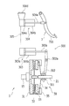
- FIG. 3 is a cross-sectional view showing an example of the configuration of the clutch 3 mounted on the vehicle shown in FIG.
- the clutch 3 includes a friction clutch 30 (also simply referred to as “clutch 30”) and a clutch operating mechanism 300 that operates the friction clutch 30 in response to a depression operation of the clutch pedal 7.
- the friction clutch 30 is configured as a dry single-plate friction clutch, and is provided between the crankshaft 15 and the input shaft 21 of the manual transmission 2. Note that a configuration other than the dry single plate type may be adopted as the configuration of the friction clutch 30.
- the friction clutch 30 includes a flywheel 31, a clutch disk 32, a pressure plate 33, a diaphragm spring 34, and a clutch cover 35.
- a flywheel 31 and a clutch cover 35 are attached to a crankshaft 15 as an input shaft of the friction clutch 30 so as to be integrally rotatable.
- a clutch disk 32 is spline-fitted to the input shaft 21 of the manual transmission 2 that is the output shaft of the friction clutch 30. For this reason, the clutch disk 32 can slide along the axial direction (left-right direction in FIG. 3) while rotating integrally with the input shaft 21.
- a pressure plate 33 is disposed between the clutch disk 32 and the clutch cover 35. The pressure plate 33 is urged toward the flywheel 31 by the outer peripheral portion of the diaphragm spring 34.
- the clutch operating mechanism 300 includes a release bearing 301, a release fork 302, a clutch release cylinder 303, a clutch master cylinder 304, and the like.
- the release bearing 301 is slidably mounted on the input shaft 21 along the axial direction.
- a release fork 302 is rotatably supported by a shaft 302a, and one end thereof (the lower end in FIG. 3) is in contact with the release bearing 301.
- One end (the right end in FIG. 3) of the rod 303a of the clutch release cylinder 303 is connected to the other end (the upper end in FIG. 3) of the release fork 302.
- the clutch release cylinder 303 has a structure in which a piston 303c and the like are incorporated in a cylinder body 303b. The other end of the rod 303a (the left end in FIG. 3) is connected to the piston 303c.
- the clutch release cylinder 303 is connected to the clutch master cylinder 304 via a hydraulic pipe 305.
- the clutch master cylinder 304 has a configuration in which a piston 304c and the like are incorporated in a cylinder body 304b.
- One end (the left end in FIG. 3) of the rod 304a is connected to the piston 304c.
- the other end of the rod 304a (the right end in FIG. 3) is connected to an intermediate portion of the pedal lever 711 of the clutch pedal 7.
- a reserve tank 304d for supplying clutch fluid (oil) as a working fluid into the cylinder body 304b is provided on the upper portion of the cylinder body 304b.
- the clutch master cylinder 304 is adapted to generate hydraulic pressure by the movement of the piston 304c within the cylinder body 304b by receiving an operation force due to the depression of the clutch pedal 7 by the driver.
- the hydraulic pressure generated by the clutch master cylinder 304 is transmitted to the clutch release cylinder 303 by the oil in the hydraulic pipe 305.
- the release fork 302 is operated in accordance with the hydraulic pressure in the clutch release cylinder 303, whereby the friction clutch 30 is engaged and disconnected. Specifically, when the amount of depression of the clutch pedal 7 increases from the state shown in FIG. 3 (clutch engagement state), oil is supplied from the clutch master cylinder 304 to the clutch release cylinder 303, and the inside of the clutch release cylinder 303 The hydraulic pressure increases. Then, the piston 303c and the rod 303a are moved in the right direction in FIG. 3, the release fork 302 is rotated around the shaft 302a (in FIG. 3, the clockwise direction), and the release bearing 301 is moved to the flywheel 31. Pushed to the side.
- the central portion of the diaphragm spring 34 is elastically deformed in the same direction. Accordingly, the urging force of the diaphragm spring 34 against the pressure plate 33 is weakened. For this reason, it will be in the half-clutch state to which the pressure plate 33, the clutch disc 32, and the flywheel 31 are engaged while sliding.
- the manual transmission 2 shown in FIG. 1 is, for example, a known synchronous mesh type manual transmission (for example, 6 forward speeds and 1 reverse speed). As shown in FIG. 1, the manual transmission 2 is connected to the crankshaft 15 of the engine 1 through the clutch 3, and when the clutch 3 is in the engaged state, The driving force (driving torque) is shifted at a predetermined gear ratio and transmitted to the output shaft (drive shaft) 22.
- driving torque driving torque
- the manual transmission 2 operates to form a gear position corresponding to the shift position selected and operated by the shift lever 501 of the shift device 5 shown in FIG.
- the shift position selected by the shift lever 501 is detected by the shift position sensor 502.
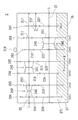
- FIG. 4 is a skeleton diagram showing an example of the manual transmission 2 mounted on the vehicle shown in FIG.
- the manual transmission 2 includes an input shaft 21, an output shaft 22, six sets of forward gears 201 to 206 having different reduction ratios, one set of reverse gears 207, and one-two gears.
- a synchromesh mechanism 24A, a 3-4 shift synchromesh mechanism 24B, a 5-6 shift synchromesh mechanism 24C, a casing 26, and the like are provided.
- the input shaft 21 is connected to the crankshaft 15 of the engine 1 via the clutch 3.
- the output shaft 22 is connected to the drive shaft 41 (see FIG. 1). Further, based on the ratio of the rotational speeds obtained from the output signals of the input shaft rotational speed sensor 218 and the output shaft rotational speed sensor 411 (output shaft rotational speed No / input shaft rotational speed Ni) shown in FIG. The gear stage can be determined.
- the forward gears 201 to 206 are configured by combining drive gears 211 to 216 externally mounted on the input shaft 21 side and driven gears 221 to 226 externally mounted on the output shaft 22 side.
- the drive gears 211 to 216 and the driven gears 221 to 226 are meshed with each other.
- the first-speed and second-speed drive gears 211 and 212 are attached so as to rotate integrally with the input shaft 21, but the third to sixth-speed drive gears 213 to 216 are attached to the input shaft 21 with bearings (for example, It is attached to be relatively rotatable via a cage and roller.
- the 1st and 2nd driven gears 221 and 222 are attached to the output shaft 22 through bearings (eg, cage and rollers) so as to be relatively rotatable, but the 3rd to 6th driven gears 223 to 226 are output. It is attached so as to rotate integrally with the shaft 22.
- the reverse gear stage 207 includes a reverse drive gear 217, a reverse driven gear 227, a reverse idler gear 237, and the like.
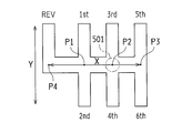
- FIG. 5 is a plan view showing an example of a shift pattern (shift gate shape) of the shift gate that guides the movement of the shift lever 501 of the shift device 5 shown in FIG.
- FIG. 5 shows an outline of a shift pattern of the manual transmission 2 having six forward speeds and one reverse speed.
- the shift lever 501 is configured to be able to perform a direction selection operation in FIG. 5 and a shift operation in a direction indicated by an arrow Y orthogonal to the selection operation direction.
- the 1st-2nd speed select position P1, the 3rd-4th speed select position P2, the 5th-6th speed select position P3, and the reverse select position P4 are arranged in a line.
- the shift lever 501 can be moved to the first speed position 1st or the second speed position 2nd by a shift operation (operation in the arrow Y direction) at the first speed-2nd speed select position P1.
- the shift lever 501 is operated to the 1st speed position 1st, the sleeve 241 of the 1-2 shift synchromesh mechanism 24A of the manual transmission 2 operates to the 1st speed establishment side (right side in FIG. 4) and the 1st speed stage Is established.
- the shift lever 501 when the shift lever 501 is operated to the 2nd speed position 2nd, the sleeve 241 of the 1-2 speed synchromesh mechanism 24A is operated to the 2nd speed establishment side (left side in FIG. 4) to establish the 2nd speed stage. .
- the shift lever 501 can be moved to the third gear position 3rd or the fourth gear position 4th by a shift operation at the third gear-4th gear select position P2.
- the shift lever 501 is operated to the 3rd speed position 3rd
- the sleeve 241 of the 3-4 shift synchromesh mechanism 24B of the manual transmission 2 operates to the 3rd speed establishment side (the right side in FIG. 4) and the 3rd speed stage Is established.
- the shift lever 501 is operated to the 4th speed position 4th
- the sleeve 241 of the 3-4 shift synchromesh mechanism 24B is operated to the 4th speed establishment side (left side in FIG. 4) to establish the 4th speed stage. .
- the shift lever 501 can be moved to the 5th speed position 5th or the 6th speed position 6th by a shift operation at the 5th-6th speed select position P3.
- the sleeve 241 of the 5-6 shift synchromesh mechanism 24C of the manual transmission 2 operates to the 5th speed establishment side (right side in FIG. 4), and the 5th speed stage Is established.
- the sleeve 241 of the 5-6 shift synchromesh mechanism 24C operates to the 6th speed establishment side (left side in FIG. 4) to establish the 6th speed stage. .
- the shift lever 501 can be moved to the reverse position REV by a shift operation at the reverse select position P4.
- the synchromesh mechanisms 24A, 24B, 24C of the manual transmission 2 are in the neutral state (neutral state), and the reverse idler gear 237 of the manual transmission 2 is operated. As a result, the reverse gear is established.
- the 3rd-4th gear select position P2 is the neutral position.
- the synchromesh mechanisms 24A, 24B, 24C of the manual transmission 2 are in the neutral state, and the manual transmission 2 is torqued between the input shaft 21 and the output shaft 22. Neutral state with no transmission.
- the ECU (Electronic Control Unit) 8 (8A) includes a CPU (Central Processing Unit), a ROM (Read Only Memory), a RAM (Random Access Memory), a backup RAM, and the like.
- CPU Central Processing Unit
- ROM Read Only Memory
- RAM Random Access Memory
- the ROM stores various control programs.
- the CPU reads various control programs stored in the ROM and executes various processes.
- the RAM is a memory that temporarily stores calculation results and the like in the CPU, and the backup RAM is a non-volatile memory that stores data and the like to be saved when the engine 1 is stopped.
- the ECU 8 (8A) includes an engine speed sensor 124, an input shaft speed sensor 218, an output shaft speed sensor 411, an axle speed sensor 431, a neutral sensor 251, a shift stroke sensor 252, a select stroke sensor 253, and a shift.
- a position sensor 502, an accelerator opening sensor 61, a clutch stroke sensor 71 (see FIG. 1), and the like are connected to be communicable (see FIG. 11).
- an injector 102, an igniter 104 of a spark plug 103, a throttle motor 106 of a throttle valve 105, and the like are connected to the ECU 8 (8A) as control targets. Then, the ECU 8 (8A) executes various controls of the engine 1 including the fuel injection control of the injector 102, the ignition timing control of the spark plug 103, the drive control of the throttle motor 106, and the like based on the outputs of the various sensors ( (See FIG. 11).
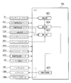
- FIG. 6 is a functional configuration diagram illustrating an example of a functional configuration of the ECU 8 according to the first embodiment of the present invention.
- the ECU 8 functions as a detection unit 811, a position storage unit 812, a prohibition unit 813, a learning unit 814, a rotation synchronization unit 815, and the like by reading and executing a control program stored in a ROM or the like.
- the detection unit 811, the position storage unit 812, the prohibition unit 813, the learning unit 814, and the rotation synchronization unit 815 correspond to a part of the shift control device according to the present invention.
- the detection unit 811 is a functional unit that detects a clutch stroke via the clutch stroke sensor 71.
- the detection unit 811 corresponds to the detection means described in the claims.
- the position storage unit 812 is a functional unit that stores a shift operation position St0 that is a position where the shift operation is performed when the clutch 3 is in a disconnected state.
- the shift operation position St0 is written into the position storage unit 812 by the learning unit 814 and read from the position storage unit 812 by the rotation synchronization unit 815.
- the position storage unit 812 corresponds to a part of the setting learning unit described in the claims.
- the prohibition unit 813 is a functional unit that prohibits the learning operation of the shift operation position St0 from the learning unit 814 when a preset prohibition condition is satisfied.
- the prohibition unit 813 corresponds to prohibition means described in the claims.
- the prohibition conditions are the following prohibition condition A and prohibition condition B.
- Prohibited condition A The manual transmission 2 is in the neutral (N) position.
- Prohibition condition B The rotational speed Ne of the engine 1 matches the input shaft rotational speed Ni of the manual transmission 2.
- the prohibition unit 813 prohibits the learning operation of the shift operation position St0 from the learning unit 814 when at least one of the prohibition condition A and the prohibition condition B is satisfied. Whether or not the prohibition condition A is satisfied is determined based on the output of the neutral sensor 251, for example.
- Whether or not the prohibition condition B is satisfied is determined based on, for example, the output of the engine rotation speed sensor 124 and the output of the input shaft rotation speed sensor 218. More specifically, the prohibition unit 813 determines that the prohibition condition B is satisfied when the following expression (1) is satisfied.
- the rotation speed difference threshold value ⁇ N0 is set to a sufficiently small value (for example, 5 rpm) as compared with the rotation speed Ne of the engine 1.
- double clutch operation means that the clutch 3 is disengaged, the shift position is set to neutral (N), the clutch 3 is engaged, the accelerator pedal 6 is depressed, and the engine rotational speed Ne is increased. This is an operation of shifting down the clutch 3 with the clutch 3 disengaged and engaging the clutch 3 again.
- the clutch 3 is engaged in order to increase the input shaft rotational speed Ni of the manual transmission 2 in the “double clutch operation”
- an operation for bringing the clutch 3 into an engaged state is performed.
- the shift operation position does not become a constant value (that is, the shift operation position St0 cannot be obtained).
- clutchless speed change means that the engine rotational speed Ne is substantially matched with the input shaft rotational speed Ni without disengaging the clutch 3 (with the clutch 3 engaged), and the shift position. Is a gear shifting operation for putting the gear from the neutral position (N) into the travel position (for example, the third gear position 3rd). That is, at the time of “clutchless speed change”, although the speed change operation is performed, the clutch 3 remains engaged at the time of speed change, so the speed change operation position St0 cannot be learned in the first place.
- the prohibiting unit 813 determines whether or not the prohibiting condition A is satisfied based on the output of the neutral sensor 251 . However, the prohibiting unit 813 replaces the output of the neutral sensor 251 with each other. Alternatively (or in addition), it may be determined whether or not the prohibition condition A is satisfied based on the output of the shift position sensor 502.
- the prohibiting unit 813 prohibits the learning operation of the shift operation position St0 when at least one of the prohibiting condition A and the prohibiting condition B is satisfied.
- the learning operation of the shift operation position St0 may be prohibited when the prohibition condition B is satisfied.
- the clutch stroke St detected by the detection unit 811 is used to perform a shift operation while the clutch 3 is in a disconnected state.
- This is a functional unit that writes in the position storage unit 812 as the shift operation position St0 that is a position (that is, executes learning of the shift operation position St0).
- the learning unit 814 corresponds to setting learning means described in the claims.
- Learning condition A The change amount ⁇ St per unit time ⁇ T of the clutch stroke St is equal to or less than a first change amount threshold value ⁇ St0 set in advance.
- Learning condition B a second change amount threshold value ( ⁇ Ni / ⁇ V) in which a change amount ( ⁇ Ni / ⁇ V) per unit time ⁇ T of a quotient (Ni / V) obtained by dividing the input shaft rotation speed Ni of the manual transmission 2 by the vehicle speed V is preset ( ⁇ Ni0 / ⁇ V0) or more.
- the shift operation position St0 is learned when the change amount ⁇ St per unit time ⁇ T of the clutch stroke St is equal to or less than a preset first change amount threshold value ⁇ St0.
- the change amount threshold value ⁇ St0 is set to an appropriate value, for example, when the amount of depression of the clutch pedal 7 has hardly changed, the shift operation position St0 can be learned (see FIG. 7A). ). That is, the driver does not change the amount of depression of the clutch pedal 7 in order to perform the gear shifting operation when the clutch stroke St reaches the gear shifting operation position St0. Therefore, when the amount of depression of the clutch pedal 7 has hardly changed, an appropriate value of the shift operation position St0 can be learned by executing learning of the shift operation position St0.
- a change amount ( ⁇ Ni / ⁇ V) per unit time ⁇ T of a quotient (Ni / V) obtained by dividing the input shaft rotational speed Ni of the manual transmission 2 by the vehicle speed V is set in advance.
- Learning of the shift operation position St0 is executed when the change amount threshold ( ⁇ Ni0 / ⁇ V0) is equal to or greater.
- a change amount ( ⁇ Ni / ⁇ V) per unit time ⁇ T of a quotient (Ni / V) obtained by dividing the input shaft rotation speed Ni of the manual transmission 2 by the vehicle speed V. ) Increases (see FIG. 7B). Therefore, the proper shift operation position St0 can be learned by setting the second change amount threshold value ( ⁇ Ni0 / ⁇ V0) to an appropriate value.
- the learning unit 814 performs learning of the shift operation position St0 when the learning condition A and the learning condition B are satisfied.
- the learning unit 814 includes the learning condition A and the learning condition.
- learning of the shift operation position St0 may be performed when the following learning condition C is satisfied.
- Learning condition C a third change amount threshold value ( ⁇ Ne0 / ⁇ V0) in which a change amount ( ⁇ Ne / ⁇ V) per unit time ⁇ T of a quotient (Ne / V) obtained by dividing the rotational speed Ne of the engine 1 by the vehicle speed V is preset. That's it.
- a change amount ( ⁇ Ne / ⁇ V) per unit time ⁇ T of a quotient (Ne / V) obtained by dividing the rotational speed Ne of the engine 1 by the vehicle speed V is a preset third change amount threshold value ( When it is equal to or greater than ( ⁇ Ne0 / ⁇ V0), the shift operation position St0 is learned. Further, at the speed change operation position St0, when the speed change operation is performed, the amount of change ( ⁇ Ne / ⁇ V) per unit time ⁇ T of the quotient (Ne / V) obtained by dividing the rotational speed Ne of the engine 1 by the vehicle speed V increases. (See FIG. 7 (a)). Therefore, the appropriate shift operation position St0 can be learned by setting the third change amount threshold ( ⁇ Ne0 / ⁇ V0) to an appropriate value.
- the learning unit 814 performs learning of the shift operation position St0 when the learning condition A and the learning condition B are satisfied.
- the learning unit 814 includes the learning condition A and the learning condition.
- learning of the shift operation position St0 may be performed when the following learning condition D is satisfied.
- Learning condition D Since the absolute value
- of the change amount ⁇ Ni per unit time ⁇ T of the input shaft rotational speed Ni of the manual transmission 2 is less than a preset fourth change amount threshold value ⁇ Ni0.
- Learning of the shift operation position St0 is executed when the change amount threshold value ⁇ Ni0 is greater than or equal to a preset fifth change amount threshold value ⁇ Ni1.
- of the change amount ⁇ Ni per unit time ⁇ T of the input shaft rotational speed Ni of the manual transmission 2 is increased by performing the shift operation (see FIG. 7B). ). Therefore, learning of the proper shift operation position St0 can be executed by setting the fourth change amount threshold value ⁇ Ni0 and the fifth change amount threshold value ⁇ Ni1 to appropriate values.
- the rotation synchronization unit 815 is a functional unit that executes rotation synchronization control that is control for synchronizing the rotation speed Ne of the engine 1 with the input shaft rotation speed Ni of the manual transmission 2 at the time of shifting.
- the rotation synchronization unit 815 corresponds to the rotation synchronization means described in the claims.
- the rotation synchronizing unit 815 causes the detecting unit 811 to advance the clutch stroke St from the shift operation position St0 to the engaging side in advance.
- the rotation synchronization control is started (see FIG. 7C).
- the rotation synchronization unit 815 detects the clutch detected by the detection unit 811 when the clutch 3 is switched from the disengaged state to the engaged state.
- the rotation synchronization control is terminated (see FIG. 7C).
- the rotation synchronization unit 815 indicates that the speed is changing, for example, the rotational speed Ne of the engine 1 does not coincide with the input shaft rotational speed Ni of the manual transmission 2 (that is, the clutch 3 is not engaged).
- the determination is made according to whether or not the following expression (2) is satisfied.
- the rotation speed difference threshold value ⁇ N0 is set to a sufficiently small value (for example, 5 rpm) as compared with the rotation speed Ne of the engine 1.
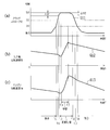
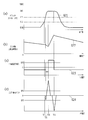
- FIG. 7 is a timing chart showing an example of the operation of the ECU 8 shown in FIG.
- FIG. 7A is a graph G11 showing a change in the clutch stroke St.
- the upper side of the vertical axis is the cut side, and the lower side is the engagement side.
- the engagement start position St1 which is the clutch stroke St at which engagement is started
- the complete engagement position which is the clutch stroke St at which the clutch 3 is completely engaged (the clutch 3 is not slipped).
- FIG. 7B is a graph G12 showing a change in the input shaft rotational speed Ni of the manual transmission 2.
- FIG. 7C is a graph G13 showing a change in the rotational speed Ne of the engine 1.
- the clutch stroke St is on the engagement side with respect to the complete engagement position St2, so the clutch 3 is in the engaged state, and as shown in the graph G12 and the graph G13, the engine 1
- the rotational speed Ne of the manual transmission 2 coincides with the input shaft rotational speed Ni of the manual transmission 2.
- the clutch stroke St reaches the complete engagement position St2.
- the clutch stroke St reaches the engagement start position St1, and as shown in the graph G12, the manual transmission 2 is in the neutral (N) position.
- the deceleration rate of the input shaft rotational speed Ni of the manual transmission 2 is increasing.
- the clutch stroke St reaches the position of the first stroke ⁇ St1 from the gear shift operation position St0 to the engagement side. Is synchronized with the input shaft rotational speed Ni of the manual transmission 2.
- a speed change operation here, a downshift operation from the third speed 3rd to the second speed 2nd
- the input shaft rotational speed Ni of the manual transmission 2 suddenly increases. It is increasing.
- the speed change operation here, the downshift operation from the third speed 3rd to the second speed 2nd
- the input shaft rotational speed Ni of the manual transmission 2 starts to decrease as shown in the graph G12. Yes.
- the clutch stroke St is fixed at the shift operation position St0, and neither the prohibition condition A nor the prohibition condition B is satisfied.
- learning of the shift operation position St0 is performed by the learning unit 814.
- the clutch stroke St reaches the position of the second stroke ⁇ St2 from the shift operation position St0 toward the engagement side.
- the rotation synchronization control which is a control for synchronizing Ne with the input shaft rotation speed Ni of the manual transmission 2, is ended.
- the clutch stroke St reaches the engagement start position St1, as shown in the graph G11.
- the clutch stroke St reaches the complete engagement position S2, as shown in the graph G11.
- FIG. 8 is a flowchart showing an example of the learning operation of the ECU 8 shown in FIG.
- the prohibition unit 813 satisfies a condition that the rotational speed Ne of the engine 1 matches the input shaft rotational speed Ni of the manual transmission 2 (prohibition condition B:
- a determination is made (step S101). If YES in step S101, the process is in a standby state. If NO in step S101, the process proceeds to step S103.
- step S103 determines whether or not the condition that the manual transmission 2 is in the neutral (N) position (prohibition condition A) is satisfied. If YES in step S103, the process is returned. If NO in step S103, the process proceeds to step S105.
- the learning unit 814 determines whether or not the condition (learning condition A) that the change amount ⁇ St per unit time ⁇ T of the clutch stroke St is equal to or less than a preset first change amount threshold value ⁇ St0 is satisfied. (Step S105). If NO in step S105, the process is returned. If YES in step S105, the process proceeds to step S107.
- the learning unit 814 performs a second change in which a change amount ( ⁇ Ni / ⁇ V) per unit time ⁇ T of a quotient (Ni / V) obtained by dividing the input shaft rotation speed Ni of the manual transmission 2 by the vehicle speed V is set in advance. It is determined whether or not a condition (learning condition B) that is equal to or greater than the quantity threshold ( ⁇ Ni0 / ⁇ V0) is satisfied (step S107). If NO in step S107, the process is returned. If YES in step S107, the process proceeds to step S109.
- step S109 Processing then returns.
- the learning unit 814 satisfies the learning condition A (condition that the amount of depression of the clutch pedal 7 is substantially fixed) and the learning condition B (condition that the shift operation is being performed). Since learning of the shift operation position St0 is executed at the same time, it is possible to execute learning of an appropriate shift operation position St0 (see FIG. 7A).
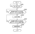
- FIG. 9 is a flowchart showing an example of the operation of the rotation synchronization control by the ECU shown in FIG.
- the following processing is all executed by the rotation synchronization unit 815.
- Step S201 it is determined whether or not the condition that the rotational speed Ne of the engine 1 does not coincide with the input shaft rotational speed Ni of the manual transmission 2 (condition that the clutch 3 is not engaged) is satisfied. If NO in step S201, the process is in a standby state. If YES in step S201, the process proceeds to step S203.
- step S203 when the clutch 3 is switched from the engaged state to the disconnected state, it is determined whether or not the clutch stroke St has reached the position of the first stroke ⁇ St1 from the shift operation position St0 toward the engagement side (step S203). . If NO in step S203, the process is in a standby state. If YES in step S203, the process proceeds to step S205. Next, rotation synchronization control, which is control for synchronizing the rotation speed Ne of the engine 1 with the input shaft rotation speed Ni of the manual transmission 2, is started (step S205).
- step S207 when the speed change operation is performed and the clutch 3 is switched from the disengaged state to the engaged state, whether or not the clutch stroke St has reached the position of the second stroke ⁇ St2 from the speed change operation position St0 toward the engagement side. Is determined (step S207). If NO in step S207, the process returns to step S205, and the rotation synchronization control is continuously executed. If YES in step S207, the process proceeds to step S209. Then, the rotation synchronization control that is the control for synchronizing the rotation speed Ne of the engine 1 with the input shaft rotation speed Ni of the manual transmission 2 is ended (step S209), and the processing is ended.
- the clutch stroke St is related to the shifting operation position St0 that is a position where the clutch 3 is disconnected and the shifting operation is performed. Since the rotation synchronization control for synchronizing the rotation speed Ne of the engine 1 with the input shaft rotation speed Ni of the manual transmission 2 is started when the position of the first stroke ⁇ St1 set in advance to the side is reached. By appropriately setting the position St0 and the first stroke ⁇ St1, it is possible to reliably avoid a shock when the clutch 3 is engaged.
- FIG. 10 is a timing chart showing an example of another embodiment of the learning conditions of the learning unit 814 shown in FIG.
- the learning unit 814 may learn the shift operation position St0 when the learning condition A and the following learning condition E are satisfied instead of (or in addition to) the learning condition B.
- the twice differential value ND2 of the input shaft rotational speed Ni of the manual transmission 2 is equal to or more than a preset positive first differential threshold DF1, and the input shaft rotational speed Ni of the manual transmission 2 is one time.
- the differential value ND becomes equal to or higher than the preset positive second differential threshold value DF2
- the second differential value ND2 of the input shaft rotational speed Ni of the manual transmission 2 is equal to or lower than the preset negative third differential threshold value DF3. That became.
- FIG. 10 (a) is the same graph as FIG. 7 (a), and is a graph G21 showing the change of the clutch stroke St.
- the upper side of the vertical axis is the cutting side, and the lower side is the engaging side.
- the vertical axis indicates an engagement start position St1 that is a clutch stroke St at which engagement is started, and a shift operation position St0 that is a position where the clutch 3 is disengaged and a shift operation is performed.
- FIG. 10B is the same graph as FIG. 7B, and is a graph G22 showing a change in the input shaft rotational speed Ni of the manual transmission 2.
- FIG. 10C is a graph G23 showing a change in the first derivative value ND1 of the input shaft rotational speed Ni of the manual transmission 2.
- FIG. 10 (d) is a graph G ⁇ b> 24 showing a change in the twice differential value ND ⁇ b> 2 of the input shaft rotational speed Ni of the manual transmission 2.
- the clutch stroke St reaches the engagement start position St1
- the manual transmission 2 is in the neutral (N) position.
- the deceleration rate of the input shaft rotational speed Ni of the manual transmission 2 is increasing.
- the one-time differential value ND1 of the input shaft rotational speed Ni of the manual transmission 2 decreases as shown in the graph G23.
- the double differential value ND2 of the input shaft rotational speed Ni of the manual transmission 2 has a low impulse waveform on the minus side.
- a speed change operation (for example, a shift down operation from the third speed 3rd to the second speed 2nd) is started, and the input shaft rotational speed Ni of the manual transmission 2 is increased as shown in the graph G22. . Therefore, at time T23, as shown in the graph G23, the one-time differential value ND1 of the input shaft rotational speed Ni of the manual transmission 2 increases stepwise to a positive value, and as shown in the graph G24, The two-time differential value ND2 of the input shaft rotational speed Ni of the manual transmission 2 has a high impulse waveform on the plus side.
- the two-time differential value ND2 of the input shaft rotational speed Ni of the manual transmission 2 becomes equal to or more than the positive first differential threshold DF1, and as shown in the graph G23, the manual differential The one-time differential value ND of the input shaft rotational speed Ni of the transmission 2 is equal to or greater than a preset second positive differential threshold DF2.
- the speed change operation (for example, the downshift operation from the third speed 3rd to the second speed 2nd) is finished, and the input shaft rotational speed Ni of the manual transmission 2 starts to decrease as shown in the graph G22. . Therefore, at time T24, as shown in the graph G23, the one-time differential value ND1 of the input shaft rotational speed Ni of the manual transmission 2 is decreased to a negative value in a stepwise manner, and as shown in the graph G24, The twice differential value ND2 of the input shaft rotational speed Ni of the manual transmission 2 has a high impulse waveform on the negative side. Therefore, at time T24, as shown in the graph G24, the two-time differential value ND2 of the input shaft rotational speed Ni of the manual transmission 2 becomes equal to or less than the negative third differential threshold DF3, and the learning condition E is satisfied.
- the speed change operation for example, the downshift operation from the third speed 3rd to the second speed 2nd
- FIG. 11 is a functional configuration diagram showing an example of a functional configuration of the ECU 8A according to the second embodiment of the present invention.
- the ECU 8A functions as a detection unit 821, a prohibition unit 823, a setting unit 824, a rotation synchronization unit 825, and the like by reading and executing a control program stored in a ROM or the like.
- the detection unit 821, the prohibition unit 823, the setting unit 824, and the rotation synchronization unit 825 correspond to a part of the shift control device according to the present invention.
- the ECU 8A is different from the ECU 8 shown in FIG. 6 in that a setting unit 824 is provided instead of the position storage unit 812 and the learning unit 814. Since the detection unit 821, the prohibition unit 823, and the rotation synchronization unit 825 have substantially the same functions as the detection unit 811, the prohibition unit 813, and the rotation synchronization unit 815 of the ECU 8 illustrated in FIG. Different functions will be described, and descriptions of the same functions will be omitted.
- the prohibition unit 823 is a functional unit that prohibits the setting operation of the shift operation position St0 with respect to the setting unit 824 when at least one of the prohibition condition A and the prohibition condition B described with reference to FIG. 6 is satisfied. It is.
- the prohibition unit 823 corresponds to prohibition means described in the claims.
- the prohibiting unit 823 prohibits the setting operation of the shift operation position St0 when at least one of the prohibiting condition A and the prohibiting condition B is satisfied.
- the setting operation of the shift operation position St0 may be prohibited when the prohibition condition B is satisfied.
- the setting unit 824 is a functional unit that sets the clutch stroke St detected by the detection unit 821 when the learning condition A and the learning condition B described with reference to FIG. 6 are satisfied as the shift operation position St0.
- the setting unit 824 corresponds to setting learning means described in the claims.
- the setting unit 824 executes the setting of the shift operation position St0 when the learning condition A and the learning condition B are satisfied.
- the shift operation position St0 may be set when the learning condition C described with reference to FIG. 6 is satisfied.
- the setting unit 824 satisfies the learning condition A and the learning condition D described with reference to FIG. 6 instead of (or in addition to) the learning condition B
- the shift operation position St0 is learned. Form may be sufficient.
- the setting unit 824 satisfies the learning condition A and the learning condition E described with reference to FIG. 10 instead of (or in addition to) the learning condition B
- the shift operation position St0 is learned. Form may be sufficient.
- the rotation synchronization unit 825 is a functional unit that executes rotation synchronization control, which is control for synchronizing the rotation speed Ne of the engine 1 with the input shaft rotation speed Ni of the manual transmission 2 at the time of shifting.
- the rotation synchronization unit 825 corresponds to the rotation synchronization means described in the claims.
- the rotation synchronization unit 825 detects the clutch detected by the detection unit 821 when the clutch 3 is switched from the disconnected state to the engaged state.
- the rotation synchronization control is terminated.
- the learning unit 814 illustrated in FIG. 6 performs learning of the shift operation position St0 that is a position where the clutch 3 is disengaged and the shift operation is performed, whereas the setting unit 824 sets the shift operation position St0. Therefore, every time a shift is performed, an appropriate operation is performed based on the operation performed at that time and the state of the vehicle (for example, the temperature of the clutch disk 32 (see FIG. 3) of the clutch 3 and the degree of wear).
- the shift operation position St0 is set. Accordingly, even when the shift operation position St0 is different each time a shift is performed, the rotation synchronization control can be executed at an appropriate timing.
- FIG. 12 is a flowchart showing an example of the learning operation of the ECU 8A shown in FIG. First, whether or not the prohibition unit 823 satisfies the condition that the rotational speed Ne of the engine 1 matches the input shaft rotational speed Ni of the manual transmission 2 (prohibition condition B:
- a determination is made (step S301). If YES in step S301, the process enters a standby state. If NO in step S301, the process proceeds to step S303.
- step S303 determines whether or not the condition that the manual transmission 2 is in the neutral (N) position (prohibition condition A) is satisfied. If YES in step S303, the process is returned. If NO in step S303, the process proceeds to step S305.
- the setting unit 824 determines whether or not the condition (learning condition A) that the change amount ⁇ St per unit time ⁇ T of the clutch stroke St is equal to or less than a preset first change amount threshold value ⁇ St0 is satisfied. (Step S305). If NO in step S305, the process is returned. If YES in step S305, the process proceeds to step S307.
- step S307 a second change in which a change amount ( ⁇ Ni / ⁇ V) per unit time ⁇ T of a quotient (Ni / V) obtained by dividing the input shaft rotation speed Ni of the manual transmission 2 by the vehicle speed V is set by the setting unit 824 in advance. It is determined whether or not the condition (learning condition B) that is equal to or greater than the quantity threshold ( ⁇ Ni0 / ⁇ V0) is satisfied (step S307). If NO in step S307, the process is returned. If YES in step S307, the process proceeds to step S309. Then, the clutch stroke St detected by the detection unit 811 is set by the setting unit 824 as a shift operation position St0 that is a position where the clutch 3 is disengaged and a shift operation is performed (step S309).
- the rotation synchronization unit 825 starts rotation synchronization control which is control for synchronizing the rotation speed Ne of the engine 1 with the input shaft rotation speed Ni of the manual transmission 2 (step S311).
- a speed change operation is performed, and the rotation synchronization unit 825 determines whether or not the clutch stroke St has reached the position of the second stroke ⁇ St2 from the speed change operation position St0 toward the engagement side (step S313). If NO in step S313, the process returns to step S311. If YES in step S313, the process proceeds to step S315.
- the rotation synchronization unit 825 ends the rotation synchronization control that is the control for synchronizing the rotation speed Ne of the engine 1 with the input shaft rotation speed Ni of the manual transmission 2 (step S315), and the process is returned.
- the shift operation position St0 is set, and the rotational speed Ne of the engine 1 is synchronized with the input shaft rotational speed Ni of the manual transmission 2. Since the rotation synchronization control to be started is started, a shock at the time of engaging the clutch 3 can be surely avoided.
- the ECU 8 functions as the detection unit 811, the position storage unit 812, the prohibition unit 813, the learning unit 814, and the rotation synchronization unit 815 has been described, but the detection unit 811 and the position storage unit 812 are described.
- at least one of the prohibition unit 813, the learning unit 814, and the rotation synchronization unit 815 may be configured by hardware such as an electronic circuit.
- the case where the ECU 8A functions as the detection unit 821, the prohibition unit 823, the setting unit 824, and the rotation synchronization unit 825 has been described. However, the detection unit 821, the prohibition unit 823, and the setting unit are described. At least one of 824 and the rotation synchronization unit 825 may be configured by hardware such as an electronic circuit.
- the ECU 8 learns the shift operation position St0.
- the ECU 8 learns and sets the shift operation position St0. But you can.
- the ECU 8 performs learning and setting of the shift operation position St0 when the learning condition A and the learning condition B are satisfied, and when the learning condition A and the learning condition B are not satisfied, the shift operation is performed.
- the shift operation position St0 stored in the position storage unit 812 may be used.
- the ECU 8 (learning unit 814) writes the shift operation position St0 in the position storage unit 812 when the learning condition A and the learning condition B are satisfied has been described, but the ECU 8 (learning unit 814).
- the learning may be performed by other methods.
- the ECU 8 (learning unit 814) may learn by averaging the shift operation position St0 obtained in the past travel using the following equation (3). St0 ⁇ (St0 (N) + St (N ⁇ 1) ⁇ (N ⁇ 1)) / N (3)
- the shift operation position St0 (N) is a learned value of the Nth shift operation position St0. In this case, a more appropriate shift operation position St0 can be obtained.
- operator of the vehicle is one person (fixed)
- operator of a vehicle is two or more persons (two or more drivers
- the rotation synchronization control can be performed by reflecting the driving characteristics of each driver.
- the driver may be identified based on the position of the driver seat or the like, or the driver may input identification information or the like given to himself / herself.
- the internal combustion engine is the gasoline engine 1
- the internal combustion engine may be another type of internal combustion engine (for example, a diesel engine or the like).
- the present invention relates to a vehicle equipped with an engine, a manual transmission, and a clutch provided between the engine and the manual transmission and configured to be able to switch between a disconnected state and a connected state.
- the present invention can be used for a shift control device that stops the engine when an operation for instructing to stop the engine is performed during traveling.
Landscapes
- Engineering & Computer Science (AREA)
- General Engineering & Computer Science (AREA)
- Mechanical Engineering (AREA)
- Control Of Vehicle Engines Or Engines For Specific Uses (AREA)
- Control Of Transmission Device (AREA)
- Control Of Driving Devices And Active Controlling Of Vehicle (AREA)
Abstract
変速制御装置(ECU8)は、機能的に、クラッチストロークセンサ71を介してクラッチストロークStを検出する検出部811と、エンジン1の回転速度Neを手動変速機2の入力軸回転速度Niに同期させる回転同期制御を実行する回転同期部815と、を備え、クラッチ3が係合状態から切断状態へ切り換えられる際に、検出部811によってクラッチストロークStが、クラッチ3が切断状態であって変速操作が行われる位置である変速操作位置St0より係合側へ予め設定された第1ストロークΔSt1の位置に到達したことが検出されたときに、回転同期部815が前記回転同期制御を開始する。このようにして、クラッチストロークStが適正な位置で前記回転同期制御が開始されるため、クラッチ3締結時のショックを確実に回避することができる。
Description
本発明は、内燃機関と、手動変速機と、前記内燃機関と前記手動変速機との間に介設され、クラッチストロークを変更することによって係合状態と切断状態とを切り換え可能に構成されたクラッチと、を備える車両の変速制御装置に関する。
従来、エンジン(「内燃機関」に相当する。)と手動変速機との間に介設され、クラッチストロークを変更することにより係合状態と切断状態とを切り換えることによって、エンジンと変速機との間のトルクの伝達と遮断とを切り換えるクラッチが搭載された車両が知られている。また、このような車両において、変速時にエンジンの回転速度を手動変速機の入力軸回転速度に同期させる種々の制御装置、制御方法等が提案されている。
例えば、クラッチペダルの半クラッチ位置でONとなる半クラッチスイッチを設け、変速操作によってエンジン回転速度を、変速後の変速機入力側回転速度に同期させる制御を開始し、クラッチペダルの踏み込み後の戻し操作で、前記半クラッチスイッチがONからOFFに切り換えられたときを、半クラッチ状態と判定して前記回転同期制御を終了させるエンジンの変速時制御装置が開示されている(特許文献1参照)。上記特許文献1に記載のエンジンの変速時制御装置によれば、クラッチ締結時のショックを回避することができると記載されている。
しかしながら、上記特許文献1に記載のエンジンの変速時制御装置では、前記半クラッチスイッチの位置で、エンジン回転速度を、変速後の変速機入力側回転速度に同期させる制御が開始されるが、下記の理由によって、前記半クラッチスイッチの位置を適正な位置に配設することは困難であるため、クラッチ締結時のショックが発生する虞がある。
例えば、クラッチディスクの温度が高い程、クラッチディスクの熱膨張量が大きくなるため、前記半クラッチスイッチの位置を適正な位置に配設することは困難である。また、クラッチディスクの磨耗量が多い程、クラッチディスクの厚みが薄くなるため、前記半クラッチスイッチの位置を適正な位置に配設することは困難である。
本発明は、上記課題に鑑みてなされたものであって、クラッチ締結時のショックを確実に回避することを目的としている。
上記課題を解決するために、本発明に係る変速制御装置は、以下のように構成されている。
すなわち、本発明に係る変速制御装置は、内燃機関と、手動変速機と、前記内燃機関と前記手動変速機との間に介設され、クラッチストロークを変更することによって係合状態と切断状態とを切り換え可能に構成されたクラッチと、を備える車両の変速制御装置であって、前記クラッチストロークを検出する検出手段と、前記内燃機関の回転速度を前記手動変速機の入力軸回転速度に同期させる回転同期制御を実行する回転同期手段と、を備え、前記クラッチが係合状態から切断状態へ切り換えられる際に、前記検出手段によって前記クラッチストロークが、前記クラッチが切断状態であって変速操作が行われる位置である変速操作位置より係合側へ予め設定された第1ストロークの位置に到達したことが検出されたときに、前記回転同期手段が前記回転同期制御を開始することを特徴としている。
かかる構成を備える変速制御装置によれば、前記クラッチが係合状態から切断状態へ切り換えられる際に、前記検出手段によって前記クラッチストロークが、前記クラッチが切断状態であって変速操作が行われる位置である変速操作位置より係合側へ予め設定された第1ストロークの位置に到達したことが検出されたときに、前記回転同期手段が前記回転同期制御が開始されるため、前記変速操作位置及び前記第1ストロークを適正に設定することによって、クラッチ締結時のショックを確実に回避することができる。
また、本発明に係る変速制御装置は、前記クラッチが切断状態から係合状態へ切り換えられる際に、前記検出手段によって前記クラッチストロークが前記変速操作位置より係合側へ予め設定された第2ストロークの位置に到達したことが検出されたときに、前記回転同期手段が前記回転同期制御を終了することが好ましい。
かかる構成を備える変速制御装置によれば、前記クラッチが切断状態から係合状態へ切り換えられる際に、前記クラッチストロークが前記変速操作位置より係合側へ予め設定された第2ストロークの位置に到達したことが検出されたときに、前記内燃機関の回転速度を前記手動変速機の入力軸回転速度に同期させる回転同期制御が終了されるため、前記変速操作位置及び前記第2ストロークを適正な値に設定することによって、前記回転同期制御を適正なタイミングで終了することができる。
また、本発明に係る変速制御装置は、前記クラッチストロークの単位時間当たりの変化量が予め設定された第1変化量閾値以下であるときに前記変速操作位置の設定及び学習の少なくとも一方を実行する設定学習手段を更に備えることが好ましい。
かかる構成を備える変速制御装置によれば、前記クラッチストロークの単位時間当たりの変化量が予め設定された第1変化量閾値以下であるときに前記変速操作位置の設定及び学習の少なくとも一方が実行される。また、例えば、クラッチペダルの踏み込み量が変化していないときには、前記クラッチストロークの単位時間当たりの変化量が殆ど無い。したがって、前記第1変化量閾値を適正な値に設定することによって、前記変速操作位置の設定及び学習を実行することができる。
また、本発明に係る変速制御装置は、前記設定学習手段が、前記手動変速機の入力軸回転速度を車速で除した商の単位時間当たりの変化量が予め設定された第2変化量閾値以上であるときに前記変速操作位置の設定及び学習の少なくとも一方を実行することが好ましい。
かかる構成を備える変速制御装置によれば、前記手動変速機の入力軸回転速度を車速で除した商の単位時間当たりの変化量が予め設定された第2変化量閾値以上であるときに前記変速操作位置の設定及び学習の少なくとも一方が実行される。また、前記変速操作位置では、前記手動変速機の入力軸回転速度を車速で除した商の単位時間当たりの変化量が大きくなる(図6、図11参照)。したがって、前記第2変化量閾値を適正な値に設定することによって、適正な前記変速操作位置の設定及び学習を実行することができる。
また、本発明に係る変速制御装置は、前記設定学習手段が、前記内燃機関の回転速度を車速で除した商の単位時間当たりの変化量が予め設定された第3変化量閾値以上であるときに前記変速操作位置の設定及び学習の少なくとも一方を実行することが好ましい。
かかる構成を備える変速制御装置によれば、前記内燃機関の回転速度を車速で除した商の単位時間当たりの変化量が予め設定された第3変化量閾値以上であるときに前記変速操作位置の設定及び学習の少なくとも一方が実行される。また、前記変速操作位置では、前記内燃機関の回転速度を車速で除した商の単位時間当たりの変化量が大きくなる(図6、図11参照)。したがって、前記第3変化量閾値を適正な値に設定することによって、適正な前記変速操作位置の設定及び学習を実行することができる。
また、本発明に係る変速制御装置は、前記設定学習手段が、前記手動変速機の入力軸回転速度の単位時間当たりの変化量の絶対値が予め設定された第4変化量閾値未満から、前記第4変化量閾値以上であって予め設定された第5変化量閾値以上に変化したときに前記変速操作位置の設定及び学習の少なくとも一方を実行することが好ましい。
かかる構成を備える変速制御装置によれば、前記手動変速機の入力軸回転速度の単位時間当たりの変化量の絶対値が予め設定された第4変化量閾値未満から、前記第4変化量閾値以上であって予め設定された第5変化量閾値以上に変化したときに前記変速操作位置の設定及び学習の少なくとも一方が実行される。また、前記変速操作位置では前記手動変速機の入力軸回転速度の単位時間当たりの変化量が小さい値から急激に大きい値に変化する(図6、図11参照)。したがって、前記第4変化量閾値及び前記第5変化量閾値を適正な値に設定することによって、適正な前記変速操作位置の設定及び学習を実行することができる。
また、本発明に係る変速制御装置は、前記設定学習手段が、前記手動変速機の入力軸回転速度の2回微分値が予め設定された正の第1微分閾値以上となり、且つ、前記手動変速機の入力軸回転速度の1回微分値が予め設定された正の第2微分閾値以上となった後、前記手動変速機の入力軸回転速度の2回微分値が予め設定された負の第3微分閾値以下となったときに前記変速操作位置の設定及び学習の少なくとも一方を実行することが好ましい。
かかる構成を備える変速制御装置によれば、前記手動変速機の入力軸回転速度の2回微分値が予め設定された正の第1微分閾値以上となり、且つ、前記手動変速機の入力軸回転速度の1回微分値が予め設定された正の第2微分閾値以上となった後、前記手動変速機の入力軸回転速度の2回微分値が予め設定された負の第3微分閾値以下となったときに前記変速操作位置の設定及び学習の少なくとも一方が実行されるため、前記第1微分閾値、前記第2微分閾値、及び、前記第3微分閾値を適正な値に設定することによって、適正な前記変速操作位置の設定及び学習を実行することができる(図10参照)。
また、本発明に係る変速制御装置は、前記設定学習手段の設定及び学習の実行を禁止する禁止手段を更に備え、前記禁止手段が、前記手動変速機がニュートラル位置であるときに前記設定学習手段の設定及び学習の実行を禁止することが好ましい。
かかる構成を備える変速制御装置によれば、前記手動変速機がニュートラル位置であるときに前記設定学習手段の設定及び学習の実行が禁止されるため、ダブルクラッチ操作において前記手動変速機の入力軸回転速度を上昇させるためにクラッチを係合する際における、前記設定学習手段の設定及び学習の実行を適正に禁止することができる。
また、本発明に係る変速制御装置は、前記学習手段の学習を禁止する禁止手段を更に備え、前記禁止手段が、前記内燃機関の回転速度が前記手動変速機の入力軸回転速度と略一致しているときに前記設定学習手段の設定及び学習の実行を禁止することが好ましい。
かかる構成を備える変速制御装置によれば、前記内燃機関の回転速度が前記手動変速機の入力軸回転速度と略一致しているときに前記設定学習手段の設定及び学習の実行が禁止されるため、クラッチレス変速時における前記設定学習手段の設定及び学習の実行を適正に禁止することができる。
本発明に係る変速制御装置によれば、前記クラッチが係合状態から切断状態へ切り換えられる際に、前記検出手段によって前記クラッチストロークが、前記クラッチが切断状態であって変速操作が行われる位置である変速操作位置より係合側へ予め設定された第1ストロークの位置に到達したことが検出されたときに、前記回転同期手段が前記回転同期制御が開始されるため、前記変速操作位置及び前記第1ストロークを適正に設定することによって、クラッチ締結時のショックを確実に回避することができる。
以下、本発明の実施形態を図面に基づいて説明する。
-パワートレーン-
図1は、本発明に係る変速制御装置(ECU8、8A)が搭載される車両のパワートレーン及びその制御系統の一例を示す構成図である。本実施形態に係る車両は、FR(フロントエンジン・リアドライブ)型の車両であって、エンジン1、手動変速機(マニュアルトランスミッション:MT)2、クラッチ3、油圧回路4、シフト装置5、アクセルペダル6、クラッチペダル7、ECU8(8A)、及び、表示部9等を備えている。なお、本発明に係る変速制御装置は、ECU8(8A)、及び、後述するクラッチストロークセンサ71等に相当する。
図1は、本発明に係る変速制御装置(ECU8、8A)が搭載される車両のパワートレーン及びその制御系統の一例を示す構成図である。本実施形態に係る車両は、FR(フロントエンジン・リアドライブ)型の車両であって、エンジン1、手動変速機(マニュアルトランスミッション:MT)2、クラッチ3、油圧回路4、シフト装置5、アクセルペダル6、クラッチペダル7、ECU8(8A)、及び、表示部9等を備えている。なお、本発明に係る変速制御装置は、ECU8(8A)、及び、後述するクラッチストロークセンサ71等に相当する。
図1に示すように、エンジン1の出力軸であるクランクシャフト15は、クラッチ3に連結されている。また、クラッチ3が継合状態になると、エンジン1の駆動力(駆動トルク)が、クランクシャフト15、クラッチ3、入力軸21、手動変速機2、出力軸22(図4参照)、ドライブシャフト41、差動歯車装置42、及び、車軸43を介して、駆動輪44へ伝達される。
クランクシャフト15の近傍には、クランクシャフト15の回転速度をエンジン回転速度Neとして検出するエンジン回転速度センサ124が配設されている。また、手動変速機2の入力軸21の近傍には、入力軸21の回転速度を入力軸回転速度Niとして検出する入力軸回転速度センサ218が配設され、手動変速機2の出力軸22(又は、ドライブシャフト41)の近傍には、出力軸22(又は、ドライブシャフト41)の回転速度を出力軸回転速度Noとして検出する出力軸回転速度センサ411が配設されている。更に、車軸43の近傍には、車軸43の回転速度を車軸回転速度Nvとして検出する車軸回転速度センサ431が配設されている。エンジン回転速度センサ124によって検出されたエンジン回転速度Ne、入力軸回転速度センサ218によって検出された入力軸回転速度Ni、出力軸回転速度センサ411によって検出された出力軸回転速度No、及び、車軸回転速度センサ431によって検出された車軸回転速度Nvは、ECU8(8A)へ出力される。
シフト装置5には、シフトレバー501が配設されている。シフトレバー501は、運転者によって把持され、シフトポジションを変更する操作が行われるレバーである。アクセルペダル6には、アクセル開度を検出するアクセル開度センサ61が配設されている。更に、クラッチペダル7には、クラッチストロークを検出するクラッチストロークセンサ71が配設されている。アクセル開度センサ61によって検出されたアクセル開度、及び、クラッチストロークセンサ71によって検出されたクラッチストロークは、ECU8(8A)へ出力される(図6、図11参照)。また、クラッチストロークセンサ71は、本発明に係る変速制御装置の一部に相当する。
また、手動変速機2には、シフト位置を検出するシフトポジションセンサ502、ニュートラル(N)位置であることを検出するニュートラルセンサ251、シフトストロークを検出するシフトストロークセンサ252、及び、セレクトストロークを検出するセレクトストロークセンサ253が配設されている。シフトポジションセンサ502、ニュートラルセンサ251、シフトストロークセンサ252及びセレクトストロークセンサ253の検出結果は、ECU8(8A)へ出力される(図6、図11参照)。
-エンジン-
次に、図2を参照して、本実施形態に係るエンジン1について説明する。図2は、図1に示す車両に搭載されるエンジン1の一例を示す構成図である。エンジン1は、例えば、多気筒ガソリンエンジンであって、燃焼室1aを形成するピストン1b、及び、出力軸であるクランクシャフト15(図1参照)を備えている。ピストン1bは、コネクティングロッド16を介して、クランクシャフト15に連結されている。また、ピストン1bの往復運動は、コネクティングロッド16によって、クランクシャフト15の回転運動へと変換される。
次に、図2を参照して、本実施形態に係るエンジン1について説明する。図2は、図1に示す車両に搭載されるエンジン1の一例を示す構成図である。エンジン1は、例えば、多気筒ガソリンエンジンであって、燃焼室1aを形成するピストン1b、及び、出力軸であるクランクシャフト15(図1参照)を備えている。ピストン1bは、コネクティングロッド16を介して、クランクシャフト15に連結されている。また、ピストン1bの往復運動は、コネクティングロッド16によって、クランクシャフト15の回転運動へと変換される。
クランクシャフト15には、シグナルロータ17が配設されている。シグナルロータ17の外周面には、複数の突起17aが等間隔で形成されている。シグナルロータ17の側方近傍には、エンジン回転速度センサ124が配置されている。エンジン回転速度センサ124は、例えば電磁ピックアップであって、クランクシャフト15が回転する際に、エンジン回転速度センサ124に対向する位置を通過する突起17aの個数分のパルス状信号(出力パルス)を発生する。
エンジン1の燃焼室1aには、点火プラグ103が配設されている。点火プラグ103の点火タイミングは、イグナイタ104によって調整される。イグナイタ104は、ECU8(8A)によって制御される。エンジン1のシリンダブロック1cには、エンジン水温(冷却水の水温)を検出する水温センサ121が配設されている。
エンジン1の燃焼室1aには、吸気通路11と排気通路12とが接続されている。吸気通路11と燃焼室1aとの間には、吸気バルブ13が設けられている。吸気バルブ13を開閉駆動することによって、吸気通路11と燃焼室1aとが連通又は遮断される。また、排気通路12と燃焼室1aとの間には、排気バルブ14が設けられている。排気バルブ14を開閉駆動することによって、排気通路12と燃焼室1aとが連通又は遮断される。
エンジン1の吸気通路11には、エアクリーナ107、エアフローメータ122、吸気温センサ123、及び、スロットルバルブ105等が配設されている。ここで、スロットルバルブ105は、エンジン1の吸入空気量を調整する。また、エンジン1の排気通路12には、O2センサ126、三元触媒108等が配設されている。ここで、O2センサ126は、排気ガス中の酸素濃度を検出する。
エンジン1の吸気通路11に配設されたスロットルバルブ105は、スロットルモータ106によって駆動される。スロットルバルブ105の開度(スロットル開度)は、スロットル開度センサ125によって検出される。また、スロットルモータ106は、ECU(8A)によって駆動制御される。
また、吸気通路11には、インジェクタ(燃料噴射弁)102が配設されている。インジェクタ102には、燃料ポンプによって燃料タンクから燃料(ここでは、ガソリン)が供給され、インジェクタ102によって吸気通路11に燃料が噴射される。噴射された燃料は、吸入空気と混合されて混合気となって、エンジン1の燃焼室1aに導入される。燃焼室1aに導入された混合気(燃料+空気)は、点火プラグ103によって点火されて燃焼、爆発する。混合気が燃焼室1a内で燃焼、爆発することによって、ピストン1bが図の上下方向に往復運動して、クランクシャフト15が回転駆動される。
-クラッチ-
次に、図3を参照してクラッチ3の構成について説明する。図3は、図1に示す車両に搭載されるクラッチ3の構成の一例を示す断面図である。クラッチ3は、図3に示すように、摩擦クラッチ30(単に「クラッチ30」ともいう)、および、クラッチペダル7の踏み込み操作に応じて摩擦クラッチ30を作動させるクラッチ作動機構300を備えている。
次に、図3を参照してクラッチ3の構成について説明する。図3は、図1に示す車両に搭載されるクラッチ3の構成の一例を示す断面図である。クラッチ3は、図3に示すように、摩擦クラッチ30(単に「クラッチ30」ともいう)、および、クラッチペダル7の踏み込み操作に応じて摩擦クラッチ30を作動させるクラッチ作動機構300を備えている。
摩擦クラッチ30は、乾式単板式の摩擦クラッチとして構成されており、クランクシャフト15と、手動変速機2の入力軸21との間に介在されるように設けられている。なお、摩擦クラッチ30の構成として、乾式単板式以外の構成を採用してもよい。
摩擦クラッチ30は、フライホイール31、クラッチディスク32、プレッシャプレート33、ダイヤフラムスプリング34、および、クラッチカバー35を備えている。摩擦クラッチ30の入力軸であるクランクシャフト15には、フライホイール31とクラッチカバー35とが一体回転可能に取り付けられている。摩擦クラッチ30の出力軸である手動変速機2の入力軸21には、クラッチディスク32がスプライン嵌合されている。このため、クラッチディスク32は、入力軸21と一体回転しつつ、軸方向(図3の左右方向)に沿ってスライド可能となっている。クラッチディスク32とクラッチカバー35との間には、プレッシャプレート33が配設されている。プレッシャプレート33は、ダイヤフラムスプリング34の外周部によってフライホイール31側へ付勢されている。
クラッチ作動機構300は、レリーズベアリング301、レリーズフォーク302、クラッチレリーズシリンダ303、クラッチマスタシリンダ304等を備えている。レリーズベアリング301は、入力軸21に軸方向に沿ってスライド可能に装着されている。レリーズベアリング301の近傍には、レリーズフォーク302が軸302aにより回動可能に支持されており、その一端部(図3の下端部)がレリーズベアリング301に当接している。レリーズフォーク302の他端部(図3の上端部)には、クラッチレリーズシリンダ303のロッド303aの一端部(図3の右端部)が連結されている。
クラッチレリーズシリンダ303は、シリンダボディ303bの内部にピストン303cなどが組み込まれた構成となっている。ピストン303cには、ロッド303aの他端部(図3の左端部)が連結されている。クラッチレリーズシリンダ303は、油圧配管305を介してクラッチマスタシリンダ304に接続されている。
クラッチマスタシリンダ304は、クラッチレリーズシリンダ303と同様に、シリンダボディ304bの内部にピストン304cなどが組み込まれた構成となっている。ピストン304cには、ロッド304aの一端部(図3の左端部)が連結されている。ロッド304aの他端部(図3の右端部)は、クラッチペダル7のペダルレバー711の中間部に接続されている。シリンダボディ304bの上部には、このシリンダボディ304b内へ動作流体であるクラッチフルード(オイル)を供給するリザーブタンク304dが設けられている。
クラッチマスタシリンダ304は、運転者によるクラッチペダル7の踏み込み操作による操作力を受けることで、シリンダボディ304b内でピストン304cが移動することにより油圧を発生するようになっている。クラッチマスタシリンダ304によって発生する油圧は、油圧配管305内のオイルによってクラッチレリーズシリンダ303に伝達される。
クラッチ3では、クラッチレリーズシリンダ303内の油圧に応じてレリーズフォーク302が作動されることによって、摩擦クラッチ30の継合、切断動作が行われる。具体的には、図3に示す状態(クラッチ継合状態)から、クラッチペダル7の踏み込み量が大きくなると、クラッチマスタシリンダ304からクラッチレリーズシリンダ303へオイルが供給されて、クラッチレリーズシリンダ303内の油圧が高くなる。すると、ピストン303cおよびロッド303aが図3の右方向へ移動され、レリーズフォーク302が軸302aを中心に回動(図3では、時計周り方向に回動)されて、レリーズベアリング301がフライホイール31側へ押される。そして、同方向へのレリーズベアリング301の移動により、ダイヤフラムスプリング34の中央部分が同方向へ弾性変形する。これにともない、ダイヤフラムスプリング34によるプレッシャプレート33への付勢力が弱まる。このため、プレッシャプレート33、クラッチディスク32、および、フライホイール31が滑りながら係合される半クラッチ状態となる。
この半クラッチ状態から、レリーズベアリング301がフライホイール31側へ更に移動し、ダイヤフラムスプリング34によるプレッシャプレート33への付勢力が更に弱まると、プレッシャプレート33、クラッチディスク32、および、フライホイール31が離間されて、クラッチ30が開放(切断)された状態になる(クラッチ切断状態)。このクラッチ切断状態では、エンジン1から手動変速機2へのトルク伝達が遮断される。
一方、クラッチ切断状態から、クラッチペダル7の踏み込みが解除されてクラッチペダル7の踏み込み量が小さくなると、クラッチレリーズシリンダ303からクラッチマスタシリンダ304へオイルが戻されて、クラッチレリーズシリンダ303内の油圧が低くなる。すると、ピストン303cおよびロッド303aが図3の左方向へ移動され、レリーズフォーク302が軸302aを中心に回動(図3では、反時計周り方向に回動)されて、レリーズベアリング301がフライホイール31から離間される側へ移動される。これにともない、ダイヤフラムスプリング34の外周部によるプレッシャプレート33への付勢力が増大していく。これにより、プレッシャプレート33とクラッチディスク32との間、および、クラッチディスク32とフライホイール31との間でそれぞれ摩擦力が増大し、これらの摩擦力によってクラッチ30が接続(継合)された状態(クラッチ継合状態)になる。このクラッチ継合状態では、プレッシャプレート33、クラッチディスク32、および、フライホイール31が一体となって回転する。そして、クランクシャフト15と入力軸21とが一体となって回転し、エンジン1と手動変速機2との間でトルクが伝達される。
-手動変速機-
図1に示す手動変速機2は、例えば、公知の同期噛み合い式の手動変速機(例えば、前進6段、後進1段)である。また、手動変速機2は、図1に示すように、入力軸21がクラッチ3を介してエンジン1のクランクシャフト15に接続され、クラッチ3が継合状態にある場合には、エンジン1からの駆動力(駆動トルク)を所定の変速比で変速して出力軸(ドライブシャフト)22に伝達する。
図1に示す手動変速機2は、例えば、公知の同期噛み合い式の手動変速機(例えば、前進6段、後進1段)である。また、手動変速機2は、図1に示すように、入力軸21がクラッチ3を介してエンジン1のクランクシャフト15に接続され、クラッチ3が継合状態にある場合には、エンジン1からの駆動力(駆動トルク)を所定の変速比で変速して出力軸(ドライブシャフト)22に伝達する。
また、手動変速機2は、図1に示すシフト装置5のシフトレバー501で選択操作されたシフトポジションに対応する変速段を形成するべく作動する。なお、シフトレバー501で選択されたシフトポジションは、シフトポジションセンサ502によって検出される。
図4は、図1に示す車両に搭載される手動変速機2の一例を示すスケルトン図である。手動変速機2は、図4に示すように、入力軸21、出力軸22、減速比の異なる6組の前進用ギヤ段201~206、1組の後進用ギヤ段207、1-2変速用シンクロメッシュ機構24A、3-4変速用シンクロメッシュ機構24B、5-6変速用シンクロメッシュ機構24C、ケーシング26などを備えている。
入力軸21は、エンジン1のクランクシャフト15にクラッチ3を介して連結される。出力軸22は、ドライブシャフト41に連結されている(図1参照)。また、図1に示す入力軸回転速度センサ218及び出力軸回転速度センサ411の出力信号から得られる回転速度の比(出力軸回転速度No/入力軸回転速度Ni)に基づいて、変速機2のギヤ段を判定することができる。
前進用ギヤ段201~206は、入力軸21側に外装されるドライブギヤ211~216と、出力軸22側に外装されるドリブンギヤ221~226とを組み合わせた構成である。ドライブギヤ211~216とドリブンギヤ221~226とは噛み合わされる。
1速及び2速のドライブギヤ211、212は、入力軸21と一体として回転するように取り付けられているが、3速から6速のドライブギヤ213~216は、入力軸21にベアリング(例えば、ケージアンドローラ)を介して相対回転可能に取り付けられている。また、1速及び2速のドリブンギヤ221、222は、出力軸22にベアリング(例えばケージアンドローラ)を介して相対回転可能に取り付けられているが、3速から6速のドリブンギヤ223~226は出力軸22と一体として回転するように取り付けられている。後進用ギヤ段207は、リバースドライブギヤ217、リバースドリブンギヤ227、リバースアイドラギヤ237等を備えている。
-シフト装置-
ここで、車室内のフロアに配設され、シフト装置5のシフトレバー501の移動をガイドするシフトゲートのシフトパターン(シフトゲート形状)について説明する。図5は、図1に示すシフト装置5のシフトレバー501の移動をガイドするシフトゲートのシフトパターン(シフトゲート形状)の一例を示す平面図である。図5には、前進6段、後進1段の変速段を有する手動変速機2のシフトパターンの概略を示している。この実施形態では、シフトレバー501は、図5に方向のセレクト操作と、このセレクト操作方向に直交する矢印Yで示す方向のシフト操作とを実行可能な構成とされている。
ここで、車室内のフロアに配設され、シフト装置5のシフトレバー501の移動をガイドするシフトゲートのシフトパターン(シフトゲート形状)について説明する。図5は、図1に示すシフト装置5のシフトレバー501の移動をガイドするシフトゲートのシフトパターン(シフトゲート形状)の一例を示す平面図である。図5には、前進6段、後進1段の変速段を有する手動変速機2のシフトパターンの概略を示している。この実施形態では、シフトレバー501は、図5に方向のセレクト操作と、このセレクト操作方向に直交する矢印Yで示す方向のシフト操作とを実行可能な構成とされている。
矢印Xで示すセレクト操作方向には、1速-2速セレクト位置P1、3速-4速セレクト位置P2、5速-6速セレクト位置P3、およびリバースセレクト位置P4が一列に並んでいる。1速-2速セレクト位置P1でのシフト操作(矢印Y方向の操作)により、シフトレバー501を1速位置1st又は2速位置2ndに動かすことができる。シフトレバー501が1速位置1stに操作された場合、手動変速機2の1-2変速用シンクロメッシュ機構24Aのスリーブ241が1速成立側(図4では右側)に作動して第1速段が成立する。また、シフトレバー501が2速位置2ndに操作された場合、1-2変速用シンクロメッシュ機構24Aのスリーブ241が2速成立側(図4では左側)に作動して第2速段が成立する。
同様に、3速-4速セレクト位置P2でのシフト操作により、シフトレバー501を3速位置3rd又は4速位置4thに動かすことができる。シフトレバー501が3速位置3rdに操作された場合、手動変速機2の3-4変速用シンクロメッシュ機構24Bのスリーブ241が3速成立側(図4では右側)に作動して第3速段が成立する。また、シフトレバー501が4速位置4thに操作された場合、3-4変速用シンクロメッシュ機構24Bのスリーブ241が4速成立側(図4では左側)に作動して第4速段が成立する。
また、5速-6速セレクト位置P3でのシフト操作により、シフトレバー501を5速位置5th又は6速位置6thに動かすことができる。シフトレバー501が5速位置5thに操作された場合、手動変速機2の5-6変速用シンクロメッシュ機構24Cのスリーブ241が5速成立側(図4では右側)に作動して第5速段が成立する。また、シフトレバー501が6速位置6thに操作された場合、5-6変速用シンクロメッシュ機構24Cのスリーブ241が6速成立側(図4では左側)に作動して第6速段が成立する。
更に、リバースセレクト位置P4でのシフト操作により、シフトレバー501をリバース位置REVに動かすことができる。このリバース位置REVにシフトレバー501が操作された場合、手動変速機2のシンクロメッシュ機構24A、24B、24Cがそれぞれニュートラル状態(中立状態)となるとともに、手動変速機2のリバースアイドラギヤ237が作動することにより後進段が成立する。
また、この実施形態では、3速-4速セレクト位置P2がニュートラル位置となっている。このニュートラル位置P2にシフトレバー501が操作された場合、手動変速機2のシンクロメッシュ機構24A、24B、24Cがそれぞれニュートラル状態となり、手動変速機2が入力軸21と出力軸22との間でトルク伝達を行わないニュートラル状態となる。
-ECUの構成-
次に、ECU8(8A)の構成について説明する。ECU(Electronic Control Unit)8(8A)は、CPU(Central Processing Unit)、ROM(Read Only Memory)、RAM(Random Access Memory)、バックアップRAM等を備えている。
次に、ECU8(8A)の構成について説明する。ECU(Electronic Control Unit)8(8A)は、CPU(Central Processing Unit)、ROM(Read Only Memory)、RAM(Random Access Memory)、バックアップRAM等を備えている。
ROMは、種々の制御プログラム等を記憶する。CPUは、ROMに記憶された種々の制御プログラムを読み出して各種処理を実行する。RAMは、CPUでの演算結果等を一時的に記憶するメモリであり、バックアップRAMは、エンジン1の停止時に保存すべきデータ等を記憶する不揮発性のメモリである。
また、ECU8(8A)には、エンジン回転速度センサ124、入力軸回転速度センサ218、出力軸回転速度センサ411、車軸回転速度センサ431、ニュートラルセンサ251、シフトストロークセンサ252、セレクトストロークセンサ253、シフトポジションセンサ502、アクセル開度センサ61、及び、クラッチストロークセンサ71(図1参照)等が通信可能に接続されている(図11参照)。
更に、ECU8(8A)には、制御対象として、インジェクタ102、点火プラグ103のイグナイタ104、スロットルバルブ105のスロットルモータ106等が通信可能に接続されている。そして、ECU8(8A)は、上記各種センサの出力に基づいて、インジェクタ102の燃料噴射制御、点火プラグ103の点火時期制御、スロットルモータ106の駆動制御等を含むエンジン1の各種制御を実行する(図11参照)。
-変速制御装置(第1実施形態)の構成-
次に、図6を参照して本発明の第1実施形態に係るECU8の機能構成について説明する。図6は、本発明の第1実施形態に係るECU8の機能構成の一例を示す機能構成図である。ECU8は、ROM等に記憶された制御プログラムを読み出して実行することによって、検出部811、位置記憶部812、禁止部813、学習部814、及び、回転同期部815等として機能する。ここで、検出部811、位置記憶部812、禁止部813、学習部814、及び、回転同期部815は、本発明に係る変速制御装置の一部に相当する。
次に、図6を参照して本発明の第1実施形態に係るECU8の機能構成について説明する。図6は、本発明の第1実施形態に係るECU8の機能構成の一例を示す機能構成図である。ECU8は、ROM等に記憶された制御プログラムを読み出して実行することによって、検出部811、位置記憶部812、禁止部813、学習部814、及び、回転同期部815等として機能する。ここで、検出部811、位置記憶部812、禁止部813、学習部814、及び、回転同期部815は、本発明に係る変速制御装置の一部に相当する。
検出部811は、クラッチストロークセンサ71を介して、クラッチストロークを検出する機能部である。ここで、検出部811は、特許請求の範囲に記載の検出手段に相当する。
位置記憶部812は、クラッチ3が切断状態であって変速操作が行われる位置である変速操作位置St0を記憶する機能部である。変速操作位置St0は、学習部814によって、位置記憶部812に書き込まれ、回転同期部815によって位置記憶部812から読み出される。また、位置記憶部812は、特許請求の範囲に記載の設定学習手段の一部に相当する。
禁止部813は、予め設定された禁止条件を満たす場合に、学習部814に対して、変速操作位置St0の学習動作を禁止する機能部である。禁止部813は、特許請求の範囲に記載の禁止手段に相当する。具体的には、禁止条件は、下記の禁止条件A、及び、禁止条件Bである。
禁止条件A:手動変速機2がニュートラル(N)位置であること。
禁止条件B:エンジン1の回転速度Neが手動変速機2の入力軸回転速度Niと一致していること。
禁止条件A:手動変速機2がニュートラル(N)位置であること。
禁止条件B:エンジン1の回転速度Neが手動変速機2の入力軸回転速度Niと一致していること。
すなわち、禁止部813は、禁止条件A、及び、禁止条件Bの少なくとも一方が満たされる場合に、学習部814に対して、変速操作位置St0の学習動作を禁止する。なお、禁止条件Aが満たされるか否かは、例えば、ニュートラルセンサ251の出力に基づいて判定される。
また、禁止条件Bが満たされるか否かは、例えば、エンジン回転速度センサ124の出力及び入力軸回転速度センサ218の出力に基づいて判定される。更に具体的には、禁止部813は、次の(1)式を満たす場合に、禁止条件Bを満たすと判定する。
|Ne-Ni|≦ΔN0 (1)
ここで、回転速度差閾値ΔN0は、エンジン1の回転速度Neと比較して充分小さい値(例えば、5rpm)に設定される。
|Ne-Ni|≦ΔN0 (1)
ここで、回転速度差閾値ΔN0は、エンジン1の回転速度Neと比較して充分小さい値(例えば、5rpm)に設定される。
禁止条件Aを満たす場合に、変速操作位置St0の学習動作が禁止されるため、「ダブルクラッチ操作」において手動変速機2の入力軸回転速度Niを上昇させるためにクラッチ3を係合する際における、学習部814の学習動作の実行を適正に禁止することができる。ここで、「ダブルクラッチ操作」とは、クラッチ3を切断状態でシフト位置をニュートラル(N)にして、クラッチ3を係合状態としてアクセルペダル6を踏み込み、エンジン回転速度Neを増加させた後、クラッチ3を切断状態としてシフトダウンし、再びクラッチ3を係合させる操作である。すなわち、「ダブルクラッチ操作」において手動変速機2の入力軸回転速度Niを上昇させるためにクラッチ3を係合する際には、クラッチ3を係合状態とする操作が行われるため、この操作において変速操作位置が、一定の値とはならないのである(つまり、変速操作位置St0を求めることができないのである)。
また、禁止条件Bを満たす場合に、変速操作位置St0の学習動作が禁止されるため、「クラッチレス変速」時における学習部814の学習動作の実行を適正に禁止することができる。ここで、「クラッチレス変速」とは、クラッチ3を切断状態とすることなく(クラッチ3を係合状態のままで)、エンジン回転速度Neを入力軸回転速度Niに略一致させて、シフト位置をニュートラル位置(N)から走行用ポジション(例えば、3速位置3rd)に入れる変速操作である。すなわち、「クラッチレス変速」時には、変速操作はされるものの、変速時にクラッチ3が係合状態のままであるから、そもそも、変速操作位置St0を学習することはできないのである。
第1実施形態では、禁止部813が、ニュートラルセンサ251の出力に基づいて禁止条件Aが満たされるか否かを判定する場合について説明するが、禁止部813が、ニュートラルセンサ251の出力に代えて(又は、加えて)、シフトポジションセンサ502の出力に基づいて禁止条件Aが満たされるか否かを判定する形態でもよい。
第1実施形態では、禁止部813が、禁止条件A及び禁止条件Bの少なくとも一方が満たされるときに変速操作位置St0の学習動作を禁止する場合について説明するが、禁止部813が、禁止条件A又は禁止条件Bが満たされるときに変速操作位置St0の学習動作を禁止する形態でもよい。
学習部814は、下記の学習条件(学習条件A及び学習条件B)を満たしているときに、検出部811によって検出されたクラッチストロークStを、クラッチ3が切断状態であって変速操作が行われる位置である変速操作位置St0として、位置記憶部812に書き込む(すなわち、変速操作位置St0の学習を実行する)機能部である。ただし、禁止部813によって、学習動作が禁止されている場合には、その指示に従って、変速操作位置Stの学習を行わない。なお、学習部814は、特許請求の範囲に記載の設定学習手段に相当する。
学習条件A:クラッチストロークStの単位時間ΔT当たりの変化量ΔStが予め設定された第1変化量閾値ΔSt0以下であること。
学習条件B:手動変速機2の入力軸回転速度Niを車速Vで除した商(Ni/V)の単位時間ΔT当たりの変化量(ΔNi/ΔV)が予め設定された第2変化量閾値(ΔNi0/ΔV0)以上であること。
学習条件A:クラッチストロークStの単位時間ΔT当たりの変化量ΔStが予め設定された第1変化量閾値ΔSt0以下であること。
学習条件B:手動変速機2の入力軸回転速度Niを車速Vで除した商(Ni/V)の単位時間ΔT当たりの変化量(ΔNi/ΔV)が予め設定された第2変化量閾値(ΔNi0/ΔV0)以上であること。
学習条件Aを満たす場合に、クラッチストロークStの単位時間ΔT当たりの変化量ΔStが予め設定された第1変化量閾値ΔSt0以下であるときに変速操作位置St0の学習が実行されるため、第1変化量閾値ΔSt0を適正な値に設定することによって、例えば、クラッチペダル7の踏み込み量が殆ど変化していないときに、変速操作位置St0の学習を実行することができる(図7(a)参照)。すなわち、運転者は、クラッチストロークStが変速操作位置St0に到達したときに、変速操作を行うために、クラッチペダル7の踏み込み量を変化させないのである。したがって、クラッチペダル7の踏み込み量が殆ど変化していないときに、変速操作位置St0の学習を実行することによって、適正な変速操作位置St0の値を学習することができるのである。
学習条件Bを満たす場合に、手動変速機2の入力軸回転速度Niを車速Vで除した商(Ni/V)の単位時間ΔT当たりの変化量(ΔNi/ΔV)が予め設定された第2変化量閾値(ΔNi0/ΔV0)以上であるときに変速操作位置St0の学習が実行される。また、変速操作位置St0では、変速操作が行われることによって、手動変速機2の入力軸回転速度Niを車速Vで除した商(Ni/V)の単位時間ΔT当たりの変化量(ΔNi/ΔV)が大きくなる(図7(b)参照)。したがって、第2変化量閾値(ΔNi0/ΔV0)を適正な値に設定することによって、適正な変速操作位置St0の学習を実行することができる。
第1実施形態では、学習部814が、学習条件A及び学習条件Bを満たしたときに変速操作位置St0の学習を実行する場合について説明するが、学習部814が、学習条件Aと、学習条件Bに代えて(又は、加えて)下記学習条件Cとを満たしたときに変速操作位置St0の学習を実行する形態でもよい。
学習条件C:エンジン1の回転速度Neを車速Vで除した商(Ne/V)の単位時間ΔT当たりの変化量(ΔNe/ΔV)が予め設定された第3変化量閾値(ΔNe0/ΔV0)以上であること。
学習条件C:エンジン1の回転速度Neを車速Vで除した商(Ne/V)の単位時間ΔT当たりの変化量(ΔNe/ΔV)が予め設定された第3変化量閾値(ΔNe0/ΔV0)以上であること。
学習条件Cを満たす場合に、エンジン1の回転速度Neを車速Vで除した商(Ne/V)の単位時間ΔT当たりの変化量(ΔNe/ΔV)が予め設定された第3変化量閾値(ΔNe0/ΔV0)以上であるときに変速操作位置St0の学習が実行される。また、変速操作位置St0では、変速操作が行われることによって、エンジン1の回転速度Neを車速Vで除した商(Ne/V)の単位時間ΔT当たりの変化量(ΔNe/ΔV)が大きくなる(図7(a)参照)。したがって、第3変化量閾値(ΔNe0/ΔV0)を適正な値に設定することによって、適正な変速操作位置St0の学習を実行することができる。
第1実施形態では、学習部814が、学習条件A及び学習条件Bを満たしたときに変速操作位置St0の学習を実行する場合について説明するが、学習部814が、学習条件Aと、学習条件Bに代えて(又は、加えて)下記学習条件Dとを満たしたときに変速操作位置St0の学習を実行する形態でもよい。
学習条件D:手動変速機2の入力軸回転速度Niの単位時間ΔT当たりの変化量ΔNiの絶対値|ΔNi|が予め設定された第4変化量閾値ΔNi0未満から、前記第4変化量閾値ΔNi0以上であって予め設定された第5変化量閾値ΔNi1以上に変化したこと。
学習条件D:手動変速機2の入力軸回転速度Niの単位時間ΔT当たりの変化量ΔNiの絶対値|ΔNi|が予め設定された第4変化量閾値ΔNi0未満から、前記第4変化量閾値ΔNi0以上であって予め設定された第5変化量閾値ΔNi1以上に変化したこと。
学習条件Dを満たす場合に、手動変速機2の入力軸回転速度Niの単位時間ΔT当たりの変化量ΔNiの絶対値|ΔNi|が予め設定された第4変化量閾値ΔNi0未満から、前記第4変化量閾値ΔNi0以上であって予め設定された第5変化量閾値ΔNi1以上に変化したときに変速操作位置St0の学習が実行される。また、変速操作位置St0では、変速操作が行われることによって手動変速機2の入力軸回転速度Niの単位時間ΔT当たりの変化量ΔNiの絶対値|ΔNi|が大きくなる(図7(b)参照)。したがって、第4変化量閾値ΔNi0及び第5変化量閾値ΔNi1を適正な値に設定することによって、適正な変速操作位置St0の学習を実行することができる。
回転同期部815は、変速時に、エンジン1の回転速度Neを手動変速機2の入力軸回転速度Niに同期させる制御である回転同期制御を実行する機能部である。ここで、回転同期部815は、特許請求の範囲に記載の回転同期手段に相当する。また、具体的には、回転同期部815は、変速時に、クラッチ3が係合状態から切断状態へ切り換えられる際に、検出部811によってクラッチストロークStが、変速操作位置St0より係合側へ予め設定された第1ストロークΔSt1の位置に到達したことが検出されたときに、回転同期制御を開始する(図7(c)参照)。
そして、クラッチストロークStが変速操作位置St0の状態で変速操作が行われた後、回転同期部815は、クラッチ3が切断状態から係合状態へ切り換えられる際に、検出部811によって検出されたクラッチストロークStが、変速操作位置St0より係合側へ予め設定された第2ストロークΔSt2の位置に到達したことが検出されたときに、回転同期制御を終了する(図7(c)参照)。なお、回転同期部815は、変速時であることを、例えば、エンジン1の回転速度Neが手動変速機2の入力軸回転速度Niと一致していない(すなわち、クラッチ3が係合状態ではない)ことで判定する。具体的には、次の(2)式を満たすか否かに応じて判定する。
|Ne-Ni|≧ΔN1 (2)
ここで、回転速度差閾値ΔN0は、エンジン1の回転速度Neと比較して充分小さい値(例えば、5rpm)に設定される。
|Ne-Ni|≧ΔN1 (2)
ここで、回転速度差閾値ΔN0は、エンジン1の回転速度Neと比較して充分小さい値(例えば、5rpm)に設定される。
このように、変速時に、クラッチ3が係合状態から切断状態へ切り換えられる際に、検出部811によってクラッチストロークStが、変速操作位置St0より係合側へ予め設定された第1ストロークΔSt1の位置に到達したことが検出されたときに、エンジン1の回転速度Neを手動変速機2の入力軸回転速度Niに同期させる制御である回転同期制御が開始されるため、変速操作位置St0及び第1ストロークΔSt1を適正に設定することによって、クラッチ3締結時のショックを確実に回避することができる。
また、クラッチストロークStが変速操作位置St0の状態で変速操作が行われた後、クラッチ3が切断状態から係合状態へ切り換えられる際に、クラッチストロークStが変速操作位置St0より係合側へ予め設定された第2ストロークΔSt2の位置に到達したことが検出されたときに、エンジン1の回転速度Neを手動変速機2の入力軸回転速度Niに同期させる回転同期制御が終了されるため、変速操作位置St0及び第2ストロークΔSt2を適正な値に設定することによって、前記回転同期制御を適正なタイミングで終了することができる。
-変速制御装置(第1実施形態)の動作(タイミングチャート)-
ここで、図7を参照して、図6に示す変速制御装置(ECU8)の動作について説明する。図7は、図6に示すECU8の動作の一例を示すタイミングチャートである。図7(a)は、クラッチストロークStの変化を示すグラフG11であり、縦軸の上側が切断側であり、下側が係合側である。また、縦軸には、係合が開始されるクラッチストロークStである係合開始位置St1、完全に係合した状態(クラッチ3がスリップの無い状態)となるクラッチストロークStである完全係合位置S2、及び、クラッチ3が切断状態であって変速操作が行われる位置である変速操作位置St0を示している。図7(b)は、手動変速機2の入力軸回転速度Niの変化を示すグラフG12である。図7(c)は、エンジン1の回転速度Neの変化を示すグラフG13である。
ここで、図7を参照して、図6に示す変速制御装置(ECU8)の動作について説明する。図7は、図6に示すECU8の動作の一例を示すタイミングチャートである。図7(a)は、クラッチストロークStの変化を示すグラフG11であり、縦軸の上側が切断側であり、下側が係合側である。また、縦軸には、係合が開始されるクラッチストロークStである係合開始位置St1、完全に係合した状態(クラッチ3がスリップの無い状態)となるクラッチストロークStである完全係合位置S2、及び、クラッチ3が切断状態であって変速操作が行われる位置である変速操作位置St0を示している。図7(b)は、手動変速機2の入力軸回転速度Niの変化を示すグラフG12である。図7(c)は、エンジン1の回転速度Neの変化を示すグラフG13である。
時点T11までは、グラフG11に示すように、クラッチストロークStが完全係合位置St2より係合側にあるため、クラッチ3は係合状態にあり、グラフG12及びグラフG13に示すように、エンジン1の回転速度Neは、手動変速機2の入力軸回転速度Niと一致している。そして、時点T11において、グラフG11に示すように、クラッチストロークStが完全係合位置St2に到達する。次に、時点T12において、グラフG11に示すように、クラッチストロークStが係合開始位置St1に到達し、グラフG12に示すように、手動変速機2がニュートラル(N)位置とされているため、手動変速機2の入力軸回転速度Niの減速率が増大している。
そして、時点T13において、グラフG11に示すように、クラッチストロークStが、変速操作位置St0より係合側へ第1ストロークΔSt1の位置に到達するため、回転同期部815によって、エンジン1の回転速度Neを手動変速機2の入力軸回転速度Niに同期させる制御である回転同期制御が開始される。次に、時点T14において、変速操作(ここでは、3速3rdから2速2ndへのシフトダウン操作)が開始され、グラフG12に示すように、手動変速機2の入力軸回転速度Niが急激に増大している。次いで、時点T15において、変速操作(ここでは、3速3rdから2速2ndへのシフトダウン操作)が終了され、グラフG12に示すように、手動変速機2の入力軸回転速度Niが減少し始めている。また、時点T14から時点T15の期間は、グラフG12に示すように、クラッチストロークStが、変速操作位置St0に固定されており、禁止条件A及び禁止条件Bをいずれも満たさず、且つ、学習条件A及び学習条件Bを満たすため、学習部814によって変速操作位置St0の学習が実行される。
次に、時点T16において、グラフG11に示すように、クラッチストロークStが、変速操作位置St0より係合側へ第2ストロークΔSt2の位置に到達するため、回転同期部815によって、エンジン1の回転速度Neを手動変速機2の入力軸回転速度Niに同期させる制御である回転同期制御が終了される。そして、時点T17において、グラフG11に示すように、クラッチストロークStが係合開始位置St1に到達し、時点T18において、グラフG11に示すように、クラッチストロークStが完全係合位置S2に到達する。時点T18以降は、グラフG11に示すように、クラッチストロークStが完全係合位置S2より係合側にあるため、クラッチ3は係合状態にあり、グラフG12及びグラフG13に示すように、エンジン1の回転速度Neは、手動変速機2の入力軸回転速度Niと一致している。
-変速制御装置(第1実施形態)の動作(フローチャート)-
-学習処理の動作-
ここで、図8を参照して、図6に示す変速制御装置(ECU8)の学習動作について説明する。図8は、図6に示すECU8の学習動作の一例を示すフローチャートである。まず、禁止部813によって、エンジン1の回転速度Neが手動変速機2の入力軸回転速度Niと一致しているの条件(禁止条件B:|Ne-Ni|≦ΔN0)を満たすか否かの判定が行われる(ステップS101)。ステップS101でYESの場合には、処理が待機状態とされる。ステップS101でNOの場合には、処理がステップS103へ進められる。
-学習処理の動作-
ここで、図8を参照して、図6に示す変速制御装置(ECU8)の学習動作について説明する。図8は、図6に示すECU8の学習動作の一例を示すフローチャートである。まず、禁止部813によって、エンジン1の回転速度Neが手動変速機2の入力軸回転速度Niと一致しているの条件(禁止条件B:|Ne-Ni|≦ΔN0)を満たすか否かの判定が行われる(ステップS101)。ステップS101でYESの場合には、処理が待機状態とされる。ステップS101でNOの場合には、処理がステップS103へ進められる。
そして、禁止部813によって、手動変速機2がニュートラル(N)位置であるとの条件(禁止条件A)を満たすか否かの判定が行われる(ステップS103)。ステップS103でYESの場合には、処理がリターンされる。ステップS103でNOの場合には、処理がステップS105に進められる。次いで、学習部814によって、クラッチストロークStの単位時間ΔT当たりの変化量ΔStが予め設定された第1変化量閾値ΔSt0以下であるとの条件(学習条件A)を満たすか否かの判定が行われる(ステップS105)。ステップS105でNOの場合には、処理がリターンされる。ステップS105でYESの場合には、処理がステップS107へ進められる。
次いで、学習部814によって、手動変速機2の入力軸回転速度Niを車速Vで除した商(Ni/V)の単位時間ΔT当たりの変化量(ΔNi/ΔV)が予め設定された第2変化量閾値(ΔNi0/ΔV0)以上であるとの条件(学習条件B)を満たすか否かの判定が行われる(ステップS107)。ステップS107でNOの場合には、処理がリターンされる。ステップS107でYESの場合には、処理がステップS109へ進められる。そして、検出部811によって検出されたクラッチストロークStが、学習部814によって、クラッチ3が切断状態であって変速操作が行われる位置である変速操作位置St0として、位置記憶部812に書き込まれる(すなわち、変速操作位置St0の学習が実行される)(ステップS109)。そして、処理が、リターンされる。
このようにして、学習部814によって、学習条件A(クラッチペダル7の踏み込み量が概ね固定されているとの条件)及び学習条件B(変速操作が行われているとの条件)を満たしたときに変速操作位置St0の学習が実行されるため、適正な変速操作位置St0の学習を実行することができる(図7(a)参照)。
-回転同期制御の動作-
ここで、図9を参照して、図6に示す変速制御装置(ECU8)の回転同期制御の動作について説明する。図9は、図6に示すECUによる回転同期制御の動作の一例を示すフローチャートである。なお、以下の処理は、全て回転同期部815によって実行される。まず、エンジン1の回転速度Neが手動変速機2の入力軸回転速度Niと一致していないの条件(クラッチ3が係合状態ではないとの条件)を満たすか否かの判定が行われる(ステップS201)。ステップS201でNOの場合には、処理が待機状態とされる。ステップS201でYESの場合には、処理がステップS203へ進められる。
ここで、図9を参照して、図6に示す変速制御装置(ECU8)の回転同期制御の動作について説明する。図9は、図6に示すECUによる回転同期制御の動作の一例を示すフローチャートである。なお、以下の処理は、全て回転同期部815によって実行される。まず、エンジン1の回転速度Neが手動変速機2の入力軸回転速度Niと一致していないの条件(クラッチ3が係合状態ではないとの条件)を満たすか否かの判定が行われる(ステップS201)。ステップS201でNOの場合には、処理が待機状態とされる。ステップS201でYESの場合には、処理がステップS203へ進められる。
そして、クラッチ3が係合状態から切断状態へ切り換えられる際に、クラッチストロークStが変速操作位置St0より係合側へ第1ストロークΔSt1の位置に到達したか否かが判定される(ステップS203)。ステップS203でNOの場合には、処理が待機状態とされる。ステップS203でYESの場合には、処理がステップS205へ進められる。次いで、エンジン1の回転速度Neを手動変速機2の入力軸回転速度Niに同期させる制御である回転同期制御が開始される(ステップS205)。次に、変速操作が行われて、クラッチ3が切断状態から係合状態へ切り換えられる際に、クラッチストロークStが変速操作位置St0より係合側へ第2ストロークΔSt2の位置に到達したか否かが判定される(ステップS207)。ステップS207でNOの場合には、処理がステップS205へ戻され、回転同期制御が継続して実行される。ステップS207でYESの場合には、処理がステップS209へ進められる。そして、エンジン1の回転速度Neを手動変速機2の入力軸回転速度Niに同期させる制御である回転同期制御が終了されて(ステップS209)、処理が終了される。
このようにして、変速時に、クラッチ3が係合状態から切断状態へ切り換えられる際に、クラッチストロークStが、クラッチ3が切断状態であって変速操作が行われる位置である変速操作位置St0より係合側へ予め設定された第1ストロークΔSt1の位置に到達したときに、エンジン1の回転速度Neを手動変速機2の入力軸回転速度Niに同期させる回転同期制御が開始されるため、変速操作位置St0及び第1ストロークΔSt1を適正に設定することによって、クラッチ3締結時のショックを確実に回避することができる。
-学習条件の他の実施形態-
ここで、図10を参照して、学習部814が、変速操作位置St0の学習を実行する条件である学習条件の他の実施形態について説明する。図10は、図6に示す学習部814の学習条件の他の実施形態の一例を示すタイミングチャートである。図6に示す第1実施形態に係る変速制御装置(ECU8)では、学習部814が学習条件A及び学習条件Bを満たしたときに、変速操作位置St0の学習を実行する場合について説明したが、学習部814が、学習条件Aと、学習条件Bに代えて(又は、加えて)下記学習条件Eとを満たしたときに変速操作位置St0の学習を実行する形態でもよい。
学習条件E:手動変速機2の入力軸回転速度Niの2回微分値ND2が予め設定された正の第1微分閾値DF1以上となり、且つ、手動変速機2の入力軸回転速度Niの1回微分値NDが予め設定された正の第2微分閾値DF2以上となった後、手動変速機2の入力軸回転速度Niの2回微分値ND2が予め設定された負の第3微分閾値DF3以下となったこと。
ここで、図10を参照して、学習部814が、変速操作位置St0の学習を実行する条件である学習条件の他の実施形態について説明する。図10は、図6に示す学習部814の学習条件の他の実施形態の一例を示すタイミングチャートである。図6に示す第1実施形態に係る変速制御装置(ECU8)では、学習部814が学習条件A及び学習条件Bを満たしたときに、変速操作位置St0の学習を実行する場合について説明したが、学習部814が、学習条件Aと、学習条件Bに代えて(又は、加えて)下記学習条件Eとを満たしたときに変速操作位置St0の学習を実行する形態でもよい。
学習条件E:手動変速機2の入力軸回転速度Niの2回微分値ND2が予め設定された正の第1微分閾値DF1以上となり、且つ、手動変速機2の入力軸回転速度Niの1回微分値NDが予め設定された正の第2微分閾値DF2以上となった後、手動変速機2の入力軸回転速度Niの2回微分値ND2が予め設定された負の第3微分閾値DF3以下となったこと。
図10(a)は、図7(a)と同一のグラフであって、クラッチストロークStの変化を示すグラフG21であり、縦軸の上側が切断側であり、下側が係合側である。また、縦軸には、係合が開始されるクラッチストロークStである係合開始位置St1、及び、クラッチ3が切断状態であって変速操作が行われる位置である変速操作位置St0を示している。図10(b)は、図7(b)と同一のグラフであって、手動変速機2の入力軸回転速度Niの変化を示すグラフG22である。図10(c)は、手動変速機2の入力軸回転速度Niの1回微分値ND1の変化を示すグラフG23である。図10(d)は、手動変速機2の入力軸回転速度Niの2回微分値ND2の変化を示すグラフG24である。
時点T21までは、グラフG21に示すように、クラッチストロークStが完全係合位置St2より係合側にあるため、クラッチ3は係合状態にあり、エンジン1の回転速度Neは、手動変速機2の入力軸回転速度Niと一致している。そして、時点T21において、グラフG21に示すように、クラッチストロークStが完全係合位置S2に到達する。
次に、時点T22において、グラフG21に示すように、クラッチストロークStが係合開始位置St1に到達し、グラフG22に示すように、手動変速機2がニュートラル(N)位置とされているため、手動変速機2の入力軸回転速度Niの減速率が増大している。また、時点T22において、入力軸回転速度Niの減速率が増大しているため、グラフG23に示すように、手動変速機2の入力軸回転速度Niの1回微分値ND1は、減少しており、グラフG24に示すように、手動変速機2の入力軸回転速度Niの2回微分値ND2は、マイナス側に低いインパルス状の波形が発生している。
そして、時点T23において、変速操作(例えば、3速3rdから2速2ndへのシフトダウン操作)が開始され、グラフG22に示すように、手動変速機2の入力軸回転速度Niが増大している。よって、時点T23において、グラフG23に示すように、手動変速機2の入力軸回転速度Niの1回微分値ND1は、正の値にステップ的に増大しており、グラフG24に示すように、手動変速機2の入力軸回転速度Niの2回微分値ND2は、プラス側に高いインパルス状の波形が発生している。したがって、時点T23において、グラフG24に示すように、手動変速機2の入力軸回転速度Niの2回微分値ND2が正の第1微分閾値DF1以上となり、且つ、グラフG23に示すように、手動変速機2の入力軸回転速度Niの1回微分値NDが予め設定された正の第2微分閾値DF2以上となる。
次いで、時点T24において、変速操作(例えば、3速3rdから2速2ndへのシフトダウン操作)が終了され、グラフG22に示すように、手動変速機2の入力軸回転速度Niが減少し始めている。よって、時点T24において、グラフG23に示すように、手動変速機2の入力軸回転速度Niの1回微分値ND1は、ステップ的に負の値に減少しており、グラフG24に示すように、手動変速機2の入力軸回転速度Niの2回微分値ND2は、マイナス側に高いインパルス状の波形が発生している。したがって、時点T24において、グラフG24に示すように、手動変速機2の入力軸回転速度Niの2回微分値ND2が負の第3微分閾値DF3以下となり、上記学習条件Eが満たされる。
-変速制御装置(第2実施形態)の構成-
次に、図11を参照して本発明の第2実施形態に係るECU8Aの機能構成について説明する。図11は、本発明の第2実施形態に係るECU8Aの機能構成の一例を示す機能構成図である。ECU8Aは、ROM等に記憶された制御プログラムを読み出して実行することによって、検出部821、禁止部823、設定部824、及び、回転同期部825等として機能する。ここで、検出部821、禁止部823、設定部824、及び、回転同期部825は、本発明に係る変速制御装置の一部に相当する。
次に、図11を参照して本発明の第2実施形態に係るECU8Aの機能構成について説明する。図11は、本発明の第2実施形態に係るECU8Aの機能構成の一例を示す機能構成図である。ECU8Aは、ROM等に記憶された制御プログラムを読み出して実行することによって、検出部821、禁止部823、設定部824、及び、回転同期部825等として機能する。ここで、検出部821、禁止部823、設定部824、及び、回転同期部825は、本発明に係る変速制御装置の一部に相当する。
ECU8Aは、図6に示すECU8と比較して、位置記憶部812及び学習部814に代えて、設定部824を備える点で相違している。検出部821、禁止部823、及び、回転同期部825は、それぞれ、図6に示すECU8の検出部811、禁止部813、及び、回転同期部815と概ね同一の機能を有するため、ここでは、相違する機能について説明し、同一の機能についてはその説明を省略する。
禁止部823は、図6を参照して説明した禁止条件A、及び、禁止条件Bの少なくとも一方が満たされる場合に、設定部824に対して、変速操作位置St0の設定動作を禁止する機能部である。禁止部823は、特許請求の範囲に記載の禁止手段に相当する。
第2実施形態では、禁止部823が、禁止条件A及び禁止条件Bの少なくとも一方が満たされるときに変速操作位置St0の設定動作を禁止する場合について説明するが、禁止部823が、禁止条件A又は禁止条件Bが満たされるときに変速操作位置St0の設定動作を禁止する形態でもよい。
設定部824は、図6を参照して説明した学習条件A及び学習条件Bを満たしたときの、検出部821によって検出されたクラッチストロークStを、変速操作位置St0として設定する機能部である。なお、設定部824は、特許請求の範囲に記載の設定学習手段に相当する。
第2実施形態では、設定部824が、学習条件A及び学習条件Bを満たしたときに変速操作位置St0の設定を実行する場合について説明するが、設定部824が、学習条件Aと、学習条件Bに代えて(又は、加えて)、図6を参照して説明した学習条件Cとを満たしたときに変速操作位置St0の設定を実行する形態でもよい。また、設定部824が、学習条件Aと、学習条件Bに代えて(又は、加えて)図6を参照して説明した学習条件Dとを満たしたときに変速操作位置St0の学習を実行する形態でもよい。更に、設定部824が、学習条件Aと、学習条件Bに代えて(又は、加えて)図10を参照して説明した学習条件Eとを満たしたときに変速操作位置St0の学習を実行する形態でもよい。
回転同期部825は、変速時に、エンジン1の回転速度Neを手動変速機2の入力軸回転速度Niに同期させる制御である回転同期制御を実行する機能部である。ここで、回転同期部825は、特許請求の範囲に記載の回転同期手段に相当する。また、具体的には、回転同期部825は、変速時に、クラッチ3が係合状態から切断状態へ切り換えられる際に、検出部821によってクラッチストロークStが、変速操作位置St0の位置に到達したことが検出されたとき(=設定部824によって、変速操作位置St0が設定されたとき)に、回転同期制御を開始する。そして、クラッチストロークStが変速操作位置St0の状態で変速操作が行われた後、回転同期部825は、クラッチ3が切断状態から係合状態へ切り換えられる際に、検出部821によって検出されたクラッチストロークStが、変速操作位置St0より係合側へ予め設定された第2ストロークΔSt2の位置に到達したことが検出されたときに、回転同期制御を終了する。
図6に示す学習部814が、クラッチ3が切断状態であって変速操作が行われる位置である変速操作位置St0の学習を実行するのに対して、設定部824は、変速操作位置St0を設定するため、変速が行われる度に、そのときに行われた操作及び車両の状態(例えば、クラッチ3のクラッチディスク32(図3参照)の温度、及び、磨耗の程度等)に基づいて適正な変速操作位置St0が設定される。したがって、変速が行われる度に、変速操作位置St0の位置が相違する場合であっても、適正なタイミングで回転同期制御を実行することができる。
-変速制御装置(第2実施形態)の動作-
次に、図12を参照して、図11に示す変速制御装置(ECU8A)の学習動作について説明する。図12は、図11に示すECU8Aの学習動作の一例を示すフローチャートである。まず、禁止部823によって、エンジン1の回転速度Neが手動変速機2の入力軸回転速度Niと一致しているの条件(禁止条件B:|Ne-Ni|≦ΔN0)を満たすか否かの判定が行われる(ステップS301)。ステップS301でYESの場合には、処理が待機状態とされる。ステップS301でNOの場合には、処理がステップS303へ進められる。
次に、図12を参照して、図11に示す変速制御装置(ECU8A)の学習動作について説明する。図12は、図11に示すECU8Aの学習動作の一例を示すフローチャートである。まず、禁止部823によって、エンジン1の回転速度Neが手動変速機2の入力軸回転速度Niと一致しているの条件(禁止条件B:|Ne-Ni|≦ΔN0)を満たすか否かの判定が行われる(ステップS301)。ステップS301でYESの場合には、処理が待機状態とされる。ステップS301でNOの場合には、処理がステップS303へ進められる。
そして、禁止部823によって、手動変速機2がニュートラル(N)位置であるとの条件(禁止条件A)を満たすか否かの判定が行われる(ステップS303)。ステップS303でYESの場合には、処理がリターンされる。ステップS303でNOの場合には、処理がステップS305に進められる。次いで、設定部824によって、クラッチストロークStの単位時間ΔT当たりの変化量ΔStが予め設定された第1変化量閾値ΔSt0以下であるとの条件(学習条件A)を満たすか否かの判定が行われる(ステップS305)。ステップS305でNOの場合には、処理がリターンされる。ステップS305でYESの場合には、処理がステップS307へ進められる。
次いで、設定部824によって、手動変速機2の入力軸回転速度Niを車速Vで除した商(Ni/V)の単位時間ΔT当たりの変化量(ΔNi/ΔV)が予め設定された第2変化量閾値(ΔNi0/ΔV0)以上であるとの条件(学習条件B)を満たすか否かの判定が行われる(ステップS307)。ステップS307でNOの場合には、処理がリターンされる。ステップS307でYESの場合には、処理がステップS309へ進められる。そして、検出部811によって検出されたクラッチストロークStが、設定部824によって、クラッチ3が切断状態であって変速操作が行われる位置である変速操作位置St0として、設定される(ステップS309)。
そして、回転同期部825によって、エンジン1の回転速度Neを手動変速機2の入力軸回転速度Niに同期させる制御である回転同期制御が開始される(ステップS311)。次に、変速操作が行われて、回転同期部825によって、クラッチストロークStが変速操作位置St0より係合側へ第2ストロークΔSt2の位置に到達したか否かが判定される(ステップS313)。ステップS313でNOの場合には、処理がステップS311へ戻される。ステップS313でYESの場合には、処理がステップS315へ進められる。そして、回転同期部825によって、エンジン1の回転速度Neを手動変速機2の入力軸回転速度Niに同期させる制御である回転同期制御が終了されて(ステップS315)、処理がリターンされる。
このようにして、変速時に、学習条件A及び学習条件Bを満たしたときに、変速操作位置St0が設定されると共に、エンジン1の回転速度Neを手動変速機2の入力軸回転速度Niに同期させる回転同期制御が開始されるため、クラッチ3締結時のショックを確実に回避することができる。
-他の実施形態-
第1実施形態においては、ECU8が、検出部811、位置記憶部812、禁止部813、学習部814、及び、回転同期部815として機能する場合について説明したが、検出部811、位置記憶部812、禁止部813、学習部814、及び、回転同期部815のうち、少なくとも1つが、電子回路等のハードウェアで構成されている形態でもよい。同様に、第2実施形態においては、ECU8Aが、検出部821、禁止部823、設定部824、及び、回転同期部825として機能する場合について説明したが、検出部821、禁止部823、設定部824、及び、回転同期部825のうち、少なくとも1つが、電子回路等のハードウェアで構成されている形態でもよい。
第1実施形態においては、ECU8が、検出部811、位置記憶部812、禁止部813、学習部814、及び、回転同期部815として機能する場合について説明したが、検出部811、位置記憶部812、禁止部813、学習部814、及び、回転同期部815のうち、少なくとも1つが、電子回路等のハードウェアで構成されている形態でもよい。同様に、第2実施形態においては、ECU8Aが、検出部821、禁止部823、設定部824、及び、回転同期部825として機能する場合について説明したが、検出部821、禁止部823、設定部824、及び、回転同期部825のうち、少なくとも1つが、電子回路等のハードウェアで構成されている形態でもよい。
第1実施形態においては、ECU8(学習部814)が、変速操作位置St0の学習を実行する場合について説明したが、ECU8(学習部814)が、変速操作位置St0の学習及び設定を実行する形態でもよい。例えば、ECU8(学習部814)が、学習条件A及び学習条件Bを満たしたときに変速操作位置St0の学習及び設定を実行し、学習条件A及び学習条件Bを満たしていないときに、変速操作位置St0を使用する場合には、位置記憶部812に記憶された変速操作位置St0を用いる形態でもよい。
第1実施形態においては、ECU8(学習部814)が、学習条件A及び学習条件Bを満たしたときに変速操作位置St0を位置記憶部812に書き込む場合について説明したが、ECU8(学習部814)が、その他の方法で学習する形態でもよい。例えば、ECU8(学習部814)が、次の(3)式を用いて、過去の走行において得られた変速操作位置St0を平均化して学習する形態でもよい。
St0←(St0(N)+St(N-1)×(N-1))/N (3)
ここで、変速操作位置St0(N)は、N回目の変速操作位置St0の学習値である。この場合には、更に適正な変速操作位置St0を求めることができる。
St0←(St0(N)+St(N-1)×(N-1))/N (3)
ここで、変速操作位置St0(N)は、N回目の変速操作位置St0の学習値である。この場合には、更に適正な変速操作位置St0を求めることができる。
第1実施形態及び第2実施形態においては、車両の運転者が一人(固定)である場合について説明したが、車両の運転者が2人以上である(2人以上の運転者が交代して運転する)場合には、運転者毎に変速操作位置St0を学習及び設定することが好ましい。この場合には、運転者毎の運転特性を反映して、回転同期制御を実施することができるからである。なお、運転者の識別は、運転座席の位置等に基づき、判別する形態でもよいし、運転者が、自分に付与された識別情報等を入力する形態でもよい。
第1実施形態及び第2実施形態においては、内燃機関が、ガソリンエンジン1である場合について説明するが、内燃機関が、他の種類の内燃機関(例えば、ディーゼルエンジン等)である形態でもよい。
本発明は、エンジンと、手動変速機と、前記エンジンと前記手動変速機との間に設けられ、切断状態と継合状態とを切り換え可能に構成されたクラッチとが搭載された車両において、車両走行中に前記エンジンの停止を指示する操作が行われた場合に前記エンジンを停止する変速制御装置に利用することができる。
1 エンジン
124 エンジン回転速度センサ(変速制御装置の一部)
2 手動変速機
21 入力軸
218 入力軸回転速度センサ(変速制御装置の一部)
22 出力軸
251 ニュートラルセンサ(変速制御装置の一部)
3 クラッチ
30 摩擦クラッチ
5 シフト装置
502 シフトポジションセンサ
6 アクセルペダル
61 アクセル開度センサ
7 クラッチペダル
71 クラッチストロークセンサ(変速制御装置の一部)
8 ECU(変速制御装置の一部)
811 検出部(検出手段)
812 位置記憶部(設定学習手段の一部)
813 禁止部(禁止手段)
814 学習部(設定学習手段の一部)
815 回転同期部(回転同期手段)
8A ECU(変速制御装置の一部)
821 検出部(検出手段)
823 禁止部(禁止手段)
824 設定部(設定学習手段)
825 回転同期部(回転同期手段)
Ne エンジン回転速度
Ni 入力軸回転速度
St クラッチストローク
St0 変速操作位置
124 エンジン回転速度センサ(変速制御装置の一部)
2 手動変速機
21 入力軸
218 入力軸回転速度センサ(変速制御装置の一部)
22 出力軸
251 ニュートラルセンサ(変速制御装置の一部)
3 クラッチ
30 摩擦クラッチ
5 シフト装置
502 シフトポジションセンサ
6 アクセルペダル
61 アクセル開度センサ
7 クラッチペダル
71 クラッチストロークセンサ(変速制御装置の一部)
8 ECU(変速制御装置の一部)
811 検出部(検出手段)
812 位置記憶部(設定学習手段の一部)
813 禁止部(禁止手段)
814 学習部(設定学習手段の一部)
815 回転同期部(回転同期手段)
8A ECU(変速制御装置の一部)
821 検出部(検出手段)
823 禁止部(禁止手段)
824 設定部(設定学習手段)
825 回転同期部(回転同期手段)
Ne エンジン回転速度
Ni 入力軸回転速度
St クラッチストローク
St0 変速操作位置
Claims (9)
- 内燃機関と、手動変速機と、前記内燃機関と前記手動変速機との間に介設され、クラッチストロークを変更することによって係合状態と切断状態とを切り換え可能に構成されたクラッチと、を備える車両の変速制御装置であって、
前記クラッチストロークを検出する検出手段と、
前記内燃機関の回転速度を前記手動変速機の入力軸回転速度に同期させる回転同期制御を実行する回転同期手段と、を備え、
前記クラッチが係合状態から切断状態へ切り換えられる際に、前記検出手段によって前記クラッチストロークが、前記クラッチが切断状態であって変速操作が行われる位置である変速操作位置より係合側へ予め設定された第1ストロークの位置に到達したことが検出されたときに、前記回転同期手段が前記回転同期制御を開始することを特徴とする変速制御装置。 - 請求項1に記載の変速制御装置であって、
前記クラッチが切断状態から係合状態へ切り換えられる際に、前記検出手段によって前記クラッチストロークが前記変速操作位置より係合側へ予め設定された第2ストロークの位置に到達したことが検出されたときに、前記回転同期手段が前記回転同期制御を終了することを特徴とする変速制御装置。 - 請求項1又は請求項2に記載の変速制御装置であって、
前記クラッチストロークの単位時間当たりの変化量が予め設定された第1変化量閾値以下であるときに前記変速操作位置の設定及び学習の少なくとも一方を実行する設定学習手段を更に備えることを特徴とする変速制御装置。 - 請求項3に記載の変速制御装置であって、
前記設定学習手段は、前記手動変速機の入力軸回転速度を車速で除した商の単位時間当たりの変化量が予め設定された第2変化量閾値以上であるときに前記変速操作位置の設定及び学習の少なくとも一方を実行することを特徴とする変速制御装置。 - 請求項3又は請求項4に記載の変速制御装置であって、
前記設定学習手段は、前記内燃機関の回転速度を車速で除した商の単位時間当たりの変化量が予め設定された第3変化量閾値以上であるときに前記変速操作位置の設定及び学習の少なくとも一方を実行することを特徴とする変速制御装置。 - 請求項3から請求項5のいずれか1つに記載の変速制御装置であって、
前記設定学習手段は、前記手動変速機の入力軸回転速度の単位時間当たりの変化量の絶対値が予め設定された第4変化量閾値未満から、前記第4変化量閾値以上であって予め設定された第5変化量閾値以上に変化したときに前記変速操作位置の設定及び学習の少なくとも一方を実行することを特徴とする変速制御装置。 - 請求項3から請求項6のいずれか1つに記載の変速制御装置であって、
前記設定学習手段は、前記手動変速機の入力軸回転速度の2回微分値が予め設定された正の第1微分閾値以上となり、且つ、前記手動変速機の入力軸回転速度の1回微分値が予め設定された正の第2微分閾値以上となった後、前記手動変速機の入力軸回転速度の2回微分値が予め設定された負の第3微分閾値以下となったときに前記変速操作位置の設定及び学習の少なくとも一方を実行することを特徴とする変速制御装置。 - 請求項3から請求項7のいずれか1つに記載の変速制御装置であって、
前記設定学習手段の設定及び学習の実行を禁止する禁止手段を更に備え、
前記禁止手段は、前記手動変速機がニュートラル位置であるときに前記設定学習手段の設定及び学習の実行を禁止することを特徴とする変速制御装置。 - 請求項3から請求項7のいずれか1つに記載の変速制御装置であって、
前記学習手段の学習を禁止する禁止手段を更に備え、
前記禁止手段は、前記内燃機関の回転速度が前記手動変速機の入力軸回転速度と略一致しているときに前記設定学習手段の設定及び学習の実行を禁止することを特徴とする変速制御装置。
Priority Applications (4)
| Application Number | Priority Date | Filing Date | Title |
|---|---|---|---|
| CN201280071091.7A CN104145141B (zh) | 2012-03-02 | 2012-03-02 | 变速控制装置 |
| PCT/JP2012/055449 WO2013128644A1 (ja) | 2012-03-02 | 2012-03-02 | 変速制御装置 |
| JP2014501939A JP5862758B2 (ja) | 2012-03-02 | 2012-03-02 | 変速制御装置 |
| EP12869977.4A EP2821673B1 (en) | 2012-03-02 | 2012-03-02 | Shift control device |
Applications Claiming Priority (1)
| Application Number | Priority Date | Filing Date | Title |
|---|---|---|---|
| PCT/JP2012/055449 WO2013128644A1 (ja) | 2012-03-02 | 2012-03-02 | 変速制御装置 |
Publications (1)
| Publication Number | Publication Date |
|---|---|
| WO2013128644A1 true WO2013128644A1 (ja) | 2013-09-06 |
Family
ID=49081887
Family Applications (1)
| Application Number | Title | Priority Date | Filing Date |
|---|---|---|---|
| PCT/JP2012/055449 Ceased WO2013128644A1 (ja) | 2012-03-02 | 2012-03-02 | 変速制御装置 |
Country Status (4)
| Country | Link |
|---|---|
| EP (1) | EP2821673B1 (ja) |
| JP (1) | JP5862758B2 (ja) |
| CN (1) | CN104145141B (ja) |
| WO (1) | WO2013128644A1 (ja) |
Cited By (3)
| Publication number | Priority date | Publication date | Assignee | Title |
|---|---|---|---|---|
| CN103953665A (zh) * | 2014-04-29 | 2014-07-30 | 吉林东光集团有限公司 | 离合器行程临界值自动学习系统及方法 |
| JP2015083811A (ja) * | 2013-10-25 | 2015-04-30 | トヨタ自動車株式会社 | 車両の制御装置 |
| JP2016114214A (ja) * | 2014-12-17 | 2016-06-23 | 本田技研工業株式会社 | 車両用制御装置、及び、半クラッチ位置学習方法 |
Families Citing this family (6)
| Publication number | Priority date | Publication date | Assignee | Title |
|---|---|---|---|---|
| JP2016160850A (ja) * | 2015-03-03 | 2016-09-05 | トヨタ自動車株式会社 | 車両の制御装置 |
| CN108869721B (zh) * | 2017-05-08 | 2020-07-03 | 上海汽车集团股份有限公司 | 车辆起步的控制方法、装置及系统 |
| CN108105377B (zh) * | 2017-12-14 | 2022-11-29 | 奇瑞汽车股份有限公司 | 一种换挡系统及其改善手动变速器换挡品质的方法 |
| DE102018220870A1 (de) * | 2018-12-03 | 2020-06-04 | Zf Friedrichshafen Ag | Verfahren und Steuergerät zum Überwachen eines Signales eines Sensors |
| CN111412275A (zh) * | 2019-01-07 | 2020-07-14 | 上汽通用汽车有限公司 | 手动变速器换挡控制方法和计算机可读存储介质 |
| EP3936737B1 (en) | 2020-07-06 | 2024-02-07 | Ningbo Geely Automobile Research & Development Co., Ltd. | A method for operating a vehicle drivetrain |
Citations (4)
| Publication number | Priority date | Publication date | Assignee | Title |
|---|---|---|---|---|
| JP2006112248A (ja) * | 2004-10-12 | 2006-04-27 | Nissan Motor Co Ltd | エンジンの制御装置 |
| JP2006233851A (ja) | 2005-02-24 | 2006-09-07 | Nissan Motor Co Ltd | エンジンの変速時制御装置 |
| JP2008121647A (ja) * | 2006-11-16 | 2008-05-29 | Hitachi Ltd | 車両の制御装置 |
| JP2008163893A (ja) * | 2006-12-28 | 2008-07-17 | Nissan Motor Co Ltd | エンジン制御装置 |
Family Cites Families (8)
| Publication number | Priority date | Publication date | Assignee | Title |
|---|---|---|---|---|
| US5393274A (en) * | 1993-07-19 | 1995-02-28 | Eaton Corporation | Touch point identification algorithm for automatic clutch controller |
| JP3266751B2 (ja) * | 1995-02-06 | 2002-03-18 | 本田技研工業株式会社 | 車両用自動変速機の制御装置 |
| JPH1148823A (ja) * | 1997-08-04 | 1999-02-23 | Mitsubishi Motors Corp | 車両用定速走行装置 |
| JP2001235018A (ja) * | 2000-02-21 | 2001-08-31 | Toyota Motor Corp | 無段変速機の変速制御装置 |
| JP4461997B2 (ja) * | 2004-10-12 | 2010-05-12 | 日産自動車株式会社 | エンジンの制御装置 |
| JP2008256190A (ja) * | 2007-04-09 | 2008-10-23 | Toyota Motor Corp | 自動クラッチのトルク伝達開始点学習方法及びトルク伝達開始点学習装置 |
| US8180537B2 (en) * | 2007-04-16 | 2012-05-15 | Nissan Motor Co., Ltd. | Engine control apparatus |
| JP2009257408A (ja) * | 2008-04-15 | 2009-11-05 | Aisin Ai Co Ltd | 自動変速機の制御方法 |
-
2012
- 2012-03-02 WO PCT/JP2012/055449 patent/WO2013128644A1/ja not_active Ceased
- 2012-03-02 EP EP12869977.4A patent/EP2821673B1/en active Active
- 2012-03-02 CN CN201280071091.7A patent/CN104145141B/zh not_active Expired - Fee Related
- 2012-03-02 JP JP2014501939A patent/JP5862758B2/ja not_active Expired - Fee Related
Patent Citations (4)
| Publication number | Priority date | Publication date | Assignee | Title |
|---|---|---|---|---|
| JP2006112248A (ja) * | 2004-10-12 | 2006-04-27 | Nissan Motor Co Ltd | エンジンの制御装置 |
| JP2006233851A (ja) | 2005-02-24 | 2006-09-07 | Nissan Motor Co Ltd | エンジンの変速時制御装置 |
| JP2008121647A (ja) * | 2006-11-16 | 2008-05-29 | Hitachi Ltd | 車両の制御装置 |
| JP2008163893A (ja) * | 2006-12-28 | 2008-07-17 | Nissan Motor Co Ltd | エンジン制御装置 |
Cited By (3)
| Publication number | Priority date | Publication date | Assignee | Title |
|---|---|---|---|---|
| JP2015083811A (ja) * | 2013-10-25 | 2015-04-30 | トヨタ自動車株式会社 | 車両の制御装置 |
| CN103953665A (zh) * | 2014-04-29 | 2014-07-30 | 吉林东光集团有限公司 | 离合器行程临界值自动学习系统及方法 |
| JP2016114214A (ja) * | 2014-12-17 | 2016-06-23 | 本田技研工業株式会社 | 車両用制御装置、及び、半クラッチ位置学習方法 |
Also Published As
| Publication number | Publication date |
|---|---|
| CN104145141B (zh) | 2016-02-03 |
| CN104145141A (zh) | 2014-11-12 |
| JPWO2013128644A1 (ja) | 2015-07-30 |
| EP2821673B1 (en) | 2019-12-04 |
| EP2821673A1 (en) | 2015-01-07 |
| JP5862758B2 (ja) | 2016-02-16 |
| EP2821673A4 (en) | 2016-09-07 |
Similar Documents
| Publication | Publication Date | Title |
|---|---|---|
| JP5862758B2 (ja) | 変速制御装置 | |
| JP5737394B2 (ja) | 車両の制御装置 | |
| CN103534466A (zh) | 车辆的控制装置 | |
| JP5985435B2 (ja) | 自動変速装置 | |
| EP2924266B1 (en) | Control device for vehicle | |
| JP5273309B1 (ja) | 車両の制御装置 | |
| US7926375B2 (en) | Transmission control apparatus | |
| CN103597188B (zh) | 发动机控制装置 | |
| JP2007078087A (ja) | 複数クラッチ式変速機の制御装置 | |
| JP5263449B2 (ja) | 手動変速機のシフト判定装置 | |
| JP2007085482A (ja) | 変速終了判定装置 | |
| CN103518052B (zh) | 发动机控制装置 | |
| JP2018040374A (ja) | 車両の制御装置 | |
| JP2008101643A (ja) | 車両の制御装置 | |
| JP4792837B2 (ja) | アクチュエータのストローク量決定装置 | |
| JP2015148294A (ja) | 変速制御装置 |
Legal Events
| Date | Code | Title | Description |
|---|---|---|---|
| 121 | Ep: the epo has been informed by wipo that ep was designated in this application |
Ref document number: 12869977 Country of ref document: EP Kind code of ref document: A1 |
|
| ENP | Entry into the national phase |
Ref document number: 2014501939 Country of ref document: JP Kind code of ref document: A |
|
| WWE | Wipo information: entry into national phase |
Ref document number: 2012869977 Country of ref document: EP |
|
| NENP | Non-entry into the national phase |
Ref country code: DE |