WO2013128770A1 - X線治療システム及び照射野決定方法 - Google Patents
X線治療システム及び照射野決定方法 Download PDFInfo
- Publication number
- WO2013128770A1 WO2013128770A1 PCT/JP2012/083484 JP2012083484W WO2013128770A1 WO 2013128770 A1 WO2013128770 A1 WO 2013128770A1 JP 2012083484 W JP2012083484 W JP 2012083484W WO 2013128770 A1 WO2013128770 A1 WO 2013128770A1
- Authority
- WO
- WIPO (PCT)
- Prior art keywords
- irradiation
- ray
- pair
- patient
- gantry
- Prior art date
- Legal status (The legal status is an assumption and is not a legal conclusion. Google has not performed a legal analysis and makes no representation as to the accuracy of the status listed.)
- Ceased
Links
Images




Classifications
-
- A—HUMAN NECESSITIES
- A61—MEDICAL OR VETERINARY SCIENCE; HYGIENE
- A61N—ELECTROTHERAPY; MAGNETOTHERAPY; RADIATION THERAPY; ULTRASOUND THERAPY
- A61N5/00—Radiation therapy
- A61N5/10—X-ray therapy; Gamma-ray therapy; Particle-irradiation therapy
- A61N5/1077—Beam delivery systems
- A61N5/1081—Rotating beam systems with a specific mechanical construction, e.g. gantries
-
- A—HUMAN NECESSITIES
- A61—MEDICAL OR VETERINARY SCIENCE; HYGIENE
- A61B—DIAGNOSIS; SURGERY; IDENTIFICATION
- A61B6/00—Apparatus or devices for radiation diagnosis; Apparatus or devices for radiation diagnosis combined with radiation therapy equipment
- A61B6/02—Arrangements for diagnosis sequentially in different planes; Stereoscopic radiation diagnosis
- A61B6/03—Computed tomography [CT]
- A61B6/032—Transmission computed tomography [CT]
-
- A—HUMAN NECESSITIES
- A61—MEDICAL OR VETERINARY SCIENCE; HYGIENE
- A61B—DIAGNOSIS; SURGERY; IDENTIFICATION
- A61B6/00—Apparatus or devices for radiation diagnosis; Apparatus or devices for radiation diagnosis combined with radiation therapy equipment
- A61B6/02—Arrangements for diagnosis sequentially in different planes; Stereoscopic radiation diagnosis
- A61B6/03—Computed tomography [CT]
- A61B6/037—Emission tomography
-
- A—HUMAN NECESSITIES
- A61—MEDICAL OR VETERINARY SCIENCE; HYGIENE
- A61B—DIAGNOSIS; SURGERY; IDENTIFICATION
- A61B6/00—Apparatus or devices for radiation diagnosis; Apparatus or devices for radiation diagnosis combined with radiation therapy equipment
- A61B6/44—Constructional features of apparatus for radiation diagnosis
- A61B6/4417—Constructional features of apparatus for radiation diagnosis related to combined acquisition of different diagnostic modalities
-
- A—HUMAN NECESSITIES
- A61—MEDICAL OR VETERINARY SCIENCE; HYGIENE
- A61N—ELECTROTHERAPY; MAGNETOTHERAPY; RADIATION THERAPY; ULTRASOUND THERAPY
- A61N5/00—Radiation therapy
- A61N5/10—X-ray therapy; Gamma-ray therapy; Particle-irradiation therapy
- A61N5/1048—Monitoring, verifying, controlling systems and methods
- A61N5/1049—Monitoring, verifying, controlling systems and methods for verifying the position of the patient with respect to the radiation beam
-
- A—HUMAN NECESSITIES
- A61—MEDICAL OR VETERINARY SCIENCE; HYGIENE
- A61N—ELECTROTHERAPY; MAGNETOTHERAPY; RADIATION THERAPY; ULTRASOUND THERAPY
- A61N5/00—Radiation therapy
- A61N5/10—X-ray therapy; Gamma-ray therapy; Particle-irradiation therapy
- A61N5/1048—Monitoring, verifying, controlling systems and methods
- A61N5/1049—Monitoring, verifying, controlling systems and methods for verifying the position of the patient with respect to the radiation beam
- A61N2005/1052—Monitoring, verifying, controlling systems and methods for verifying the position of the patient with respect to the radiation beam using positron emission tomography [PET] single photon emission computer tomography [SPECT] imaging
-
- A—HUMAN NECESSITIES
- A61—MEDICAL OR VETERINARY SCIENCE; HYGIENE
- A61N—ELECTROTHERAPY; MAGNETOTHERAPY; RADIATION THERAPY; ULTRASOUND THERAPY
- A61N5/00—Radiation therapy
- A61N5/10—X-ray therapy; Gamma-ray therapy; Particle-irradiation therapy
- A61N2005/1085—X-ray therapy; Gamma-ray therapy; Particle-irradiation therapy characterised by the type of particles applied to the patient
- A61N2005/1091—Kilovoltage or orthovoltage range photons
-
- A—HUMAN NECESSITIES
- A61—MEDICAL OR VETERINARY SCIENCE; HYGIENE
- A61N—ELECTROTHERAPY; MAGNETOTHERAPY; RADIATION THERAPY; ULTRASOUND THERAPY
- A61N5/00—Radiation therapy
- A61N5/10—X-ray therapy; Gamma-ray therapy; Particle-irradiation therapy
- A61N5/103—Treatment planning systems
- A61N5/1039—Treatment planning systems using functional images, e.g. PET or MRI
Definitions
- the present invention relates to an X-ray therapy system and an irradiation field determination method.
- This application claims priority based on Japanese Patent Application No. 2012-044535 filed in Japan on February 29, 2012, the contents of which are incorporated herein by reference.
- Patent Document 1 discloses a medical image diagnostic apparatus including a CT gantry for performing an X-ray CT examination and a PET gantry for performing a PET examination. According to the apparatus described in Patent Document 1, X-ray CT examination and PET examination can be performed by moving a patient from one gantry to the other gantry.
- a PET examination is performed using a PET examination apparatus to identify the position of the lesion. Yes.
- radiation may be irradiated by moving the bed on which the patient is placed after the PET examination to the radiation therapy apparatus.
- the present invention has been made in view of the above-described circumstances, and a radiation treatment system (for example, an X-ray treatment system) in which a result of detecting a position of a lesioned part by a PET examination is accurately reflected in a radiation irradiation position, and
- a radiation treatment system for example, an X-ray treatment system
- An object is to provide a method for determining an irradiation field.
- An X-ray treatment system is an annular gantry in which a patient is disposed, and a PET for providing positron emission tomography (PET) to the patient provided in the gantry.
- a detector an irradiation unit that irradiates the patient with X-rays, and a rotation drive unit that rotates the gantry around a predetermined rotation center.
- the detection apparatus for PET includes a pair of photon detection units disposed opposite to each other with the patient interposed therebetween in order to detect photons emitted from the patient based on nuclear decay of the tracer nuclide administered to the patient, A photon detector moving device connected to each of the pair of photon detectors and the gantry to move the pair of photon detectors relative to the gantry.
- the rotation driving unit rotates the irradiating unit and the PET detection apparatus about the predetermined rotation center by rotating the gantry about the predetermined rotation center.
- the photon detection unit moving device arranges the pair of photon detection units at a position away from the patient by a predetermined distance when detecting photons in the PET, and transmits the X-rays from the irradiation unit to the patient. In the case of irradiation, the pair of photon detectors are moved to a retracted position further away from the patient than the predetermined distance before the X-ray irradiation is started.
- the retracted position is outside the irradiation range of the X-ray, and the scattered radiation by the X-ray is the pair of photons. It is located outside the range that can reach the detection unit, and the predetermined distance is set within the X-ray irradiation range or the range in which the scattered radiation by the X-ray can reach the pair of photon detection units. If the detection position is outside the X-ray irradiation range, the pair of photon detectors need not be retracted.
- a pair of concave-shaped portions into which the pair of photon detection portions enter is opened on the inner peripheral surface of the gantry, The inside of the concave shape portion is the retracted position.
- the pair of photon detectors are arranged to face each other with the predetermined rotation center in between.
- the pair of photon detectors are arranged to face each other with an isocenter interposed therebetween.
- the irradiation unit is configured to obtain at least one of an X-ray fluoroscopic image and an X-ray CT image.
- the pair of photon detectors are arranged on a line that intersects both the irradiation direction of the kV-X ray and the irradiation direction of the MV beam.
- An irradiation field determination method is an irradiation field determination method using the X-ray therapy system according to any one of the first to sixth aspects, wherein the predetermined irradiation of the X-ray is performed.
- An image of a patient is acquired from the direction using the pair of photon detection units, and based on the image, it is confirmed that a lesioned part is included in the irradiation field of the MV beam, and the rotation driving unit is configured to transmit the gantry.
- the irradiation unit provided in the gantry is rotated to rotate the X-ray irradiation direction from the irradiation unit to the predetermined direction, and the X-ray is irradiated from the irradiation unit to the predetermined direction. To do.
- the axes of the pair of photon detection units are set so as to coincide with the MV beam irradiation direction immediately before the treatment, and the image of the patient is acquired from the irradiation direction of the treatment MV beam.
- the two-dimensional position of the X-ray irradiation target is determined.
- the MV beam irradiation direction coincides with the axis of the photon detector. As a result, it is possible to accurately irradiate the determined position with X-rays.
- the rotation drive unit rotates the gantry after the acquisition of the image and before the X-ray irradiation.
- the pair of photon detectors provided in the gantry is rotated, and the pair of photon detectors is used to rotate the pair of photons from the direction different from the predetermined direction in the predetermined direction. Get the second image.
- the position of the X-ray irradiation target is at least the image and the second image between the start of image acquisition using the photon detection unit and before the start of X-ray irradiation using the irradiation unit. To determine.
- a PET detection apparatus including a pair of photon detection units is employed, and the resolution in the direction perpendicular to the photon detection surface is somewhat high while the resolution in the photon detection surface is high. May be inferior.
- the resolution in the direction perpendicular to the photon detection surface can be increased by determining the position of the X-ray irradiation target using a plurality of images acquired by rotating the gantry. In this case, the three-dimensional position of the X-ray irradiation target can be accurately determined.
- the position of the irradiation target is determined by superimposing the X-ray fluoroscopic image and the PET image.
- a treatment plan for the patient is generated based on an image obtained using the pair of photon detection units. Then, the X-ray is irradiated from the irradiation unit to the patient according to the treatment plan. Therefore, for example, when generating a treatment plan for the patient, the irradiation unit can be evaluated based on an image obtained using the pair of photon detection units.
- a lesion is included in the irradiation field of the MV beam based on the image and the second image. Make sure.
- the result of detecting the position of the lesioned part by the PET examination can be accurately reflected in the irradiation position of the radiation from the irradiation part. Furthermore, since the photon detector moving device can retract the pair of photon detectors when irradiating the radiation from the irradiating unit, the influence of the radiation irradiated from the irradiating unit on the photon detecting unit can be kept low. .
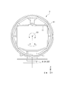
- FIG. 1 is a front view showing a radiation therapy system 1 according to the present embodiment.
- the radiation therapy system is a system including an apparatus that performs treatment by irradiating radiation toward a patient's body.
- the radiotherapy system 1 includes a couch 2, an O-ring unit 7 including an annular gantry 11, a PET detection device 12, an irradiation unit 15, and a rotation drive unit 20. Yes.
- the couch 2 is a device for placing a patient in the gantry 11.
- the couch 2 includes a base part 3, a bed 4 that moves relative to the base part 3, and a moving mechanism 6 that moves the bed 4 relative to the base part 3.
- the base unit 3 is mounted or fixed on the floor on which the radiation therapy system 1 is installed, and has a height corresponding to the height direction dimension of the gantry 11.
- the height of the base 3 is configured to be high enough to allow the bed 4 to be disposed at the approximate center of the annular gantry 11, and the exact position of the bed 4 is defined by the moving mechanism 6.
- the bed 4 has a substantially flat top surface portion 5.
- the top surface portion 5 is configured to be placed in a state in which the patient is sleeping or in a state where the patient is in a posture necessary for diagnosis or treatment.
- the moving mechanism 6 has a vertical axis Z1 and two horizontal axes X1, Y1 orthogonal to each other as degrees of freedom. That is, the moving mechanism 6 moves the bed 4 forward and backward in the direction of the vertical axis Z1, rotates the bed 4 around the vertical axis Z1, moves the bed 4 forward and backward in the directions of the horizontal axes X1 and Y1, and moves each of the horizontal axes X1. , Y1 can be rotated around the bed 4.
- the moving mechanism 6 is configured to move the bed 4 based on the result detected by the PET detection device 12 described later.
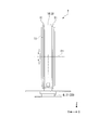
- FIG. 2 is a perspective view showing a part of the radiation therapy system 1 according to the present embodiment.
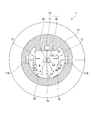
- FIG. 3 is a front view showing the internal structure of the radiation therapy system 1 according to the present embodiment.
- FIG. 4 is a perspective view showing the internal structure of the radiation therapy system 1 according to this embodiment.
- the O-ring portion 7 shown in FIG. 2 is a mechanism for placing a patient placed on the bed 4 of the couch 2 shown in FIG. 1 and receiving diagnosis and treatment.
- the O-ring portion 7 includes a base portion 8, an annular main body portion 9, and a gantry 11 connected to the main body portion 9.
- the base 8 is fixed to the floor on which the radiation therapy system 1 is installed, and supports the entire main body 9.
- a part of the base portion 8 is disposed on the floor surface, and the base portion 8 is provided with a horizontal swinging portion 21 that is a part of the rotation driving unit 20 in the present embodiment.
- the horizontal rocking portion 21 is a device that drives the O-ring portion 7 to rotate around a vertical axis passing through the rotation center O1 of the gantry 11 within a predetermined angle range.
- the main body 9 has an annular frame 10 whose lower end is connected to the base 8.
- the main body 9 swings around the vertical axis by a horizontal swinging portion 21 provided on the base 8.
- the center of the annular frame 10 in the main body portion 9 coincides with the rotation center O1 of the gantry 11, and becomes an isocenter in the radiation irradiated from the irradiation unit 15.
- the gantry 11 is an annular member that is arranged inside the frame 10 of the main body 9 and is rotated along the frame 10.
- the gantry 11 is provided with a PET detection device 12, an irradiation unit 15 that irradiates radiation, and a circumferential rotation unit 22 of the rotation drive unit 20.
- FIG. 5 is a partial cross-sectional view showing the PET detection apparatus 12 in the radiation therapy system 1 according to the present embodiment.
- the PET detection device 12 is provided to perform positron emission tomography (PET) on a patient, and includes a pair of photon detectors 13 and a photon detector moving device 14. Have.
- PET positron emission tomography
- the pair of photon detectors 13 are provided so as to face each other with the patient in between for the purpose of detecting photons emitted from the patient based on the decay of the tracer nuclide administered to the patient.
- the pair of photon detectors 13 are disposed to face each other with a predetermined rotation center O1 in the gantry 11 therebetween.
- radiation is irradiated from the irradiation unit 15 toward the rotation center O1 of the gantry 11, and the predetermined rotation center O1 becomes an isocenter in the radiation therapy system 1.
- each of the pair of photon detectors 13 has a flat plate shape.
- the photon detector 13 is connected to a PET diagnostic computer system (not shown).
- the photon detector moving device 14 is a device that connects the photon detector 13 to the gantry 11 and moves the photon detector 13 relative to the gantry 11.
- the photon detection unit moving device 14 is provided for the purpose of suppressing the adverse effect on the photon detection unit 13 due to the radiation irradiated from the irradiation unit 15 or the scattered radiation of the radiation hitting the photon detection unit 13. . That is, when detecting a photon in a PET examination, the photon detector moving device 14 arranges a pair of photon detectors 13 at a position (examination position A1) away from the patient by a predetermined distance.
- the photon detection unit moving device 14 is a position further away from the predetermined distance from the patient before radiation irradiation is started as necessary.
- the pair of photon detectors 13 are moved to the retreat position A2.
- the retreat position A2 is set based on the irradiation direction and irradiation range of the radiation irradiated from the irradiation unit 15.
- the retreat position A2 is located outside the radiation irradiation range and outside the range in which scattered radiation due to the radiation can reach the photon detection unit 13.
- the retreat position A ⁇ b> 2 is provided in the gantry 11.
- a pair of concave portions 11 ⁇ / b> A into which the pair of photon detectors 13 enter is opened on the inner peripheral surface of the gantry 11.
- the inside of the concave portion 11 ⁇ / b> A is set as the retracted position A ⁇ b> 2 of the photon detector 13.
- the photon detector moving device 14 is fixed to the inner surface of the concave portion 11A.
- a lid member that shields radiation or scattered rays can be disposed in the opening of the concave portion 11A as necessary.
- the photon detector moving device 14 can change the distance of the photon detector 13 with respect to the patient. For example, by changing the distance between the pair of photon detectors 13 by the photon detector moving device 14, the balance between sensitivity and resolution in the PET examination can be adjusted.
- the predetermined distance may be located within a radiation irradiation range or a range where scattered radiation due to radiation can reach the pair of photon detectors 13. This is because when the PET inspection is performed, no radiation is irradiated from the irradiation unit 15, so that no adverse effect on the photon detection unit 13 occurs.
- a known structure such as a linear motion mechanism using a ball screw or an expansion / contraction mechanism using a pantograph can be appropriately selected and employed.
- the irradiation part 15 shown in FIG. 5 irradiates a patient with the radiation emitted by the radiation generation source which is not illustrated.
- the irradiation unit 15 includes a kV-X-ray irradiation unit 16 and an MV beam irradiation unit 17.
- the kV-X-ray irradiation unit 16 emits kV-X-rays in order to obtain X-ray fluoroscopic imaging and X-ray CT images.
- the MV beam irradiation unit 17 irradiates the MV beam in order to treat the lesion T in the patient's body.
- the kV-X-ray irradiation unit 16 is provided at two locations with the MV beam irradiation unit 17 interposed therebetween. Further, a kV-X-ray detection unit 18 is provided on the opposite side of the rotation center O1 from the kV-X-ray irradiation unit 16. In addition, an MV beam detection unit 19 is provided on the opposite side of the rotation center O1 from the MV beam irradiation unit 17.
- the pair of photon detectors 13 is arranged on a line that intersects both the irradiation direction L1 of the kV-X ray and the irradiation direction L2 of the MV beam.
- the photon detection unit 13 is arranged on a line L3 orthogonal to the straight line connecting the MV beam irradiation unit 17 and the MV beam detection unit 19, and the pair of photon detection units 13 is moved back and forth along the line L3. It is comprised so that.
- a straight line connecting the MV beam irradiation unit 17 and the MV beam detection unit 19 coincides with the line indicating the irradiation direction L2.
- the rotation drive unit 20 rotates the gantry 11 around a predetermined rotation center O1.
- the “predetermined rotation center O1” is the center point of the gantry 11 formed in an annular shape.
- the rotation drive unit 20 includes a horizontal swing unit 21 and a circumferential direction rotation unit 22.
- the horizontal rocking portion 21 is provided for rotating the gantry 11 around a vertical axis passing through the center point.
- the circumferential rotation unit 22 is provided to rotate the gantry 11 in the circumferential direction with respect to the frame 10.
- the horizontal rocking part 21 and the circumferential rotation part 22 can be operated independently of each other.
- the rotation driving unit 20 rotates the gantry 11 around the predetermined rotation center O1, thereby rotating the irradiation unit 15 and the PET detection device 12 around the predetermined rotation center O1. As a result, the irradiation unit 15 and the PET detection device 12 are moved together while the relative positional relationship between the irradiation unit 15 and the PET detection device 12 is maintained.
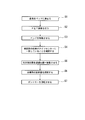
- FIG. 6 is a flowchart for explaining the operation at the time of use of the radiation therapy system 1 according to the present embodiment.
- a tracer nuclide specific to the lesion T is administered to the patient.
- the patient is placed on the bed 4 of the couch 2. Further, it is confirmed that the position of the lesioned part T grasped by a prior examination or the like is held in a body position capable of suitably irradiating radiation (step S1 shown in FIG. 6).
- the type of the tracer nuclide can be appropriately selected according to the inspection object.
- the X-ray imaging or the cone beam CT is used to collate with the image at the time of treatment planning of the patient, and the setup is performed with high accuracy.
- a PET inspection is performed using the PET detection apparatus 12 and the PET diagnostic computer system (step S2).
- the photon detection unit 13 is moved to a position where detection can be performed in the direction of irradiation of the treatment beam, and the lesioned part T is disposed between the pair of photon detection units 13. Then, at the timing when the tracer nuclide administered to the patient collapses, photons jump out of the patient's body.
- a detection signal is output from the photon detector 13 to the computer system for PET diagnosis.
- the position where the tracer nuclide is collapsed in the three-dimensional space is specified based on the incident state of the photon to the photon detector 13.
- the PET inspection a portion where the concentration of the tracer nuclide is high is detected based on the information on the position where the tracer nuclide is collapsed, and three-dimensional position information is obtained. Since the tracer nuclide accumulates specifically in the lesioned part T, three-dimensional position information of the lesioned part T can be obtained by the PET examination. In this embodiment, since the resolution in the photon detector plane direction is excellent, the three-dimensional position information of the lesion T can be acquired with high resolution by performing the PET examination from the two directions of the front and the side. .
- the moving mechanism 6 makes the position of the lesioned part T coincide with the isocenter (predetermined rotation center O1 in this embodiment).
- the bed 4 is moved (step S3). Thereafter, if necessary, it is confirmed by PET examination that the position of the lesion T matches the isocenter (step S4).
- FIG. 7 is an explanatory diagram showing a process during use of the radiotherapy system 1 according to the present embodiment, and shows a state in which the photon detection unit 13 is moved to the retracted position A2 after the PET examination is completed as necessary. Has been. After it is confirmed by PET examination that the position of the lesioned part T coincides with the isocenter, the photon detector moving device 14 moves the photon detector 13 into the concave part 11A (see step S5, FIG. 7). ). Thereby, the photon detection unit 13 is disposed at the retracted position A2 that is not affected by the radiation irradiated from the irradiation unit 15.
- the irradiation unit 15 is moved to the irradiation position by the rotation of the gantry, and then the MV beam is irradiated toward the isocenter (step S6). Since the couch 2 and the gantry 11 do not move from the end of the PET examination to the start of the MV beam irradiation, the patient on the bed 4 maintains the posture at the end of the PET examination. Thereby, at the time of irradiation with the MV beam, the position of the lesioned part T of the patient is located at the isocenter.
- step S7 After the necessary dose of MV beam is irradiated onto the lesioned part T, the irradiation of the MV beam from the irradiation unit 15 is stopped, and the gantry 11 is moved in the circumferential direction of the frame 10 by a predetermined angle (step S7).
- the gantry 11 is moved 45 ° in the circumferential direction of the frame 10 and stopped.
- the angle of the PET detection device 12 with respect to the lesioned part T and the angle of the irradiation unit 15 with respect to the lesioned part T are shifted from the predetermined angle.
- Step S2 to Step S6 are sequentially performed, and the lesioned part T is irradiated with the MV beam.
- step S7 is performed again to rotate the gantry 11 in the circumferential direction of the frame 10. Note that the step of confirming the position by PET inspection (step S4 above) can be omitted if unnecessary.
- the MV beam can be irradiated from different angles with respect to the isocenter. At this time, irradiation of radiation can be started without moving the bed 4 after performing the PET inspection. Thereby, it is possible to suppress the possibility that the patient's posture on the bed 4 is changed or the patient's position is shifted by moving the bed 4.
- the gantry 11 before irradiating the MV beam from the irradiation unit 15, the gantry 11 is rotated, and a plurality of PET inspection images are obtained from the angle at which the MV beam is irradiated. You may get it. Thereafter, the gantry 11 can be rotated to irradiate the MV beam irradiator at the above angle.
- the result of detecting the position of the lesioned part T by the PET examination is accurately reflected in the irradiation position of the radiation from the irradiation unit 15.
- a therapeutic beam for example, MV beam.
- BEV Beam's Eye View
- an image of the lesion T can be obtained from a plurality of directions using the PET detection device 12 provided in the rotating gantry 11.
- the three-dimensionally accurate position of the lesioned part T can be confirmed.
- one PET inspection image is acquired every 45 ° around the rotation center of the gantry 12, and an accurate position of the lesioned part T can be imaged by superimposing a plurality of PET inspection images. It is also possible to identify a three-dimensional tumor position from this result.
- the radiotherapy system 1 of the present embodiment when the photon detection unit moving device 14 retracts the pair of photon detection units 13 when irradiating the radiation from the irradiation unit 15, the radiation irradiated from the irradiation unit 15. The influence on the photon detection unit 13 due to can be suppressed low.
- the radiation treatment system 1 of the present embodiment since the gantry 11 is annular, it is possible to perform treatment with higher rigidity and higher positional accuracy than the case of having a conventional C-arm structure. Furthermore, since the pair of photon detectors 13 is arranged in the annular gantry 11 having high rigidity, the irradiation unit 15 and the photon detector 13 do not interfere with each other while maintaining high positional accuracy.
- the gantry 11 by placing the photon detection unit 13 in the concave shape portion 11A provided in the gantry 11, the gantry 11 allows the radiation and a part of its scattered radiation to be disposed. Can be shielded.
- the pair of photon detectors 13 are disposed to face each other with the isocenter interposed therebetween.
- the pair of photon detectors 13 are arranged at positions that do not interfere with the kV-X-ray irradiator 16, the MV beam irradiator 17, the kV-X-ray detector 18 and the MV beam detector 19 in the irradiator 15. PET inspection can be suitably performed in the state.
- the change in resolution due to the distance between the pair of photon detectors 13 is small. For this reason, at the time of PET examination, a pair of photon detection parts 13 can be brought close to a patient, and a highly sensitive PET examination can be performed.
- the radiation therapy system 1 of the present embodiment it is possible to perform X-ray fluoroscopic imaging and both CT examination and PET examination. For this reason, for example, when it is difficult to confirm the lesioned part T with an X-ray fluoroscopic image, the lesioned part T can be reliably identified by complementing each other's defects, such as confirming the lesioned part T by PET examination. .
- a detailed position of the lesioned part T by overlaying images obtained by the PET inspection Information and shape information can be obtained.
- the detailed position information and shape information obtained in this way may be used to perform irradiation from the steps S2 to S7.
- a treatment plan can be created using an image obtained by a PET examination, and radiation is irradiated along the treatment plan immediately after diagnosis by the PET examination. You can also. For example, in a case with bone metastasis, a rapid treatment can be performed by omitting a preliminary examination using another device for creating a treatment plan, so that a high therapeutic effect can be obtained.
- an example is shown in which a patient is treated by irradiating the patient with therapeutic X-rays.
- an apparatus for treating a patient by irradiating a patient with a radiation other than X-rays or a particle beam instead of the radiation and an irradiation field determining method can be similarly configured.
- Table 1 shows the configuration of an existing counter-type PET apparatus (comparative example) and the configuration of the PET detection apparatus (example) in this example.
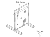
- FIG. 8A and 8B are schematic diagrams showing an experimental apparatus for examining the detection state of photons in the PET detection apparatus according to the present embodiment and the existing counter-type PET apparatus.
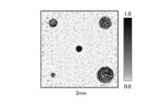
- FIG. 9 is a diagram illustrating detection results (examples) using the PET detection apparatus according to the present embodiment.
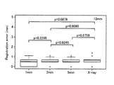
- FIG. 10 is a graph for explaining the accuracy of alignment when the PET detection apparatus according to the present embodiment is used.
- the three bars on the left are the position errors (Registration Error) when the exposure time to the radiation source imitating the 18F radioactive tracer nuclide (radiation source having a diameter of 12 mm shown in FIG. 8A) is 1 min, 3 min and 5 min, respectively. ),
- the rightmost bar indicates the position error in a control experiment using a fluoroscope.
- the PET detection apparatus according to the present embodiment can obtain an image of a radiation source in the same manner as the X-ray fluoroscopic apparatus.
- the alignment error is 1 mm or less, which suggests that the position of the lesioned part can be confirmed with an accuracy falling within the setup margin. It was.
- Table 1 above in this example, the number of detection elements is large and the detection area is wide as compared with the comparative example. Therefore, it is considered advantageous in terms of sensitivity and resolution.
- the radiotherapy system can be applied to an apparatus and a system for specifying a position where radiation irradiation is performed by a PET examination and irradiating the specified position with radiation.
Landscapes
- Health & Medical Sciences (AREA)
- Engineering & Computer Science (AREA)
- Life Sciences & Earth Sciences (AREA)
- Biomedical Technology (AREA)
- Medical Informatics (AREA)
- Pathology (AREA)
- Nuclear Medicine, Radiotherapy & Molecular Imaging (AREA)
- Radiology & Medical Imaging (AREA)
- Animal Behavior & Ethology (AREA)
- General Health & Medical Sciences (AREA)
- Public Health (AREA)
- Veterinary Medicine (AREA)
- Biophysics (AREA)
- High Energy & Nuclear Physics (AREA)
- Physics & Mathematics (AREA)
- Optics & Photonics (AREA)
- Heart & Thoracic Surgery (AREA)
- Molecular Biology (AREA)
- Surgery (AREA)
- Pulmonology (AREA)
- Theoretical Computer Science (AREA)
- Radiation-Therapy Devices (AREA)
- Nuclear Medicine (AREA)
- Apparatus For Radiation Diagnosis (AREA)
Abstract
Description
また、特許文献1に記載されたように患者を乗せたベッドを移動させる場合にも、ベッドを移動させることによってベッド上における患者の位置が変化する可能性があり、厳密な位置合わせが困難である。
なお、検出位置が前記X線の照射範囲外であれば一対の光子検出部の退避は不要である。
図1に示すように、放射線治療システム1は、カウチ2と、環状のガントリー11を備えたOリング部7と、PET用検出装置12と、照射部15と、回転駆動部20とを備えている。
図2に示すOリング部7は、図1に示すカウチ2のベッド4上に乗せられた患者が内部に配置され、診断および治療を受けるための機構である。図2ないし図4に示すように、Oリング部7は、基部8と、環状の本体部9と、本体部9に連結されたガントリー11とを備える。
図5に示すように、PET用検出装置12は、患者に対して陽電子放射断層撮影(PET)をするために設けられており、一対の光子検出部13と、光子検出部移動装置14とを有している。
本実施形態では、一対の光子検出部13の各々は平板形状を有する。また、光子検出部13は、図示しないPET診断用コンピュータシステムに接続されている。
光子検出部移動装置14の構造としては、ボールネジを用いた直動機構やパンタグラフを用いた伸縮機構等など、公知の構造を適宜選択して採用することができる。
本実施形態では、kV‐X線照射部16は、MVビーム照射部17を間に挟んで2箇所に設けられている。また、回転中心O1を挟んでkV‐X線照射部16と反対側には、kV‐X線検出部18が設けられている。また、回転中心O1を挟んでMVビーム照射部17と反対側には、MVビーム検出部19が設けられている。
図5に示すように、一対の光子検出部13は、kV‐X線の照射方向L1とMVビームの照射方向L2との両方に交差する線上に配置されている。具体的には、MVビーム照射部17とMVビーム検出部19とを結ぶ直線と直交する線L3上に光子検出部13が配置され、線L3に沿って一対の光子検出部13が進退動作されるように構成されている。本実施形態では、MVビーム照射部17とMVビーム検出部19とを結ぶ直線は、上記照射方向L2を示す線と一致している。
回転駆動部20は、ガントリー11を所定の回転中心O1回りに回転動作させることにより、照射部15およびPET用検出装置12を所定の回転中心O1回りに回転動作させる。これにより、照射部15とPET用検出装置12との相対位置関係が維持された状態で照射部15とPET用検出装置12とが一体として移動される。
放射線治療システム1の使用時には、まず、病変部Tに特異的なトレーサー核種を患者に投与する。その後、患者をカウチ2のベッド4に乗せる。さらに、事前の検査等によって把握した病変部Tの位置に好適に放射線を照射できる体位に保持されていることを確認する(図6に示すステップS1)。トレーサー核種の種類は、検査対象に対応して適宜選択することができる。
続いて、PET用検出装置12及びPET診断用コンピュータシステムを用いてPET検査を行なう(ステップS2)。
PET検査においては、まず、光子検出部13が治療ビームを照射する方向での検出ができる位置に移動され、病変部Tが一対の光子検出部13の間に配置される。すると、患者に投与されたトレーサー核種が崩壊したタイミングで、患者の体外に光子が飛び出す。患者を間に挟むように対向配置された一対の光子検出部13に光子が到達すると、光子検出部13からPET診断用コンピュータシステムへ検出信号が出力される。PET診断用コンピュータシステムでは、光子検出部13への光子の入射状態に基づいて、三次元空間内においてトレーサー核種が崩壊した位置が特定される。PET検査では、トレーサー核種が崩壊した位置の情報に基づいてトレーサー核種の濃度が高い部位を検出し、三次元の位置情報を得る。トレーサー核種は病変部Tへ特異的に集積するので、PET検査により病変部Tの三次元の位置情報が得られる。本実施形態では、光子検出器面方向の分解能が優れていることから、正面および側面の2方向からPET検査を行うことにより、病変部Tの三次元の位置情報を高分解能で取得可能である。
病変部Tの位置がアイソセンターに一致したことがPET検査により確認された後、光子検出部移動装置14によって、光子検出部13を凹形状部11A内へと移動させる(ステップS5、図7参照)。これにより、光子検出部13は、照射部15から照射される放射線の影響を受けない退避位置A2に配置される。
なお、位置確認をPET検査によって行なうステップ(上記ステップS4)は、不要な場合には省略することもできる。
また、光子検出面内の分解能に対して、面に垂直な方向の分解能を上げる手段として、回転するガントリー11に設けられたPET用検出装置12を用いて複数の方向から病変部Tの画像を取得し、病変部Tの三次元的に正確な位置を確認することができる。例えばガントリー12の回転中心回りに45°ごとに1枚のPET検査画像を取得し、複数のPET検査画像を重ね合わせることによって病変部Tの正確な位置を画像化することができる。また、この結果から3次元の腫瘍位置を同定することも可能である。
また、本実施形態の放射線治療システム1によれば、ガントリー11が環状であるので、従来のCアーム構造を有する場合と比較して剛性が高く、位置精度の高い治療をすることができる。さらに、剛性が高い環状のガントリー11に一対の光子検出部13が配置されているので、高い位置精度を保ちつつ、照射部15と光子検出部13とが干渉しない。
本実施例では、上記実施形態で説明した放射線治療システムと、既存の対向型PET装置とを比較して、病変部の位置を確認する際の感度及び精度に関する検討を行なった。
下記表1に、既存の対向型PET装置(比較例)の構成と、本実施例におけるPET用検出装置(実施例)の構成とを示す。

図9に示すように、本実施形態に係るPET用検出装置はX線透視装置と同様に放射線源の像を得ることができた。また、図10に示すように、本実施形態に係るPET用検出装置では、位置合わせの誤差は1mm以下であり、セットアップマージン内に収まる精度で病変部の位置を確認することができることが示唆された。
また、上記表1に示すように、本実施例では、比較例と比べて検出素子数が多く検出面積が広いので、感度及び分解能の面で有利であると考えられる。
2 カウチ
3 基台部
4 ベッド
5 天面部
6 移動機構
7 Oリング部
8 基部
9 本体部
10 フレーム
11 ガントリー
11A 凹形状部
12 PET用検出装置
13 光子検出部
14 光子検出部移動装置
15 照射部
16 kV‐X線照射部
17 MVビーム照射部
18 kV‐X線検出部
19 MVビーム検出部
20 回転駆動部
21 水平揺動部
22 周方向回転部
A1 検査位置
A2 退避位置
L1 kV‐X線の照射方向
L2 MVビームの照射方向
L3 光子検出部の配置及び移動方向を示す線
O1 回転中心
T 病変部
X1,Y1 水平軸
Z1 鉛直軸
Claims (11)
- 患者が内部に配置される環状のガントリーと、
前記ガントリーに設けられ前記患者に対して陽電子放射断層撮影(PET)をするためのPET用検出装置と、
前記ガントリーに設けられ前記患者に対してX線を照射する照射部と、
前記ガントリーを所定の回転中心回りに回転動作させる回転駆動部と、
を備え、
前記PET用検出装置は、
前記患者に投与されたトレーサー核種の核崩壊に基づいて患者から放出される光子を検出するために前記患者を間に挟んで対向配置された一対の光子検出部と、
前記一対の光子検出部と前記ガントリーとの各々に連結され前記ガントリーに対して前記一対の光子検出部を移動させる光子検出部移動装置と、
を有し、
前記回転駆動部は、
前記ガントリーを前記所定の回転中心回りに回転動作させることにより前記照射部および前記PET用検出装置を前記所定の回転中心回りに回転動作させ、
前記光子検出部移動装置は、
前記PETにおける光子の検出をする場合には前記患者から所定距離だけ離れた位置に前記一対の光子検出部を配置し、
前記照射部から前記患者へ前記X線を照射する場合には前記X線の照射が開始される前に前記一対の光子検出部を前記患者から前記所定距離よりもさらに離れた退避位置へ移動させるように構成された
X線治療システム。 - 請求項1に記載のX線治療システムであって、
前記退避位置は、前記X線の照射範囲外であって且つ前記X線による散乱線が前記一対の光子検出部に到達可能な範囲外に位置し、
前記所定距離は、前記X線の照射範囲内若しくは前記X線による散乱線が前記一対の光子検出部に到達可能な範囲内である
X線治療システム。 - 請求項1に記載のX線治療システムであって、
前記ガントリーの内周面には、前記一対の光子検出部が収納される一対の凹形状部が開口され、
前記凹形状部の内部が前記退避位置であるX線治療システム。 - 請求項1に記載のX線治療システムであって、
前記一対の光子検出部は前記所定の回転中心を間に挟んで対向配置されているX線治療システム。 - 請求項1に記載のX線治療システムであって、
前記一対の光子検出部はアイソセンターを間に挟んで対向配置されているX線治療システム。 - 請求項1に記載のX線治療システムであって、
前記照射部は、
X線透視画像とX線CT画像との少なくとも何れかを取得するためにkV‐X線を照射するkV‐X線照射部と、
前記患者の体内の病変部に対する治療をするためにMVビームを照射するMVビーム照射部と、
を有し、
前記一対の光子検出部は、前記kV‐X線の照射方向と前記MVビームの照射方向との両方に交差する線上に配置されているX線治療システム。 - 請求項1から請求項6のいずれか一項に記載のX線治療システムを用いた照射野決定方法であって、
前記X線を照射する所定の方向から前記一対の光子検出部を使用して患者の画像を取得し、前記画像に基づいて、MVビームの照射野内に病変部が含まれていることを確認し、
前記回転駆動部が前記ガントリーを回転させることによって前記ガントリーに設けられた前記照射部を回転させて前記照射部からの前記X線の照射方向を前記所定の方向とし、
前記照射部から前記X線を前記所定の方向へ照射する
照射野決定方法。 - 請求項7に記載の照射野決定方法であって、
前記画像の取得後前記X線の照射前に、前記回転駆動部が前記ガントリーを回転させることによって前記ガントリーに設けられた前記一対の光子検出部を回転させ、
前記一対の光子検出部を使用して前記所定の方向であって前記所定の方向とは異なる方向から前記画像とは異なる前記患者の第二の画像を取得し、
前記光子検出部を用いた画像の取得開始時から前記照射部を用いたX線の照射開始前までの間に前記X線の照射対象の位置を少なくとも前記画像と前記第二の画像とを用いて決定する照射野決定方法。 - 請求項7または請求項8に記載の照射野決定方法であって、
X線透視画像とPET画像とを重ねあわせることによって前記照射対象の位置を決定する照射野決定方法。 - 請求項7または請求項8に記載の照射野決定方法であって、
前記一対の光子検出部を使用して得られた画像に基づいて前記患者に対する治療計画を生成し、前記治療計画に沿って前記照射部から前記患者へ前記X線を照射する照射野決定方法。 - 請求項8に記載の照射野決定方法であって、
前記画像及び前記第二の画像に基づいて、前記MVビームの照射野内に病変部が含まれていることを確認する照射野決定方法。
Priority Applications (4)
| Application Number | Priority Date | Filing Date | Title |
|---|---|---|---|
| JP2014501977A JP5909275B2 (ja) | 2012-02-29 | 2012-12-25 | X線治療システム及び光子検出方法 |
| US14/380,968 US10124193B2 (en) | 2012-02-29 | 2012-12-25 | X-ray therapy system and irradiation field determining method |
| CN201280070714.9A CN104136078A (zh) | 2012-02-29 | 2012-12-25 | X射线治疗系统及照射场决定方法 |
| EP12869756.2A EP2821099B1 (en) | 2012-02-29 | 2012-12-25 | X-ray therapy system |
Applications Claiming Priority (2)
| Application Number | Priority Date | Filing Date | Title |
|---|---|---|---|
| JP2012-044535 | 2012-02-29 | ||
| JP2012044535 | 2012-02-29 |
Publications (1)
| Publication Number | Publication Date |
|---|---|
| WO2013128770A1 true WO2013128770A1 (ja) | 2013-09-06 |
Family
ID=49081989
Family Applications (1)
| Application Number | Title | Priority Date | Filing Date |
|---|---|---|---|
| PCT/JP2012/083484 Ceased WO2013128770A1 (ja) | 2012-02-29 | 2012-12-25 | X線治療システム及び照射野決定方法 |
Country Status (5)
| Country | Link |
|---|---|
| US (1) | US10124193B2 (ja) |
| EP (1) | EP2821099B1 (ja) |
| JP (1) | JP5909275B2 (ja) |
| CN (1) | CN104136078A (ja) |
| WO (1) | WO2013128770A1 (ja) |
Cited By (2)
| Publication number | Priority date | Publication date | Assignee | Title |
|---|---|---|---|---|
| CN104939847A (zh) * | 2014-03-25 | 2015-09-30 | 北京亿仁赛博医疗科技研发中心有限公司 | 一种直线加速器 |
| EP3097951A4 (en) * | 2014-01-21 | 2017-02-22 | Mitsubishi Heavy Industries, Ltd. | Radiation therapy apparatus |
Families Citing this family (10)
| Publication number | Priority date | Publication date | Assignee | Title |
|---|---|---|---|---|
| US9616251B2 (en) | 2014-07-25 | 2017-04-11 | Varian Medical Systems, Inc. | Imaging based calibration systems, devices, and methods |
| CN106215335A (zh) * | 2016-08-30 | 2016-12-14 | 北京大基康明医疗设备有限公司 | 一种具有pet显像功能的在束高能放疗装置 |
| EP3583981B1 (en) * | 2017-05-12 | 2020-12-23 | Neuboron Medtech Ltd. | Photon emission detection device and boron neutron capture therapy system having same |
| WO2020082206A1 (zh) * | 2018-10-22 | 2020-04-30 | 清华大学 | Ct成像和图像引导放射治疗装置 |
| CN111068186B (zh) * | 2018-10-22 | 2021-03-02 | 清华大学 | Ct成像和图像引导放射治疗装置 |
| TWI685710B (zh) * | 2018-12-03 | 2020-02-21 | 財團法人金屬工業研究發展中心 | X光裝置與其影像擷取方法 |
| US11179579B2 (en) | 2018-12-29 | 2021-11-23 | Tsinghua University | Tomographic imaging and image-guided radiation therapy apparatus |
| CN111375144B (zh) * | 2018-12-29 | 2021-03-05 | 清华大学 | 断层成像和图像引导放射治疗装置 |
| US20220219015A1 (en) * | 2021-01-11 | 2022-07-14 | James Chinan Chen | Method of treatment by radiotherapy |
| WO2022170602A1 (zh) * | 2021-02-10 | 2022-08-18 | 西安大医集团股份有限公司 | 机架、放射治疗设备及成像设备 |
Citations (3)
| Publication number | Priority date | Publication date | Assignee | Title |
|---|---|---|---|---|
| JP2005121530A (ja) | 2003-10-17 | 2005-05-12 | Shimadzu Corp | 医用画像診断装置 |
| JP2012005888A (ja) * | 2011-10-11 | 2012-01-12 | National Cancer Center | 荷電粒子線照射装置 |
| JP2012010759A (ja) * | 2010-06-29 | 2012-01-19 | Sumitomo Heavy Ind Ltd | 干渉判定装置 |
Family Cites Families (12)
| Publication number | Priority date | Publication date | Assignee | Title |
|---|---|---|---|---|
| JP2000105279A (ja) | 1998-09-30 | 2000-04-11 | Sumitomo Heavy Ind Ltd | 放射線治療領域設定方法、治療装置、治療計画作成装置、及び治療用データベースシステム |
| US7265356B2 (en) * | 2004-11-29 | 2007-09-04 | The University Of Chicago | Image-guided medical intervention apparatus and method |
| DE102006024244A1 (de) * | 2006-05-23 | 2007-11-29 | Siemens Ag | Positronen-Emissions-Tomograph und Verfahren zur Ermittlung einer bei einer Partikeltherapie applizierten Dosisverteilung |
| JP4228019B2 (ja) | 2007-02-16 | 2009-02-25 | 三菱重工業株式会社 | 医療装置 |
| WO2010013345A1 (ja) * | 2008-08-01 | 2010-02-04 | 独立行政法人放射線医学総合研究所 | 検出器シフト型放射線治療・pet複合装置 |
| US8461539B2 (en) | 2008-08-01 | 2013-06-11 | National Institute Of Radiological Sciences | Combined radiation therapy/pet apparatus |
| JP5120459B2 (ja) * | 2008-10-23 | 2013-01-16 | 株式会社島津製作所 | 粒子線治療装置 |
| JP5246895B2 (ja) * | 2009-03-23 | 2013-07-24 | 独立行政法人放射線医学総合研究所 | 検出器回動型放射線治療・画像化複合装置 |
| US8515011B2 (en) * | 2009-06-02 | 2013-08-20 | Mayo Foundation For Medical Education And Research | System and method for dose verification radiotherapy |
| CN101879071A (zh) | 2010-07-01 | 2010-11-10 | 上海世鹏实验室科技发展有限公司 | 一种放射治疗系统 |
| WO2012021459A1 (en) * | 2010-08-08 | 2012-02-16 | Accuray, Inc. | Radiation treatment delivery system with outwardly movable radiation treatment head extending from ring gantry |
| JP5504398B2 (ja) * | 2011-10-11 | 2014-05-28 | 住友重機械工業株式会社 | 荷電粒子線照射装置 |
-
2012
- 2012-12-25 EP EP12869756.2A patent/EP2821099B1/en not_active Not-in-force
- 2012-12-25 WO PCT/JP2012/083484 patent/WO2013128770A1/ja not_active Ceased
- 2012-12-25 US US14/380,968 patent/US10124193B2/en active Active
- 2012-12-25 CN CN201280070714.9A patent/CN104136078A/zh active Pending
- 2012-12-25 JP JP2014501977A patent/JP5909275B2/ja not_active Expired - Fee Related
Patent Citations (3)
| Publication number | Priority date | Publication date | Assignee | Title |
|---|---|---|---|---|
| JP2005121530A (ja) | 2003-10-17 | 2005-05-12 | Shimadzu Corp | 医用画像診断装置 |
| JP2012010759A (ja) * | 2010-06-29 | 2012-01-19 | Sumitomo Heavy Ind Ltd | 干渉判定装置 |
| JP2012005888A (ja) * | 2011-10-11 | 2012-01-12 | National Cancer Center | 荷電粒子線照射装置 |
Cited By (3)
| Publication number | Priority date | Publication date | Assignee | Title |
|---|---|---|---|---|
| EP3097951A4 (en) * | 2014-01-21 | 2017-02-22 | Mitsubishi Heavy Industries, Ltd. | Radiation therapy apparatus |
| US10143860B2 (en) | 2014-01-21 | 2018-12-04 | Hitachi, Ltd. | Radiation therapy apparatus |
| CN104939847A (zh) * | 2014-03-25 | 2015-09-30 | 北京亿仁赛博医疗科技研发中心有限公司 | 一种直线加速器 |
Also Published As
| Publication number | Publication date |
|---|---|
| EP2821099A4 (en) | 2015-10-07 |
| US20150065870A1 (en) | 2015-03-05 |
| JPWO2013128770A1 (ja) | 2015-07-30 |
| JP5909275B2 (ja) | 2016-04-26 |
| CN104136078A (zh) | 2014-11-05 |
| US10124193B2 (en) | 2018-11-13 |
| EP2821099B1 (en) | 2019-07-24 |
| EP2821099A1 (en) | 2015-01-07 |
Similar Documents
| Publication | Publication Date | Title |
|---|---|---|
| JP5909275B2 (ja) | X線治療システム及び光子検出方法 | |
| JP6853214B2 (ja) | 放射誘導の放射線治療の方法および装置 | |
| US9420975B2 (en) | Imaging facility and radiation therapy device | |
| JP4782680B2 (ja) | Pet−ctシステムにおける較正画像アライメント装置及び方法 | |
| US20160256713A1 (en) | Radiation Therapy Guided Using PET Imaging | |
| JP2007236729A (ja) | 放射線治療装置制御装置および放射線照射方法 | |
| CN101224324A (zh) | 带电粒子线照射装置 | |
| CN113874071B (zh) | 医用图像处理装置、存储介质、医用装置及治疗系统 | |
| CN106310528B (zh) | 一种治疗设备 | |
| JP5575557B2 (ja) | 干渉判定装置 | |
| US20120263272A1 (en) | X-ray imaging method and apparatus to reduce x-ray exposure of subject regions other than the diagnostically relevant subject region | |
| JP5078972B2 (ja) | 放射線治療装置制御方法および放射線治療装置制御装置 | |
| JP4898901B2 (ja) | 放射線治療装置制御装置および放射線照射方法 | |
| CN215691126U (zh) | 放疗系统 | |
| JP7140251B2 (ja) | 放射線撮影装置 | |
| CN206424436U (zh) | 一种治疗设备 | |
| WO2023176264A1 (ja) | 医用画像処理装置、治療システム、医用画像処理方法、およびプログラム | |
| JP2018099505A (ja) | X線診断装置、医用画像診断システム及び制御方法 | |
| CN108778137B (zh) | 混合x射线和伽马成像系统 | |
| CN105919557B (zh) | 多模态成像系统及应用其的多模态成像方法 | |
| JP4763361B2 (ja) | X線ct装置 | |
| JP2011050416A (ja) | 放射線断層撮影方法 | |
| JP2012120742A (ja) | 放射線断層撮影装置 |
Legal Events
| Date | Code | Title | Description |
|---|---|---|---|
| 121 | Ep: the epo has been informed by wipo that ep was designated in this application |
Ref document number: 12869756 Country of ref document: EP Kind code of ref document: A1 |
|
| ENP | Entry into the national phase |
Ref document number: 2014501977 Country of ref document: JP Kind code of ref document: A |
|
| WWE | Wipo information: entry into national phase |
Ref document number: 14380968 Country of ref document: US |
|
| WWE | Wipo information: entry into national phase |
Ref document number: 2012869756 Country of ref document: EP |
|
| NENP | Non-entry into the national phase |
Ref country code: DE |