WO2013129349A1 - 熱源システム及びその熱媒流量制御方法 - Google Patents
熱源システム及びその熱媒流量制御方法 Download PDFInfo
- Publication number
- WO2013129349A1 WO2013129349A1 PCT/JP2013/054845 JP2013054845W WO2013129349A1 WO 2013129349 A1 WO2013129349 A1 WO 2013129349A1 JP 2013054845 W JP2013054845 W JP 2013054845W WO 2013129349 A1 WO2013129349 A1 WO 2013129349A1
- Authority
- WO
- WIPO (PCT)
- Prior art keywords
- opening
- differential pressure
- target value
- flow rate
- value
- Prior art date
- Legal status (The legal status is an assumption and is not a legal conclusion. Google has not performed a legal analysis and makes no representation as to the accuracy of the status listed.)
- Ceased
Links
Images






Classifications
-
- F—MECHANICAL ENGINEERING; LIGHTING; HEATING; WEAPONS; BLASTING
- F24—HEATING; RANGES; VENTILATING
- F24D—DOMESTIC- OR SPACE-HEATING SYSTEMS, e.g. CENTRAL HEATING SYSTEMS; DOMESTIC HOT-WATER SUPPLY SYSTEMS; ELEMENTS OR COMPONENTS THEREFOR
- F24D19/00—Details
- F24D19/10—Arrangement or mounting of control or safety devices
- F24D19/1006—Arrangement or mounting of control or safety devices for water heating systems
- F24D19/1009—Arrangement or mounting of control or safety devices for water heating systems for central heating
- F24D19/1012—Arrangement or mounting of control or safety devices for water heating systems for central heating by regulating the speed of a pump
-
- H—ELECTRICITY
- H05—ELECTRIC TECHNIQUES NOT OTHERWISE PROVIDED FOR
- H05K—PRINTED CIRCUITS; CASINGS OR CONSTRUCTIONAL DETAILS OF ELECTRIC APPARATUS; MANUFACTURE OF ASSEMBLAGES OF ELECTRICAL COMPONENTS
- H05K7/00—Constructional details common to different types of electric apparatus
- H05K7/20—Modifications to facilitate cooling, ventilating, or heating
- H05K7/20218—Modifications to facilitate cooling, ventilating, or heating using a liquid coolant without phase change in electronic enclosures
- H05K7/20272—Accessories for moving fluid, for expanding fluid, for connecting fluid conduits, for distributing fluid, for removing gas or for preventing leakage, e.g. pumps, tanks or manifolds
-
- F—MECHANICAL ENGINEERING; LIGHTING; HEATING; WEAPONS; BLASTING
- F24—HEATING; RANGES; VENTILATING
- F24F—AIR-CONDITIONING; AIR-HUMIDIFICATION; VENTILATION; USE OF AIR CURRENTS FOR SCREENING
- F24F11/00—Control or safety arrangements
- F24F11/70—Control systems characterised by their outputs; Constructional details thereof
- F24F11/80—Control systems characterised by their outputs; Constructional details thereof for controlling the temperature of the supplied air
- F24F11/81—Control systems characterised by their outputs; Constructional details thereof for controlling the temperature of the supplied air by controlling the air supply to heat-exchangers or bypass channels
-
- F—MECHANICAL ENGINEERING; LIGHTING; HEATING; WEAPONS; BLASTING
- F24—HEATING; RANGES; VENTILATING
- F24D—DOMESTIC- OR SPACE-HEATING SYSTEMS, e.g. CENTRAL HEATING SYSTEMS; DOMESTIC HOT-WATER SUPPLY SYSTEMS; ELEMENTS OR COMPONENTS THEREFOR
- F24D19/00—Details
- F24D19/10—Arrangement or mounting of control or safety devices
- F24D19/1006—Arrangement or mounting of control or safety devices for water heating systems
- F24D19/1009—Arrangement or mounting of control or safety devices for water heating systems for central heating
- F24D19/1015—Arrangement or mounting of control or safety devices for water heating systems for central heating using a valve or valves
- F24D19/1021—Arrangement or mounting of control or safety devices for water heating systems for central heating using a valve or valves a by pass valve
-
- F—MECHANICAL ENGINEERING; LIGHTING; HEATING; WEAPONS; BLASTING
- F24—HEATING; RANGES; VENTILATING
- F24D—DOMESTIC- OR SPACE-HEATING SYSTEMS, e.g. CENTRAL HEATING SYSTEMS; DOMESTIC HOT-WATER SUPPLY SYSTEMS; ELEMENTS OR COMPONENTS THEREFOR
- F24D19/00—Details
- F24D19/10—Arrangement or mounting of control or safety devices
- F24D19/1006—Arrangement or mounting of control or safety devices for water heating systems
- F24D19/1009—Arrangement or mounting of control or safety devices for water heating systems for central heating
- F24D19/1015—Arrangement or mounting of control or safety devices for water heating systems for central heating using a valve or valves
- F24D19/1036—Having differential pressure measurement facilities
-
- F—MECHANICAL ENGINEERING; LIGHTING; HEATING; WEAPONS; BLASTING
- F24—HEATING; RANGES; VENTILATING
- F24F—AIR-CONDITIONING; AIR-HUMIDIFICATION; VENTILATION; USE OF AIR CURRENTS FOR SCREENING
- F24F11/00—Control or safety arrangements
- F24F11/70—Control systems characterised by their outputs; Constructional details thereof
- F24F11/80—Control systems characterised by their outputs; Constructional details thereof for controlling the temperature of the supplied air
- F24F11/83—Control systems characterised by their outputs; Constructional details thereof for controlling the temperature of the supplied air by controlling the supply of heat-exchange fluids to heat-exchangers
-
- F—MECHANICAL ENGINEERING; LIGHTING; HEATING; WEAPONS; BLASTING
- F24—HEATING; RANGES; VENTILATING
- F24F—AIR-CONDITIONING; AIR-HUMIDIFICATION; VENTILATION; USE OF AIR CURRENTS FOR SCREENING
- F24F11/00—Control or safety arrangements
- F24F11/70—Control systems characterised by their outputs; Constructional details thereof
- F24F11/80—Control systems characterised by their outputs; Constructional details thereof for controlling the temperature of the supplied air
- F24F11/83—Control systems characterised by their outputs; Constructional details thereof for controlling the temperature of the supplied air by controlling the supply of heat-exchange fluids to heat-exchangers
- F24F11/84—Control systems characterised by their outputs; Constructional details thereof for controlling the temperature of the supplied air by controlling the supply of heat-exchange fluids to heat-exchangers using valves
-
- F—MECHANICAL ENGINEERING; LIGHTING; HEATING; WEAPONS; BLASTING
- F24—HEATING; RANGES; VENTILATING
- F24F—AIR-CONDITIONING; AIR-HUMIDIFICATION; VENTILATION; USE OF AIR CURRENTS FOR SCREENING
- F24F11/00—Control or safety arrangements
- F24F11/70—Control systems characterised by their outputs; Constructional details thereof
- F24F11/80—Control systems characterised by their outputs; Constructional details thereof for controlling the temperature of the supplied air
- F24F11/83—Control systems characterised by their outputs; Constructional details thereof for controlling the temperature of the supplied air by controlling the supply of heat-exchange fluids to heat-exchangers
- F24F11/85—Control systems characterised by their outputs; Constructional details thereof for controlling the temperature of the supplied air by controlling the supply of heat-exchange fluids to heat-exchangers using variable-flow pumps
-
- H—ELECTRICITY
- H05—ELECTRIC TECHNIQUES NOT OTHERWISE PROVIDED FOR
- H05K—PRINTED CIRCUITS; CASINGS OR CONSTRUCTIONAL DETAILS OF ELECTRIC APPARATUS; MANUFACTURE OF ASSEMBLAGES OF ELECTRICAL COMPONENTS
- H05K7/00—Constructional details common to different types of electric apparatus
- H05K7/20—Modifications to facilitate cooling, ventilating, or heating
- H05K7/20218—Modifications to facilitate cooling, ventilating, or heating using a liquid coolant without phase change in electronic enclosures
- H05K7/20281—Thermal management, e.g. liquid flow control
-
- Y—GENERAL TAGGING OF NEW TECHNOLOGICAL DEVELOPMENTS; GENERAL TAGGING OF CROSS-SECTIONAL TECHNOLOGIES SPANNING OVER SEVERAL SECTIONS OF THE IPC; TECHNICAL SUBJECTS COVERED BY FORMER USPC CROSS-REFERENCE ART COLLECTIONS [XRACs] AND DIGESTS
- Y02—TECHNOLOGIES OR APPLICATIONS FOR MITIGATION OR ADAPTATION AGAINST CLIMATE CHANGE
- Y02B—CLIMATE CHANGE MITIGATION TECHNOLOGIES RELATED TO BUILDINGS, e.g. HOUSING, HOUSE APPLIANCES OR RELATED END-USER APPLICATIONS
- Y02B30/00—Energy efficient heating, ventilation or air conditioning [HVAC]
- Y02B30/70—Efficient control or regulation technologies, e.g. for control of refrigerant flow, motor or heating
Definitions
- the present invention relates to a heat source system and a heat medium flow rate control method thereof.
- Patent Document 1 discloses a heat source system including a pump operation state control device that controls the rotation speed of an inverter-driven liquid feed pump and a flow rate control device that controls the flow rate of a heat medium in each load piping system.
- the operating state control device of the liquid feed pump outputs a valve fully open command to the flow control valve of the load piping system having the maximum heat medium flow rate, and sends it so as to obtain a desired flow rate.
- the number of rotations of the liquid pump is controlled, and the flow rate of other piping systems with a small required flow rate is controlled by the opening degree of each flow control valve.
- An object of the present invention is to provide a heat source flow rate control method and a heat medium flow rate control method capable of realizing heat saving flow control without depending on the scale and piping system on the load side, and further energy saving. To do.
- a heat source means for producing a heat medium having a desired temperature and supplying the heat medium to a load, a first pipe for supplying the heat medium from the heat source means to the load, and the first pipe.
- a supply header provided in the load, a second pipe for supplying the heat medium used in the load to the heat source means, a return header provided in the second pipe, and a heat medium from the supply header to the return header.
- a pump provided downstream from the return header in the flow of the heat medium and having a variable rotation speed
- a control means for adjusting the valve opening of the bypass valve;
- An opening command value determining means for determining a bypass valve opening command value so that a header differential pressure between the ply header and the return header matches a differential pressure target value; and a header differential pressure or bypass valve opening Opening target value setting means for setting the target opening value according to the behavior of the degree of opening, and the relationship between the bypass valve opening instruction value and the heat medium flow rate setting value is defined in association with the opening target value.
- a heat source system including a heat medium flow rate setting means for acquiring a heat medium flow rate setting value to perform frequency control of the pump according to the heat medium flow rate setting value.
- the bypass valve opening command value such that the header differential pressure matches the differential pressure target value is determined by the opening command value determination means, and the header differential pressure or bypass valve is determined by the opening target value setting means.
- An opening target value corresponding to the behavior of the opening is set.
- the heating medium flow rate setting means determines the heating medium flow rate setting value using the opening degree target value set by the opening degree target value setting unit and the opening degree command value determined by the opening degree command value determination means. .
- the flow control of the heat medium can be completed on the heat source system side.
- the opening target value setting means is within a predetermined range in which a deviation between the bypass valve opening and the opening target value is set in advance, and the header differential pressure is equal to or less than the differential pressure target value.
- the currently set opening target value is decreased, and the opening flow rate characteristic has the same bypass valve opening command value as the opening target value decreases. It may be set so that the heat medium flow rate setting value with respect to is small.
- the target opening value is reduced. That is, in a state where the header differential pressure is equal to or lower than the differential pressure target value, this indicates that the bypass flow rate is excessive, in other words, the bypass valve may be slightly throttled. Therefore, in such a state, the heating medium flow rate setting value obtained from the opening flow rate characteristic is lowered by lowering the opening target value. Thereby, the frequency of a pump can be lowered
- the header differential pressure corresponding to the heat medium flow rate corresponding to the deviation between the bypass valve opening and the target opening is calculated.
- the bypass valve opening corresponding to the changed differential pressure target value is calculated from the differential pressure opening characteristic.
- the acquired bypass valve opening degree is set as an opening target value, and the differential pressure opening characteristic may be set so that the opening target value decreases as the differential pressure target value decreases.
- the bypass valve opening when the bypass valve opening is larger than the opening target value, the bypass valve opening is used as a correction value, the differential pressure target value is decreased, and further, the differential pressure target value is changed. As a result, the opening target value decreases.
- the heat medium flow rate set value obtained from the opening degree flow rate characteristic can be reduced. Thereby, the frequency of a pump can be lowered
- a heat source means for producing a heat medium having a desired temperature and supplying the load to the load, a first pipe for supplying the heat medium from the heat source means to the load, and the first pipe.
- a supply header provided in the load, a second pipe for supplying the heat medium used in the load to the heat source means, a return header provided in the second pipe, and a heat medium from the supply header to the return header.
- a bypass pipe to be bypassed a bypass valve that is provided in the bypass pipe and adjusts a bypass flow rate of the heat medium, and an upstream side of the heat medium flow from the supply header in the first pipe, or the second pipe
- Opening command value for determining a bypass valve opening command value such that a header differential pressure, which is a differential pressure between the supply header and the return header, matches a differential pressure target value.
- the relationship between the determination process, the opening target value setting process that sets the opening target value according to the header differential pressure or the behavior of the bypass valve opening, and the relationship between the bypass valve opening instruction value and the heat medium flow rate setting value The opening command value is determined by using the opening flow characteristic corresponding to the opening target value set in the opening target value setting process.
- a heat medium flow rate setting process for obtaining a heat medium flow rate setting value corresponding to the opening command value determined in the process, and the heat of the heat source system in which frequency control of the pump is performed according to the heat medium flow rate setting value This is a medium flow rate control method.
- flow rate control can be realized regardless of the load-side scale and the piping system, and further, energy saving can be achieved.
- FIG. 1 is a diagram schematically showing a configuration of a heat source system according to the first embodiment of the present invention.
- the heat source system 1 includes, for example, a plurality of heat source units 11a, 11b, and 11c that cool or heat a heat medium (cold water) supplied to an external load such as an air conditioner, a water heater, or a factory facility. It has.
- FIG. 1 illustrates the case where three heat source units 11a, 11b, and 11c are installed, the number of installed heat source units can be arbitrarily determined.
- Pumps 12a, 12b, and 12c for pumping the heat medium are installed on the upstream side of the heat source devices 11a, 11b, and 11c as viewed from the heat medium flow.
- the heat medium from the return header 14 is sent to the heat source units 11a, 11b, and 11c by the pumps 12a, 12b, and 12c.
- Each pump 12a, 12b, 12c is driven by an inverter motor (not shown), whereby variable flow rate control is performed by making the rotation speed variable.
- the heat medium cooled or heated by the heat source devices 11a, 11b, and 11c is collected.
- the heat medium collected in the supply header 13 is supplied to an external load.
- the heat medium that has been subjected to air conditioning or the like by an external load and heated or cooled is sent to the return header 14.
- the heat medium is branched at the return header 14 and sent again to the heat source units 11a, 11b, and 11c.
- bypass pipe 18 is provided between the supply header 13 and the return header 14.
- the bypass pipe 18 is provided with a bypass valve 19 for adjusting the bypass flow rate.
- valve opening control of the bypass valve 19 and the inverter control of the pumps 12a, 12b, and 12c are performed by a host control device (control means) 20.
- FIG. 2 is a diagram schematically showing the configuration of the control system of the heat source system 1 shown in FIG.
- the heat source device control devices 10a, 10b, and 10c which are control devices for the heat source devices 11a, 11b, and 11c, are connected to the host control device 20 via a communication medium 21, and are bidirectional. Communication is possible.
- the host controller 20 is, for example, a controller that controls the heat source system 1 as a whole, and is based on the pressure difference between the supply header 13 and the return header 14 (hereinafter referred to as “header differential pressure”).
- the heat source apparatus 11a, 11b, 11c is a heat medium flow rate setting value that is a command for causing the heat source apparatus control devices 10a, 10b, 10c to control the rotational speed of the pumps 12a, 12b, 12c.
- the host control device 20 may also perform heat source unit number control for controlling the number of heat source units 11a, 11b, and 11c to be activated with respect to a required load of an external load, for example.
- the host control device 20 and the heat source device control devices 10a, 10b, and 10c are, for example, computers, a main storage device such as a CPU (Central Processing Unit), a RAM (Random Access Memory), an auxiliary storage device, and an external device.
- a communication device that exchanges information by performing communication is provided.
- the auxiliary storage device is a computer-readable recording medium, such as a magnetic disk, a magneto-optical disk, a CD-ROM, a DVD-ROM, or a semiconductor memory.
- Various programs are stored in the auxiliary storage device, and various processes are realized by the CPU reading and executing the program from the auxiliary storage device to the main storage device.
- FIG. 3 is a functional block diagram mainly showing functions related to valve opening control of the bypass valve 19 among various control functions provided in the host controller 20.
- the host controller 20 includes an opening command value determination unit 22, a heat medium flow rate setting unit 23, and an opening target value setting unit 24.
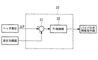
- the opening command value determining unit 22 determines a bypass valve opening command value that makes the header differential pressure ⁇ P coincide with a preset differential pressure target value. Specifically, as shown in FIG. 4, the opening command value determination unit 22 calculates a deviation (difference) between the differential pressure target value and the header differential pressure ⁇ P, and with respect to the differential pressure, And a PI control unit 32 for performing PI control. The output of the PI control unit 32 is given to the bypass valve 19 as a bypass valve opening command value, and is also output to the heat medium flow rate setting unit 23 for use.
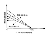
- the heat medium flow rate setting unit 23 has an opening flow rate characteristic in which the relationship between the bypass valve opening instruction value and the heat medium flow rate set value is defined in association with the target opening value.
- FIG. 5 shows an example of the opening flow rate characteristic.
- the horizontal axis represents the bypass valve opening command value
- the vertical axis represents the heat medium flow rate setting value.
- the opening flow rate characteristic is characterized in that the heat medium flow rate setting value decreases as the bypass valve opening command value increases, and the heat medium flow rate with respect to the same bypass valve opening command value as the opening target value decreases.
- the setting value is set to be small. In other words, the inclination is set to increase as the opening target value increases.
- the opening flow rate characteristic may be held as a table as shown in FIG. 5 or as an arithmetic expression of a heat medium flow rate setting value including the opening target value and the bypass valve opening command value as parameters. It may be.
- the heat medium flow rate setting unit 23 uses the opening flow rate characteristic corresponding to the target opening value set by the target opening value setting unit 24 described later, and opens the bypass valve determined by the opening command value determination unit 22.
- the heat medium flow rate setting value corresponding to the degree command value is acquired.
- the acquired heat medium flow rate setting value is transmitted from, for example, the host controller 20 to the heat source device control devices 10a, 10b, and 10c, and the frequency control of the pumps 12a, 12b, and 12c is performed based on the heat medium flow rate setting value. Is called.
- the rotation speeds of the pumps 12a, 12b, and 12c are controlled so that the sum of the flow rates sent from the pumps becomes the heat medium flow rate set value.
- the opening target value setting unit 24 sets the opening target value according to the header differential pressure ⁇ P or the behavior of the bypass valve opening.
- the opening target value setting unit 24 holds, for example, an initial value (for example, 10 [%]) of the opening target value, and sets the opening target value to the initial value when the heat source system 1 is started. To do. Thereafter, when the header differential pressure ⁇ P or the bypass valve opening changes in accordance with the required load or the like, the opening target value is changed in accordance with these states.
- the change of the target opening value by the target opening value setting unit 24 is performed, for example, according to the processing procedure shown in FIG. First, it is determined whether or not the absolute value of the deviation between the bypass valve opening and the target opening is equal to or less than a first threshold value set in advance (step SA1 in FIG. 6), and the bypass valve opening and opening are determined. If the absolute value of the deviation from the target value is less than or equal to the first threshold value (for example, within ⁇ 0.5 [%] with respect to the opening target value), the header differential pressure target value ⁇ P is set in advance. It is determined whether or not (for example, 200 [kPa]) or less (step SA2).
- step SA3 if the header differential pressure ⁇ P is equal to or lower than the differential pressure target value, it is determined whether or not the state is maintained for a preset first period (for example, 60 [sec]) (step SA3).
- the target opening value is set to a predetermined amount at a predetermined rate (for example, 0.1 [% min]). (Step SA4), and the process returns to step SA1.
- Step SA5 when the header differential pressure ⁇ P is larger than the differential pressure target value in step SA2, it is determined whether or not the state is maintained for a preset second period (for example, 60 [sec]) ( Step SA5).
- the target opening value is set to a predetermined amount at a predetermined rate (for example, 0.1 [% min]). (Step SA6), and the process returns to step SA1.
- step SA1 if the absolute value of the deviation between the bypass valve opening and the target opening value is larger than the first threshold, if the state is not maintained for the first period in step SA3, then in step SA5. When the said state is not maintained for the 2nd period, it returns to step SA1, without changing an opening target value.
- the first period and the second period may be set to the same value or may be set to different values.
- the heat medium flow control executed by the host controller 20 having the above-described functions will be described.
- an initial value preset by the opening target value setting unit 24 is set as the opening target value.
- the opening command value determining unit 22 determines a bypass valve opening command value based on the differential pressure target value and the header differential pressure ⁇ P, and the heat medium flow rate setting value corresponding to the bypass valve opening command value is the heat medium flow rate.
- the setting unit 23 sets by the setting unit 23.
- the header differential pressure ⁇ P is controlled to coincide with the differential pressure target value, and the heat medium flow rate setting according to the bypass valve opening command value is set.
- the flow rate of the heat medium is adjusted by adjusting the frequency of each pump 12a, 12b, 12c based on the value.
- the target opening value setting unit 24 decreases the target opening value by a predetermined amount. Thereafter, as long as the conditions from step SA1 to step SA3 are satisfied, the target opening value continuously decreases by a predetermined amount.
- the opening flow rate characteristic referred to by the heat medium flow setting unit 23 is changed, and the heat medium flow set value for the same bypass valve opening command value is reduced.
- the flow rate set value set by the heat medium flow rate setting unit 23 is decreased, and accordingly, the rotational speed of the pumps 12a, 12b, 12c is controlled to decrease, and the overall flow rate of the heat medium is decreased.
- the header differential pressure ⁇ P decreases.
- the bypass valve opening command value is adjusted in a decreasing direction (closing direction) in order to make the header differential pressure ⁇ P coincide with the differential pressure target value. Thereby, the bypass valve flow rate decreases.
- the header differential pressure ⁇ P tends to increase.
- the absolute value of the deviation between the bypass valve opening and the opening target value is equal to or less than the first threshold (“YES” in step SA1 in FIG. 6), and the header differential pressure ⁇ P is equal to the differential pressure target value.
- the opening target value setting unit 24 increases the opening target value by a predetermined amount (step SA6). Thereafter, as long as the conditions of Step SA1 and Step SA5 are satisfied, the target opening value is continuously increased by a predetermined amount.
- the opening flow characteristic referred to by the heat medium flow setting unit 23 is changed, and the flow set value for the same bypass valve opening command value increases. Thereby, the flow rate set value set by the heat medium flow rate setting unit 23 increases, and the rotational speed of the pump also increases.
- the bypass valve opening command value is controlled to increase (opening direction) in order to make the header differential pressure ⁇ P coincide with the differential pressure target value.
- the flow rate of the bypass valve increases.
- the header differential pressure ⁇ P tends to decrease.
- the state in which the deviation between the bypass valve opening and the opening target value is equal to or smaller than the first threshold and the header differential pressure ⁇ P is equal to or smaller than the differential pressure target value is maintained for the first period. If it is, control is performed to reduce the target opening value. That is, when the header differential pressure ⁇ P is equal to or lower than the differential pressure target value, the bypass flow rate is excessive, in other words, the bypass valve 19 may be slightly throttled. Therefore, in such a state, the bypass valve opening degree is decreased to reduce the bypass flow rate, and the excess heat medium flow rate absorbed as the bypass flow rate is reduced by reducing the rotational speed of the pumps 12a to 12c. Absorb.
- the opening degree of the bypass valve is controlled as close as possible, and the heat medium flow rate increased by closing the opening degree of the bypass valve is absorbed by reducing the frequency of the pumps 12a to 12c.
- the power consumption of ⁇ 12c can be reduced, and energy saving can be achieved.
- the opening target value is 10 [%]
- the bypass amount corresponds to 5 [%] of the water supply flow rate (flow rate supplied to the external load + bypass amount)
- the opening target If the value is reduced to 5 [%] the bypass amount can be reduced to 2.5 [%] of the water supply flow rate.
- the pump can be operated with the heat medium flow rate reduced by 2.5 [%] while maintaining the same head.
- the inverter frequency of the pump can be reduced by 1 [%].
- the power consumption is proportional to the cube of the frequency command, the power consumption can be reduced by 2 [%].
- FIG. 8 is a functional block diagram mainly showing functions related to heat medium flow rate control in the host controller 20 according to the present embodiment.
- the host controller 20 ′ according to the present embodiment has a point that a differential pressure target value setting unit 25 is added to the configuration shown in FIG.
- the part 24 ′ is different in that it further has a function of changing the target opening value with the change of the differential pressure target value.
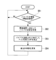
- the change of the differential pressure target value by the differential pressure target value setting unit 25 is performed, for example, according to the processing procedure shown in FIG. First, it is determined whether or not the bypass valve opening is larger than the target opening (step SB1 in FIG. 9), and when the bypass valve opening is larger than the target opening, the heat medium flow rate setting unit 23 By referring to the opening flow rate characteristics possessed (see FIG. 5), a bypass flow rate corresponding to the deviation between the bypass valve opening and the opening target value is acquired (step SB2 in FIG. 9). At this time, the opening flow rate characteristic refers to the one corresponding to the current opening degree target value set by the opening degree target value setting unit 24.
- the differential pressure target value setting unit 25 calculates a header differential pressure ⁇ BP corresponding to the bypass flow rate ⁇ BT (step SB3 in FIG. 9).
- the differential pressure target value setting unit 25 has an arithmetic expression of the header differential pressure ⁇ BP including the bypass flow rate ⁇ BT as a parameter, and calculates the header differential pressure ⁇ BP corresponding to the bypass flow rate ⁇ BT using this arithmetic expression.
- the differential pressure target value setting unit 25 uses the header differential pressure ⁇ BP as a correction value, decreases the current differential pressure target value (step SB4 in FIG. 9), and returns to step SB1.
- the target opening value setting unit 24 ' changes the target opening value based on the changed differential pressure target value.
- the opening target value setting unit 24 ′ has a differential pressure opening characteristic in which the relationship between the header differential pressure and the bypass valve opening is defined.
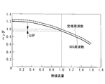
- FIG. 11 shows an example of the differential pressure opening characteristic.
- the horizontal axis indicates the header differential pressure (differential pressure target value), and the vertical axis indicates the bypass valve opening.
- the differential pressure opening characteristic is set so that the bypass valve opening also decreases as the header differential pressure decreases.
- the differential pressure opening characteristic may be held as a table as shown in FIG. 11, or may be held as an arithmetic expression for the bypass valve opening including the header differential pressure as a parameter.
- the opening target value setting unit 24 ′ acquires the bypass valve opening corresponding to the changed differential pressure target value from the differential pressure opening characteristic. Then, the current opening target value is changed to the acquired bypass valve opening.
- the rotational speed of the pump can be reduced as described in the first embodiment. Thereby, energy saving can be achieved.
- the heat source system and the heating medium flow rate control method when the bypass valve opening is larger than the opening target value, the heating medium corresponding to the deviation of the opening.
- the flow rate is calculated, and further, the header differential pressure ⁇ BP corresponding to the heat medium flow rate is calculated, and the differential pressure target value is updated in a direction of decreasing according to the header differential pressure ⁇ BP. Further, as the differential pressure target value is decreased, the opening target value is also decreased.
- the flow rate setting value for the same bypass valve opening command value can be reduced (see FIG. 5), and the rotation speed of the pumps 12a to 12c is reduced. It becomes possible.
- the differential pressure target value is set to 200 [kPa]
- the same heat medium flow rate is supplied by reducing the differential pressure target value by 10 [kPa]
- the inverter frequency of the pump can be reduced by 2 [%] compared to the case where the rated flow rate is maintained.
- the power consumption is proportional to the cube of the frequency command, the power consumption can be reduced by 6 [%].
Landscapes
- Engineering & Computer Science (AREA)
- Chemical & Material Sciences (AREA)
- Combustion & Propulsion (AREA)
- Mechanical Engineering (AREA)
- General Engineering & Computer Science (AREA)
- Physics & Mathematics (AREA)
- Thermal Sciences (AREA)
- Microelectronics & Electronic Packaging (AREA)
- Air Conditioning Control Device (AREA)
Description
以下に、本発明の第1実施形態に係る熱源システム及びその熱媒流量制御方法について、図面を参照して説明する。
図1は、本発明の第1実施形態に係る熱源システムの構成を概略的に示した図である。図1に示すように、熱源システム1は、例えば、空調機や給湯機、工場設備等の外部負荷に対して供給する熱媒(冷水)を冷却または加熱する複数の熱源機11a、11b、11cを備えている。図1では、3台の熱源機11a、11b、11cが設置されている場合について例示しているが、熱源機の設置台数については任意に決定できる。
補助記憶装置は、コンピュータ読取可能な記録媒体であり、例えば、磁気ディスク、光磁気ディスク、CD-ROM、DVD-ROM、半導体メモリ等である。この補助記憶装置には、各種プログラムが格納されており、CPUが補助記憶装置から主記憶装置にプログラムを読み出し、実行することにより種々の処理を実現させる。
図3に示されるように、上位制御装置20は、開度指令値決定部22、熱媒流量設定部23、開度目標値設定部24を備えている。
なお、開度流量特性は、図5に示すようにテーブルとして保有していてもよいし、開度目標値及びバイパス弁開度指令値をパラメータとして含む熱媒流量設定値の演算式として保有していてもよい。
取得した熱媒流量設定値は、例えば、上位制御装置20から各熱源機制御装置10a、10b、10cに送信され、この熱媒流量設定値に基づく各ポンプ12a、12b、12cの周波数制御が行われる。各ポンプ12a、12b、12cは、各ポンプから送出される流量の合計が熱媒流量設定値になるように、それぞれの回転数が制御される。
まず、バイパス弁開度と開度目標値との偏差の絶対値が予め設定されている第1閾値以下であるか否かを判定し(図6のステップSA1)、バイパス弁開度と開度目標値との偏差の絶対値が第1閾値以下(例えば、開度目標値に対して±0.5[%]以内)であれば、ヘッダ差圧ΔPが予め設定されている差圧目標値(例えば、200[kPa])以下であるか否かを判定する(ステップSA2)。この結果、ヘッダ差圧ΔPが差圧目標値以下である場合には、その状態が予め設定された第1期間(例えば、60[sec])維持されているか否かを判定する(ステップSA3)。この結果、ヘッダ差圧ΔPが差圧目標値以下である状態が第1期間維持されている場合には、開度目標値を一定量、所定のレート(例えば、0.1[%min])で低下させ(ステップSA4)、上記ステップSA1に戻る。
なお、上記第1期間と第2期間とは同じ値に設定されていてもよいし、異なる値に設定されていてもよい。
まず、起動時においては、開度目標値設定部24により予め設定されている初期値が開度目標値に設定される。また、開度指令値決定部22によって差圧目標値とヘッダ差圧ΔPに基づくバイパス弁開度指令値が決定され、このバイパス弁開度指令値に応じた熱媒流量設定値が熱媒流量設定部23によって設定される。
すなわち、ヘッダ差圧ΔPが差圧目標値以下の状態においては、バイパス流量が過剰である状態、換言すると、バイパス弁19を多少絞ってもよい状態であることを示している。したがって、このような状態においては、バイパス弁開度を減少させて、バイパス流量を絞るとともに、バイパス流量として吸収されていた余剰分の熱媒流量をポンプ12a~12cの回転数を低下させることにより吸収させる。このように、バイパス弁開度は可能な限り閉める方向に制御し、バイパス弁開度を閉めることによって増加した熱媒流量をポンプ12a~12cの周波数を低減させることにより吸収することで、ポンプ12a~12cの消費電力を低下させることができ、省エネルギー化を図ることが可能となる。
次に、本発明の第2実施形態に係る熱源システム及びその熱媒流量制御方法について説明する。
上述した第1実施形態では、開度目標値を変更するのみであり、差圧目標値については一定であった。本実施形態では、差圧目標値についても変更する点が上記第1実施形態と異なる。以下、上述の第1実施形態と共通する点については説明を省略し、異なる点について主に説明する。
図8に示すように、本実施形態に係る上位制御装置20´は、図3に示した構成に対して、差圧目標値設定部25が追加されている点、及び、開度目標値設定部24´が、差圧目標値の変更に伴って開度目標値を変更させる機能を更に有する点が異なる。
まず、バイパス弁開度が開度目標値よりも大きいか否かを判定し(図9のステップSB1)、バイパス弁開度が開度目標値よりも大きい場合に、熱媒流量設定部23が保有する開度流量特性(図5参照)を参照して、バイパス弁開度と開度目標値との偏差に対応するバイパス流量を取得する(図9のステップSB2)。このとき、開度流量特性は、開度目標値設定部24によって設定されている現在の開度目標値に対応するものを参照する。
10a、10b、10c 熱源機制御装置
11a、11b、11c 熱源機
12a、12b、12c ポンプ
13 サプライヘッダ
14 リターンヘッダ
18 バイパス配管
19 バイパス弁
20 上位制御装置
22 開度指令値決定部
23 熱媒流量設定部
24、24´ 開度目標値設定部
25 差圧目標値設定部
Claims (4)
- 所望の温度の熱媒を製造し、負荷に対して供給する熱源手段と、
前記熱源手段からの熱媒を前記負荷に供給する第1配管と、
前記第1配管に設けられたサプライヘッダと、
前記負荷で利用された熱媒を前記熱源手段へ供給する第2配管と、
前記第2配管に設けられたリターンヘッダと、
前記サプライヘッダからリターンヘッダへ熱媒をバイパスさせるバイパス配管と、
前記バイパス配管に設けられ、熱媒のバイパス流量を調整するバイパス弁と、
前記第1配管における前記サプライヘッダよりも熱媒流れの上流側、または、前記第2配管における前記リターンヘッダよりも熱媒流れの下流側に設けられ、回転速度が可変とされたポンプと、
前記バイパス弁の弁開度を調整する制御手段と
を備え、
前記制御手段は、
前記サプライヘッダと前記リターンヘッダの間の差圧であるヘッダ差圧が差圧目標値に一致するようなバイパス弁開度指令値を決定する開度指令値決定手段と、
ヘッダ差圧またはバイパス弁開度の挙動に応じた開度目標値を設定する開度目標値設定手段と、
バイパス弁開度指示値と熱媒流量設定値との関係が、開度目標値に関連付けて規定されている開度流量特性を保有し、前記開度目標値設定手段によって設定された開度目標値に対応する開度流量特性を用いて、前記開度指令値決定手段によって決定された開度指令値に対応する熱媒流量設定値を取得する熱媒流量設定手段と
を備え、
前記熱媒流量設定値に応じて前記ポンプの周波数制御が行われる熱源システム。 - 前記開度目標値設定手段は、バイパス弁開度と開度目標値との偏差が予め設定されている所定の範囲内であり、ヘッダ差圧が差圧目標値以下である状態が所定の第1期間維持された場合に、現在設定されている開度目標値を低下させ、
前記開度流量特性は、開度目標値が小さくなるにつれて、同一のバイパス弁開度指令値に対する熱媒流量設定値が小さくなるように設定されている請求項1に記載の熱源システム。 - バイパス弁開度が開度目標値よりも大きい場合に、バイパス弁開度と開度目標値との偏差に応じた熱媒流量に対応するヘッダ差圧を算出し、該ヘッダ差圧を補正値として用いて、差圧目標値を減少させる差圧目標値設定手段を有し、
前記開度目標値設定手段は、ヘッダ差圧とバイパス弁開度との関係が規定されている差圧開度特性を有し、前記差圧目標値設定手段によって差圧目標値が変更された場合に、変更後の差圧目標値に対応するバイパス弁開度を差圧開度特性から取得し、取得したバイパス弁開度を開度目標値として設定し、
差圧開度特性は、差圧目標値が減少するにつれて開度目標値も減少するように設定されている請求項1または請求項2に記載の熱源システム。 - 所望の温度の熱媒を製造し、負荷に対して供給する熱源手段と、前記熱源手段からの熱媒を前記負荷に供給する第1配管と、前記第1配管に設けられたサプライヘッダと、前記負荷で利用された熱媒を前記熱源手段へ供給する第2配管と、前記第2配管に設けられたリターンヘッダと、前記サプライヘッダからリターンヘッダへ熱媒をバイパスさせるバイパス配管と、前記バイパス配管に設けられ、熱媒のバイパス流量を調整するバイパス弁と、前記第1配管における前記サプライヘッダよりも熱媒流れの上流側、または、前記第2配管における前記リターンヘッダよりも熱媒流れの下流側に設けられ、回転速度が可変とされたポンプと、前記バイパス弁の弁開度を調整する制御手段とを備える熱源システムに適用される熱媒流量制御方法であって、
前記サプライヘッダと前記リターンヘッダの間の差圧であるヘッダ差圧が差圧目標値に一致するようなバイパス弁開度指令値を決定する開度指令値決定過程と、
ヘッダ差圧またはバイパス弁開度の挙動に応じた開度目標値を設定する開度目標値設定過程と、
バイパス弁開度指示値と熱媒流量設定値との関係が、開度目標値に関連付けて規定されている開度流量特性を保有し、前記開度目標値設定過程において設定された開度目標値に対応する開度流量特性を用いて、前記開度指令値決定過程において決定された開度指令値に対応する熱媒流量設定値を取得する熱媒流量設定過程と
を含み、
前記熱媒流量設定値に応じて前記ポンプの周波数制御が行われる熱源システムの熱媒流量制御方法。
Priority Applications (4)
| Application Number | Priority Date | Filing Date | Title |
|---|---|---|---|
| KR1020147015083A KR101613031B1 (ko) | 2012-02-28 | 2013-02-26 | 열원 시스템 및 그 열매 유량 제어 방법 |
| EP13755926.6A EP2821726B1 (en) | 2012-02-28 | 2013-02-26 | Heat source system and method of controlling flow rate of heating medium thereof |
| US14/365,939 US9414521B2 (en) | 2012-02-28 | 2013-02-26 | Heat source system and method of controlling flow rate of heating medium thereof |
| CN201380004098.1A CN103958980B (zh) | 2012-02-28 | 2013-02-26 | 热源系统及其载热体流量控制方法 |
Applications Claiming Priority (2)
| Application Number | Priority Date | Filing Date | Title |
|---|---|---|---|
| JP2012042313A JP5836156B2 (ja) | 2012-02-28 | 2012-02-28 | 熱源システム及びその熱媒流量制御方法 |
| JP2012-042313 | 2012-02-28 |
Publications (1)
| Publication Number | Publication Date |
|---|---|
| WO2013129349A1 true WO2013129349A1 (ja) | 2013-09-06 |
Family
ID=49082546
Family Applications (1)
| Application Number | Title | Priority Date | Filing Date |
|---|---|---|---|
| PCT/JP2013/054845 Ceased WO2013129349A1 (ja) | 2012-02-28 | 2013-02-26 | 熱源システム及びその熱媒流量制御方法 |
Country Status (6)
| Country | Link |
|---|---|
| US (1) | US9414521B2 (ja) |
| EP (1) | EP2821726B1 (ja) |
| JP (1) | JP5836156B2 (ja) |
| KR (1) | KR101613031B1 (ja) |
| CN (1) | CN103958980B (ja) |
| WO (1) | WO2013129349A1 (ja) |
Cited By (1)
| Publication number | Priority date | Publication date | Assignee | Title |
|---|---|---|---|---|
| WO2023084698A1 (ja) * | 2021-11-11 | 2023-05-19 | 三菱電機株式会社 | 空気調和システム |
Families Citing this family (9)
| Publication number | Priority date | Publication date | Assignee | Title |
|---|---|---|---|---|
| JP5447627B1 (ja) * | 2012-09-26 | 2014-03-19 | ダイキン工業株式会社 | 熱源システム制御装置 |
| DE102013017812B4 (de) * | 2013-10-25 | 2019-01-24 | Liebherr-Components Biberach Gmbh | Kühlvorrichtung für leistungselektronische Bauteile |
| DK3371515T3 (da) * | 2015-11-04 | 2019-11-04 | E On Sverige Ab | Lokalt termisk energiforbrugsapparat og lokalt termisk energigeneratorapparat til et termisk energi distributionssystem til et område |
| CA2964131C (en) * | 2016-04-13 | 2023-10-17 | Paul D. Mercier, Sr. | Enhanced convection, differential temperature managed, hydronic heating appliance |
| JP2018125497A (ja) * | 2017-02-03 | 2018-08-09 | 富士通株式会社 | 電子機器、電子機器用の冷却制御装置及び冷却制御方法 |
| US11187439B2 (en) * | 2017-06-08 | 2021-11-30 | Mitsubishi Electric Corporation | Heat source system |
| BE1030936B1 (nl) * | 2022-10-03 | 2024-04-29 | Renson Ventilation Nv | Een verwarmings- en/of koelingssysteem voor collectieve residentiële wooneenheden, een sturingsinrichting daarvoor en een werkwijze voor het aansturen daarvan |
| TWI828578B (zh) * | 2023-04-21 | 2024-01-01 | 光寶科技股份有限公司 | 液冷機櫃設備及其控制方法 |
| DE102023118723A1 (de) * | 2023-07-14 | 2025-01-16 | Vaillant Gmbh | Verfahren zur Einstellung eines Bypassventils eines Heizkreises eines Klimasystems, Klimasystem und Computerprogramm |
Citations (4)
| Publication number | Priority date | Publication date | Assignee | Title |
|---|---|---|---|---|
| JP2006220363A (ja) * | 2005-02-10 | 2006-08-24 | Shin Nippon Air Technol Co Ltd | 1ポンプ方式熱源設備 |
| JP2011094937A (ja) * | 2009-11-02 | 2011-05-12 | Yamatake Corp | 1次ポンプ方式熱源変流量制御システムおよび方法 |
| JP2011127859A (ja) | 2009-12-21 | 2011-06-30 | Hitachi Ltd | 熱源システムの連携制御装置及び連携制御方法 |
| JP2011169533A (ja) * | 2010-02-19 | 2011-09-01 | Mitsubishi Heavy Ind Ltd | 熱源システムおよびその制御方法 |
Family Cites Families (11)
| Publication number | Priority date | Publication date | Assignee | Title |
|---|---|---|---|---|
| US3729051A (en) * | 1971-08-17 | 1973-04-24 | G Mannion | Process fluid flow regulation systems |
| US4552099A (en) * | 1984-10-25 | 1985-11-12 | Westinghouse Electric Corp. | Anticipatory boiler feedpump suction head controller system |
| JP3987358B2 (ja) | 2002-03-18 | 2007-10-10 | ダイダン株式会社 | 分流式流量測定による流量制御システム |
| JP3828485B2 (ja) * | 2002-12-06 | 2006-10-04 | 株式会社三菱地所設計 | 制御装置 |
| JP4249591B2 (ja) * | 2003-10-23 | 2009-04-02 | 株式会社山武 | 1次ポンプ方式熱源変流量制御システムおよび1次ポンプ最低流量確保方法 |
| US6904874B1 (en) * | 2004-03-25 | 2005-06-14 | Honeywell International Inc. | Forward calculation energy augmentation method |
| HK1086984A2 (en) * | 2006-02-23 | 2006-09-29 | Man Chu Lau David | An industrial process efficiency method and system |
| JP2009030821A (ja) * | 2007-07-24 | 2009-02-12 | Yamatake Corp | 送水制御システムおよび送水制御方法 |
| JP5244420B2 (ja) * | 2008-02-28 | 2013-07-24 | 三菱重工業株式会社 | ターボ冷凍機および熱源システムならびにこれらの制御方法 |
| US8971694B2 (en) * | 2009-02-03 | 2015-03-03 | Intellihot Green Technologies, Inc. | Control method for a hybrid tankless water heater |
| US9341396B2 (en) * | 2010-04-16 | 2016-05-17 | Energy Recovery Systems Inc. | Retro-fit energy exchange system for transparent incorporation into a plurality of existing energy transfer systems |
-
2012
- 2012-02-28 JP JP2012042313A patent/JP5836156B2/ja active Active
-
2013
- 2013-02-26 KR KR1020147015083A patent/KR101613031B1/ko not_active Expired - Fee Related
- 2013-02-26 WO PCT/JP2013/054845 patent/WO2013129349A1/ja not_active Ceased
- 2013-02-26 EP EP13755926.6A patent/EP2821726B1/en not_active Not-in-force
- 2013-02-26 CN CN201380004098.1A patent/CN103958980B/zh active Active
- 2013-02-26 US US14/365,939 patent/US9414521B2/en active Active
Patent Citations (4)
| Publication number | Priority date | Publication date | Assignee | Title |
|---|---|---|---|---|
| JP2006220363A (ja) * | 2005-02-10 | 2006-08-24 | Shin Nippon Air Technol Co Ltd | 1ポンプ方式熱源設備 |
| JP2011094937A (ja) * | 2009-11-02 | 2011-05-12 | Yamatake Corp | 1次ポンプ方式熱源変流量制御システムおよび方法 |
| JP2011127859A (ja) | 2009-12-21 | 2011-06-30 | Hitachi Ltd | 熱源システムの連携制御装置及び連携制御方法 |
| JP2011169533A (ja) * | 2010-02-19 | 2011-09-01 | Mitsubishi Heavy Ind Ltd | 熱源システムおよびその制御方法 |
Non-Patent Citations (1)
| Title |
|---|
| See also references of EP2821726A4 |
Cited By (1)
| Publication number | Priority date | Publication date | Assignee | Title |
|---|---|---|---|---|
| WO2023084698A1 (ja) * | 2021-11-11 | 2023-05-19 | 三菱電機株式会社 | 空気調和システム |
Also Published As
| Publication number | Publication date |
|---|---|
| KR101613031B1 (ko) | 2016-04-15 |
| KR20140088900A (ko) | 2014-07-11 |
| CN103958980A (zh) | 2014-07-30 |
| JP2013178036A (ja) | 2013-09-09 |
| US20140360714A1 (en) | 2014-12-11 |
| CN103958980B (zh) | 2016-12-07 |
| EP2821726A1 (en) | 2015-01-07 |
| EP2821726A4 (en) | 2016-01-06 |
| US9414521B2 (en) | 2016-08-09 |
| EP2821726B1 (en) | 2018-01-10 |
| JP5836156B2 (ja) | 2015-12-24 |
Similar Documents
| Publication | Publication Date | Title |
|---|---|---|
| JP5836156B2 (ja) | 熱源システム及びその熱媒流量制御方法 | |
| CN103534534B (zh) | 热源系统以及热源系统的台数控制方法 | |
| EP2998659B1 (en) | Method for controlling outdoor fan motor of air conditioner | |
| CN104697118B (zh) | 空调器的调节方法、空调器的调节装置和空调器 | |
| CN108375175A (zh) | 空调系统控制方法及装置 | |
| WO2018049717A1 (zh) | 一种适于空调器的达温停机控制方法及空调器 | |
| CN103185387A (zh) | 空调器及其出风温度控制方法 | |
| JP2012154596A (ja) | 空調制御装置および方法 | |
| WO2019056844A1 (zh) | 一种多联机舒适度均衡控制方法及系统 | |
| WO2018006597A1 (zh) | 调节空调器电子膨胀阀的方法 | |
| CN110030686B (zh) | 空调器的控制方法及控制装置 | |
| JP5984456B2 (ja) | 熱源システムの制御装置、熱源システムの制御方法、熱源システム、電力調整ネットワークシステム、及び熱源機の制御装置 | |
| CN109539380A (zh) | 一种热泵热水器压缩机频率控制方法 | |
| WO2018196578A1 (zh) | 空调器制热运行控制方法 | |
| CN106052215B (zh) | 空调室外机电子膨胀阀的控制方法 | |
| CN106765890A (zh) | 用于空调控制的方法及空调 | |
| JP2013204909A (ja) | 空気調和機 | |
| JP2021173518A (ja) | 空気調和システムおよび制御方法 | |
| CN103047734A (zh) | 一种可线性调节室内风轮转速的空调器控制方法 | |
| JP2015190669A (ja) | 可変風量方式空調システム | |
| JP5313848B2 (ja) | 送水圧力制御システムおよび方法 | |
| JP6036340B2 (ja) | 空気調和機 | |
| JP2011094937A (ja) | 1次ポンプ方式熱源変流量制御システムおよび方法 | |
| CN113007829A (zh) | 空调控制方法、装置及空调 | |
| CN103968481A (zh) | 一种地铁站厅站台温度独立控制节能装置及方法 |
Legal Events
| Date | Code | Title | Description |
|---|---|---|---|
| 121 | Ep: the epo has been informed by wipo that ep was designated in this application |
Ref document number: 13755926 Country of ref document: EP Kind code of ref document: A1 |
|
| ENP | Entry into the national phase |
Ref document number: 20147015083 Country of ref document: KR Kind code of ref document: A |
|
| WWE | Wipo information: entry into national phase |
Ref document number: 14365939 Country of ref document: US |
|
| WWE | Wipo information: entry into national phase |
Ref document number: 2013755926 Country of ref document: EP |
|
| NENP | Non-entry into the national phase |
Ref country code: DE |