WO2013129519A1 - 分光特性測定装置及び分光特性測定方法 - Google Patents
分光特性測定装置及び分光特性測定方法 Download PDFInfo
- Publication number
- WO2013129519A1 WO2013129519A1 PCT/JP2013/055228 JP2013055228W WO2013129519A1 WO 2013129519 A1 WO2013129519 A1 WO 2013129519A1 JP 2013055228 W JP2013055228 W JP 2013055228W WO 2013129519 A1 WO2013129519 A1 WO 2013129519A1
- Authority
- WO
- WIPO (PCT)
- Prior art keywords
- light
- measurement
- incident
- optical system
- movable
- Prior art date
- Legal status (The legal status is an assumption and is not a legal conclusion. Google has not performed a legal analysis and makes no representation as to the accuracy of the status listed.)
- Ceased
Links
Images



Classifications
-
- A—HUMAN NECESSITIES
- A61—MEDICAL OR VETERINARY SCIENCE; HYGIENE
- A61B—DIAGNOSIS; SURGERY; IDENTIFICATION
- A61B5/00—Measuring for diagnostic purposes; Identification of persons
- A61B5/145—Measuring characteristics of blood in vivo, e.g. gas concentration or pH-value ; Measuring characteristics of body fluids or tissues, e.g. interstitial fluid or cerebral tissue
- A61B5/14532—Measuring characteristics of blood in vivo, e.g. gas concentration or pH-value ; Measuring characteristics of body fluids or tissues, e.g. interstitial fluid or cerebral tissue for measuring glucose, e.g. by tissue impedance measurement
-
- A—HUMAN NECESSITIES
- A61—MEDICAL OR VETERINARY SCIENCE; HYGIENE
- A61B—DIAGNOSIS; SURGERY; IDENTIFICATION
- A61B5/00—Measuring for diagnostic purposes; Identification of persons
- A61B5/145—Measuring characteristics of blood in vivo, e.g. gas concentration or pH-value ; Measuring characteristics of body fluids or tissues, e.g. interstitial fluid or cerebral tissue
- A61B5/1455—Measuring characteristics of blood in vivo, e.g. gas concentration or pH-value ; Measuring characteristics of body fluids or tissues, e.g. interstitial fluid or cerebral tissue using optical sensors, e.g. spectral photometrical oximeters
-
- A—HUMAN NECESSITIES
- A61—MEDICAL OR VETERINARY SCIENCE; HYGIENE
- A61B—DIAGNOSIS; SURGERY; IDENTIFICATION
- A61B5/00—Measuring for diagnostic purposes; Identification of persons
- A61B5/68—Arrangements of detecting, measuring or recording means, e.g. sensors, in relation to patient
- A61B5/6887—Arrangements of detecting, measuring or recording means, e.g. sensors, in relation to patient mounted on external non-worn devices, e.g. non-medical devices
-
- A—HUMAN NECESSITIES
- A61—MEDICAL OR VETERINARY SCIENCE; HYGIENE
- A61B—DIAGNOSIS; SURGERY; IDENTIFICATION
- A61B5/00—Measuring for diagnostic purposes; Identification of persons
- A61B5/72—Signal processing specially adapted for physiological signals or for diagnostic purposes
- A61B5/7235—Details of waveform analysis
- A61B5/7253—Details of waveform analysis characterised by using transforms
- A61B5/7257—Details of waveform analysis characterised by using transforms using Fourier transforms
-
- G—PHYSICS
- G01—MEASURING; TESTING
- G01B—MEASURING LENGTH, THICKNESS OR SIMILAR LINEAR DIMENSIONS; MEASURING ANGLES; MEASURING AREAS; MEASURING IRREGULARITIES OF SURFACES OR CONTOURS
- G01B9/00—Measuring instruments characterised by the use of optical techniques
- G01B9/02—Interferometers
- G01B9/02041—Interferometers characterised by particular imaging or detection techniques
-
- G—PHYSICS
- G01—MEASURING; TESTING
- G01B—MEASURING LENGTH, THICKNESS OR SIMILAR LINEAR DIMENSIONS; MEASURING ANGLES; MEASURING AREAS; MEASURING IRREGULARITIES OF SURFACES OR CONTOURS
- G01B9/00—Measuring instruments characterised by the use of optical techniques
- G01B9/02—Interferometers
- G01B9/02049—Interferometers characterised by particular mechanical design details
-
- G—PHYSICS
- G01—MEASURING; TESTING
- G01B—MEASURING LENGTH, THICKNESS OR SIMILAR LINEAR DIMENSIONS; MEASURING ANGLES; MEASURING AREAS; MEASURING IRREGULARITIES OF SURFACES OR CONTOURS
- G01B9/00—Measuring instruments characterised by the use of optical techniques
- G01B9/02—Interferometers
- G01B9/02055—Reduction or prevention of errors; Testing; Calibration
- G01B9/0207—Error reduction by correction of the measurement signal based on independently determined error sources, e.g. using a reference interferometer
-
- G—PHYSICS
- G01—MEASURING; TESTING
- G01J—MEASUREMENT OF INTENSITY, VELOCITY, SPECTRAL CONTENT, POLARISATION, PHASE OR PULSE CHARACTERISTICS OF INFRARED, VISIBLE OR ULTRAVIOLET LIGHT; COLORIMETRY; RADIATION PYROMETRY
- G01J3/00—Spectrometry; Spectrophotometry; Monochromators; Measuring colours
- G01J3/02—Details
- G01J3/0205—Optical elements not provided otherwise, e.g. optical manifolds, diffusers, windows
-
- G—PHYSICS
- G01—MEASURING; TESTING
- G01J—MEASUREMENT OF INTENSITY, VELOCITY, SPECTRAL CONTENT, POLARISATION, PHASE OR PULSE CHARACTERISTICS OF INFRARED, VISIBLE OR ULTRAVIOLET LIGHT; COLORIMETRY; RADIATION PYROMETRY
- G01J3/00—Spectrometry; Spectrophotometry; Monochromators; Measuring colours
- G01J3/02—Details
- G01J3/0205—Optical elements not provided otherwise, e.g. optical manifolds, diffusers, windows
- G01J3/0229—Optical elements not provided otherwise, e.g. optical manifolds, diffusers, windows using masks, aperture plates, spatial light modulators or spatial filters, e.g. reflective filters
-
- G—PHYSICS
- G01—MEASURING; TESTING
- G01J—MEASUREMENT OF INTENSITY, VELOCITY, SPECTRAL CONTENT, POLARISATION, PHASE OR PULSE CHARACTERISTICS OF INFRARED, VISIBLE OR ULTRAVIOLET LIGHT; COLORIMETRY; RADIATION PYROMETRY
- G01J3/00—Spectrometry; Spectrophotometry; Monochromators; Measuring colours
- G01J3/02—Details
- G01J3/0256—Compact construction
-
- G—PHYSICS
- G01—MEASURING; TESTING
- G01J—MEASUREMENT OF INTENSITY, VELOCITY, SPECTRAL CONTENT, POLARISATION, PHASE OR PULSE CHARACTERISTICS OF INFRARED, VISIBLE OR ULTRAVIOLET LIGHT; COLORIMETRY; RADIATION PYROMETRY
- G01J3/00—Spectrometry; Spectrophotometry; Monochromators; Measuring colours
- G01J3/02—Details
- G01J3/0272—Handheld
-
- G—PHYSICS
- G01—MEASURING; TESTING
- G01J—MEASUREMENT OF INTENSITY, VELOCITY, SPECTRAL CONTENT, POLARISATION, PHASE OR PULSE CHARACTERISTICS OF INFRARED, VISIBLE OR ULTRAVIOLET LIGHT; COLORIMETRY; RADIATION PYROMETRY
- G01J3/00—Spectrometry; Spectrophotometry; Monochromators; Measuring colours
- G01J3/02—Details
- G01J3/10—Arrangements of light sources specially adapted for spectrometry or colorimetry
-
- G—PHYSICS
- G01—MEASURING; TESTING
- G01J—MEASUREMENT OF INTENSITY, VELOCITY, SPECTRAL CONTENT, POLARISATION, PHASE OR PULSE CHARACTERISTICS OF INFRARED, VISIBLE OR ULTRAVIOLET LIGHT; COLORIMETRY; RADIATION PYROMETRY
- G01J3/00—Spectrometry; Spectrophotometry; Monochromators; Measuring colours
- G01J3/12—Generating the spectrum; Monochromators
- G01J3/18—Generating the spectrum; Monochromators using diffraction elements, e.g. grating
-
- G—PHYSICS
- G01—MEASURING; TESTING
- G01J—MEASUREMENT OF INTENSITY, VELOCITY, SPECTRAL CONTENT, POLARISATION, PHASE OR PULSE CHARACTERISTICS OF INFRARED, VISIBLE OR ULTRAVIOLET LIGHT; COLORIMETRY; RADIATION PYROMETRY
- G01J3/00—Spectrometry; Spectrophotometry; Monochromators; Measuring colours
- G01J3/28—Investigating the spectrum
- G01J3/45—Interferometric spectrometry
- G01J3/453—Interferometric spectrometry by correlation of the amplitudes
- G01J3/4532—Devices of compact or symmetric construction
-
- G—PHYSICS
- G01—MEASURING; TESTING
- G01J—MEASUREMENT OF INTENSITY, VELOCITY, SPECTRAL CONTENT, POLARISATION, PHASE OR PULSE CHARACTERISTICS OF INFRARED, VISIBLE OR ULTRAVIOLET LIGHT; COLORIMETRY; RADIATION PYROMETRY
- G01J3/00—Spectrometry; Spectrophotometry; Monochromators; Measuring colours
- G01J3/28—Investigating the spectrum
- G01J3/45—Interferometric spectrometry
- G01J3/453—Interferometric spectrometry by correlation of the amplitudes
- G01J3/4535—Devices with moving mirror
-
- G—PHYSICS
- G01—MEASURING; TESTING
- G01N—INVESTIGATING OR ANALYSING MATERIALS BY DETERMINING THEIR CHEMICAL OR PHYSICAL PROPERTIES
- G01N21/00—Investigating or analysing materials by the use of optical means, i.e. using sub-millimetre waves, infrared, visible or ultraviolet light
- G01N21/17—Systems in which incident light is modified in accordance with the properties of the material investigated
- G01N21/25—Colour; Spectral properties, i.e. comparison of effect of material on the light at two or more different wavelengths or wavelength bands
- G01N21/255—Details, e.g. use of specially adapted sources, lighting or optical systems
-
- G—PHYSICS
- G01—MEASURING; TESTING
- G01N—INVESTIGATING OR ANALYSING MATERIALS BY DETERMINING THEIR CHEMICAL OR PHYSICAL PROPERTIES
- G01N21/00—Investigating or analysing materials by the use of optical means, i.e. using sub-millimetre waves, infrared, visible or ultraviolet light
- G01N21/17—Systems in which incident light is modified in accordance with the properties of the material investigated
- G01N21/41—Refractivity; Phase-affecting properties, e.g. optical path length
- G01N21/45—Refractivity; Phase-affecting properties, e.g. optical path length using interferometric methods; using Schlieren methods
-
- G—PHYSICS
- G01—MEASURING; TESTING
- G01N—INVESTIGATING OR ANALYSING MATERIALS BY DETERMINING THEIR CHEMICAL OR PHYSICAL PROPERTIES
- G01N21/00—Investigating or analysing materials by the use of optical means, i.e. using sub-millimetre waves, infrared, visible or ultraviolet light
- G01N21/17—Systems in which incident light is modified in accordance with the properties of the material investigated
- G01N21/47—Scattering, i.e. diffuse reflection
- G01N21/49—Scattering, i.e. diffuse reflection within a body or fluid
-
- G—PHYSICS
- G01—MEASURING; TESTING
- G01N—INVESTIGATING OR ANALYSING MATERIALS BY DETERMINING THEIR CHEMICAL OR PHYSICAL PROPERTIES
- G01N21/00—Investigating or analysing materials by the use of optical means, i.e. using sub-millimetre waves, infrared, visible or ultraviolet light
- G01N21/84—Systems specially adapted for particular applications
- G01N21/88—Investigating the presence of flaws or contamination
- G01N21/95—Investigating the presence of flaws or contamination characterised by the material or shape of the object to be examined
- G01N21/9501—Semiconductor wafers
-
- A—HUMAN NECESSITIES
- A61—MEDICAL OR VETERINARY SCIENCE; HYGIENE
- A61B—DIAGNOSIS; SURGERY; IDENTIFICATION
- A61B2562/00—Details of sensors; Constructional details of sensor housings or probes; Accessories for sensors
- A61B2562/02—Details of sensors specially adapted for in-vivo measurements
- A61B2562/0233—Special features of optical sensors or probes classified in A61B5/00
-
- G—PHYSICS
- G01—MEASURING; TESTING
- G01J—MEASUREMENT OF INTENSITY, VELOCITY, SPECTRAL CONTENT, POLARISATION, PHASE OR PULSE CHARACTERISTICS OF INFRARED, VISIBLE OR ULTRAVIOLET LIGHT; COLORIMETRY; RADIATION PYROMETRY
- G01J3/00—Spectrometry; Spectrophotometry; Monochromators; Measuring colours
- G01J3/02—Details
- G01J3/10—Arrangements of light sources specially adapted for spectrometry or colorimetry
- G01J2003/102—Plural sources
-
- G—PHYSICS
- G01—MEASURING; TESTING
- G01J—MEASUREMENT OF INTENSITY, VELOCITY, SPECTRAL CONTENT, POLARISATION, PHASE OR PULSE CHARACTERISTICS OF INFRARED, VISIBLE OR ULTRAVIOLET LIGHT; COLORIMETRY; RADIATION PYROMETRY
- G01J3/00—Spectrometry; Spectrophotometry; Monochromators; Measuring colours
- G01J3/28—Investigating the spectrum
- G01J3/45—Interferometric spectrometry
- G01J3/453—Interferometric spectrometry by correlation of the amplitudes
- G01J2003/4538—Special processing
-
- G—PHYSICS
- G01—MEASURING; TESTING
- G01N—INVESTIGATING OR ANALYSING MATERIALS BY DETERMINING THEIR CHEMICAL OR PHYSICAL PROPERTIES
- G01N21/00—Investigating or analysing materials by the use of optical means, i.e. using sub-millimetre waves, infrared, visible or ultraviolet light
- G01N21/17—Systems in which incident light is modified in accordance with the properties of the material investigated
- G01N21/25—Colour; Spectral properties, i.e. comparison of effect of material on the light at two or more different wavelengths or wavelength bands
- G01N21/31—Investigating relative effect of material at wavelengths characteristic of specific elements or molecules, e.g. atomic absorption spectrometry
- G01N21/35—Investigating relative effect of material at wavelengths characteristic of specific elements or molecules, e.g. atomic absorption spectrometry using infrared light
- G01N21/359—Investigating relative effect of material at wavelengths characteristic of specific elements or molecules, e.g. atomic absorption spectrometry using infrared light using near infrared light
-
- G—PHYSICS
- G01—MEASURING; TESTING
- G01N—INVESTIGATING OR ANALYSING MATERIALS BY DETERMINING THEIR CHEMICAL OR PHYSICAL PROPERTIES
- G01N2201/00—Features of devices classified in G01N21/00
- G01N2201/06—Illumination; Optics
- G01N2201/061—Sources
- G01N2201/06113—Coherent sources; lasers
- G01N2201/0612—Laser diodes
Definitions
- the present invention relates to a spectral characteristic measuring apparatus and a spectral characteristic measuring method capable of non-invasively measuring biological components such as blood sugar and blood cholesterol, or used for semiconductor defect evaluation.
- blood glucose blood glucose
- blood cholesterol blood cholesterol
- Patent Document 1 discloses that a biological component is obtained from the spectral characteristics of light (object light) emitted from a biological component inside the subject site as a result of irradiating light on the subject site of the subject. The method is described.
- an interferogram of a biological component is obtained by using an interference phenomenon of an object light beam generated from each bright spot that optically configures the biological component, and the interferogram is Fourier transformed.
- the spectral characteristic (spectrum) of the object light is acquired.
- object light such as transmitted light and diffused / scattered light generated from each bright spot is guided to a fixed mirror section and a movable mirror section that are phase shifters via an objective lens, and reflected from these two mirror sections.
- the object light beam interferes with the image plane.
- the movable mirror unit is moved by a piezo element or the like, and a phase difference corresponding to the amount of movement of the movable mirror unit is given to the object light beam reflected from the fixed mirror unit and the movable mirror unit.
- the intensity of the light changes to form a so-called interferogram.
- a spectral characteristic (spectrum) of the object light can be acquired by performing a Fourier transform on the interferogram.
- the concentration value of a specific individual is significant relative to the average concentration value of a specific population of these specific components.
- the concentration value of biological components such as blood glucose (glucose) and cholesterol in the blood is absorbed or reflected by the specific component in the light transmitted through the blood by irradiating light to the blood vessel or reflected light (1 Alternatively, it can be obtained by measuring the intensity of light of a specific wavelength.
- the intensity of measurement light changes due to disturbances such as changes in the amount of light from the light source, changes in the surrounding environment such as temperature and humidity, and movement errors of the movable mirror, and the concentration of specific components is measured with high accuracy.
- Such a problem also occurs when a minute defect of a semiconductor substrate is detected from the spectral characteristics of light emitted from the semiconductor substrate when the semiconductor substrate is irradiated with light.
- the problem to be solved by the present invention is to provide a spectral characteristic measuring apparatus and a spectral characteristic measuring method capable of measuring the spectral characteristic of a measurement object with high accuracy while suppressing the influence of disturbance.
- the spectral characteristic measuring apparatus of the present invention made to solve the above problems is a) a fixed reflector and a movable reflector; b) an incident optical system that makes measurement light emitted from a measurement object incident on the fixed reflection portion and the movable reflection portion; c) an imaging optical system that forms interference light between the measurement light reflected by the fixed reflection portion and the measurement light reflected by the movable reflection portion; d) a measurement light detector for detecting the interference light intensity of the measurement light; e) a processing unit for obtaining an interferogram of the measurement light based on a change in interference light intensity of the measurement light obtained by moving the movable reflection unit; f) reference light incident means for causing a reference light having a narrow band wavelength, which is a part of the wavelength band of the measurement light, to enter the fixed reflecting portion and the movable reflecting portion through the incident optical system; g) a reference light detection unit that detects an interference light intensity formed by the imaging optical system of the reference light reflected by the fixed reflection unit and
- light having a narrow band wavelength means light having a wavelength range of ⁇ 30 nm centered on the peak wavelength or a wavelength range narrower than this, and is emitted from a semiconductor laser light source (laser diode).
- laser light source laser diode
- Single-wavelength laser light also corresponds to light of a narrow band wavelength.
- the reference light incident means may be composed of a light source and a reflective diffraction grating that causes the first-order diffracted light emitted from the light source to enter the incident optical system as reference light.
- the light source irradiates the entire light irradiation surface with light, and the regular reflection light generated when the light irradiation surface is irradiated with light is incident on the light irradiation surface at an angle at which the light does not enter the incident optical system. It is good to comprise so that light may be irradiated.
- region except a diffraction grating among the light irradiation surfaces of a window part reaches a measuring object through a window part.
- measurement light such as scattered light and fluorescence is emitted from the measurement target, and the measurement light reaches the incident optical system through the window.
- the light irradiated on the diffraction grating out of the light irradiation surface of the window part is incident on the incident optical system as reference light with the first-order diffracted light having an emission angle determined by its wavelength and incident angle, and the grating period of the diffraction grating. .
- the apparatus can be miniaturized.
- specular reflection light (0th order light) generated when light from the light source is irradiated on the light irradiation surface of the window portion does not enter the incident optical system, and the first order diffracted light is used as reference light.
- the amount of light of the first-order diffracted light component is much smaller than that of specularly reflected light, but the amount of scattered light component emitted from the target component is also very small as with the first-order diffracted light, so that the measurement light and the reference light are balanced. Can do.
- the reference light incident means includes: a light source that emits light in a narrow band that is a part of a wavelength band of the measurement light; and a reflective film that reflects light emitted from the light source and enters the incident optical system. It can also be configured.
- the spectral characteristic measurement method of the present invention includes: a) The measurement light emitted from the measurement object is incident on the fixed reflection part and the movable reflection part by the incident optical system, b) forming interference light between the measurement light reflected by the fixed reflection part and the measurement light reflected by the movable reflection part; c) obtaining an interferogram of the measurement light based on a change in interference light intensity of the measurement light obtained by moving the movable reflecting portion, d) A reference light having a narrow band wavelength which is a part of the wavelength band of the measurement light is incident on the fixed reflection part and the movable reflection part through the incident optical system, e) detecting the interference light intensity of the reference light reflected by the fixed reflecting portion and the reference light reflected by the movable reflecting portion; f) The measurement point based on the amplitude of the interference light intensity change of the reference light obtained by moving the movable reflector, and the phase difference between the measurement light having the same wavelength as the reference light among the measurement light and the reference light.
- the first-order diffracted light generated in the diffraction grating by irradiating the diffraction grating from the light source may be incident on the incident optical system as reference light.
- a plate-like window portion made of a light-transmitting member, one of both surfaces being a placement surface on which the measurement object is placed, and the other surface being a light irradiation surface , Providing the diffraction grating in a partial region of the light irradiation surface, The light source irradiates light on the entire light irradiation surface, and the specularly reflected light generated when the light irradiation surface is irradiated with light is incident on the light irradiation surface at an angle that does not enter the incident optical system. It is better to irradiate light.
- a narrow band light that is a part of the wavelength band of the measurement light is irradiated from a light source to the reflection film, and the light reflected by the reflection film is used as the reference light for the incidence. You may make it inject into an optical system.
- measurement light such as scattered light and fluorescence emitted from a measurement object is divided into two lights, a phase difference is given to these two measurement lights, and the measurement light is utilized by utilizing an interference phenomenon between the two measurement lights.
- the measurement light spectrum (spectral characteristics) is obtained by obtaining an interferogram of the above and performing Fourier transform on the interferogram. For example, when measuring a blood glucose level, the amount of blood glucose in the blood can be measured non-invasively by measuring the spectral characteristics of the scattered light generated when the blood glucose (glucose) is irradiated with light. it can.
- the scattered light emitted from the blood sugar is very weak, and the spectral characteristics of the blood sugar change due to disturbances such as movement errors of the movable reflecting portion and fluctuations in the amount of light source. Therefore, in the present invention, like the measurement light, the reference light is made incident on the fixed reflection portion and the movable reflection portion by the incident optical system, and is divided into two reflected lights by these reflection portions to form interference light. Since the interferogram of the measurement light is corrected based on the amplitude and phase difference of the light intensity change, the spectral characteristic of the measurement light can be obtained with high accuracy.
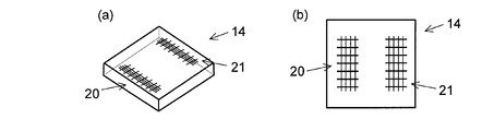
- the perspective view (a) and top view (b) which show the window part used for the blood glucose level sensor which concerns on 2nd Example of this invention.
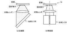
- the front view (a) and side view (b) which show the 1st-order diffracted light from a diffraction grating. Schematic which shows the whole structure of the blood glucose level sensor which concerns on 3rd Example of this invention.
- FIG. 1 shows the overall configuration of a blood glucose level sensor 10 according to the present embodiment.
- the blood glucose level sensor 10 includes a rectangular box-shaped casing 12, a rectangular plate-like window 14 fixed to one of the outer peripheral side surfaces of the casing 12, for example, an upper surface, and a spectroscopic measurement unit 16 accommodated in the casing 12. It consists of and.
- the casing 12 is made of a material that does not transmit light, such as plastic or metal.
- the window part 14 is produced from the material which has a light transmittance, and the fingertip which is a measuring object is mounted in the upper surface so that it may mention later. Therefore, the upper surface of the window part 14 becomes a mounting surface.
- a diffraction grating is formed on a part of the light irradiation surface which is the lower surface of the window portion 14 located in the casing 12. In this embodiment, two diffraction gratings 20 and 21 extending along two opposing sides of the window portion 14 are formed.
- a region where the two diffraction gratings 20 and 21 are formed on the light irradiation surface of the window portion 14 is also referred to as a reference light region, and the other region is also referred to as a measurement light region.
- Each of the diffraction gratings 20 and 21 is composed of a plurality of protrusions parallel to two sides. In this embodiment, the interval between the protrusions is set to 1.1 ⁇ m.
- the spectroscopic measurement unit 16 includes a light source 161, an objective lens 162, a phase shifter 163, an imaging lens 164, and a detection unit 165.
- the objective lens 162 and the imaging lens 164 correspond to an incident optical system and an imaging optical system, respectively.
- the objective lens 162 is disposed opposite to the light irradiation surface of the window portion 14.
- the imaging lens 164 is arranged in a direction in which the optical axis is orthogonal to the objective lens 162.
- the light source 161 uses a light source that emits near-infrared light having a good skin permeability and a wavelength of around 1 ⁇ m.
- the specularly reflected light is used.
- the first-order diffracted light generated when the diffraction gratings 20 and 21 are incident on the objective lens 162 is not incident on the objective lens 162.
- the first-order diffracted light from the diffraction gratings 20 and 21 is used as reference light. Therefore, in this embodiment, the light source 161 and the diffraction gratings 20 and 21 constitute reference light incident means.
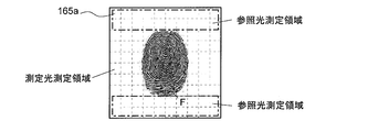
- the detection unit 165 includes, for example, a 16 ⁇ 16 pixel two-dimensional CCD (Charge Coupled Device) camera, and is arranged so that the light receiving surface 165 a of the detection unit 165 is positioned on the imaging surface of the imaging lens 164. .
- CCD Charge Coupled Device
- FIG. 2 is a diagram schematically showing the light receiving surface 165a of the detection unit 165.
- the number of pixels is described as 10 ⁇ 10 for convenience.
- a large number of pixels are arranged on the light receiving surface 165a of the detection unit 165.
- the diffraction grating 20 and the diffraction grating 20 are respectively formed on the upper 20 pixels (2 ⁇ 10) and the lower 20 pixels.
- First-order diffracted light (reference light) generated by the grating 21 forms an image. Accordingly, these pixels serve as a reference light detection unit.
- the reference light detection unit may be 16 pixels excluding a total of four pixels, two pixels located on both the left and right sides of the upper end and the lower end.
- the measurement light is imaged on the pixels of the light receiving surface 165a excluding the reference light detection unit. Accordingly, these pixels serve as the measurement light detection unit of the present invention. Actually, the measurement light forms an image on the pixel located at the portion indicated by the image F of the fingertip placed on the placement surface of the window portion 14.
- the detection signal of the detection unit 165 is input to the processing unit 42.
- the processing unit 42 obtains an interferogram from the detection signal from the detection unit 165.
- This interferogram is mathematically Fourier transformed by the arithmetic processing unit 43, and as a result, a spectral characteristic (spectrum) that is a relative intensity for each wavelength of the measurement light is obtained.
- the phase shifter 163 is disposed between the objective lens 162 and the imaging lens 164.
- the phase shifter 163 includes a fixed mirror unit 31, a movable mirror unit 32, and a drive mechanism 33 that moves the movable mirror unit 32.
- the fixed mirror unit 31 and the movable mirror unit 32 correspond to the fixed reflection unit and the movable reflection unit of the present invention, respectively.
- Both the fixed mirror unit 31 and the movable mirror unit 32 have a rectangular reflecting surface that is inclined at an angle of 45 ° with respect to the optical axis of the objective lens 162 and the optical axis of the imaging lens 164.
- the reflecting surfaces of both mirror parts are arranged side by side with a very slight gap.
- the drive mechanism 33 is composed of, for example, a piezoelectric element having a capacitance sensor, receives a signal from the control unit 40, and maintains a tilt angle of the reflecting surface with respect to the optical axis at 45 ° while moving the mirror unit. 32 is moved in the direction of arrow A. With such a configuration, the relative position of the movable mirror unit 32 with respect to the fixed mirror unit 31 changes, and a phase difference is given between the light beam reflected by the fixed mirror unit 31 and the light beam reflected by the movable mirror unit 32. .
- the moving amount of the objective lens 162 or the imaging lens 164 of the movable mirror unit 32 in the optical axis direction is 1 / ⁇ 2 of the moving amount of the movable mirror unit 32 in the arrow A direction.
- the optical path length difference that gives a relative phase change between the fixed light beam and the movable light beam is twice the amount of movement of the movable mirror portion 32 in the optical axis direction.
- the fingertip of the subject's hand is placed on the placement surface of the window portion 14.
- the fingertip is not only placed on the placement surface of the window portion 14 but also strongly pressed against the placement surface.
- the focus position of the objective lens 162 can be maintained at a predetermined position (depth) inside the fingertip during measurement.
- the fingertip does not necessarily have to be pressed down strongly. For example, when detecting a component in a blood vessel in a region close to the surface of the fingertip, the fingertip may be lightly placed on the placement surface.
- the light irradiation surface of the window part 14 is irradiated with near infrared light from the light source 161 with the fingertip pressed against the mounting surface of the window part 14. Then, the near-infrared light irradiated to the measurement light area
- Scattered light as measurement light emitted from the inside of the fingertip reaches the objective lens 162 while spreading in various directions, becomes a parallel light beam, and reaches the entire surfaces of the fixed mirror portion 31 and the movable mirror portion 32 of the phase shifter 163. That is, a part of the scattered light is reflected by the reflecting surface of the fixed mirror unit 31, and the remaining scattered light is reflected by the reflecting surface of the movable mirror unit 32 and enters the imaging lens 164.
- the scattered light reflected by the fixed mirror unit 31 is also called a fixed scattered light beam
- the scattered light reflected by the movable mirror unit 32 is also called a movable scattered light beam.
- the fixed scattered light beam and the movable scattered light beam incident on the imaging lens 164 are imaged on the light receiving surface 165a of the detection unit 165 to form an interference image.
- the movable mirror unit 32 is moved to change the optical path length difference between the movable scattered light beam and the fixed scattered light beam.
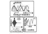
- Spectral characteristics can be obtained by mathematically Fourier transforming the interferogram.
- FIG. 3 shows changes in interference intensity (a), interferogram (b), and spectral characteristics (c) of light of each wavelength.
- the blood glucose level sensor 10 of the present embodiment only the scattered light emitted from the focusing surface located at a specific depth of the objective lens 162 within the fingertip is imaged on the light receiving surface 165a of the detection unit 165 and focused. Light generated from other than the surface does not form an image on the light receiving surface 165a of the detection unit 165. Accordingly, it is possible to obtain the spectral characteristics inside the fingertip with the depth limited only to the in-focus surface.
- near-infrared light irradiated on the reference light region of the window portion 14 is reflected by the diffraction gratings 20 and 21.
- the specularly reflected light (light indicated by the symbol “L0” in FIG. 1) irradiated from the light source 161 to the light irradiation surface of the window portion 14 does not enter the objective lens 162.
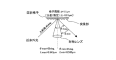
- first-order diffracted light having a specific wavelength ⁇ determined by the numerical aperture of the objective lens 162, the grating period of the diffraction gratings 20 and 21 (interval of the protrusions), the incident angle ⁇ in, and the outgoing angle ⁇ out is incident on the objective lens 162.
- near infrared light from the light source 161 is incident at an incident angle of 45 deg.
- the minimum diffraction angle ⁇ min on the short wavelength side incident on the objective lens 162 is 31 deg.
- the wavelength ⁇ min is 0.566 ⁇ m
- the maximum diffraction angle ⁇ max on the long wavelength side is 59 deg.
- the wavelength ⁇ max is 0.943 ⁇ m.
- an InGaAs camera having a detection wavelength range of 0.9 ⁇ m to 1.7 ⁇ m is used as the detection unit 165. Therefore, of the first-order diffracted light incident on the objective lens 162, the wavelength range detected by the detection unit 165 is a very narrow wavelength range (0.9 ⁇ m to 0.943 ⁇ m).
- the first-order diffracted light from the diffraction gratings 20 and 21 spreads in the width direction of the diffraction gratings 20 and 21 and reaches the objective lens 162 (see the front view of FIG. 5A). In the direction in which the diffraction gratings 20 and 21 extend, it reaches the objective lens 162 as a parallel light beam (see the side view of FIG. 5B). That is, the first-order diffracted light having a truncated pyramid shape as shown in FIG. 5C reaches the objective lens 162.
- the first-order diffracted light that has entered the objective lens 162 reaches a band-like light having a width equivalent to the size of the light source 161 near the boundary between the fixed mirror unit 31 and the movable mirror unit 32, and a part thereof is the fixed mirror unit.
- the light is reflected by the reflecting surface 31, and the rest is reflected by the reflecting surface of the movable mirror portion 32 and enters the imaging lens 164.
- the first-order diffracted light reflected by the fixed mirror unit 31 is also called fixed diffracted light
- the first-order diffracted light reflected by the movable mirror unit 32 is also called movable diffracted light.
- the fixed diffracted light and the movable diffracted light incident on the image forming lens 164 are imaged on the light receiving surface 165a of the detecting unit 165 to form an interference image.
- the interference light intensity change can be obtained by moving the movable mirror 32 to change the optical path length difference between the fixed diffracted light and the movable diffracted light.
- the fixed diffracted light and the movable diffracted light have a very narrow wavelength range and can be said to be light of almost a single wavelength. Therefore, the shape of the interference light intensity change obtained here is a simple cosine wave.
- the light emitted to the fingertip through the window portion 14 and the light that generates the first-order diffracted light by the diffraction gratings 20 and 21 are light emitted from the same light source, and thus the light intensity emitted from the light source 161 fluctuated.
- both the interference light intensity change of the measurement light (scattered light) and the interference light intensity change of the first-order diffracted light are affected.
- the optical path of the measurement light and the first-order diffracted light from the window section 14 to the detection section 165 is common, when disturbance occurs on this common optical path, the interference light intensity change of the measurement light and the first-order diffracted light Both changes in interference light intensity are affected by disturbances.
- the arithmetic processing unit 43 of the present embodiment determines the interferogram of the measurement light from the amplitude of the interference light intensity change of the first-order diffracted light and the phase difference between the first-order diffracted light and the measurement light having the same wavelength as the first-order diffracted light. Is corrected, and the corrected interferogram is Fourier transformed to obtain the spectral characteristics. For example, if the interferogram of the measurement light as shown in FIG. 6A and the interference light intensity change of the diffracted light as shown in FIG. 6B are obtained, the interference of the interferogram of the measurement light The interferogram is corrected by using the ratio of the light intensity to the amplitude of the interference light intensity change of the first-order diffracted light.
- the interferogram is corrected by shifting the phase of the interferogram of the measurement light by the phase shift amount between the first-order diffracted light and the measurement light.
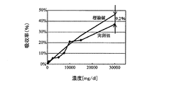
- FIG. 7 shows the results of measuring the glucose concentration in the test tube using the blood glucose level sensor 10 of this example. As shown in FIG. 7, although it did not completely coincide with the theoretical value, the absorption rate tended to increase depending on the concentration, and a good correlation between the glucose concentration and the absorption rate was obtained. Moreover, although the glucose concentration in the blood of a general human is about 100 mg / dl, it turned out that a glucose concentration is detectable even in such a low concentration.
- FIG. 8 shows the configuration of the window 14 used in the blood glucose level sensor 10 according to the second embodiment of the present invention.
- the diffraction gratings 20 and 21 provided on the light irradiation surface of the window portion 14 include a first ridge portion parallel to one side of the window portion 14 and a second ridge perpendicular to the ridge portion. It differs from the first embodiment in that it is composed of strips.
- the interval between the first protrusions was the same as that of the diffraction grating of the first example.
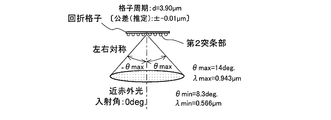
- the distance between the second protrusions (diffraction period) d 3.9 ⁇ m.
- the numerical aperture of the objective lens 161, the focal length, the lens aperture, and the incident direction of the near-infrared light from the light source 161 to the light irradiation surface are the same as in the first embodiment. Therefore, the same first-order diffracted light as that in the first embodiment is generated from the first protrusion.
- the near infrared light is incident on the second protrusion at an incident angle of 0 deg. .
- first-order diffracted light that is symmetric with respect to the incident light is emitted from the second protrusions of the diffraction gratings 20 and 21.
- the minimum diffraction angle ⁇ min on the short wavelength side incident on the objective lens 162 is ⁇ 8.3 deg.
- the wavelength ⁇ min of the first-order diffracted light is 0.566 ⁇ m
- the maximum diffraction angle ⁇ max on the long wavelength side is ⁇ 14 deg.
- the wavelength ⁇ max of the first-order diffracted light is 0.943 ⁇ m. Therefore, also for the first-order diffracted light at the second protrusion, the wavelength range detected by the detection unit 165 including an InGaAs camera with a detection wavelength range of 0.9 ⁇ m to 1.7 ⁇ m is 0.9 ⁇ m to 0.943 ⁇ m.
- the first-order diffracted light from the diffraction gratings 20 and 21 extends both the first and second protrusions of the diffraction gratings 20 and 21. It spreads in the direction and reaches the objective lens 162.
- the first-order diffracted light incident on the objective lens 162 is wider than the blood glucose level sensor 10 of the first embodiment and reaches the boundary portion between the fixed mirror portion 31 and the movable mirror portion 32. For this reason, the first-order diffracted light is easily divided into two. Further, the light intensity of the first-order diffracted light can be increased as compared with the first embodiment.
- FIG. 11 shows a blood glucose level sensor 50 according to a third embodiment of the present invention.
- the third embodiment is different from the first embodiment in that laser light is used as reference light instead of the first-order diffracted light.
- reflection films 52 and 53 are provided on the light irradiation surface of the window portion 14 in place of the diffraction grating.
- a laser light source 54 is arranged in the casing 12 side by side with the light source 161, and light from the laser light source 54 is incident on the reflection film 52 of the window portion 14 through a lens 55, a mirror 56 and a beam splitter 57. It is like that.
- the laser light source 54 emits a narrow band laser beam (single wavelength laser beam) which is a part of the wavelength band of the light emitted from the light source 161.
- the single-wavelength laser light from the laser light source 54 that has entered the reflective film 52 is reflected by the reflective film 52, is incident on the objective lens 162, and is used as reference light.
- the near infrared light from the light source 161 is incident on the reflective film 53 and the areas other than the reflective films 52 and 53 on the light irradiation surface of the window portion 14.
- Near-infrared light from the light source 161 that has entered a region other than the reflective films 52 and 53 on the light irradiation surface reaches the fingertip through the window 14 and is scattered by various biological components inside the fingertip. This scattered light passes through the skin of the fingertip as measurement light, enters the casing 12 from the window portion 14, and enters the objective lens 162.
- near-infrared light from the light source 161 that has entered the reflective film 53 is reflected by the reflective film 53, enters the objective lens 162, and is used as reference light.
- the laser light emitted from the laser light source 54 is also set to a weak intensity in accordance with the scattered light.
- the laser light reflected by the reflective film 52 and incident on the objective lens 162 and the near-infrared light reflected by the reflective film 53 and incident on the objective lens 162 are respectively two by the phase shifter 163.
- the light enters the imaging lens 164.
- the laser light incident on the imaging lens 164 is condensed at substantially the same point on the light receiving surface 165a of the detector 165 and interferes therewith.
- the near-infrared light incident on the imaging lens 164 forms an image on the light receiving surface 165a of the detection unit 165 to form an interference image.
- the interference light intensity change can be obtained for each of the laser light and the near-infrared light as the reference light. Since the laser light has a single wavelength, the interference light intensity change is a simple cosine wave as in the first-order diffracted light described in the first embodiment. Since the optical path of the measurement light (scattered light) from the window section 14 to the detection section 165 is the same as the optical path of the laser light, if a disturbance occurs on this common optical path, the change in the interference light intensity of the measurement light and the laser light Both are affected by disturbances. Therefore, in this embodiment, the interferogram of the measurement light is corrected from the amplitude of the interference light intensity change of the laser light and the phase difference of the measurement light of the laser light. Thereby, the influence of the disturbance on an optical path can be suppressed.
- the reflected light of the near infrared light by the reflective film 53 has multiple wavelengths like the measurement light (scattered light), and therefore the interference light intensity change becomes an interferogram.
- Both the measurement light and the reflected light from the reflective film 53 are affected by fluctuations in the light intensity of the light source 161.
- the measurement light and the reflected light from the reflection film 53 have a common optical path from the window portion 14 to the detection portion 165, when a disturbance occurs on this common optical path, the measurement light and the reflection film 53 Both reflected lights are affected by disturbances. Therefore, in this embodiment, the phase and intensity of the interferogram of scattered light are corrected using the phase and intensity of the interferogram of reflected light.
- the influence of the disturbance on an optical path and the influence of the fluctuation of the light of the light source 161 can be suppressed.
- the interferogram of the measurement light can be obtained with higher accuracy.
- this invention is not limited to the above-mentioned Example, A suitable change is possible.
- a drive mechanism that moves the objective lens in the optical axis direction may be provided. If comprised in this way, the focus position of an objective lens, ie, the depth of the measurement point inside a measuring object, can be changed.
- the present invention can also be applied to an apparatus for detecting the presence or absence of minute defects or foreign matters on a substrate from the spectral characteristics of reflected light (measurement light) emitted from the substrate such as a semiconductor when the substrate is irradiated with light.
- a reflecting plate obtained by mirror-polishing the surface of a stainless steel plate or a reflecting plate obtained by coating a surface of a glass substrate with a metal film such as aluminum can be used.
- the present invention can also be applied to a Fourier transform infrared spectrophotometer (FT-IR) in which an interferogram is measured using a Michelson interferometer and a spectrum (spectral characteristic) is obtained by performing Fourier transform on the interferogram. is there.
- FT-IR Fourier transform infrared spectrophotometer
- the interferogram is corrected using one reference beam, but a plurality of reference beams may be used.
Landscapes
- Physics & Mathematics (AREA)
- Spectroscopy & Molecular Physics (AREA)
- Health & Medical Sciences (AREA)
- Life Sciences & Earth Sciences (AREA)
- General Physics & Mathematics (AREA)
- General Health & Medical Sciences (AREA)
- Pathology (AREA)
- Immunology (AREA)
- Biochemistry (AREA)
- Analytical Chemistry (AREA)
- Chemical & Material Sciences (AREA)
- Engineering & Computer Science (AREA)
- Biophysics (AREA)
- Molecular Biology (AREA)
- Surgery (AREA)
- Animal Behavior & Ethology (AREA)
- Medical Informatics (AREA)
- Public Health (AREA)
- Veterinary Medicine (AREA)
- Heart & Thoracic Surgery (AREA)
- Biomedical Technology (AREA)
- Optics & Photonics (AREA)
- Emergency Medicine (AREA)
- Mathematical Physics (AREA)
- Artificial Intelligence (AREA)
- Computer Vision & Pattern Recognition (AREA)
- Physiology (AREA)
- Psychiatry (AREA)
- Signal Processing (AREA)
- Investigating Or Analysing Materials By Optical Means (AREA)
Description
血液中の血糖(グルコース)やコレステロール等の生体成分の濃度値は、血管に光を照射してそれを透過した光、又は、反射した光の中の、それら特定成分が吸収又は反射する(1又は複数の)特定波長の光の強度を測定することにより求めることができる。しかし従来の方法では、光源光量の変化や温度・湿度等の周囲環境の変化、可動ミラー部の移動誤差等の外乱によって測定光の強度が変化してしまい、特定成分の濃度を高精度に測定することができないという問題があった。
このような問題は、半導体基板に光を照射したときに該半導体基板から発せられる光の分光特性から、半導体基板の微小な欠陥を検出する場合等にも生じる。
a)固定反射部及び可動反射部と、
b)測定対象から発せられた測定光を前記固定反射部と前記可動反射部に入射させる入射光学系と、
c)前記固定反射部によって反射された測定光と前記可動反射部によって反射された測定光の干渉光を形成する結像光学系と、
d)前記測定光の干渉光強度を検出する測定光検出部と、
e)前記可動反射部を移動させることにより得られる前記測定光の干渉光強度変化に基づき前記測定光のインターフェログラムを求める処理部と、
f)前記測定光の波長帯域の一部である狭帯域の波長の参照光を、前記入射光学系を通して前記固定反射部と前記可動反射部に入射させる参照光入射手段と、
g)前記固定反射部によって反射された参照光と前記可動反射部によって反射された参照光の、前記結像光学系によって形成される干渉光強度を検出する参照光検出部と、
h)前記可動反射部を移動させることにより前記参照光検出部で検出される前記参照光の干渉光強度変化の振幅、及び前記測定光のうち前記参照光と同じ波長の測定光と前記参照光の位相差に基づき前記測定光のインターフェログラムを補正し、補正後のインターフェログラムに基づき前記測定光のスペクトルを求める演算処理部と
を備えることを特徴とする。
前記参照光入射手段を、光源と、該光源から出射された光の1次回折光を参照光として前記入射光学系に入射させる反射型の回折格子とから構成することができる。
前記回折格子が、前記光照射面の一部の領域に設けられ、
前記光源が、前記光照射面の全体に光を照射し、且つ、該光照射面に光が照射されたときに発生する正反射光が前記入射光学系に入射しない角度で該光照射面に光を照射するように構成すると良い。
また、上記構成では、光源からの光を窓部の光照射面に照射させたときに生じる正反射光(0次光)は入射光学系に入射せず、1次回折光を参照光として入射光学系に入射させた。正反射光に比べると1次回折光成分の光量は非常に小さいが、該1次回折光と同様に目的成分から発する散乱光成分の光量も非常に小さいため、測定光と参照光のバランスをとることができる。
前記参照光入射手段を、前記測定光の波長帯域の一部である狭帯域の光を出射する光源と、前記光源から出射された光を反射して前記入射光学系に入射させる反射膜とから構成することもできる。
a)測定対象から発せられた測定光を入射光学系によって固定反射部と可動反射部に入射させ、
b)前記固定反射部によって反射された測定光と前記可動反射部によって反射された測定光の干渉光を形成させ、
c)前記可動反射部を移動させることにより得られる前記測定光の干渉光強度変化に基づき前記測定光のインターフェログラムを求め、
d)前記測定光の波長帯域の一部である狭帯域の波長の参照光を、前記入射光学系を通して固定反射部及び可動反射部に入射させ、
e)前記固定反射部によって反射された参照光と前記可動反射部によって反射された参照光の干渉光強度を検出し、
f)前記可動反射部を移動させることにより得られる参照光の干渉光強度変化の振幅、及び前記測定光のうち前記参照光と同じ波長の測定光と前記参照光の位相差に基づき前記測定点のインターフェログラムを補正し、補正後のインターフェログラムに基づき前記測定光のスペクトルを求めることを特徴とする。
光源から回折格子に照射することにより該回折格子において生じる1次回折光を参照光として前記入射光学系に入射させると良い。
前記光源が、前記光照射面の全体に光を照射し、且つ、前記光照射面に光が照射されたときに発生する正反射光が前記入射光学系に入射しない角度で該光照射面に光を照射するようにすると良い。
検出部165は例えば16×16画素の二次元CCD(Charge Coupled Device)カメラから構成されており、結像レンズ164の結像面に検出部165の受光面165aが位置するように配置されている。
まず、被検者の手の指先を窓部14の載置面に載置する。ここでは、指先を窓部14の載置面に載置するだけでなく、載置面に強く押し当てることとする。このように、強く押し当てることにより、測定中、対物レンズ162の合焦位置を、指先の内部の所定の位置(深度)に維持することができる。なお、指先は必ずしも強く押さえつけなければならないものではなく、例えば指先の表面に近い領域の血管中の成分等を検出する場合には載置面上に軽く乗せる程度としてもよい。
また、本実施例の血糖値センサ10では、指先内部のうち対物レンズ162の特定深度に位置する合焦面から発せられた散乱光のみが検出部165の受光面165aにおいて結像し、合焦面以外から生じた光は検出部165の受光面165aで結像しない。従って、合焦面のみに深度を限定した指先内部の分光特性を得ることができる。
このように、本実施例では、光源161からの光及びレーザ光源54からの光の両方を参照光として用いたため、測定光のインターフェログラムを一層精度良く求めることができる。
12…ケーシング
14…窓部
16…分光測定部
161…光源
162…対物レンズ
163…位相シフタ
164…結像レンズ
165…検出部
165a…受光面
20、21…回折格子
31…固定ミラー部
32…可動ミラー部
33…駆動機構
40…制御部
42…処理部
43…演算処理部
52…反射膜
Claims (8)
- a)固定反射部及び可動反射部と、
b)測定対象から発せられた測定光を前記固定反射部と前記可動反射部に入射させる入射光学系と、
c)前記固定反射部によって反射された測定光と前記可動反射部によって反射された測定光の干渉光を形成する結像光学系と、
d)前記測定光の干渉光強度を検出する測定光検出部と、
e)前記可動反射部を移動させることにより得られる前記測定光の干渉光強度変化に基づき前記測定光のインターフェログラムを求める処理部と、
f)前記測定光の波長帯域の一部である狭帯域の波長の参照光を、前記入射光学系を通して前記固定反射部と前記可動反射部に入射させる参照光入射手段と、
g)前記固定反射部によって反射された参照光と前記可動反射部によって反射された参照光の、前記結像光学系によって形成される干渉光強度を検出する参照光検出部と、
h)前記可動反射部を移動させることにより前記参照光検出部で検出される前記参照光の干渉光強度変化の振幅、及び前記測定光のうち前記参照光と同じ波長の測定光と前記参照光の位相差に基づき前記測定光のインターフェログラムを補正し、補正後のインターフェログラムに基づき前記測定光のスペクトルを求める演算処理部と
を備えることを特徴とする分光特性測定装置。 - 請求項1に記載の分光特性測定装置において、
前記参照光入射手段が、
光源と、
該光源から出射された光の1次回折光を参照光として前記入射光学系に入射させる反射型の回折格子と
から構成されていることを特徴とする分光特性測定装置。 - 請求項2に記載の分光特性測定装置において、
光透過性部材から成る板状の窓部であって、その両面のうちの一方が前記測定対象が載置される載置面であり、他方が光照射面である窓部を備え、
前記回折格子が、前記光照射面の一部の領域に設けられ、
前記光源が、前記光照射面の全体に光を照射し、且つ、該光照射面に光が照射されたときに発生する正反射光が前記入射光学系に入射しない角度で該光照射面に光を照射するものであることを特徴とする分光特性測定装置。 - 請求項1に記載の分光特性測定装置において、
前記参照光入射手段が、
前記測定光の波長帯域の一部である狭帯域の光を出射する光源と、
前記光源から出射された光を反射して前記入射光学系に入射させる反射膜と
から構成されていることを特徴とする分光特性測定装置。 - a)測定対象から発せられた測定光を入射光学系によって固定反射部と可動反射部に入射させ、
b)前記固定反射部によって反射された測定光と前記可動反射部によって反射された測定光の干渉光を形成させ、
c)前記可動反射部を移動させることにより得られる前記測定光の干渉光強度変化に基づき前記測定光のインターフェログラムを求め、
d)前記測定光の波長帯域の一部である狭帯域の波長の参照光を、前記入射光学系を通して固定反射部及び可動反射部に入射させ、
e)前記固定反射部によって反射された参照光と前記可動反射部によって反射された参照光の干渉光強度を検出し、
f)前記可動反射部を移動させることにより得られる参照光の干渉光強度変化の振幅、及び前記測定光のうち前記参照光と同じ波長の測定光と前記参照光の位相差に基づき前記測定点のインターフェログラムを補正し、補正後のインターフェログラムに基づき前記測定光のスペクトルを求めることを特徴とする分光特性測定方法。 - 請求項5に記載の分光特性測定方法において、
光源からの光を回折格子に照射することにより該回折格子において生じる1次回折光を参照光として前記入射光学系に入射させることを特徴とする分光特性測定方法。 - 請求項6に記載の分光特性測定方法において、
光透過性部材から成る板状の窓部であって、その両面のうちの一方が前記測定対象が載置される載置面であり、他方の面が光照射面である窓部の、該光照射面の一部の領域に前記回折格子を設け、
前記光源が、前記光照射面の全体に光を照射し、且つ、該光照射面に光が照射されたときに発生する正反射光が前記入射光学系に入射しない角度で該光照射面に光を照射することを特徴とする分光特性測定方法。 - 請求項5に記載の分光特性測定方法において、
前記測定光の波長帯域の一部である狭帯域の光を光源から反射膜に照射し、該反射膜で反射された光を参照光として前記入射光学系に入射させることを特徴とする分光特性測定方法。
Priority Applications (7)
| Application Number | Priority Date | Filing Date | Title |
|---|---|---|---|
| EP13754598.4A EP2821777B1 (en) | 2012-02-29 | 2013-02-27 | Spectral characteristics measurement device and method for measuring spectral characteristics |
| CA2866019A CA2866019C (en) | 2012-02-29 | 2013-02-27 | Spectral characteristics measurement device and spectral characteristics measurement method |
| US14/380,643 US9474476B2 (en) | 2012-02-29 | 2013-02-27 | Spectral characteristics measurement device and spectral characteristics measurement method |
| RU2014138805/28A RU2575946C1 (ru) | 2012-02-29 | 2013-02-27 | Устройство измерения спектральных характеристик и способ измерения спектральных характеристик |
| CN201380011702.3A CN104145177B (zh) | 2012-02-29 | 2013-02-27 | 分光特性测量装置以及分光特性测量方法 |
| JP2014502333A JP5637488B2 (ja) | 2012-02-29 | 2013-02-27 | 分光特性測定装置及び分光特性測定方法 |
| KR1020147023627A KR101627444B1 (ko) | 2012-02-29 | 2013-02-27 | 분광 특성 측정 장치 및 분광 특성 측정 방법 |
Applications Claiming Priority (2)
| Application Number | Priority Date | Filing Date | Title |
|---|---|---|---|
| JP2012044272 | 2012-02-29 | ||
| JP2012-044272 | 2012-02-29 |
Publications (1)
| Publication Number | Publication Date |
|---|---|
| WO2013129519A1 true WO2013129519A1 (ja) | 2013-09-06 |
Family
ID=49082713
Family Applications (1)
| Application Number | Title | Priority Date | Filing Date |
|---|---|---|---|
| PCT/JP2013/055228 Ceased WO2013129519A1 (ja) | 2012-02-29 | 2013-02-27 | 分光特性測定装置及び分光特性測定方法 |
Country Status (8)
| Country | Link |
|---|---|
| US (1) | US9474476B2 (ja) |
| EP (1) | EP2821777B1 (ja) |
| JP (1) | JP5637488B2 (ja) |
| KR (1) | KR101627444B1 (ja) |
| CN (1) | CN104145177B (ja) |
| CA (1) | CA2866019C (ja) |
| RU (1) | RU2575946C1 (ja) |
| WO (1) | WO2013129519A1 (ja) |
Cited By (3)
| Publication number | Priority date | Publication date | Assignee | Title |
|---|---|---|---|---|
| WO2015137880A1 (en) * | 2014-03-13 | 2015-09-17 | National University Of Singapore | An optical interference device |
| JPWO2023013574A1 (ja) * | 2021-08-03 | 2023-02-09 | ||
| JP2025032031A (ja) * | 2020-09-30 | 2025-03-07 | ライトタッチテクノロジー株式会社 | 血中物質濃度測定方法 |
Families Citing this family (14)
| Publication number | Priority date | Publication date | Assignee | Title |
|---|---|---|---|---|
| SG11201404625YA (en) * | 2012-02-21 | 2014-10-30 | Mc Professional Oü | A formula and method for monitoring individual metabolic response and for generating predictive medical metrics |
| JP5987573B2 (ja) * | 2012-09-12 | 2016-09-07 | セイコーエプソン株式会社 | 光学モジュール、電子機器、及び駆動方法 |
| JP6441759B2 (ja) * | 2015-07-24 | 2018-12-19 | 株式会社堀場製作所 | 分光分析器に用いられる光検出器の出力補正方法 |
| CN105596011B (zh) * | 2016-02-25 | 2018-11-20 | 中山北京理工大学研究院 | 一种无创血糖检测装置 |
| JP6818487B2 (ja) * | 2016-09-28 | 2021-01-20 | 花王株式会社 | スペクトルの測定方法 |
| KR102498122B1 (ko) | 2017-11-21 | 2023-02-09 | 삼성전자주식회사 | 분광 장치와, 분광 방법, 및 생체신호 측정장치 |
| JP6688917B1 (ja) * | 2019-01-30 | 2020-04-28 | 浜松ホトニクス株式会社 | 光モジュール、信号処理システム及び信号処理方法 |
| AU2020338951B2 (en) * | 2019-08-28 | 2025-12-18 | Foss Analytical A/S | Method of correcting for an amplitude change in a spectrometer |
| WO2022051210A1 (en) | 2020-09-03 | 2022-03-10 | Siemens Healthcare Diagnostics Inc. | Diagnostic analyzer having a dual-purpose imager |
| CN112958479A (zh) * | 2021-02-06 | 2021-06-15 | 厦门大学 | 一种柔性电路板焊盘检测分拣装置及其使用方法 |
| WO2023009840A1 (en) * | 2021-07-29 | 2023-02-02 | Si-Ware Systems | Compact spectral analyzer |
| KR20250049818A (ko) * | 2023-10-05 | 2025-04-14 | 현대자동차주식회사 | 조명장치용 고장 판단 시스템 |
| WO2025087898A1 (en) | 2023-10-23 | 2025-05-01 | Trinamix Gmbh | Spectrometer device for obtaining spectroscopic information on at least one object wherein the imaging plane of the imaging system is positioned at a distance from the illumination plane |
| KR102787937B1 (ko) | 2024-09-26 | 2025-03-31 | (주)휴마스 | 가변형 슬릿과 광로 길이가 가변되는 다단측정셀을 이용한 광도법 수질측정 장치 |
Citations (4)
| Publication number | Priority date | Publication date | Assignee | Title |
|---|---|---|---|---|
| JP2002514301A (ja) * | 1996-12-04 | 2002-05-14 | ザ・リサーチ・ファンデーション・オブ・シティ・ユニバーシティ・オブ・ニューヨーク | 選択的に光学的計測を行う装置及び方法 |
| JP2002286410A (ja) * | 2001-03-26 | 2002-10-03 | Fuji Photo Optical Co Ltd | 干渉計装置 |
| JP2008309707A (ja) | 2007-06-15 | 2008-12-25 | Kagawa Univ | 分光計測装置及び分光計測方法 |
| JP2008309706A (ja) * | 2007-06-15 | 2008-12-25 | Kagawa Univ | 分光計測装置及び分光計測方法 |
Family Cites Families (7)
| Publication number | Priority date | Publication date | Assignee | Title |
|---|---|---|---|---|
| US6437867B2 (en) * | 1996-12-04 | 2002-08-20 | The Research Foundation Of The City University Of New York | Performing selected optical measurements with optical coherence domain reflectometry |
| US6624894B2 (en) * | 2001-06-25 | 2003-09-23 | Veeco Instruments Inc. | Scanning interferometry with reference signal |
| US7006232B2 (en) * | 2002-04-05 | 2006-02-28 | Case Western Reserve University | Phase-referenced doppler optical coherence tomography |
| RU2307318C1 (ru) * | 2005-12-19 | 2007-09-27 | Петр Витальевич Волков | Интерферометрическое измерительное устройство (варианты) |
| JP5358890B2 (ja) * | 2007-03-20 | 2013-12-04 | 株式会社島津製作所 | 干渉分光光度計 |
| JP5510712B2 (ja) * | 2010-02-22 | 2014-06-04 | 株式会社ニコン | 非線形顕微鏡 |
| GB201011459D0 (en) * | 2010-07-07 | 2010-08-25 | Melys Diagnostics Ltd | Optical element, assembly and method for determining analyte concentration |
-
2013
- 2013-02-27 US US14/380,643 patent/US9474476B2/en active Active
- 2013-02-27 RU RU2014138805/28A patent/RU2575946C1/ru not_active IP Right Cessation
- 2013-02-27 EP EP13754598.4A patent/EP2821777B1/en not_active Not-in-force
- 2013-02-27 CN CN201380011702.3A patent/CN104145177B/zh not_active Expired - Fee Related
- 2013-02-27 WO PCT/JP2013/055228 patent/WO2013129519A1/ja not_active Ceased
- 2013-02-27 CA CA2866019A patent/CA2866019C/en not_active Expired - Fee Related
- 2013-02-27 JP JP2014502333A patent/JP5637488B2/ja active Active
- 2013-02-27 KR KR1020147023627A patent/KR101627444B1/ko not_active Expired - Fee Related
Patent Citations (4)
| Publication number | Priority date | Publication date | Assignee | Title |
|---|---|---|---|---|
| JP2002514301A (ja) * | 1996-12-04 | 2002-05-14 | ザ・リサーチ・ファンデーション・オブ・シティ・ユニバーシティ・オブ・ニューヨーク | 選択的に光学的計測を行う装置及び方法 |
| JP2002286410A (ja) * | 2001-03-26 | 2002-10-03 | Fuji Photo Optical Co Ltd | 干渉計装置 |
| JP2008309707A (ja) | 2007-06-15 | 2008-12-25 | Kagawa Univ | 分光計測装置及び分光計測方法 |
| JP2008309706A (ja) * | 2007-06-15 | 2008-12-25 | Kagawa Univ | 分光計測装置及び分光計測方法 |
Non-Patent Citations (1)
| Title |
|---|
| See also references of EP2821777A4 |
Cited By (5)
| Publication number | Priority date | Publication date | Assignee | Title |
|---|---|---|---|---|
| WO2015137880A1 (en) * | 2014-03-13 | 2015-09-17 | National University Of Singapore | An optical interference device |
| US10760971B2 (en) | 2014-03-13 | 2020-09-01 | National University Of Singapore | Optical interference device |
| JP2025032031A (ja) * | 2020-09-30 | 2025-03-07 | ライトタッチテクノロジー株式会社 | 血中物質濃度測定方法 |
| JP7762457B2 (ja) | 2020-09-30 | 2025-10-30 | ライトタッチテクノロジー株式会社 | 血中物質濃度測定方法 |
| JPWO2023013574A1 (ja) * | 2021-08-03 | 2023-02-09 |
Also Published As
| Publication number | Publication date |
|---|---|
| RU2575946C1 (ru) | 2016-02-27 |
| US20150043001A1 (en) | 2015-02-12 |
| JP5637488B2 (ja) | 2014-12-10 |
| CA2866019A1 (en) | 2013-09-06 |
| CN104145177B (zh) | 2016-07-06 |
| EP2821777B1 (en) | 2015-10-21 |
| EP2821777A1 (en) | 2015-01-07 |
| KR20140114447A (ko) | 2014-09-26 |
| US9474476B2 (en) | 2016-10-25 |
| CA2866019C (en) | 2017-06-27 |
| CN104145177A (zh) | 2014-11-12 |
| JPWO2013129519A1 (ja) | 2015-07-30 |
| KR101627444B1 (ko) | 2016-06-03 |
| EP2821777A4 (en) | 2015-01-21 |
Similar Documents
| Publication | Publication Date | Title |
|---|---|---|
| JP5637488B2 (ja) | 分光特性測定装置及び分光特性測定方法 | |
| JP5765693B2 (ja) | 分光特性測定装置 | |
| KR101683407B1 (ko) | 분광 측정 장치 | |
| JP5317298B2 (ja) | 分光計測装置及び分光計測方法 | |
| CA2826737C (en) | Apparatus and method for optical coherence tomography | |
| KR20180036757A (ko) | 물질의 비접촉 감지를 위한 레퍼런스 스위치 아키텍처 | |
| JP4973750B2 (ja) | 成分測定装置 | |
| JP6744005B2 (ja) | 分光測定装置 | |
| JP2014025899A5 (ja) | ||
| WO2016121540A1 (ja) | 分光測定装置および分光測定方法 | |
| JP5577757B2 (ja) | 成分測定装置 |
Legal Events
| Date | Code | Title | Description |
|---|---|---|---|
| 121 | Ep: the epo has been informed by wipo that ep was designated in this application |
Ref document number: 13754598 Country of ref document: EP Kind code of ref document: A1 |
|
| ENP | Entry into the national phase |
Ref document number: 20147023627 Country of ref document: KR Kind code of ref document: A |
|
| WWE | Wipo information: entry into national phase |
Ref document number: 14380643 Country of ref document: US |
|
| ENP | Entry into the national phase |
Ref document number: 2014502333 Country of ref document: JP Kind code of ref document: A |
|
| ENP | Entry into the national phase |
Ref document number: 2866019 Country of ref document: CA |
|
| NENP | Non-entry into the national phase |
Ref country code: DE |
|
| WWE | Wipo information: entry into national phase |
Ref document number: 2013754598 Country of ref document: EP |
|
| WWE | Wipo information: entry into national phase |
Ref document number: 2014138805 Country of ref document: RU |