WO2013129550A1 - 発電装置 - Google Patents
発電装置 Download PDFInfo
- Publication number
- WO2013129550A1 WO2013129550A1 PCT/JP2013/055333 JP2013055333W WO2013129550A1 WO 2013129550 A1 WO2013129550 A1 WO 2013129550A1 JP 2013055333 W JP2013055333 W JP 2013055333W WO 2013129550 A1 WO2013129550 A1 WO 2013129550A1
- Authority
- WO
- WIPO (PCT)
- Prior art keywords
- expander
- generator
- storage box
- control device
- pedestal
- Prior art date
- Legal status (The legal status is an assumption and is not a legal conclusion. Google has not performed a legal analysis and makes no representation as to the accuracy of the status listed.)
- Ceased
Links
Images

Classifications
-
- F—MECHANICAL ENGINEERING; LIGHTING; HEATING; WEAPONS; BLASTING
- F01—MACHINES OR ENGINES IN GENERAL; ENGINE PLANTS IN GENERAL; STEAM ENGINES
- F01D—NON-POSITIVE DISPLACEMENT MACHINES OR ENGINES, e.g. STEAM TURBINES
- F01D15/00—Adaptations of machines or engines for special use; Combinations of engines with devices driven thereby
- F01D15/10—Adaptations for driving, or combinations with, electric generators
-
- F—MECHANICAL ENGINEERING; LIGHTING; HEATING; WEAPONS; BLASTING
- F01—MACHINES OR ENGINES IN GENERAL; ENGINE PLANTS IN GENERAL; STEAM ENGINES
- F01C—ROTARY-PISTON OR OSCILLATING-PISTON MACHINES OR ENGINES
- F01C13/00—Adaptations of machines or engines for special use; Combinations of engines with devices driven thereby
- F01C13/02—Adaptations of machines or engines for special use; Combinations of engines with devices driven thereby for driving hand-held tools or the like
-
- F—MECHANICAL ENGINEERING; LIGHTING; HEATING; WEAPONS; BLASTING
- F01—MACHINES OR ENGINES IN GENERAL; ENGINE PLANTS IN GENERAL; STEAM ENGINES
- F01C—ROTARY-PISTON OR OSCILLATING-PISTON MACHINES OR ENGINES
- F01C21/00—Component parts, details or accessories not provided for in groups F01C1/00 - F01C20/00
- F01C21/008—Driving elements, brakes, couplings, transmissions specially adapted for rotary or oscillating-piston machines or engines
-
- F—MECHANICAL ENGINEERING; LIGHTING; HEATING; WEAPONS; BLASTING
- F01—MACHINES OR ENGINES IN GENERAL; ENGINE PLANTS IN GENERAL; STEAM ENGINES
- F01C—ROTARY-PISTON OR OSCILLATING-PISTON MACHINES OR ENGINES
- F01C21/00—Component parts, details or accessories not provided for in groups F01C1/00 - F01C20/00
- F01C21/06—Heating; Cooling; Heat insulation
-
- F—MECHANICAL ENGINEERING; LIGHTING; HEATING; WEAPONS; BLASTING
- F01—MACHINES OR ENGINES IN GENERAL; ENGINE PLANTS IN GENERAL; STEAM ENGINES
- F01D—NON-POSITIVE DISPLACEMENT MACHINES OR ENGINES, e.g. STEAM TURBINES
- F01D25/00—Component parts, details, or accessories, not provided for in, or of interest apart from, other groups
- F01D25/28—Supporting or mounting arrangements, e.g. for turbine casing
-
- F—MECHANICAL ENGINEERING; LIGHTING; HEATING; WEAPONS; BLASTING
- F01—MACHINES OR ENGINES IN GENERAL; ENGINE PLANTS IN GENERAL; STEAM ENGINES
- F01K—STEAM ENGINE PLANTS; STEAM ACCUMULATORS; ENGINE PLANTS NOT OTHERWISE PROVIDED FOR; ENGINES USING SPECIAL WORKING FLUIDS OR CYCLES
- F01K13/00—General layout or general methods of operation of complete plants
- F01K13/02—Controlling, e.g. stopping or starting
-
- F—MECHANICAL ENGINEERING; LIGHTING; HEATING; WEAPONS; BLASTING
- F01—MACHINES OR ENGINES IN GENERAL; ENGINE PLANTS IN GENERAL; STEAM ENGINES
- F01C—ROTARY-PISTON OR OSCILLATING-PISTON MACHINES OR ENGINES
- F01C1/00—Rotary-piston machines or engines
- F01C1/02—Rotary-piston machines or engines of arcuate-engagement type, i.e. with circular translatory movement of co-operating members, each member having the same number of teeth or tooth-equivalents
-
- F—MECHANICAL ENGINEERING; LIGHTING; HEATING; WEAPONS; BLASTING
- F02—COMBUSTION ENGINES; HOT-GAS OR COMBUSTION-PRODUCT ENGINE PLANTS
- F02C—GAS-TURBINE PLANTS; AIR INTAKES FOR JET-PROPULSION PLANTS; CONTROLLING FUEL SUPPLY IN AIR-BREATHING JET-PROPULSION PLANTS
- F02C7/00—Features, components parts, details or accessories, not provided for in, or of interest apart form groups F02C1/00 - F02C6/00; Air intakes for jet-propulsion plants
- F02C7/36—Power transmission arrangements between the different shafts of the gas turbine plant, or between the gas-turbine plant and the power user
-
- F—MECHANICAL ENGINEERING; LIGHTING; HEATING; WEAPONS; BLASTING
- F04—POSITIVE - DISPLACEMENT MACHINES FOR LIQUIDS; PUMPS FOR LIQUIDS OR ELASTIC FLUIDS
- F04C—ROTARY-PISTON, OR OSCILLATING-PISTON, POSITIVE-DISPLACEMENT MACHINES FOR LIQUIDS; ROTARY-PISTON, OR OSCILLATING-PISTON, POSITIVE-DISPLACEMENT PUMPS
- F04C2230/00—Manufacture
- F04C2230/60—Assembly methods
- F04C2230/604—Mounting devices for pumps or compressors
Definitions
- the present invention relates to a technology of a power generation device, and in particular, includes an expander driven by steam, a generator driven by being connected to an output shaft of the expander, a control device, a pedestal, and a storage box. It relates to the technology of power generation equipment.
- a power generator including an expander that uses a working medium as water and a generator that is connected to and driven by the output shaft of the expander is known.
- the expander rotates the output shaft by expanding water (hereinafter simply referred to as “steam”), which is a high-temperature and high-pressure gas phase, in an expansion chamber formed by a fixed scroll and an orbiting scroll.
- steam expanding water
- the generator is connected to the output shaft and is driven by the rotation of the output shaft.
- a package-type power generator in which the expander and the generator are housed and installed in a single storage box is known (for example, see Patent Document 1).
- the present invention provides a power generator that can efficiently cool an expander, a generator, and a controller even outdoors.
- an expander driven by steam, a generator driven by being connected to an output shaft of the expander, and a control device are placed on a pedestal and stored in a storage box, and the storage
- the box has a partition member, the partition member is erected from the pedestal, the control device is stored on one side partitioned by the partition member, and the expander and the generator are stored on the other side.
- the pedestal is provided with a ventilation path for taking outside air into the storage box, and a ceiling plate of the storage box is provided with a mesh plate and above and around the mesh plate.
- a protective roof provided at a predetermined interval is provided so that air can be discharged to the outside, and the expander and the generator are fixed to a frame standing on the pedestal, and the expander and the The generator is separated from the pedestal.
- the partition member is provided with a blower for sending air from the control device side to the expander side.
- the generator is disposed below an expander, the expander has an output shaft protruding in a horizontal direction, the generator has an input shaft protruding in a horizontal direction, The output shaft and the input shaft are connected by a belt.
- the attachment portion of the expander in the frame is provided with an adjustment portion that can be moved by a certain distance in the vertical direction.
- the air flows from the bottom to the top due to the chimney effect, so that the expander, the generator, and the control device can be efficiently cooled. Moreover, since the passage through which the air flows is widened by separating the expander and the generator from the pedestal, the expander, the generator, and the control device can be efficiently cooled. Further, by separating the expander and the generator from the base, a space for maintaining the expander and the generator is created, and the maintenance can be performed efficiently. Further, foreign matters such as rain can be prevented from entering from above, and durability can be improved and maintenance work can be omitted.
- the expander, the generator, and the control device can be cooled more efficiently.
- the present invention by separating the expander and the generator from the base, a space for maintaining the expander and the generator is created, and the maintenance can be performed efficiently. Further, since tension is generated in the belt by the dead weight of the generator, the work of adjusting the tension of the belt can be simplified.
- the present invention by separating the expander and the generator from the base, a space for maintaining the expander and the generator is created, and the maintenance can be performed efficiently. Further, by moving the expander or the generator up and down and fixing them, the work of adjusting the tension of the belt can be performed, and the work can be simplified.
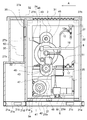
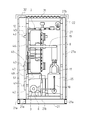
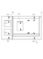
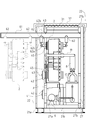
- the block diagram which showed the whole structure of the electric power generating apparatus which concerns on one Embodiment of this invention The side surface partial sectional view which showed the structure of the storage box.
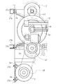
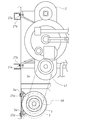
- Side surface partial sectional drawing which showed the structure of the expander and the generator.
- Side surface partial sectional drawing which showed the structure of the expander and the generator.
- the storage box 22 defines the direction of arrow A as the front.
- the power generation device 1 includes an expander 2 driven by steam, a generator 3 driven by being connected to an output shaft 43 of the expander 2, a steam generator 4, a working medium supply pump 6, and a condenser 8. And a control device 50.
- the expander 2 is a scroll-type fluid machine, and high-temperature and high-pressure steam is supplied as a working medium from the steam generator 4 through the working medium passage 12.
- the expander 2 generates power by driving the generator 3 using the supplied steam as a working medium.
- the steam generator 4 is supplied with water from the working medium supply pump 6 through the working medium passage 15.
- the working medium supply pump 6 sucks water generated by condensing steam by the condenser 8 through the working medium passage 17, the working medium tank 25, and the working medium passage 18.
- the condenser 8 is supplied with the steam discharged from the expander 2 through the working medium passage 19.
- the expander 2 drives the generator 3 by converting the energy of the high-temperature and high-pressure steam generated by the steam generator 4 into rotational force.
- the steam discharged from the expander 2 is condensed into water by the condenser 8 and then supplied again to the expander 2 as high-temperature and high-pressure steam by the steam generator 4.
- the control device 50 includes a CPU and storage means.
- the CPU is a central processing unit
- the storage means is a ROM that stores a control program, a map, and the like, and a RAM that stores input data and the like.
- the control device 50 adjusts the amount of high-temperature and high-pressure steam by switching the flow path of the valve 12 a provided in the working medium passage 12.
- the control apparatus 50 adjusts the quantity which attracts
- the expander 2, the generator 3, and the control device 50 that constitute the power generation device 1 are placed on the base 21 and stored in the storage box 22.
- the storage box 22 is a rectangular parallelepiped box, and stores the expander 2, the generator 3, the control device 50, the working medium tank 25 for storing the working medium that has become liquid, and the working medium supply pump 6. To do.
- the lower surface of the storage box 22 is open and provided above the pedestal 21.
- the pedestal 21 is a member for installation on a base such as the ground, and a plurality of steel materials 21a in a cross-sectional view “U” shape or square pipe shape generally called a grooved steel or a square steel pipe are provided in the front-rear direction and the left-right direction. They are arranged one by one and fixed in a frame shape, and a plate-like member 21b is provided on the upper surface. As shown in FIGS. 2, 3, and 4, the pedestal 21 is provided with a ventilation path 21 c for taking outside air into the storage box 22.
- the air passage 21c is composed of a long hole 21d provided in the side surface of the steel material 21a and a long hole 21e provided in a part of the plate-like member 21b.
- the long holes 21d provided in the plate-like member 21b are provided below the space where the control device 50 is arranged in the storage box 22 and below the space where the expander 2 and the generator 3 are arranged in the storage box 22. Yes. As shown by the arrow in FIG. 4, the air that has passed through the long hole 21d passes through the space inside the base 21, and is sent upward through the long hole 21e.
- the storage box 22 has a plurality of frames 27 therein.
- the frame 27 includes a vertical frame 27a erected on the pedestal 21 and a plurality of horizontal frames 27b connecting the upper end and the middle part of the vertical frame 27a.
- four vertical frames 27 a are provided, and the lower ends thereof are erected on the upper surface of the base 21.
- the four vertical frames 27a are arranged so as to be positioned at the vertices of the rectangle in plan view, and the horizontal frames 27b are horizontally provided on the sides of the rectangle connecting the vertices.
- the horizontal frame 27b is provided in parallel with the horizontal direction, and is arranged so as to connect the upper end and the upper end of the vertical frame 27a and the midway part and the midway part.
- the storage box 22 has a partition member 30, and the partition member 30 is erected from the pedestal 21.
- the controller 50 is stored on one side partitioned by the partition member 30, and the expander 2 is mounted on the other side. And the generator 3 are stored.
- a ceiling 31 of the storage box 22 is provided with a mesh plate 31 and a protective roof 32 provided above and around the mesh plate 31 with a predetermined interval so that air can be discharged to the outside.
- the mesh plate 31 is provided so as to cover the ventilation hole opened in the ceiling portion above the expander 2 in the storage box 22.
- the outer periphery of the mesh plate 31 is fixed inside the rectangular ventilation hole that is slightly smaller than the ceiling. The net 31 prevents foreign matter such as dust and insects from entering.
- the protective roof 32 is provided so as to cover the upper portion of the mesh plate 31 and the periphery thereof, and the outer periphery of the protective roof 32 is provided with an edge portion formed by bending downward, covering the ceiling portion of the storage box 22, The edge portion is extended below the gap between the ceiling portion and the protective roof 32 so that rain or the like does not enter from the side. A gap is also provided between the inner surface of the edge and the outer surface of the storage box 22.
- the storage box 22 has a partition member 30 on the side where the control device 50 is stored (hereinafter referred to as the control device 50 side), the side where the expander 2 and the generator 3 are stored (hereinafter referred to as the expander 2 side). And is divided into two spaces. That is, the partition member 30 is erected upward from the front and rear midway part of the base 21, the storage box 22 is partitioned into two front and rear spaces by a plate body, the front side serves as the storage chamber of the control device 50, and the rear side serves as the expander 2. The storage room of the generator 3 is used.
- the control device 50 is disposed on the upper side of the storage box 22 on the control device 50 side.
- a vent hole 33 is provided below the control device 50, and an opening is formed on the surface of the partition member 30 facing the control device 50, and the opening is inflated from the control device 50 side.
- a blower 35 is provided for sending air to the machine 2 side.
- the vent hole 33 is provided above the long hole 21e provided in the pedestal 21, and the air that has passed through the vent passage 21c of the pedestal 21 is sent to the space on the control device 50 side through the vent hole 33.
- the control device 50 is cooled.
- the blower 35 is a device that sends air sent through the vent hole 33 from the control device 50 side to the expander 2 side, and is configured by, for example, a propeller fan or a sirocco fan.
- the generator 3 is arranged on the lower side of the expander 2 side of the storage box 22 and on the control device 50 side.
- the generator 3 has an input shaft 41, and the input shaft 41 protrudes in a horizontal direction and a direction orthogonal to the front-rear direction.
- the generator 3 is fixed to a frame 27 erected on the pedestal 21. More specifically, the generator 3 has a mounting plate 3a projecting toward the frame 27 side.
- the mounting plate 3 a is provided so as to project upward and downward from the front side of the central portion of the generator 3.
- the mounting plate 3a has a screw hole at its end.
- a generator mounting plate 27 c is horizontally provided between the two vertical frames 27 a of the frame 27.
- the generator mounting plate 27c is provided with a long hole 27d as an adjusting portion.
- the long hole 27d is provided so that the vertical direction is the longitudinal direction.
- the frame 27 and the generator 3 are fixed by inserting and fastening screws into the screw holes and the long holes 27d of the mounting plate 3a. Even when a screw is fastened to the lower end of the long hole 27d, the long hole 27d is arranged so that the generator 3 is fixed in a state of being separated above the base 21. Thereby, the generator 3 can be fixed in a state of being separated from the base 21. Further, by moving the position of the screw up and down within the range of the vertical length of the long hole 27d, the vertical position of the generator 3 can be adjusted, and the tension of the belt 48 described later can be adjusted.
- an input pulley 42 is provided on the input shaft 41 of the generator 3.
- the input pulley 42 is provided at the end of the input shaft 41, and a belt 48 is wound around an output pulley 47 described later.
- a working medium tank 25 and a working medium supply pump 6 are arranged at the lower part of the storage box 22 on the expander 2 side and behind the generator 3. Both the working medium tank 25 and the working medium supply pump 6 are fixed to the base 21.
- the working medium tank 25 is a tank for temporarily storing water that has been condensed by the condenser 8 to become liquid.
- the expander 2 is disposed above the generator 3.
- the expander 2 has an output shaft 43 for taking out rotational force.
- Two output shafts 43 are provided vertically.
- Sprockets 45 are respectively provided in the middle of the upper and lower output shafts 43.
- a chain 46 is wound between the sprockets 45 so that the two output shafts 43 are rotated in synchronization. Yes.
- the axial direction of the output shaft 43 is arranged so as to be parallel to the axial direction of the input shaft 41 of the generator 3.
- the expander 2 is fixed to a frame 27 erected on the pedestal 21. More specifically, the expander 2 has a mounting plate 2a projecting toward the frame 27 side. The mounting plate 2a protrudes upward and downward from the front side of the central portion of the expander 2. The mounting plate 2a has a screw hole at its end. Further, a long hole 27e as an adjusting portion is provided on the rear surface of the horizontal frame 27b. The long hole 27e is provided so that the vertical direction is the longitudinal direction. The frame 27 and the expander 2 are fixed by inserting and fastening screws into the screw holes and the long holes 27e of the mounting plate 2a.
- the long hole 27e is arranged so that the expander 2 is fixed in a state of being separated above the generator 3. Thereby, the expander 2 can be fixed in a state of being separated from the base 21 and the generator 3. Further, by moving the position of the screw up and down within the range of the vertical length of the long hole 27e, the vertical position of the expander 2 can be adjusted, and the tension of the belt 48 can be adjusted.
- An output pulley 47 is provided on the lower output shaft 43 of the expander 2, and a belt 48 is wound and connected between the output pulley 47 and the input pulley 42 of the generator 3.
- a condenser 8 is disposed above the working medium tank 25 and behind the expander 2.
- the working medium passage 12 for supplying high-temperature and high-pressure steam from the steam generator 4 provided outside the storage box 22 to the expander 2 is arranged from the upper side of the storage box 22 to the space on the expander 2 side. One end of which is connected to the expander 2.
- the working medium passage 19 for sending steam from the expander 2 to the condenser 8 is provided in the space on the expander 2 side of the storage box 22, one end is connected to the expander 2, and one end is Connected to the condenser 8.
- the working medium passage 17 for supplying water generated by condensing the steam by the condenser 8 is provided in the space on the expander 2 side of the storage box 22, one end being operated by the condenser 8 and the other end being operated. Connected to the medium tank 25.
- the working medium passage 18 for sucking the water stored in the working medium tank 25 is provided in the space on the expander 2 side of the storage box 22, and one end is connected to the working medium tank 25.
- the other end is branched, one end is connected to the working medium supply pump 6, and the other end is connected to the high-pressure liquid supply passage 51.
- the other end of the high pressure liquid supply passage 51 is connected to the central portion of the expander 2.
- the high-pressure liquid is supplied from the central portion of the expander 2 to the inside and is used as a lubricant for the expander 2.
- a pipe (not shown) is provided at the front end of the working medium supply pump 6, and the pipe communicates with an external working medium passage 15.
- the upper part of the storage box 22 becomes relatively warmer than the lower part. Therefore, the air in the upper part of the storage box 22 having a high temperature and a low density further rises and is discharged to the outside from the net 31 of the ceiling part, and a negative pressure is applied to the lower part of the storage box 22 having a low temperature, An air flow utilizing a so-called chimney effect in which a fluid flows from the air passage 21c is created.
- the air blower 35 for sending air to the expander 2 side from the control apparatus 50 side of the storage box 22 is provided, the temperature of the control apparatus 50 side whose temperature is lower than the expander 2 side by the above-mentioned chimney effect. Since negative pressure also acts in the space, an air flow due to the chimney effect is generated in addition to the air blown by the blower 35, so that the blower 35 can be configured with a smaller size than usual.
- the expander 2 is fixed to the horizontal frame 27b at the lowermost end of the long hole 27e, and the belt 48 is wound between the output pulley 47 and the input pulley 42.
- the screw fixing the expander 2 is loosened and the screw is moved to the uppermost position of the long hole 27 e to move the expander 2 upward.
- the tension of the belt 48 is increased.
- the screw is tightened again at the place where the expander 2 is moved and fixed to the horizontal frame 27b. With this configuration, the tension of the belt 48 can be easily adjusted.
- the generator 3 is fixed to the frame 27 at the uppermost end of the long hole 27 d, and a belt 48 is wound between the output pulley 47 and the input pulley 42.
- the screw which fixes the generator 3 is loosened, the screw is moved to the lowermost part of the long hole 27d, and the generator 3 is moved downward. Thereby, the tension of the belt 48 is increased.
- the screw is tightened again at the place where the generator 3 is moved and fixed to the frame 27. With this configuration, the tension of the belt 48 can be easily adjusted.
- the generator 3 is fixed by moving a screw in the middle of the long hole 27d, the generator 3 moves downward due to the weight of the generator 3, so that tension is generated in the belt 48. Thereby, the operation
- the horizontal frame 27b is provided with screw holes for fixing the expander take-out rail member 61.
- the expander take-out rail member 61 is removed, and when the expander 2 is taken out for maintenance or the like, the expander take-out rail member 61 is fixed to the lateral frame 27b with screws.
- the expander take-out rail 61 is made of H-shaped steel, and is attached so that the horizontal direction of the storage box 22 and the direction parallel to the left-right direction is the longitudinal direction when attached to the horizontal frame 27b. Further, the tip of the expander take-out rail member 61 at the time of attachment protrudes from the storage box 22 to the side, so that the expander 2 can be carried out to the storage box 22.
- rail pulleys 62 can be attached to both ends of the output shaft 43 on the upper side of the expander 2.
- the rail pulley 62 has a fixing portion 62a for fixing to the output shaft 43, and rollers 62b provided on both sides so as to sandwich the expander take-out rail material 61.
- the fixing portion 62a has a screw portion 62c, and the position can be adjusted in the vertical direction by rotating the screw portion 62c.
- the rail pulley 62 can slide along the expander take-out rail member 61 by placing the roller 62b on the overhanging portion provided on the lower side of the expander take-out rail member 61 and turning it. .
- the expander take-out rail member 61 is fixed to the horizontal frame 27 b with screws, and the rail pulley 62 is taken out from the end of the expander take-out rail member 61. Sliding along the rail material 61 for use. Then, the fixing portions 62a of the rail pulley 62 are fixed to both ends of the output shaft 43 of the expander 2, respectively.
- the expander 2 is supported in a state of being suspended from the expander take-out rail member 61 via the rail pulley 62.
- the expander 2 moves to the outside of the storage box 22 in a suspended state by sliding the rail pulley 62 to the outside of the storage box 22. With this configuration, the expander 2 can be easily moved to the outside of the storage box 22, so that the expander 2 can be efficiently maintained.
- the power generator 1 includes the expander 2 driven by steam, the generator 3 connected to the output shaft 43 of the expander 2, and the control device 50 mounted on the pedestal 21.
- the storage box 22 has a partition member 30, the partition member 30 is erected from the base 21, and the controller 50 is stored on one side partitioned by the partition member 30, On the other side, the power generator 1 in which the expander 2 and the generator 3 are stored.
- the pedestal 21 is provided with a ventilation path 21 c for taking outside air into the storage box 22.
- the ceiling portion of the slab is provided with a mesh plate 31 and a protective roof 32 provided above and around the mesh plate 31 at a predetermined interval so that air can be discharged to the outside.
- the expander 2 and the generator 3 Is fixed to a frame 27 erected on the base 21 and expanded And 2 and a generator 3 is obtained is separated from the base 21. With this configuration, the air flows from the bottom to the top due to the chimney effect, so that the expander 2, the generator 3, and the control device 50 can be efficiently cooled. Further, since the expander 2 and the generator 3 are separated from the pedestal 21, a passage through which air flows is widened, so that the expander 2, the generator 3, and the control device 50 can be efficiently cooled. Further, by separating the expander 2 and the generator 3 from the base 21, a space for maintaining the expander 2 and the generator 3 is created, and the maintenance can be performed efficiently. Further, foreign matters such as rain can be prevented from entering from above, and durability can be improved and maintenance work can be omitted.
- the partition member 30 is provided with a blower 35 for sending air from the control device 50 side to the expander 2 side.
- a blower 35 for sending air from the control device 50 side to the expander 2 side.
- the generator 3 is disposed below the expander 2, and the expander 2 has an output shaft 43 that protrudes in the horizontal direction.
- the generator 3 has an input shaft 41 that protrudes in the horizontal direction.
- the output shaft 43 and the input shaft 41 are connected by a belt 48.
- the attachment portion of the expander 2 in the frame 27 is provided with a long hole 27e that can be moved by a certain distance in the vertical direction.
- the number and shape of the long holes 21d and 21e of the base 21 are not limited to this. For example, it is possible to provide three or more long holes 21d, and it is also possible to provide two or four or more long holes 21e.
- the adjusting part for adjusting the vertical position of the expander 2 and the generator 3 is not limited to the long holes 27d and 27e.
- blowers 35 are not limited to this.
- two or more blowers can be provided in the partition member 30.
- the present invention is applicable to a power generator having an expander driven by steam, a generator driven by being connected to an output shaft of the expander, a control device, a pedestal, and a storage box.
Landscapes
- Engineering & Computer Science (AREA)
- Mechanical Engineering (AREA)
- General Engineering & Computer Science (AREA)
- Chemical & Material Sciences (AREA)
- Combustion & Propulsion (AREA)
- Connection Of Motors, Electrical Generators, Mechanical Devices, And The Like (AREA)
- Wind Motors (AREA)
- Ventilation (AREA)
Description
また、前記膨張機及び発電機を単一の格納箱内に収納設置したパッケージ型の発電装置が公知となっている(例えば、特許文献1参照)。
また、スクロール型流体機械を格納箱に収納設置したユニット装置であって、前記スクロール型流体機械の下部に空冷用通風ダクトを設け空冷用ファンの吸気側に接続した装置が公知となっている(例えば、特許文献2参照)。
ここで、図2に示すように、格納箱22は、矢印Aの方向を前方として定義する。
まず、発電装置1の構成について図1のブロック図を用いて説明する。
発電装置1は、蒸気により駆動される膨張機2と、膨張機2の出力軸43に連結されて駆動される発電機3と、蒸気発生器4と、作動媒体供給ポンプ6と、凝縮器8と、制御装置50と、を有する。
発電装置1を構成する膨張機2、発電機3、及び制御装置50は、台座21の上に載置されて格納箱22に収納される。
フレーム27は、台座21に立設された縦フレーム27aと、縦フレーム27aの上端及び中途部を接続する複数本の横フレーム27bとから構成される。本実施形態においては、縦フレーム27aは四本設けられており、それぞれの下端が台座21の上面に立設されている。四本の縦フレーム27aは平面視で長方形の頂点に位置するよう配置されており、それぞれの頂点を結ぶ長方形の辺上に横フレーム27bが横設されている。横フレーム27bは、水平方向と平行に横設されており、縦フレーム27aの上端と上端及び中途部と中途部とを接続するように配置されている。
網板31は、格納箱22において膨張機2の上方の天井部に開口された通気用孔を覆うように設けられている。本実施形態では天井よりも一回り小さい四角形状の通気用孔の内側に網板31の外周が固設されている。この網板31によりゴミや虫等の異物が侵入するのを防止する。
防護屋根32は、網板31の上方及びその周囲を覆うように設けられており、防護屋根32の外周は下方に折り曲げ形成された縁部が設けられ、格納箱22の天井部を覆うとともに、前記縁部は天井部と防護屋根32との間の隙間よりも下方に延設されて、側方より雨等が浸入しないように構成されている。なお、縁部の内側面と格納箱22の外側面との間にも隙間が設けられている。
格納箱22は、仕切り部材30によって、制御装置50が格納される側(以下、制御装置50側)と、膨張機2と、発電機3とが格納される側(以下、膨張機2側)と、の二つの空間に仕切られる。即ち、仕切り部材30は台座21の前後中途部から上方に立設され、格納箱22を板体により前後二つの空間に仕切り、前側を制御装置50の格納室とし、後側を膨張機2と発電機3の格納室としている。
これにより、発電機3を台座21から離間させた状態で固定させることができる。また、螺子の位置を長孔27dの上下長さの範囲内で上下させることにより、発電機3の上下位置を調整させることが可能となり、後述するベルト48の張りを調節できる。
作動媒体タンク25は、凝縮器8によって凝縮され液体となった水を一時的に貯溜するためのタンクである。
また格納箱22外に設けられた蒸気発生器4から膨張機2へ高温高圧の蒸気を供給するための作動媒体通路12は、格納箱22の側面上部から膨張機2側の空間にかけて配置されており、その一端が膨張機2に連結されている。
作動媒体供給ポンプ6の前端には、図示せぬパイプが設けられており、前記パイプは外部の作動媒体通路15へと連通している。
まず、膨張機2を長孔27eの一番下端で横フレーム27bに固定し、出力プーリ47と入力プーリ42との間にベルト48を巻回する。次に、図5の二点鎖線で示すように、膨張機2を固定している螺子を緩め長孔27eの一番上方に螺子を移動させて膨張機2を上方へ移動させる。これにより、ベルト48の張力が高まる。次に膨張機2を移動させた場所で再び螺子を締めて横フレーム27bに固定する。このように構成することにより、ベルト48の張力調節が容易となる。
また、長孔27dの中途部に螺子を移動させて発電機3を固定した場合には、発電機3の自重により発電機3が下方へ移動するため、ベルト48に張力が生まれる。これにより、ベルト48の張力を調整する作業を簡易化することができる。
このように構成することにより、膨張機2を容易に格納箱22の外側へ移動させることができるので、効率よく膨張機2のメンテナンスを行うことが可能となる。
このように構成することにより、煙突効果により、下から上へ向けて空気が流れるため、膨張機2、発電機3、及び制御装置50を効率よく冷却することができる。また、膨張機2及び発電機3を台座21から離間させたことにより、空気が流れる通路が広くなるため、膨張機2、発電機3、及び制御装置50を効率よく冷却することができる。また、膨張機2及び発電機3を台座21から離間させたことにより、膨張機2及び発電機3をメンテナンスする際の空間が生まれ、メンテナンスを効率よく行うことができる。また、上方から雨などの異物が入り込むのを防止し、耐久性を向上させて、メンテナンス作業を省くことができる。
このように構成することにより、煙突効果の薄い制御装置50側においても下から上へ向けて空気が流れやすくなるため、膨張機2、発電機3、及び制御装置50を更に効率よく冷却することができる。
このように構成することにより、膨張機2及び発電機3を台座21から離間させたことにより、膨張機2及び発電機3をメンテナンスする際の空間が生まれ、メンテナンスを効率よく行うことができる。また、発電機3の自重によってベルト48に張力が生まれるため、ベルト48の張力を調整する作業を簡易化することができる。
このように構成することにより、膨張機2及び発電機3を台座21から離間させたことにより、膨張機2及び発電機3をメンテナンスする際の空間が生まれ、メンテナンスを効率よく行うことができる。また、膨張機2を上下に移動させて固定することによって、ベルト48の張力を調整する作業をすることができ、作業を簡易化することができる。
2 膨張機
3 発電機
21 台座
21c 通気路
22 格納箱
27 フレーム
27e 長孔(調整部)
30 仕切り部材
31 網板
32 防護屋根
35 送風機
41 入力軸
43 出力軸
48 ベルト
50 制御装置
Claims (4)
- 蒸気により駆動される膨張機と、前記膨張機の出力軸に連結されて駆動される発電機と、制御装置とが台座の上に載置されて格納箱に収納され、
前記格納箱は仕切り部材を有し、該仕切り部材は台座から立設され、該仕切り部材によって仕切られた一側には前記制御装置が格納され、他側には前記膨張機と、発電機とが格納される発電装置であって、
前記台座には、外気を前記格納箱内部へ取り入れるための通気路が設けられ、
前記格納箱の天井部には、網板と、該網板の上方及び周囲に所定の間隔をあけて設けられる防護屋根とが設けられて空気を外部へ排出可能とし、
前記膨張機及び前記発電機は、前記台座上に立設したフレームに固設され、
前記膨張機と前記発電機とを台座から離間させたことを特徴とする発電装置。 - 前記仕切り部材には、前記制御装置側から前記膨張機側へ空気を送り込むための送風機が設けられたことを特徴とする請求項1に記載の発電装置。
- 前記発電機は、膨張機の下方に配置され、
前記膨張機は、水平方向に突出した出力軸を有し、
前記発電機は、水平方向に突出した入力軸を有し、
前記出力軸と前記入力軸とがベルトで連結されたことを特徴とする請求項1または2に記載の発電装置。 - 前記フレームにおける膨張機の取付部には、上下方向に一定距離だけ移動させることができる調整部が設けられたことを特徴とする請求項1に記載の発電装置。
Priority Applications (5)
| Application Number | Priority Date | Filing Date | Title |
|---|---|---|---|
| KR20147027334A KR20140136966A (ko) | 2012-03-02 | 2013-02-28 | 발전 장치 |
| US14/382,446 US20150102602A1 (en) | 2012-03-02 | 2013-02-28 | Power generating device |
| EP13755237.8A EP2829694A4 (en) | 2012-03-02 | 2013-02-28 | DEVICE FOR GENERATING ELECTRICITY |
| CN201380012214.4A CN104145090B (zh) | 2012-03-02 | 2013-02-28 | 发电装置 |
| IN7832DEN2014 IN2014DN07832A (ja) | 2012-03-02 | 2014-09-19 |
Applications Claiming Priority (2)
| Application Number | Priority Date | Filing Date | Title |
|---|---|---|---|
| JP2012-047344 | 2012-03-02 | ||
| JP2012047344A JP5887167B2 (ja) | 2012-03-02 | 2012-03-02 | 発電装置 |
Publications (1)
| Publication Number | Publication Date |
|---|---|
| WO2013129550A1 true WO2013129550A1 (ja) | 2013-09-06 |
Family
ID=49082742
Family Applications (1)
| Application Number | Title | Priority Date | Filing Date |
|---|---|---|---|
| PCT/JP2013/055333 Ceased WO2013129550A1 (ja) | 2012-03-02 | 2013-02-28 | 発電装置 |
Country Status (7)
| Country | Link |
|---|---|
| US (1) | US20150102602A1 (ja) |
| EP (1) | EP2829694A4 (ja) |
| JP (1) | JP5887167B2 (ja) |
| KR (1) | KR20140136966A (ja) |
| CN (1) | CN104145090B (ja) |
| IN (1) | IN2014DN07832A (ja) |
| WO (1) | WO2013129550A1 (ja) |
Families Citing this family (1)
| Publication number | Priority date | Publication date | Assignee | Title |
|---|---|---|---|---|
| JP6275765B2 (ja) * | 2016-03-28 | 2018-02-07 | 三菱重工業株式会社 | 舶用蒸気タービンモジュール構造 |
Citations (13)
| Publication number | Priority date | Publication date | Assignee | Title |
|---|---|---|---|---|
| JPH0622417A (ja) * | 1992-07-07 | 1994-01-28 | Toshiba Corp | 閉鎖配電盤 |
| JPH08284662A (ja) * | 1995-04-17 | 1996-10-29 | Denyo Kk | 防音形水冷式エンジン溶接機の冷却構造 |
| JP2000110767A (ja) | 1998-10-06 | 2000-04-18 | Hitachi Ltd | ダブルスクロール流体機械及びそのパッケージ型ユニット装置 |
| JP2002242759A (ja) * | 2001-02-14 | 2002-08-28 | Yanmar Diesel Engine Co Ltd | コージェネレーション装置の構造 |
| JP2005155542A (ja) * | 2003-11-27 | 2005-06-16 | Sanyo Electric Co Ltd | コ・ジェネレーションシステム |
| WO2007020707A1 (ja) * | 2005-08-19 | 2007-02-22 | Saga University | 温度差発電装置 |
| JP2007074894A (ja) | 2005-08-11 | 2007-03-22 | Kobe Steel Ltd | 発電装置 |
| JP2009121244A (ja) * | 2007-11-12 | 2009-06-04 | Honda Motor Co Ltd | 防音密閉型発電機 |
| JP2009191800A (ja) * | 2008-02-15 | 2009-08-27 | Yanmar Co Ltd | エンジン発電装置 |
| JP2009228604A (ja) * | 2008-03-24 | 2009-10-08 | Kobe Steel Ltd | 発電システム及び発電システムの制御方法 |
| JP2009270486A (ja) * | 2008-05-07 | 2009-11-19 | Yanmar Co Ltd | パッケージ収納型エンジン発電機におけるコントロールボックスおよび電力変換器の配置構造 |
| JP2011511209A (ja) * | 2008-02-07 | 2011-04-07 | シティ ユニヴァーシティ | 中温熱源からの発電 |
| JP2012007600A (ja) * | 2010-06-25 | 2012-01-12 | Elson Kk | 分散型熱電併給設備及び分散型バイオマス熱電併給設備 |
Family Cites Families (18)
| Publication number | Priority date | Publication date | Assignee | Title |
|---|---|---|---|---|
| US1575665A (en) * | 1923-11-22 | 1926-03-09 | Superheater Co Ltd | Power plant |
| US2707239A (en) * | 1948-12-20 | 1955-04-26 | Frederick W Richl | Apparatus for utilizing waste heat |
| US3418485A (en) * | 1965-09-13 | 1968-12-24 | Caterpillar Tractor Co | Enclosure for gas turbine engine electric generator set |
| US3791682A (en) * | 1972-08-23 | 1974-02-12 | Stewart & Stevenson Serv Inc | Turbine driven electrical generator |
| US4098200A (en) * | 1976-12-09 | 1978-07-04 | Dauvergne Hector A | Low pollution solid waste burner |
| US4207840A (en) * | 1978-09-14 | 1980-06-17 | Dauvergne Hector A | Oil bath boiler |
| US4359951A (en) * | 1981-01-26 | 1982-11-23 | Dauvergne Hector A | Low profile portable power plant |
| US4643133A (en) * | 1985-03-14 | 1987-02-17 | Dauvergne Hector A | Cluster boiler |
| JPH0626399A (ja) * | 1992-07-08 | 1994-02-01 | Nippondenso Co Ltd | 熱電併給装置 |
| JP3018226B2 (ja) * | 1996-01-25 | 2000-03-13 | デンヨー株式会社 | 大型エンジン作業機の開閉扉 |
| US5632147A (en) * | 1996-04-10 | 1997-05-27 | Greer; William | Solar powered steam turbine generator |
| JPH1193690A (ja) * | 1997-09-24 | 1999-04-06 | Sts Kk | ガスタービン駆動動力装置 |
| US6053418A (en) * | 1998-01-14 | 2000-04-25 | Yankee Scientific, Inc. | Small-scale cogeneration system for producing heat and electrical power |
| US6128903A (en) * | 1998-09-11 | 2000-10-10 | Riege; Carl Ralph | Solar portable steam engine |
| WO2002065620A1 (en) * | 2001-02-13 | 2002-08-22 | Yanmar Co.,Ltd. | Electric power system with engine-driven generator |
| JP3934898B2 (ja) * | 2001-09-25 | 2007-06-20 | 本田技研工業株式会社 | エンジン発電機 |
| JP4918404B2 (ja) * | 2007-05-14 | 2012-04-18 | 三菱重工業株式会社 | 低圧蒸気回収タービンおよびその設置方法 |
| DE102009010420B4 (de) * | 2009-02-26 | 2016-03-24 | Schwieger Piper Wichmann GbR (vertretungsberechtigter Gesellschafter: Dr.Hartwig Schwieger, 29227 Celle) | Heizungsvorrichtung zum Beheizen eines Gebäudes mittels einer Verbrennungskraftmaschine |
-
2012
- 2012-03-02 JP JP2012047344A patent/JP5887167B2/ja active Active
-
2013
- 2013-02-28 KR KR20147027334A patent/KR20140136966A/ko not_active Ceased
- 2013-02-28 WO PCT/JP2013/055333 patent/WO2013129550A1/ja not_active Ceased
- 2013-02-28 EP EP13755237.8A patent/EP2829694A4/en not_active Withdrawn
- 2013-02-28 US US14/382,446 patent/US20150102602A1/en not_active Abandoned
- 2013-02-28 CN CN201380012214.4A patent/CN104145090B/zh not_active Expired - Fee Related
-
2014
- 2014-09-19 IN IN7832DEN2014 patent/IN2014DN07832A/en unknown
Patent Citations (13)
| Publication number | Priority date | Publication date | Assignee | Title |
|---|---|---|---|---|
| JPH0622417A (ja) * | 1992-07-07 | 1994-01-28 | Toshiba Corp | 閉鎖配電盤 |
| JPH08284662A (ja) * | 1995-04-17 | 1996-10-29 | Denyo Kk | 防音形水冷式エンジン溶接機の冷却構造 |
| JP2000110767A (ja) | 1998-10-06 | 2000-04-18 | Hitachi Ltd | ダブルスクロール流体機械及びそのパッケージ型ユニット装置 |
| JP2002242759A (ja) * | 2001-02-14 | 2002-08-28 | Yanmar Diesel Engine Co Ltd | コージェネレーション装置の構造 |
| JP2005155542A (ja) * | 2003-11-27 | 2005-06-16 | Sanyo Electric Co Ltd | コ・ジェネレーションシステム |
| JP2007074894A (ja) | 2005-08-11 | 2007-03-22 | Kobe Steel Ltd | 発電装置 |
| WO2007020707A1 (ja) * | 2005-08-19 | 2007-02-22 | Saga University | 温度差発電装置 |
| JP2009121244A (ja) * | 2007-11-12 | 2009-06-04 | Honda Motor Co Ltd | 防音密閉型発電機 |
| JP2011511209A (ja) * | 2008-02-07 | 2011-04-07 | シティ ユニヴァーシティ | 中温熱源からの発電 |
| JP2009191800A (ja) * | 2008-02-15 | 2009-08-27 | Yanmar Co Ltd | エンジン発電装置 |
| JP2009228604A (ja) * | 2008-03-24 | 2009-10-08 | Kobe Steel Ltd | 発電システム及び発電システムの制御方法 |
| JP2009270486A (ja) * | 2008-05-07 | 2009-11-19 | Yanmar Co Ltd | パッケージ収納型エンジン発電機におけるコントロールボックスおよび電力変換器の配置構造 |
| JP2012007600A (ja) * | 2010-06-25 | 2012-01-12 | Elson Kk | 分散型熱電併給設備及び分散型バイオマス熱電併給設備 |
Non-Patent Citations (1)
| Title |
|---|
| See also references of EP2829694A4 * |
Also Published As
| Publication number | Publication date |
|---|---|
| JP5887167B2 (ja) | 2016-03-16 |
| EP2829694A1 (en) | 2015-01-28 |
| JP2013181509A (ja) | 2013-09-12 |
| KR20140136966A (ko) | 2014-12-01 |
| IN2014DN07832A (ja) | 2015-04-24 |
| EP2829694A4 (en) | 2015-09-09 |
| CN104145090A (zh) | 2014-11-12 |
| US20150102602A1 (en) | 2015-04-16 |
| CN104145090B (zh) | 2016-04-06 |
Similar Documents
| Publication | Publication Date | Title |
|---|---|---|
| US10227981B2 (en) | Package type fluid machine | |
| JP6033471B2 (ja) | 発電タービンパッケージ用通気型換気システム | |
| US10137909B2 (en) | Air compressor unit for vehicle | |
| RU2560344C2 (ru) | Наружный блок охлаждающего устройства | |
| RU2581554C2 (ru) | Наружный блок охлаждающего устройства | |
| JP2009068743A (ja) | 空気調和機 | |
| JP2014134183A (ja) | 機関室の換気装置 | |
| JP5887167B2 (ja) | 発電装置 | |
| KR102592232B1 (ko) | 유체기계용 공랭식 냉각장치 | |
| JP4900558B2 (ja) | 室外機 | |
| JP5433611B2 (ja) | パッケージ型圧縮機 | |
| JP5982723B2 (ja) | 防音型エンジン駆動作業機 | |
| CN104265604B (zh) | 用于电力系统的空气压缩机设备 | |
| JP2022053349A (ja) | カバー | |
| JP4580878B2 (ja) | 空気圧装置ステーション及び空気圧装置の収納ボックス | |
| JP5119558B2 (ja) | 空気圧装置ステーション及び空気圧装置の収納ボックス | |
| CN2725760Y (zh) | 空调装置的室外单元 | |
| CN106969427A (zh) | 空气调节机的室外单元及空气调节机 | |
| CN113873810A (zh) | 一种物联网安防用高效监控主机 | |
| JP2022053350A (ja) | カバー、給水装置、および給水装置のメンテナンス方法 | |
| JP6162424B2 (ja) | ガスタービン発電プラント及び複合発電設備 | |
| KR101302862B1 (ko) | 증기복수기용 방음구조 | |
| JP2008148426A (ja) | 発電装置 | |
| CN119212281A (zh) | 用于火电厂的仪表柜 | |
| CN204258546U (zh) | 空空冷无刷励磁同步电动机 |
Legal Events
| Date | Code | Title | Description |
|---|---|---|---|
| WWE | Wipo information: entry into national phase |
Ref document number: 201380012214.4 Country of ref document: CN |
|
| 121 | Ep: the epo has been informed by wipo that ep was designated in this application |
Ref document number: 13755237 Country of ref document: EP Kind code of ref document: A1 |
|
| DPE1 | Request for preliminary examination filed after expiration of 19th month from priority date (pct application filed from 20040101) | ||
| NENP | Non-entry into the national phase |
Ref country code: DE |
|
| WWE | Wipo information: entry into national phase |
Ref document number: 14382446 Country of ref document: US |
|
| REEP | Request for entry into the european phase |
Ref document number: 2013755237 Country of ref document: EP |
|
| WWE | Wipo information: entry into national phase |
Ref document number: 2013755237 Country of ref document: EP |
|
| ENP | Entry into the national phase |
Ref document number: 20147027334 Country of ref document: KR Kind code of ref document: A |