WO2013132544A1 - Echangeur de chaleur et système de pompe à chaleur avec échangeur de chaleur - Google Patents
Echangeur de chaleur et système de pompe à chaleur avec échangeur de chaleur Download PDFInfo
- Publication number
- WO2013132544A1 WO2013132544A1 PCT/JP2012/002823 JP2012002823W WO2013132544A1 WO 2013132544 A1 WO2013132544 A1 WO 2013132544A1 JP 2012002823 W JP2012002823 W JP 2012002823W WO 2013132544 A1 WO2013132544 A1 WO 2013132544A1
- Authority
- WO
- WIPO (PCT)
- Prior art keywords
- heat exchanger
- heat transfer
- heat
- transfer tube
- lid
- Prior art date
- Legal status (The legal status is an assumption and is not a legal conclusion. Google has not performed a legal analysis and makes no representation as to the accuracy of the status listed.)
- Ceased
Links
Images


Classifications
-
- F—MECHANICAL ENGINEERING; LIGHTING; HEATING; WEAPONS; BLASTING
- F28—HEAT EXCHANGE IN GENERAL
- F28D—HEAT-EXCHANGE APPARATUS, NOT PROVIDED FOR IN ANOTHER SUBCLASS, IN WHICH THE HEAT-EXCHANGE MEDIA DO NOT COME INTO DIRECT CONTACT
- F28D7/00—Heat-exchange apparatus having stationary tubular conduit assemblies for both heat-exchange media, the media being in contact with different sides of a conduit wall
- F28D7/0008—Heat-exchange apparatus having stationary tubular conduit assemblies for both heat-exchange media, the media being in contact with different sides of a conduit wall the conduits for one medium being in heat conductive contact with the conduits for the other medium
- F28D7/0025—Heat-exchange apparatus having stationary tubular conduit assemblies for both heat-exchange media, the media being in contact with different sides of a conduit wall the conduits for one medium being in heat conductive contact with the conduits for the other medium the conduits for one medium or the conduits for both media being flat tubes or arrays of tubes
-
- F—MECHANICAL ENGINEERING; LIGHTING; HEATING; WEAPONS; BLASTING
- F28—HEAT EXCHANGE IN GENERAL
- F28F—DETAILS OF HEAT-EXCHANGE AND HEAT-TRANSFER APPARATUS, OF GENERAL APPLICATION
- F28F1/00—Tubular elements; Assemblies of tubular elements
- F28F1/02—Tubular elements of cross-section which is non-circular
- F28F1/022—Tubular elements of cross-section which is non-circular with multiple channels
-
- F—MECHANICAL ENGINEERING; LIGHTING; HEATING; WEAPONS; BLASTING
- F28—HEAT EXCHANGE IN GENERAL
- F28F—DETAILS OF HEAT-EXCHANGE AND HEAT-TRANSFER APPARATUS, OF GENERAL APPLICATION
- F28F9/00—Casings; Header boxes; Auxiliary supports for elements; Auxiliary members within casings
- F28F9/02—Header boxes; End plates
-
- F—MECHANICAL ENGINEERING; LIGHTING; HEATING; WEAPONS; BLASTING
- F28—HEAT EXCHANGE IN GENERAL
- F28F—DETAILS OF HEAT-EXCHANGE AND HEAT-TRANSFER APPARATUS, OF GENERAL APPLICATION
- F28F2275/00—Fastening; Joining
- F28F2275/04—Fastening; Joining by brazing
Definitions
- the present invention relates to a laminated heat exchanger configured by laminating heat transfer tubes and a heat pump system including the heat exchanger.
- Such a heat exchanger includes a first flat tube that conducts a refrigerant that is a low-temperature fluid and a second flat tube that conducts a refrigerant that is a high-temperature fluid such that the refrigerant flows in the first direction.
- the flat tube and the second flat tube are laminated.
- the at least one flat tube is composed of a plurality of flat tubes arranged in the stacking direction, and both ends of the plurality of flat tubes are connected to each other in the flow direction and the stacking direction.
- an inlet header and an outlet header constitute a parallel flow path, and either the inlet header or the outlet header is constituted by a tubular header,
- a plurality of flat tubes constituting parallel flow paths are bundled and connected so that the tube axis direction of the tubular header and the flow direction of fluid in the flat tubes are the same (for example, Patent Document See 1 .
- the heat exchanger as described in Patent Document 1 adopts a structure in which heat transfer tubes (flat tubes) are laminated, it has high performance and high space efficiency.
- at least one of the header tubes into which the refrigerant flows is connected to a heat transfer tube bent in a direction perpendicular to the stacking direction of the heat transfer tubes, the heat transfer tube at that time is bent in the width direction.
- the present invention has been made to solve the above-described problems.
- a heat exchanger that eliminates bending in the width direction of the heat transfer tube and reduces dead space due to the header tube, and the heat exchanger are provided. It aims at providing the heat pump system provided.
- the heat exchanger includes a plurality of first heat transfer tubes having a flow path through which a first fluid flows, and a flow path through which the second fluid flows, alternately stacked with the first heat transfer tubes.
- a plurality of second heat transfer tubes, a first header that distributes the first fluid to the first heat transfer tubes, a second header that distributes the second fluid to the second heat transfer tubes, and the first header A lid projecting portion communicating with the first heat transfer tube, a first lid provided at a flow channel end portion of the first heat transfer tube, and a lid projecting portion communicating with the second header, and a flow channel of the second heat transfer tube.
- a second lid provided at the end, and the lid protrusion of the first lid and the lid protrusion of the second lid are arranged in the stacking direction of the first heat transfer tube and the second heat transfer tube. It is arranged so that it does not overlap, and each of the first header and the second header has a width of the first heat transfer tube and the second heat transfer tube. It is intended to be disposed ⁇ .
- the heat pump system includes a first refrigerant circuit and a second refrigerant circuit that are cascade-connected via the heat exchanger.
- the first header and the second header do not protrude into the width of the first heat transfer tube and the second heat transfer tube, and the dead space in the width direction of the heat transfer tube can be reduced. it can. As a result, the entire heat exchanger can be made compact.
- the unit on which the heat exchanger is mounted can be made compact.
- FIG. 1 It is a schematic perspective view which shows an example of the external appearance structure of the heat exchanger which concerns on Embodiment 1 of this invention. It is explanatory drawing for demonstrating the heat exchanger which concerns on Embodiment 1 of this invention. It is explanatory drawing for demonstrating the cover inserted in the flow-path edge part of the heat exchanger which concerns on Embodiment 1 of this invention. It is principal part sectional drawing which shows the structure of the heat exchanger which concerns on Embodiment 1 of this invention. It is explanatory drawing for demonstrating the heat exchanger which concerns on Embodiment 2 of this invention. It is explanatory drawing for demonstrating the heat exchanger which concerns on Embodiment 3 of this invention.
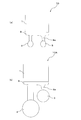
- FIG. 1 is a schematic perspective view showing an example of an external configuration of a heat exchanger 10 according to Embodiment 1 of the present invention.
- FIG. 2 is an explanatory diagram for explaining the heat exchanger 10 ((a) is a top view, (b) is an AA cross-sectional view, and (c) is a side view).
- FIG. 3 is an explanatory view for explaining a lid inserted into the end of the flow path of the heat exchanger 10 ((a) is a front view and (b) is a top view).
- FIG. 4 is a cross-sectional view of a main part showing the configuration of the heat exchanger 10.
- the heat exchanger 10 includes a plurality of first heat transfer tubes 1 and second heat transfer tubes 2 having the same length and having a flow path through which a fluid such as a refrigerant flows. It has a structure.
- the first heat transfer tube 1 and the second heat transfer tube 2 have a flat cross-sectional shape that is a straight line at the long side portion and a semicircular shape at the short side portion, for example.
- the 1st heat exchanger tube 1 and the 2nd heat exchanger tube 2 are laminated
- the first heat transfer tube 1 and the second heat transfer tube 2 are joined to each other using a brazing material 21 on the joining surface 7. By using the brazing material 21, it is possible to improve the brazing performance of the lid 8 to be mounted thereafter.
- a plurality of communication holes 1a are provided in the first heat transfer tube 1 side by side in the width direction.
- a plurality of communication holes 2a are provided side by side in the width direction.
- a fluid flows inside the communication hole 1a and the communication hole 2a. That is, the communication hole 1a and the communication hole 2a serve as a fluid flow path.
- the fluid flowing through the communication hole 1a of the first heat transfer tube 1 is referred to as a first refrigerant
- the fluid flowing through the communication hole 2a of the second heat transfer tube 2 is referred to as a second refrigerant.
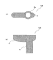
- a lid 8 having a lid protrusion 8a as shown in FIG. 3 is provided at the flow path end 5 of the first heat transfer tube 1 and the flow path end 6 of the second heat transfer tube 2.
- the lid 8 is provided at the flow path end 5 of the first heat transfer tube 1 and the flow path end 6 of the second heat transfer tube 2 so that the lid protrusion 8a does not overlap in the stacking direction of the heat transfer tubes.
- the lid 8 provided at the flow path end 5 of the first heat transfer tube 1 corresponds to the first lid of the present invention, and the lid 8 provided at the flow path end 6 of the second heat transfer tube 2 is provided. This corresponds to the second lid of the present invention.
- the lid protrusion 8 a is provided so as to be biased to one side in the width direction of the lid 8.
- the lid protrusion 8a of the lid 8 provided at the flow path end 5 of the first heat transfer tube 1 and the lid protrusion 8a of the lid 8 provided at the flow path end 6 of the second heat transfer tube 2 are transferred. It arrange
- the first header 3 is provided so that the lid protrusion 8 a provided at the flow path end 5 of the first heat transfer tube 1 communicates in the stacking direction of the first heat transfer tube 1.
- the 2nd header 4 is provided so that the cover protrusion part 8a provided in the flow-path edge part 6 of the 2nd heat exchanger tube 2 may be connected in the lamination direction of the 2nd heat exchanger tube 2.
- FIG. That is, the first header 3 and the second header 4 are arranged so as to be arranged in parallel without protruding from the width of the first heat transfer tube 1 and the second heat transfer tube 2 when the heat exchanger 10 is viewed from the header side. Has been.
- the first and second refrigerants communicate with each other by the first header 3 and the second header 4.
- the heat exchanger 10 should just comprise the heat exchanger tube part by laminating
- the heat transfer tube portion may be configured by laminating the heat tubes 2, or the heat transfer tube portion may be configured by integrally forming the first heat transfer tube 1 and the second heat transfer tube 2 by integral extrusion molding or integral drawing. .
- integrally molding the first heat transfer tube 1 and the second heat transfer tube 2 the number of parts can be reduced, the brazing of the heat transfer tube portion becomes unnecessary, and the performance as a heat exchanger can be improved. it can.
- the second heat transfer tube 2 is made of a material having good thermal conductivity, such as an aluminum alloy, copper, stainless steel or the like.
- the second heat transfer tube 2 is formed by bending a flat plate by roll forming or the like and then electro-sewing (welding) seams at both ends of the flat plate, roll forming or press forming a cylinder, or extrusion forming. Alternatively, it can be produced by pultrusion.
- the first heat transfer tube 1 is made of a material having good heat conductivity, for example, an aluminum alloy, copper, stainless steel or the like, similar to the second heat transfer tube 2, but is formed by extrusion or pultrusion. Is manufactured by.
- the first header joint 50 which is a connecting portion between the first heat transfer tube 1 and the first header 3, is brazed using a brazing material 21 such as an aluminum-silicon system.
- the second header joint portion 51 which is a connection portion between the second heat transfer tube 2 and the second header 4, is brazed using a brazing material 21 such as an aluminum-silicon system.
- the port 3 ⁇ / b> A of the first header 3 and the port 4 ⁇ / b> A of the second header 4 are connected to a refrigerant circuit of a cooling system such as a heat pump device, which will be described later, on which the heat exchanger 10 is mounted.
- the lid 8 is made of a material having good thermal conductivity, such as an aluminum alloy, copper, stainless steel or the like.
- the lid protrusion 8a is made of a material having good thermal conductivity, such as aluminum alloy, copper, stainless steel, etc., and is constructed as a separate part from the lid 8, or as an integrally molded product such as casting.
- the lid 8 is configured as a processed product such as cutting.
- the shape of the lid protrusion 8a provided at the end of the lid 8 is shown as a circular shape in FIGS. 1 and 3, but is not limited to this, for example, a rectangular shape, an elliptical shape, other shapes, etc. But you can.
- the heat exchanger 10 has a flat surface (joint surface 7) of the first heat transfer tube 1 and a flat surface (joint surface 7) of the second heat transfer tube 2 made of, for example, aluminum-silicon. It is configured by brazing and joining using a brazing material 21. With such a configuration, the heat exchanger 10 can reduce the dead space in the width direction of the heat transfer tubes, and the entire heat exchanger can be made compact. In other words, in the conventional heat exchanger, the header tube has been arranged so as to widen the width direction of the heat transfer tube, thereby reducing the space efficiency, but in the heat exchanger 10, without increasing the width direction of the heat transfer tube, The dead space can be reduced accordingly.
- first heat transfer tubes 1 and second heat transfer tubes having the same length and having a refrigerant flow path through which the refrigerant flows are prepared. And the 1st heat exchanger tube 1 and the 2nd heat exchanger tube 2 are laminated alternately.
- a lid 8 having a lid protrusion 8 a is attached to the flow path end 5 of the first heat transfer tube 1 and the flow path end 6 of the second heat transfer tube 2.
- the heat transfer tube portion of the heat exchanger 10 is formed by brazing the joining surfaces of the first heat transfer tube 1 and the second heat transfer tube 2 and the lid 8 and the periphery of the lid 8.
- a lid mounting portion 9 a is provided at the flow path end 5 of the first heat transfer tube 1 and the flow path end 6 of the second heat transfer tube 2.
- the heat transfer tube mounting portion 9b is provided at the end portion of 8 as well. That is, it is preferable that the lid mounting portion 9a is male and the heat transfer tube mounting portion 9b is female so that both can be mounted and brazing can be performed smoothly.
- the lid protrusion 8a using the lid protrusion 8a, the first heat transfer tube 1 and the first header 3 are communicated, the second heat transfer tube 2 and the second header 4 are communicated, and the lid projection 8a, the first header 3, and the lid The protrusion 8a and the second header 4 are connected and brazed.
- the heat exchanger 10 is completed by the manufacturing method as described above.
- the heat exchanger 10 is mounted in a refrigerant circuit of a cooling system such as a heat pump device that uses hot or cold heat.
- a cooling system such as a heat pump device that uses hot or cold heat.
- coolant from a refrigerant circuit is supplied to the 1st heat exchanger tube 1, and it returns to a refrigerant circuit through the communicating hole 1a.
- coolant is supplied to the 2nd heat exchanger tube 2, and the 2nd refrigerant
- the first refrigerant and the second refrigerant exchange heat by flowing through the first heat transfer tube 1 and the second heat transfer tube 2 in a counterflow or parallel flow.
- coolant flow path cross-sectional area of the 2nd heat exchanger tube 2 may be the same, it does not necessarily need to be the same.
- the thermophysical value such as specific heat and density, the flow rate, the pressure condition, or the fluid property between the first refrigerant and the second refrigerant
- the refrigerant channel cross-sectional area is set to the first heat transfer tube. What is necessary is just to make it differ with 1 and the 2nd heat exchanger tube 2.
- the refrigerant flow passage area is preferably larger than the first heat transfer tube 1.
- the first heat transfer tube 1 and the second heat transfer tube 2 have been described using the same type of metal, but may be manufactured using different metals.
- the lid and header tube connected to the first heat transfer tube 1 are copper and the second heat transfer tube.
- Each of the heat transfer tubes, the lid, and the header tube may be made of the same type of metal so that the lid and header tube connected to 2 are made of aluminum.
- the lid and header tube connected to each heat transfer tube are made of a metal (for example, stainless steel) other than copper and aluminum.
- FIG. FIG. 5 is an explanatory diagram for explaining a heat exchanger 10A according to Embodiment 2 of the present invention (a top view showing an enlarged main part of the heat exchanger 10 according to Embodiment 1).
- the figure and (b) are the top views which expand and show the principal part of 10 A of heat exchangers which concern on Embodiment 2.
- FIG. The heat exchanger 10A will be described based on FIG.
- the basic configuration of the heat exchanger 10A according to the second embodiment is the same as that of the heat exchanger 10 described in the first embodiment. In the second embodiment, differences from the first embodiment will be mainly described, and the same parts as those in the first embodiment will be denoted by the same reference numerals and description thereof will be omitted.
- the heat exchanger 10A adopts a configuration in which the larger lid protrusion 8a is lengthened when at least one of the first header 3 and the second header 4 becomes larger.
- FIG. 5 shows an example in which the second header 4 is larger.
- the large header means that the area is large when the header is viewed in plan.
- To lengthen the lid protrusion 8a means to make it longer than the length of the other lid protrusion 8a in the refrigerant flow direction. How much longer it may be determined by the size of the smaller header (first header 3 in FIG. 5).
- Other configurations and functions are the same as those of the heat exchanger 10 shown in the first embodiment.
- the first header 3 and the second header 4 can be arranged without interference. That is, when the first header 3 and the second header 4 having a size as shown in FIG. 5A are arranged in parallel, the first heat transfer tube 1 and the second heat transfer tube 2 are arranged in the direction of widening the width direction. As shown in FIG. 5 (b), the lid protrusion 8a connected to the larger header can be lengthened so that interference between the headers can be avoided and the dead space in the width direction of the heat transfer tube is reduced. Therefore, the entire heat exchanger can be made compact.
- FIG. 6 is an explanatory diagram for explaining a heat exchanger 10B according to Embodiment 3 of the present invention ((a) is a front view and (b) is a top view).
- FIG. 7 is a schematic side view showing a state in which the main part of the heat exchanger 10B is viewed from the side.
- the heat exchanger 10B will be described based on FIGS.
- the basic configuration of the heat exchanger 10B according to Embodiment 3 is the same as that of the heat exchanger 10 described in Embodiment 1.
- differences from the first and second embodiments will be mainly described, and the same parts as those in the first and second embodiments will be denoted by the same reference numerals and the description thereof will be omitted. It shall be.
- the heat exchanger 10B is configured so that the thickness of the lid protrusion 8a (thickness in the stacking direction of the heat transfer tubes) is changed from the thickness of the lid 8 (thickness in the stacking direction of the heat transfer tubes). It is different from the heat exchangers according to the first and second embodiments in that a configuration in which the through hole 15 is provided so as to penetrate the surface where the lid protrusions 8a are in contact with each other when the 8a is increased to contact with the stacking direction. ing.
- the flow path cross-sectional area of the lid protrusion 8a is made larger than that of the lid protrusion 8a of the heat exchanger according to Embodiment 1 and Embodiment 2.
- Other configurations and functions are the same as those of the heat exchanger according to the first and second embodiments.
- the use of the through-hole 15 becomes an alternative to the header, and the number of parts can be reduced.
- the end sealing material 9c may be used for sealing.
- it can replace with a header by connecting the connection port 16 to the through-hole 15 formed in the lid
- the first header 3 and the second header 4 can be omitted, and the dead space can be reduced accordingly. That is, if the cover protrusion 8a having the structure as shown in FIG. 7 is provided, the first header 3 and the second header 4 are not provided, and there is a problem of dead space caused by the presence of the header. Disappear. Therefore, according to the heat exchanger 10B, the entire heat exchanger can be made compact by the amount that the header is not provided.
- FIG. FIG. 8 is a schematic sectional drawing which shows the principal part cross section of the heat exchanger tube part of the heat exchanger which concerns on Embodiment 4 of this invention. Based on FIG. 8, the heat exchanger tube part (the 1st heat exchanger tube 1 and the 2nd heat exchanger tube 2) of the heat exchanger which concerns on Embodiment 4 is demonstrated.
- the basic configuration of the heat exchanger according to the fourth embodiment is the same as that of the heat exchanger 10 described in the first embodiment. In the fourth embodiment, differences from the first to third embodiments will be mainly described. The same parts as those in the first to third embodiments are denoted by the same reference numerals, and the description thereof is omitted. It shall be.
- Embodiment 4 demonstrates several patterns of the cross-sectional shape of the 1st heat exchanger tube 1 and the 2nd heat exchanger tube 2 which comprise a heat exchanger.
- FIG. 8A shows a heat transfer tube portion whose cross-sectional shape is rectangular
- FIG. 8B shows a heat transfer tube portion whose cross-sectional shape is elliptical
- FIG. 8C shows an elliptical cross-sectional shape.
- the heat transfer tube portion having a shape and a groove formed on the inner peripheral surface, and the heat transfer tube portion in which the corrugated plate is inserted in FIG.
- FIG. 8 (e) shows a heat transfer tube portion in which the cross-sectional shape is an elliptical shape and a large number of holes are formed inside.
- the heat exchangers according to Embodiments 1 to 3 include a heat transfer tube portion having a rectangular cross-sectional shape and formed with a plurality of communication holes (communication holes 1a and 2a).
- the shape of the heat transfer tube portion may be a shape as shown in FIG. 8 or a shape obtained by appropriately combining them.
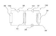
- FIG. FIG. 9 is a circuit diagram schematically showing an example of the basic configuration of the heat pump system 100 according to Embodiment 5 of the present invention.
- FIG. 10 is a circuit diagram schematically showing another example of the basic configuration of the heat pump system 100 according to Embodiment 5 of the present invention.
- FIG. 11 is a circuit diagram schematically showing still another example of the basic configuration of the heat pump system 100 according to Embodiment 5 of the present invention.
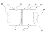
- FIG. 12 is a circuit diagram schematically showing still another example of the basic configuration of the heat pump system 100 according to Embodiment 5 of the present invention.
- the heat pump system 100 will be described with reference to FIGS.
- the heat pump system 100 shown in FIGS. 9 to 12 includes the heat exchanger according to any of the first to third embodiments, and two circuits are cascade-connected via the heat exchanger.
- the exchanger includes the heat transfer tube section shown in any of the fourth embodiment. Therefore, in heat pump system 100 shown in FIGS. 9 to 12, the unit on which the heat exchanger according to any of Embodiments 1 to 3 is mounted can be made compact.
- the heat pump system 100 is described as including the heat exchanger 10 according to the first embodiment.
- the heat pump system 100 includes the heat exchanger according to the second or third embodiment. May be.
- a heat pump system 100 shown in FIG. 9 includes a first refrigerant circuit 101 through which a first refrigerant flows, a second refrigerant circuit 102 through which a second refrigerant flows, and a heat exchanger 10 that performs heat exchange between the first refrigerant and the second refrigerant.
- the first refrigerant circuit 101 is configured by connecting the compressor 31, the first refrigerant flow path side of the heat exchanger 10, the expansion valve 33, and the outdoor heat exchanger 34 by piping.
- a fan 39 that supplies air to the outdoor heat exchanger 34 is installed in the vicinity of the outdoor heat exchanger 34.
- the second refrigerant circuit 102 is configured such that the use side heat exchanger 35, the pump 36, and the second refrigerant flow path side of the heat exchanger 10 are connected by piping.
- R410A is used as the first refrigerant and water is used as the second refrigerant will be described as an example.
- the first refrigerant that has become high temperature and high pressure in the compressor 31 is condensed by exchanging heat with the second refrigerant in the heat exchanger 10. Further, the first refrigerant is decompressed by the expansion valve 33, is evaporated by exchanging heat with the air from the fan 39 by the outdoor heat exchanger 34, and returns to the compressor 31.
- the second refrigerant circuit 102 the second refrigerant heated by the heat exchanger 10 is supplied to the use side heat exchanger 35 by the pump 36 and radiates heat.
- the use-side heat exchanger 35 for example, a radiator or a floor heating heater is applied and used as a heating system.
- heating by the use side heat exchanger 35 using the heat pump system 100 using the heat exchanger 10 as a heat source has an energy saving effect as compared with a heating or hot water supply system using a conventional boiler as a heat source.
- the second heat transfer tube 2 and the second header 4 are formed of a corrosion-resistant material, and the portion of the heat exchanger 10 in contact with water is configured to have corrosion resistance to water. It is better to do it.
- the lid 8 and the lid protrusion 8a may be formed of a corrosion resistant material.
- the heat pump system 100 shown in FIG. 10 is the same as the heat pump system 100 shown in FIG. 9 in that it has the first refrigerant circuit 101, the second refrigerant circuit 102, and the heat exchanger 10, but the use side
- the heat exchanger 35 is installed in a tank 38 and is applied as a hot water supply system that heats and supplies water supplied to the tank 38.
- Other configurations and functions are the same as those of the heat pump system 100 shown in FIG.
- By supplying hot water with the use side heat exchanger 35 using the heat pump system 100 using the heat exchanger 10 as a heat source there is an energy saving effect as compared with a heating or hot water supply system using a conventional boiler as a heat source.
- the heat pump system 100 shown in FIG. 11 is the same as the heat pump system 100 shown in FIG. 9 in that the first refrigerant circuit 101, the second refrigerant circuit 102, and the heat exchanger 10 are included.
- the circulation of the first refrigerant in the refrigerant circuit 101 is opposite to that of the heat pump system 100 shown in FIG.
- a case where R410A is used as the first refrigerant and water is used as the second refrigerant will be described as an example.
- the first refrigerant that has reached a high temperature and a high pressure in the compressor 31 is condensed by exchanging heat with the air from the fan 39 in the outdoor heat exchanger 34. Further, the first refrigerant is decompressed by the expansion valve 33, exchanges heat with the second refrigerant in the heat exchanger 10, evaporates, and returns to the compressor 31.
- the second refrigerant cooled by the heat exchanger 10 is supplied to the use side heat exchanger 35 by the pump 36.
- the use side heat exchanger 35 for example, an air heat exchanger may be applied and used as a cooling system or a radiant cooling system using a cold water panel or the like. In this way, the heat pump system 100 using the heat exchanger 10 can be used as a heat source to cool or cool the use side heat exchanger 35.
- the heat pump system 100 shown in FIG. 12 includes a four-way valve 32 and can be switched between hot and cold.
- the heat pump system 100 shown in FIGS. 9 to 11 uses heat or cold exclusively, but the heat pump system 100 shown in FIG. 12 uses the four-way valve 32 to switch between heat and cold. It can be used.
- the heat pump system 100 using the heat exchanger 10 with heat or cold there is an energy saving effect compared to a heating or hot water supply system using a conventional boiler as a heat source.
- R410A is used as the first refrigerant and water is used as the second refrigerant
- the type of the refrigerant is not limited to these, and other chlorofluorocarbon refrigerants as the first refrigerant
- natural refrigerants such as carbon dioxide and hydrocarbons
- fluorocarbon refrigerants, natural refrigerants such as carbon dioxide and hydrocarbons, tap water, distilled water, brine, and the like may be used as the second refrigerant.
Landscapes
- Engineering & Computer Science (AREA)
- Physics & Mathematics (AREA)
- Thermal Sciences (AREA)
- Mechanical Engineering (AREA)
- General Engineering & Computer Science (AREA)
- Geometry (AREA)
- Heat-Exchange Devices With Radiators And Conduit Assemblies (AREA)
Priority Applications (1)
| Application Number | Priority Date | Filing Date | Title |
|---|---|---|---|
| JP2014503291A JP5744316B2 (ja) | 2012-03-07 | 2012-04-25 | 熱交換器及びこの熱交換器を備えたヒートポンプシステム |
Applications Claiming Priority (2)
| Application Number | Priority Date | Filing Date | Title |
|---|---|---|---|
| JP2012050479 | 2012-03-07 | ||
| JP2012-050479 | 2012-03-07 |
Publications (1)
| Publication Number | Publication Date |
|---|---|
| WO2013132544A1 true WO2013132544A1 (fr) | 2013-09-12 |
Family
ID=49116060
Family Applications (1)
| Application Number | Title | Priority Date | Filing Date |
|---|---|---|---|
| PCT/JP2012/002823 Ceased WO2013132544A1 (fr) | 2012-03-07 | 2012-04-25 | Echangeur de chaleur et système de pompe à chaleur avec échangeur de chaleur |
Country Status (2)
| Country | Link |
|---|---|
| JP (1) | JP5744316B2 (fr) |
| WO (1) | WO2013132544A1 (fr) |
Cited By (4)
| Publication number | Priority date | Publication date | Assignee | Title |
|---|---|---|---|---|
| CN103644685A (zh) * | 2013-12-26 | 2014-03-19 | 杭州三花微通道换热器有限公司 | 换热器和具有该换热器的多制冷系统空调 |
| DK178079B1 (en) * | 2014-08-11 | 2015-05-04 | Westcome Heat Exchangers As | Heat Exchanger |
| JP2019190787A (ja) * | 2018-04-27 | 2019-10-31 | 株式会社デンソー | 熱交換器 |
| CN110686548A (zh) * | 2019-09-11 | 2020-01-14 | 珠海格力电器股份有限公司 | 一种紧凑式换热器及空气调节器 |
Citations (8)
| Publication number | Priority date | Publication date | Assignee | Title |
|---|---|---|---|---|
| JP2002243374A (ja) * | 2001-02-14 | 2002-08-28 | Mitsubishi Heavy Ind Ltd | インタークーラ及びco2冷媒車両用空調装置 |
| JP2002327998A (ja) * | 2001-05-01 | 2002-11-15 | Daikin Ind Ltd | 熱交換器のヘッダーユニット |
| JP2004239503A (ja) * | 2003-02-05 | 2004-08-26 | Sanyo Electric Co Ltd | 熱交換器 |
| JP2004347258A (ja) * | 2003-05-23 | 2004-12-09 | Zexel Valeo Climate Control Corp | 熱交換器 |
| WO2007122685A1 (fr) * | 2006-04-14 | 2007-11-01 | Mitsubishi Denki Kabushiki Kaisha | Échangeur de chaleur et appareil de conditionnement d'air de réfrigération |
| JP2009079781A (ja) * | 2007-09-25 | 2009-04-16 | Mitsubishi Electric Corp | 熱交換器及びこの熱交換器を用いたヒートポンプ給湯機またはヒートポンプ空気調和機 |
| JP2009121758A (ja) * | 2007-11-15 | 2009-06-04 | Mitsubishi Electric Corp | 熱交換器および冷熱システム |
| JP2012017900A (ja) * | 2010-07-07 | 2012-01-26 | Mitsubishi Electric Corp | 熱交換器、およびそれを備えた給湯装置 |
Family Cites Families (6)
| Publication number | Priority date | Publication date | Assignee | Title |
|---|---|---|---|---|
| JP2001174083A (ja) * | 1999-12-16 | 2001-06-29 | Zexel Valeo Climate Control Corp | 熱交換器 |
| JP2002098486A (ja) * | 2000-09-25 | 2002-04-05 | Zexel Valeo Climate Control Corp | 熱交換器及びその製造方法 |
| JP2006329537A (ja) * | 2005-05-26 | 2006-12-07 | Sanden Corp | 熱交換器 |
| JP2007113801A (ja) * | 2005-10-18 | 2007-05-10 | Denso Corp | 熱交換器 |
| JP2007333304A (ja) * | 2006-06-15 | 2007-12-27 | Valeo Thermal Systems Japan Corp | 熱交換器 |
| FR2946132B1 (fr) * | 2009-06-02 | 2014-04-04 | Valeo Systemes Thermiques | Unite d'echange thermique et echangeur thermique correspondant, procede de realisation d'une unite d'echange thermique. |
-
2012
- 2012-04-25 WO PCT/JP2012/002823 patent/WO2013132544A1/fr not_active Ceased
- 2012-04-25 JP JP2014503291A patent/JP5744316B2/ja not_active Expired - Fee Related
Patent Citations (8)
| Publication number | Priority date | Publication date | Assignee | Title |
|---|---|---|---|---|
| JP2002243374A (ja) * | 2001-02-14 | 2002-08-28 | Mitsubishi Heavy Ind Ltd | インタークーラ及びco2冷媒車両用空調装置 |
| JP2002327998A (ja) * | 2001-05-01 | 2002-11-15 | Daikin Ind Ltd | 熱交換器のヘッダーユニット |
| JP2004239503A (ja) * | 2003-02-05 | 2004-08-26 | Sanyo Electric Co Ltd | 熱交換器 |
| JP2004347258A (ja) * | 2003-05-23 | 2004-12-09 | Zexel Valeo Climate Control Corp | 熱交換器 |
| WO2007122685A1 (fr) * | 2006-04-14 | 2007-11-01 | Mitsubishi Denki Kabushiki Kaisha | Échangeur de chaleur et appareil de conditionnement d'air de réfrigération |
| JP2009079781A (ja) * | 2007-09-25 | 2009-04-16 | Mitsubishi Electric Corp | 熱交換器及びこの熱交換器を用いたヒートポンプ給湯機またはヒートポンプ空気調和機 |
| JP2009121758A (ja) * | 2007-11-15 | 2009-06-04 | Mitsubishi Electric Corp | 熱交換器および冷熱システム |
| JP2012017900A (ja) * | 2010-07-07 | 2012-01-26 | Mitsubishi Electric Corp | 熱交換器、およびそれを備えた給湯装置 |
Cited By (5)
| Publication number | Priority date | Publication date | Assignee | Title |
|---|---|---|---|---|
| CN103644685A (zh) * | 2013-12-26 | 2014-03-19 | 杭州三花微通道换热器有限公司 | 换热器和具有该换热器的多制冷系统空调 |
| DK178079B1 (en) * | 2014-08-11 | 2015-05-04 | Westcome Heat Exchangers As | Heat Exchanger |
| EP3037766A1 (fr) * | 2014-08-11 | 2016-06-29 | Westcome Heat Exchangers A/S | Échangeur de chaleur |
| JP2019190787A (ja) * | 2018-04-27 | 2019-10-31 | 株式会社デンソー | 熱交換器 |
| CN110686548A (zh) * | 2019-09-11 | 2020-01-14 | 珠海格力电器股份有限公司 | 一种紧凑式换热器及空气调节器 |
Also Published As
| Publication number | Publication date |
|---|---|
| JP5744316B2 (ja) | 2015-07-08 |
| JPWO2013132544A1 (ja) | 2015-07-30 |
Similar Documents
| Publication | Publication Date | Title |
|---|---|---|
| JP5787992B2 (ja) | 熱交換器及びそれを備えた冷凍サイクル装置 | |
| US10161687B2 (en) | Plate heat exchanger and heat pump outdoor unit | |
| US20150083379A1 (en) | Plate heat exchanger and refrigeration cycle system including the same | |
| JP5517801B2 (ja) | 熱交換器及びこの熱交換器を搭載したヒートポンプシステム | |
| JP2009121758A (ja) | 熱交換器および冷熱システム | |
| JP2011106738A (ja) | 熱交換器およびヒートポンプシステム | |
| JP6016935B2 (ja) | プレート式熱交換器及びこのプレート式熱交換器を備えた冷凍サイクル装置 | |
| JP4962278B2 (ja) | 熱交換器およびヒートポンプシステム | |
| WO2018216245A1 (fr) | Échangeur de chaleur à plaques et système d'alimentation en eau chaude de pompe à chaleur | |
| JP5744316B2 (ja) | 熱交換器及びこの熱交換器を備えたヒートポンプシステム | |
| JP5661205B2 (ja) | 積層型熱交換器及びそれを搭載したヒートポンプシステム、並びに積層型熱交換器の製造方法 | |
| JP2012193872A (ja) | 熱交換器および空気調和機 | |
| JP2009264686A (ja) | 熱交換器,ヒートポンプ式加熱装置 | |
| JP2010121925A (ja) | 熱交換器 | |
| JP5496369B2 (ja) | 積層型熱交換器及びそれを搭載したヒートポンプシステム | |
| JP5257102B2 (ja) | 熱交換器および冷凍空調装置 | |
| JP2009133530A (ja) | 熱交換器及びそれを用いてなるヒートポンプ給湯機 | |
| JP2006329537A (ja) | 熱交換器 | |
| KR100925097B1 (ko) | 수랭식 열교환기 | |
| JP5940152B2 (ja) | プレート式熱交換器及びそれを備えた冷凍サイクル装置 | |
| JP2013104591A (ja) | 熱交換器 | |
| JP6601380B2 (ja) | 熱交換器および空気調和装置 | |
| KR20100003184U (ko) | 차량용 복합 열교환기 | |
| JP2015068621A (ja) | 水熱交換器 | |
| KR20160063585A (ko) | 다중 유로를 구비한 열교환기 |
Legal Events
| Date | Code | Title | Description |
|---|---|---|---|
| 121 | Ep: the epo has been informed by wipo that ep was designated in this application |
Ref document number: 12870828 Country of ref document: EP Kind code of ref document: A1 |
|
| ENP | Entry into the national phase |
Ref document number: 2014503291 Country of ref document: JP Kind code of ref document: A |
|
| NENP | Non-entry into the national phase |
Ref country code: DE |
|
| 122 | Ep: pct application non-entry in european phase |
Ref document number: 12870828 Country of ref document: EP Kind code of ref document: A1 |