WO2013132662A1 - 多節リンク膝継手 - Google Patents
多節リンク膝継手 Download PDFInfo
- Publication number
- WO2013132662A1 WO2013132662A1 PCT/JP2012/056196 JP2012056196W WO2013132662A1 WO 2013132662 A1 WO2013132662 A1 WO 2013132662A1 JP 2012056196 W JP2012056196 W JP 2012056196W WO 2013132662 A1 WO2013132662 A1 WO 2013132662A1
- Authority
- WO
- WIPO (PCT)
- Prior art keywords
- magnet
- knee
- joint
- piston rod
- magnetic sensor
- Prior art date
- Legal status (The legal status is an assumption and is not a legal conclusion. Google has not performed a legal analysis and makes no representation as to the accuracy of the status listed.)
- Ceased
Links
Images




Classifications
-
- A—HUMAN NECESSITIES
- A61—MEDICAL OR VETERINARY SCIENCE; HYGIENE
- A61F—FILTERS IMPLANTABLE INTO BLOOD VESSELS; PROSTHESES; DEVICES PROVIDING PATENCY TO, OR PREVENTING COLLAPSING OF, TUBULAR STRUCTURES OF THE BODY, e.g. STENTS; ORTHOPAEDIC, NURSING OR CONTRACEPTIVE DEVICES; FOMENTATION; TREATMENT OR PROTECTION OF EYES OR EARS; BANDAGES, DRESSINGS OR ABSORBENT PADS; FIRST-AID KITS
- A61F2/00—Filters implantable into blood vessels; Prostheses, i.e. artificial substitutes or replacements for parts of the body; Appliances for connecting them with the body; Devices providing patency to, or preventing collapsing of, tubular structures of the body, e.g. stents
- A61F2/50—Prostheses not implantable in the body
- A61F2/60—Artificial legs or feet or parts thereof
- A61F2/64—Knee joints
- A61F2/642—Polycentric joints, without longitudinal rotation
- A61F2/644—Polycentric joints, without longitudinal rotation of the single-bar or multi-bar linkage type
-
- A—HUMAN NECESSITIES
- A61—MEDICAL OR VETERINARY SCIENCE; HYGIENE
- A61F—FILTERS IMPLANTABLE INTO BLOOD VESSELS; PROSTHESES; DEVICES PROVIDING PATENCY TO, OR PREVENTING COLLAPSING OF, TUBULAR STRUCTURES OF THE BODY, e.g. STENTS; ORTHOPAEDIC, NURSING OR CONTRACEPTIVE DEVICES; FOMENTATION; TREATMENT OR PROTECTION OF EYES OR EARS; BANDAGES, DRESSINGS OR ABSORBENT PADS; FIRST-AID KITS
- A61F2/00—Filters implantable into blood vessels; Prostheses, i.e. artificial substitutes or replacements for parts of the body; Appliances for connecting them with the body; Devices providing patency to, or preventing collapsing of, tubular structures of the body, e.g. stents
- A61F2/50—Prostheses not implantable in the body
- A61F2/76—Means for assembling, fitting or testing prostheses, e.g. for measuring or balancing, e.g. alignment means
-
- A—HUMAN NECESSITIES
- A61—MEDICAL OR VETERINARY SCIENCE; HYGIENE
- A61F—FILTERS IMPLANTABLE INTO BLOOD VESSELS; PROSTHESES; DEVICES PROVIDING PATENCY TO, OR PREVENTING COLLAPSING OF, TUBULAR STRUCTURES OF THE BODY, e.g. STENTS; ORTHOPAEDIC, NURSING OR CONTRACEPTIVE DEVICES; FOMENTATION; TREATMENT OR PROTECTION OF EYES OR EARS; BANDAGES, DRESSINGS OR ABSORBENT PADS; FIRST-AID KITS
- A61F2/00—Filters implantable into blood vessels; Prostheses, i.e. artificial substitutes or replacements for parts of the body; Appliances for connecting them with the body; Devices providing patency to, or preventing collapsing of, tubular structures of the body, e.g. stents
- A61F2/50—Prostheses not implantable in the body
- A61F2002/5003—Prostheses not implantable in the body having damping means, e.g. shock absorbers
- A61F2002/5006—Dampers, e.g. hydraulic damper
-
- A—HUMAN NECESSITIES
- A61—MEDICAL OR VETERINARY SCIENCE; HYGIENE
- A61F—FILTERS IMPLANTABLE INTO BLOOD VESSELS; PROSTHESES; DEVICES PROVIDING PATENCY TO, OR PREVENTING COLLAPSING OF, TUBULAR STRUCTURES OF THE BODY, e.g. STENTS; ORTHOPAEDIC, NURSING OR CONTRACEPTIVE DEVICES; FOMENTATION; TREATMENT OR PROTECTION OF EYES OR EARS; BANDAGES, DRESSINGS OR ABSORBENT PADS; FIRST-AID KITS
- A61F2/00—Filters implantable into blood vessels; Prostheses, i.e. artificial substitutes or replacements for parts of the body; Appliances for connecting them with the body; Devices providing patency to, or preventing collapsing of, tubular structures of the body, e.g. stents
- A61F2/50—Prostheses not implantable in the body
- A61F2002/5081—Additional features
- A61F2002/5084—Additional features telescopic
-
- A—HUMAN NECESSITIES
- A61—MEDICAL OR VETERINARY SCIENCE; HYGIENE
- A61F—FILTERS IMPLANTABLE INTO BLOOD VESSELS; PROSTHESES; DEVICES PROVIDING PATENCY TO, OR PREVENTING COLLAPSING OF, TUBULAR STRUCTURES OF THE BODY, e.g. STENTS; ORTHOPAEDIC, NURSING OR CONTRACEPTIVE DEVICES; FOMENTATION; TREATMENT OR PROTECTION OF EYES OR EARS; BANDAGES, DRESSINGS OR ABSORBENT PADS; FIRST-AID KITS
- A61F2/00—Filters implantable into blood vessels; Prostheses, i.e. artificial substitutes or replacements for parts of the body; Appliances for connecting them with the body; Devices providing patency to, or preventing collapsing of, tubular structures of the body, e.g. stents
- A61F2/50—Prostheses not implantable in the body
- A61F2/68—Operating or control means
- A61F2002/6863—Operating or control means magnetic
-
- A—HUMAN NECESSITIES
- A61—MEDICAL OR VETERINARY SCIENCE; HYGIENE
- A61F—FILTERS IMPLANTABLE INTO BLOOD VESSELS; PROSTHESES; DEVICES PROVIDING PATENCY TO, OR PREVENTING COLLAPSING OF, TUBULAR STRUCTURES OF THE BODY, e.g. STENTS; ORTHOPAEDIC, NURSING OR CONTRACEPTIVE DEVICES; FOMENTATION; TREATMENT OR PROTECTION OF EYES OR EARS; BANDAGES, DRESSINGS OR ABSORBENT PADS; FIRST-AID KITS
- A61F2/00—Filters implantable into blood vessels; Prostheses, i.e. artificial substitutes or replacements for parts of the body; Appliances for connecting them with the body; Devices providing patency to, or preventing collapsing of, tubular structures of the body, e.g. stents
- A61F2/50—Prostheses not implantable in the body
- A61F2/68—Operating or control means
- A61F2/70—Operating or control means electrical
- A61F2002/704—Operating or control means electrical computer-controlled, e.g. robotic control
-
- A—HUMAN NECESSITIES
- A61—MEDICAL OR VETERINARY SCIENCE; HYGIENE
- A61F—FILTERS IMPLANTABLE INTO BLOOD VESSELS; PROSTHESES; DEVICES PROVIDING PATENCY TO, OR PREVENTING COLLAPSING OF, TUBULAR STRUCTURES OF THE BODY, e.g. STENTS; ORTHOPAEDIC, NURSING OR CONTRACEPTIVE DEVICES; FOMENTATION; TREATMENT OR PROTECTION OF EYES OR EARS; BANDAGES, DRESSINGS OR ABSORBENT PADS; FIRST-AID KITS
- A61F2/00—Filters implantable into blood vessels; Prostheses, i.e. artificial substitutes or replacements for parts of the body; Appliances for connecting them with the body; Devices providing patency to, or preventing collapsing of, tubular structures of the body, e.g. stents
- A61F2/50—Prostheses not implantable in the body
- A61F2/76—Means for assembling, fitting or testing prostheses, e.g. for measuring or balancing, e.g. alignment means
- A61F2002/7615—Measuring means
- A61F2002/762—Measuring means for measuring dimensions, e.g. a distance
-
- A—HUMAN NECESSITIES
- A61—MEDICAL OR VETERINARY SCIENCE; HYGIENE
- A61F—FILTERS IMPLANTABLE INTO BLOOD VESSELS; PROSTHESES; DEVICES PROVIDING PATENCY TO, OR PREVENTING COLLAPSING OF, TUBULAR STRUCTURES OF THE BODY, e.g. STENTS; ORTHOPAEDIC, NURSING OR CONTRACEPTIVE DEVICES; FOMENTATION; TREATMENT OR PROTECTION OF EYES OR EARS; BANDAGES, DRESSINGS OR ABSORBENT PADS; FIRST-AID KITS
- A61F2/00—Filters implantable into blood vessels; Prostheses, i.e. artificial substitutes or replacements for parts of the body; Appliances for connecting them with the body; Devices providing patency to, or preventing collapsing of, tubular structures of the body, e.g. stents
- A61F2/50—Prostheses not implantable in the body
- A61F2/76—Means for assembling, fitting or testing prostheses, e.g. for measuring or balancing, e.g. alignment means
- A61F2002/7615—Measuring means
- A61F2002/7625—Measuring means for measuring angular position
-
- A—HUMAN NECESSITIES
- A61—MEDICAL OR VETERINARY SCIENCE; HYGIENE
- A61F—FILTERS IMPLANTABLE INTO BLOOD VESSELS; PROSTHESES; DEVICES PROVIDING PATENCY TO, OR PREVENTING COLLAPSING OF, TUBULAR STRUCTURES OF THE BODY, e.g. STENTS; ORTHOPAEDIC, NURSING OR CONTRACEPTIVE DEVICES; FOMENTATION; TREATMENT OR PROTECTION OF EYES OR EARS; BANDAGES, DRESSINGS OR ABSORBENT PADS; FIRST-AID KITS
- A61F2/00—Filters implantable into blood vessels; Prostheses, i.e. artificial substitutes or replacements for parts of the body; Appliances for connecting them with the body; Devices providing patency to, or preventing collapsing of, tubular structures of the body, e.g. stents
- A61F2/50—Prostheses not implantable in the body
- A61F2/76—Means for assembling, fitting or testing prostheses, e.g. for measuring or balancing, e.g. alignment means
- A61F2002/7615—Measuring means
- A61F2002/7665—Measuring means for measuring temperatures
Definitions
- the present invention relates to a multi-joint link knee joint which is a joint provided with a knee portion of a multi-joint link mechanism.
- a single-axis knee joint that is a joint provided with a single-axis knee part and a multi-joint link knee joint that is a joint provided with a knee part of a multi-node link mechanism are provided.
- a single-axis knee joint that is a joint provided with a single-axis knee part
- a multi-joint link knee joint that is a joint provided with a knee part of a multi-node link mechanism
- the multi-node link knee joint has various advantages compared to the single-axis knee joint.
- the multi-joint link knee joint is located near the hip joint at the momentary rotation center of the knee. It has the advantage of being difficult.
- the multi-joint link knee joint has a shorter leg length when the knee is bent than the single-axis knee joint, so the toe has a large distance between the toe and the ground when swung out by walking. It has the advantage that it is difficult to get caught on the ground. Due to this advantage, the multi-joint link knee joint can obtain a beautiful gait that does not move up and down compared to the single-axis knee joint.
- the multi-joint link knee joint has the advantage that the kneecap is difficult to protrude when sitting, compared to the single-axis knee joint.
- the multi-joint link knee joint has the advantage of being able to have a length close to the length of the thigh of a healthy limb even when used by a prosthetic leg user with knee dissection or a long stump compared to a single-axis knee joint It has.
- a knee joint including a knee part of a multi-joint link mechanism, an air cylinder that assists the operation of the knee part, and a computer that controls the operation of the air cylinder is known.
- a computer that controls the operation of the air cylinder
- the computer in the conventional multi-joint link knee joint is more preferable if it can control the operation of the air cylinder according to the bending angle of the knee.
- FIG. 8 is an explanatory diagram of the background art and shows a change in the position of the rotation center of the knee 92 according to a change in the bending angle of the knee 92 of the multi-node link knee joint 90.
- the multi-node link knee joint 90 includes a frame 91 and a knee portion 92 of a multi-node link mechanism.
- the knee portion 92 includes an upper link 93 having a thigh connection portion 93a for connecting a thigh side socket of a prosthetic leg user, a lower link 94 fixed to the frame 91, an upper link 93, and a lower link.
- 94 includes a front link 95 to which 94 is connected, and a rear link 96 to which an upper link 93 and a lower link 94 are connected.
- the lower link 94 includes a shaft 94a that rotatably supports the rear link 96.
- the front link 95 includes a shaft 95 a that rotatably supports the upper link 93 and a shaft 95 b that is rotatably supported by the lower link 94.
- the rear link 96 includes a shaft 96a that rotatably supports the upper link 93.
- a curve 97 with a plurality of white circles is a line representing a locus of the position of the center of rotation of the knee 92 according to a change in the bending angle of the knee 92.
- a white circle on the curve 97 indicates the position of the rotation center of the knee 92 when the angle drawn in the vicinity thereof is the bending angle of the knee 92.
- the state shown in FIG. 8 of the multi-node link knee joint 90 is a state where the bending angle of the knee portion 92 is 0 °.
- an object of the present invention is to provide a multi-joint link knee joint that can detect the bending angle of the knee without causing a problem of a sensor installation space and wiring.
- the multi-joint link knee joint of the present invention includes a knee part of a multi-joint link mechanism, a cylinder that restricts or assists the operation of the knee part, an extension / contraction amount detecting means that detects an extension / contraction amount of the cylinder, and the extension / contraction amount detection Angle acquiring means for converting the amount of expansion and contraction detected by the means to acquire the bending angle of the knee.
- the multi-joint link knee joint of the present invention can detect the bending (or extension) angle of the knee by converting the amount of expansion and contraction of the cylinder that restricts or assists the operation of the knee. That is, the multi-joint link knee joint of the present invention can detect the bending angle of the knee portion without causing a problem of sensor installation space and wiring.
- the expansion / contraction amount detecting means of the multi-joint link knee joint of the present invention includes a magnet and a magnetic sensor for detecting the position of the magnet, and one of the magnet and the magnetic sensor is a piston of the cylinder. The other of the magnet and the magnetic sensor is fixed to the cylinder tube of the cylinder, and the expansion / contraction amount detection means is configured to detect the expansion / contraction amount of the piston rod with respect to the cylinder tube. The position may be detected by the magnet and the magnetic sensor.
- the multi-joint link knee joint of the present invention detects the position of the piston rod with respect to the cylinder tube by a magnetic method as the amount of expansion and contraction of the cylinder. Compared with the structure detected by the method, it is possible to reduce the possibility of a decrease in detection accuracy due to contamination caused by use.
- the magnet of the multi-joint link knee joint of the present invention may be housed in the piston rod, and the magnetic sensor may be fixed to the cylinder tube.
- This configuration allows the multi-joint link knee joint of the present invention to prevent the magnet from being damaged by an external force since the magnet is housed in the piston rod. Moreover, the multi-joint link knee joint of the present invention can facilitate the arrangement of the wiring of the magnetic sensor as compared with the configuration in which the magnetic sensor is housed in the piston rod.
- the magnet of the multi-joint knee joint of the present invention extends in the extending direction of the piston rod longer than the cylinder stroke corresponding to the operating range of the knee, and the magnetization direction is the piston rod.
- the magnetic sensor may detect the position of the magnet according to the magnitude of the magnetic field generated by the magnet.
- the multi-joint link knee joint of the present invention can reduce the number of magnets required to detect the position of the piston rod relative to the cylinder tube of the cylinder to one.
- the magnet of the multi-joint knee joint of the present invention extends in the extending direction of the piston rod longer than the cylinder stroke corresponding to the operating range of the knee, and the magnetization direction is the piston rod.
- the magnetic sensor may detect the position of the magnet according to the magnitude of the magnetic field generated by the magnet, and the magnet may have a circular cross section perpendicular to the extending direction.
- the multi-joint link knee joint of the present invention can suppress a change in the positional relationship between the magnet and the magnetic sensor even if the magnet rotates about the axis extending in the extending direction of the magnet. . Therefore, the multi-joint link knee joint of the present invention does not require the magnet to be fixed so as not to rotate within the piston rod, so that the structure can be simplified and the decrease in detection accuracy of the position of the piston rod relative to the cylinder tube can be suppressed. be able to.
- the multi-joint link knee joint according to the present invention can detect the bending angle of the knee without causing problems in the installation space of the sensor and the wiring.
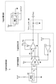
- FIG. 4 is a block diagram of the signal processing circuit shown in FIG. 3.
- (A) is side surface sectional drawing of the piston rod, magnet, and magnetic sensor which are shown in FIG.
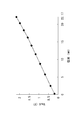
- FIG. 5B is a sectional view taken along the line II in FIG. It is a graph which shows the position of the piston rod with respect to the cylinder tube shown in FIG. 1, and the relationship between Vout.
- FIG. 1 is a side cross-sectional view of a four-joint link knee joint 10 according to the present embodiment when the bending angle of the knee 30 is 0 °.
- FIG. 2 is a side cross-sectional view of the four-joint link knee joint 10 when the knee portion 30 has a bending angle of 90 °.
- FIG. 3 is a block diagram of the four-joint link knee joint 10.
- the four-joint link knee joint 10 has a frame 20, a knee part 30 of the four-joint link mechanism, and the operation of the knee part 30 by generating a drag force using oil as a working fluid.
- a fluid cylinder 40 that is a limiting cylinder, a drive device 50 that changes the characteristics of the fluid cylinder 40, and an expansion / contraction that detects the position of the piston rod 42 relative to the cylinder tube 41 of the fluid cylinder 40 as the expansion / contraction amount of the fluid cylinder 40.
- the position detection device 60 as the amount detection means
- the signal processing circuit 70 for processing the signal output from the position detection device 60
- the drive device 50 the magnitude of the drag force to be generated.
- a battery (not shown) for supplying power.
- the driving device 50, the signal processing circuit 70, the computer 80, and the battery are not shown in FIGS. 1 and 2, but are actually attached to the frame 20 or the fluid cylinder 40.
- the knee 20 is fixed to the frame 20.
- the frame 20 includes a foot connection portion 21 for connecting a pipe of a foot portion (not shown) at an end opposite to the side where the knee portion 30 is provided.
- the frame 20 includes a shaft 22 that rotatably supports the cylinder tube 41.
- the four-joint link knee joint 10 is combined with a foot portion to become a prosthetic leg.
- the knee portion 30 includes an upper link 31 having a thigh connection portion 31a for connecting a thigh socket of a prosthetic leg user, a lower link 32 fixed to the frame 20, an upper link 31 and a lower link. 32, a front link 33 to which 32 is connected, and a rear link 34 to which the upper link 31 and the lower link 32 are connected.
- the upper link 31 includes a shaft 31b that rotatably supports the piston rod 42.
- the lower link 32 includes a shaft 32a that rotatably supports the rear link 34.
- the front link 33 includes a shaft 33 a that rotatably supports the upper link 31 and a shaft 33 b that is rotatably supported by the lower link 32.
- the rear link 34 includes a shaft 34 a that rotatably supports the upper link 31.
- the shaft 31b is disposed above the line connecting the shaft 33a and the shaft 34a.
- a shaft 22 that rotatably supports the cylinder tube 41 is disposed below the frame 20. Therefore, the fluid cylinder 40 is accommodated so that it can expand and contract and swing inside the frame 20.
- the fluid cylinder 40 includes a cylinder tube 41, a piston rod 42 that is movable with respect to the cylinder tube 41, and a piston 43 that is movably accommodated in the cylinder tube 41 and to which the piston rod 42 is fixed.
- the piston rod 42 is made of a nonmagnetic material.
- the piston rod 42 is fixed by sandwiching the magnet 61 in the piston rod 42, a rod body 42a in which a space for accommodating a magnet 61 described later is formed, a rod end 42b fixed to the rod body 42a. Therefore, spacers 42c and 42d adjusted to a predetermined length are provided.
- a female screw is formed on the rod main body 42a.
- the rod end 42b is formed with a male screw combined with the female screw of the rod main body 42a.
- the position detection device 60 includes a magnet 61 housed in the piston rod 42 and a magnetic sensor 62 that is fixed to the cylinder tube 41 and detects the position of the magnet 61.
- the magnet 61 is, for example, an alnico magnet.
- the magnetic sensor 62 is a sensor that detects the position of the magnet 61 based on the magnitude of the magnetic field generated by the magnet 61, and is, for example, a Hall element.
- the piston rod 42 is housed in the rod main body 42a in the order of the spacer 42c, the magnet 61, and the spacer 42d, and then the male screw of the rod end 42b and the female screw of the rod main body 42a are tightened, thereby The magnet 61 is fixed at a predetermined position.
- the computer 80 is, for example, an MCU (Micro Control Unit).
- the computer 80 converts the position detected by the magnetic sensor 62 to bend the four-joint link knee joint 10 with respect to the bending angle of the knee 30, that is, the thigh of the prosthetic leg user connected to the thigh connection 31 a (or (Extension) angle is acquired, and constitutes the angle acquisition means of the present invention.
- FIG. 4 is a block diagram of the signal processing circuit 70.
- the signal processing circuit 70 includes a voltage reference 71a that generates Vref, which is a reference voltage with little temperature change, input to the magnetic sensor 62, from Vcc, which is a power supply voltage from a battery (not shown).
- the reference power supply unit 71, the signal adjustment unit 72 that adjusts VH , which is the output voltage of the magnetic sensor 62, and the output of the signal adjustment unit 72 are corrected for temperature in order to cancel the temperature characteristics of the magnetic sensor 62.
- a temperature correction unit 73 and a filter unit 74 that removes noise from the output of the temperature correction unit 73 are provided.
- the signal adjustment unit 72 includes an amplifier circuit 72a that amplifies VH , and an offset circuit 72b that adds Vref as an offset voltage to the voltage amplified by the amplifier circuit 72a.
- the amplification factor of the amplifier circuit 72a is, for example, 50 times.
- the temperature correction unit 73 includes a resistor 73a having a small electrical resistance temperature change and a PTC (Positive Temperature Coefficient) thermistor 73b whose electrical resistance increases in proportion to the temperature rise.
- the temperature coefficient of the electrical resistance of the resistor 73a is, for example, ⁇ 10 ppm / ° C.
- the temperature coefficient of the electrical resistance of the PTC thermistor 73b is, for example, about 7900 ppm / ° C.
- the temperature coefficient of the electric resistance of the magnetic sensor 62 is, for example, about ⁇ 2000 ppm / ° C.
- Vout is a signal output from the signal processing circuit 70
- V H is the output voltage of the magnetic sensor 62
- GAIN is a gain of the amplifier circuit 72a
- the PTC is an electrical resistance of the PTC thermistor 73b
- the resistor Using R1 that is the electric resistance of the device 73a and Vref that is the offset voltage of the offset circuit 72b it can be expressed as follows.
- Vout (V H ⁇ GAIN) ⁇ (1 + PTC / R1) + Vref ...
- FIG. 5A is a side sectional view of the piston rod 42, the magnet 61, and the magnetic sensor 62.
- FIG. 5B is a cross-sectional view taken along the line II of FIG.
- the magnet 61 has a magnetization direction that is the direction in which the piston rod 42 extends, that is, the direction indicated by the arrow 10a.
- the magnet 61 is a cylindrical magnet having a circular cross section perpendicular to the direction indicated by the arrow 10a.
- the magnet 61 is moved in the direction indicated by the arrow 10a with respect to the magnetic sensor 62 so that the magnetic sensor 62 changes from a position near one end of the magnet 61 to a position near the other end.
- the rate of change of the magnetic field changes abruptly at both ends of the magnet 61, that is, in the vicinity of the magnetic pole of the magnet 61, linearity exists between the position of the magnet 61 relative to the magnetic sensor 62 and the above-described Vout. unacceptable.
- the rate of change of the magnetic field is substantially constant near the central portion of the magnet 61, linearity is recognized between the position of the magnet 61 relative to the magnetic sensor 62 and the above-described Vout.
- the magnet 61 is a fluid cylinder 40 (see FIG. 1) when the bending angle of the knee 30 (see FIG. 1) changes from 0 ° to 90 °, for example. .), That is, a magnet extending in the direction indicated by the arrow 10a longer than the stroke of the fluid cylinder 40 corresponding to the movement range of the knee 30 is used.
- the magnet 61 is about twice as long as the stroke of the fluid cylinder 40 when the bending angle of the knee 30 changes from 0 ° to 90 °.
- the length of the magnet 61 should just be the length which can use the range in which the above-mentioned linearity is recognized, and the fluid cylinder 40 in case the bending angle of the knee part 30 changes from 0 degree to 90 degrees. Need not be about twice as long as the stroke.
- the length of the magnet 61 is It is preferable that the length is set longer with some margin than the minimum length in which the above-described linearity can be used.
- the minimum length in which the above-described linearity can be used varies depending on various conditions such as the strength of the magnetic force of the magnet 61, the shape of the magnet 61, and the distance of the magnetic sensor 62 to the magnet 61.
- the distance 60a between the magnet 61 and the magnetic sensor 62 in the direction orthogonal to the direction indicated by the arrow 10a is designed to be a distance that increases the linearity between the position of the magnet 61 relative to the magnetic sensor 62 and the above-described Vout. Has been.
- FIG. 6 is a graph showing the relationship between the position of the piston rod 42 relative to the cylinder tube 41 and Vout.
- the positions of 0 mm and 22.17 mm are positions where the bending angles of the knee 30 are 0 ° and 90 °, respectively.
- linearity is recognized between the position of the piston rod 42 with respect to the cylinder tube 41, that is, the position of the magnet 61 with respect to the magnetic sensor 62, and Vout.
- Lx which is the position of the piston rod 42 with respect to the cylinder tube 41 is 22.17 mm which is a change in the position of the piston rod 42 with respect to the cylinder tube 41 when the bending angle of the knee 30 changes from 0 ° to 90 °.
- V 0 that is a signal output from the signal processing circuit 70 when the bending angle of the knee 30 is 0 °
- V 0 that is output from the signal processing circuit 70 when the bending angle of the knee 30 is 90 °.
- V 90 is a signal
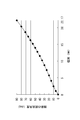
- FIG. 7 is a graph showing the relationship between the position of the piston rod 42 relative to the cylinder tube 41 and the bending angle of the knee 30.
- the relationship between the position of the piston rod 42 relative to the cylinder tube 41 and the bending angle of the knee portion 30 is the structure of the four-joint link knee joint 10, that is, the upper link 31, the lower link 32, and the front portion.
- the distance between the shafts 32a, 33a, 33b, and 34a connecting the link 33 and the rear link 34, the position of the shaft 31b that rotatably supports the piston rod 42, and the cylinder tube 41 are rotatably supported. It is mechanically determined by the position of the shaft 22.
- the relationship between the position of the piston rod 42 relative to the cylinder tube 41 and the bending angle of the knee 30 may be different between the four-joint knee joints 10 having different structures, but the four-joint knee joint having the same structure. 10 is the same.
- Ka which is the bending angle of the knee portion 30, can be expressed as follows using Lx, which is the position of the piston rod 42 with respect to the cylinder tube 41.
- Lx which is the position of the piston rod 42 with respect to the cylinder tube 41.
- Ka 0.0041 ⁇ [22.17 ⁇ (Vout ⁇ V 0 ) / (V 90 ⁇ V 0 )] 3 -0.0773 ⁇ [22.17 ⁇ (Vout ⁇ V 0 ) / (V 90 ⁇ V 0 )] 2 +3.7559 ⁇ [22.17 ⁇ (Vout ⁇ V 0 ) / (V 90 ⁇ V 0 )] +0.98
- the signal processing circuit 70 processes V H that is the output voltage of the magnetic sensor 62 as shown in Expression (1), and inputs Vout to the computer 80.
- the computer 80 changes the characteristics of the fluid cylinder 40 by controlling the operation of the driving device 50 based on the generated Ka.
- the computer 80 may control the operation of the driving device 50 based on information other than Ka.
- the movement of the knee 30 is limited by the fluid cylinder 40. That is, the deformation of the knee 30 is limited by the drag generated by the fluid cylinder 40.
- the four-joint link knee joint 10 is actually made to output V 0 and V 90 from the signal processing circuit 70 in a state where the bending angle of the knee 30 is set to 0 ° and 90 ° for each individual.
- the detection accuracy of the bending angle Ka of the knee 30 shown in Expression (4) can be maintained for each individual. That is, there is a possibility that the position of the magnetic sensor 62 with respect to the magnet 61 is slightly different for each individual four-joint link knee joint 10 when the four-joint link knee joint 10 is manufactured.
- the influence of the individual difference on the detection accuracy of the bending angle Ka of the knee 30 can be suppressed by causing the computer 80 to store the actually output V 0 and V 90 .
- the four-joint link knee joint 10 converts the amount of expansion / contraction of the fluid cylinder 40 that restricts the movement of the knee 30, that is, the position of the piston rod 42 relative to the cylinder tube 41, thereby changing the knee 30. Can be detected. That is, the four-joint link knee joint 10 can detect the bending (or extension) angle of the knee 30 by a method other than the method using the rotation angle sensor. Therefore, the four-joint link knee joint 10 can detect the bending angle of the knee without causing the problem of the sensor installation space and wiring.
- the four-joint knee joint 10 detects the position of the piston rod 42 with respect to the cylinder tube 41 as the amount of expansion and contraction of the fluid cylinder 40 by a magnetic method, so that the position of the piston rod 42 with respect to the cylinder tube 41 is contact-type or optical. Compared with the configuration detected by the formula method, it is possible to reduce the possibility of a decrease in detection accuracy due to contamination caused by use. Furthermore, since the magnet 61 is accommodated in the piston rod 42, the magnet 61 is not damaged or worn by contact with an external force or other portions of the four-joint link knee joint 10.
- the wiring arrangement of the magnetic sensor 62 is compared with the configuration in which the magnetic sensor 62 is accommodated in the piston rod 42. Can be facilitated.
- the four-joint link knee joint 10 optically detects, for example, the outer circumference of the piston rod 42, which is alternately colored in the longitudinal direction, such as white and black, or alternately wears N and S poles.
- the position of the piston rod 42 may be detected by magnetically detecting a magnetized one.
- the cylinder tube 41 may be made non-magnetic, a magnet is built in the piston 43, and a plurality of magnetic sensors may be arranged along the moving direction of the piston 43 to detect the position of the piston 43.
- the position of the piston rod 42 or the piston 43 with respect to the cylinder tube 41 may be detected by a contact type or other optical or magnetic method. That is, it is only necessary to be able to measure the position of the piston rod 42 or the piston 43 with respect to the cylinder tube 41, that is, the amount of expansion / contraction of the fluid cylinder 40 by any method.
- the four-joint knee joint 10 has a magnet 61 extending in the extending direction of the piston rod 42 longer than the stroke of the fluid cylinder 40 when the bending angle of the knee 30 changes from 0 ° to 90 °.
- the magnetization direction of 61 is the extending direction of the piston rod 42, and the magnetic sensor 62 detects the position of the magnet 61 based on the magnitude of the magnetic field generated by the magnet 61. The number of magnets required to detect the position can be reduced to one.
- the four-joint link knee joint 10 Since the cross section orthogonal to the extending direction of the magnet 61 is circular, the four-joint link knee joint 10 has an axis extending in the extending direction of the magnet 61 when the piston rod 42 rotates with respect to the cylinder tube 41. Even if the magnet 61 rotates as the center, a change in the positional relationship between the magnet 61 and the magnetic sensor 62 can be suppressed. Therefore, the four-joint link knee joint 10 does not need to fix the magnet 61 so as not to rotate in the piston rod 42, can simplify the configuration, and decrease the detection accuracy of the position of the piston rod 42 relative to the cylinder tube 41. Can be suppressed.
- the fluid cylinder 40 is connected to the frame 20 and the knee portion 30 when the magnet 61 is incorporated into the piston rod 42.
- the magnet 61 is centered on the axis extending in the extending direction of the magnet 61, compared to the state of the magnet 61 that was planned when assembled. Even if it rotates, the possibility that the positional relationship between the magnet 61 and the magnetic sensor 62 is different from the planned positional relationship can be reduced. Therefore, when the four-joint link knee joint 10 is assembled, it can suppress that the detection accuracy of the position of the piston rod 42 with respect to the cylinder tube 41 falls.
- the magnet 61 may not have a circular cross section perpendicular to the extending direction.
- the magnet 61 when the magnet 61 is fixed so as not to rotate within the piston rod 42, or when the detection accuracy of the position of the piston rod 42 relative to the cylinder tube 41 may be relatively low, the magnet 61 is a cylindrical magnet. Instead, it may be a prismatic magnet.
- the knee mechanism of the present invention is a four-bar link mechanism in the present embodiment, but may be a multi-bar link mechanism other than the four-bar link mechanism.
- the cylinder of the present invention is a fluid cylinder using hydraulic pressure in the present embodiment, but may be a fluid cylinder using a gas such as air.
- the prosthetic leg as a whole is controlled not in the stance phase but in the swing phase, and the fluid cylinder generates a repulsive force (that is, a force assisting extension) instead of the drag, and this repulsive force is generated by the computer. Controlled by.
- the expansion / contraction amount detecting means of the present invention includes a magnet 61 housed in the piston rod 42 and a magnetic sensor 62 that is fixed to the cylinder tube 41 and detects the position of the magnet 61.
- the expansion / contraction amount detecting means of the present invention may be one in which a magnetic sensor is accommodated in the piston rod 42 and a magnet is fixed to the cylinder tube 41.
Landscapes
- Health & Medical Sciences (AREA)
- Transplantation (AREA)
- Vascular Medicine (AREA)
- Life Sciences & Earth Sciences (AREA)
- Oral & Maxillofacial Surgery (AREA)
- Engineering & Computer Science (AREA)
- Biomedical Technology (AREA)
- Heart & Thoracic Surgery (AREA)
- Veterinary Medicine (AREA)
- Cardiology (AREA)
- Animal Behavior & Ethology (AREA)
- General Health & Medical Sciences (AREA)
- Public Health (AREA)
- Orthopedic Medicine & Surgery (AREA)
- Prostheses (AREA)
- Measurement Of Length, Angles, Or The Like Using Electric Or Magnetic Means (AREA)
Description
Vout=(VH×GAIN)×(1+PTC/R1)+Vref
・・・式(1)
Lx=22.17×(Vout-V0)/(V90-V0)・・・式(2)
Ka=0.0041×Lx3-0.0773×Lx2
+3.7559×Lx+0.9886・・・式(3)
Ka=0.0041
×[22.17×(Vout-V0)/(V90-V0)]3
-0.0773
×[22.17×(Vout-V0)/(V90-V0)]2
+3.7559
×[22.17×(Vout-V0)/(V90-V0)]
+0.9886 ・・・式(4)
30 膝部
40 流体シリンダー(シリンダー)
41 シリンダーチューブ
42 ピストンロッド
43 ピストン
60 位置検出装置(伸縮量検出手段)
61 磁石
62 磁気センサー
80 コンピューター(角度取得手段)
Claims (5)
- 多節リンク機構の膝部と、前記膝部の動作を制限または補助するシリンダーと、前記シリンダーの伸縮量を検出する伸縮量検出手段と、前記伸縮量検出手段によって検出された前記伸縮量を変換して前記膝部の屈曲角度を取得する角度取得手段とを備えていることを特徴とする多節リンク膝継手。
- 前記伸縮量検出手段は、磁石と、前記磁石の位置を検出する磁気センサーとを備えており、
前記磁石および前記磁気センサーの一方は、前記シリンダーのピストンロッドに収納されており、
前記磁石および前記磁気センサーの他方は、前記シリンダーのシリンダーチューブに対して固定されており、
前記伸縮量検出手段は、前記伸縮量として、前記シリンダーチューブに対する前記ピストンロッドの位置を前記磁石および前記磁気センサーによって検出することを特徴とする請求項1に記載の多節リンク膝継手。 - 前記磁石は、前記ピストンロッドに収納されており、
前記磁気センサーは、前記シリンダーチューブに対して固定されていることを特徴とする請求項2に記載の多節リンク膝継手。 - 前記磁石は、前記膝部の動作範囲に相当する前記シリンダーのストロークより長く前記ピストンロッドの延在方向に延在しており、磁化方向が前記ピストンロッドの延在方向であり、
前記磁気センサーは、前記磁石が発生させる磁界の大きさによって前記磁石の位置を検出することを特徴とする請求項2または請求項3に記載の多節リンク膝継手。 - 前記磁石は、前記膝部の動作範囲に相当する前記シリンダーのストロークより長く前記ピストンロッドの延在方向に延在しており、磁化方向が前記ピストンロッドの延在方向であり、
前記磁気センサーは、前記磁石が発生させる磁界の大きさによって前記磁石の位置を検出し、
前記磁石は、延在方向に直交する断面が円形であることを特徴とする請求項3に記載の多節リンク膝継手。
Priority Applications (5)
| Application Number | Priority Date | Filing Date | Title |
|---|---|---|---|
| US14/352,843 US9089443B2 (en) | 2012-03-09 | 2012-03-09 | Multi-articulated link knee joint |
| CN201280067789.1A CN104066404B (zh) | 2012-03-09 | 2012-03-09 | 多连杆膝部联结器 |
| EP12870368.3A EP2823791B1 (en) | 2012-03-09 | 2012-03-09 | Multi-articulated link knee joint |
| PCT/JP2012/056196 WO2013132662A1 (ja) | 2012-03-09 | 2012-03-09 | 多節リンク膝継手 |
| JP2013546498A JP5465365B1 (ja) | 2012-03-09 | 2012-03-09 | 多節リンク膝継手 |
Applications Claiming Priority (1)
| Application Number | Priority Date | Filing Date | Title |
|---|---|---|---|
| PCT/JP2012/056196 WO2013132662A1 (ja) | 2012-03-09 | 2012-03-09 | 多節リンク膝継手 |
Publications (1)
| Publication Number | Publication Date |
|---|---|
| WO2013132662A1 true WO2013132662A1 (ja) | 2013-09-12 |
Family
ID=49116173
Family Applications (1)
| Application Number | Title | Priority Date | Filing Date |
|---|---|---|---|
| PCT/JP2012/056196 Ceased WO2013132662A1 (ja) | 2012-03-09 | 2012-03-09 | 多節リンク膝継手 |
Country Status (5)
| Country | Link |
|---|---|
| US (1) | US9089443B2 (ja) |
| EP (1) | EP2823791B1 (ja) |
| JP (1) | JP5465365B1 (ja) |
| CN (1) | CN104066404B (ja) |
| WO (1) | WO2013132662A1 (ja) |
Cited By (5)
| Publication number | Priority date | Publication date | Assignee | Title |
|---|---|---|---|---|
| JP2018187358A (ja) * | 2017-04-28 | 2018-11-29 | ナブテスコ株式会社 | 多節リンク膝継手 |
| JP2019180888A (ja) * | 2018-04-11 | 2019-10-24 | ナブテスコ株式会社 | 多節リンク膝継手 |
| JP2019180887A (ja) * | 2018-04-11 | 2019-10-24 | ナブテスコ株式会社 | 多節リンク膝継手 |
| KR20210006424A (ko) * | 2018-05-09 | 2021-01-18 | 오토 복 헬스케어 프로덕츠 게엠베하 | 교정 보조장치 |
| CN115737222A (zh) * | 2022-12-02 | 2023-03-07 | 重庆文理学院 | 自适应可变瞬心人工膝关节 |
Families Citing this family (14)
| Publication number | Priority date | Publication date | Assignee | Title |
|---|---|---|---|---|
| CN105456087B (zh) * | 2015-11-18 | 2018-08-24 | 广州玖玖伍捌健康科技股份有限公司 | 一种可接入互联网的智能调香设备 |
| CN105769395B (zh) * | 2016-04-12 | 2017-07-18 | 上海理工大学 | 用于智能膝关节的电控液压阻尼缸结构 |
| KR101889656B1 (ko) * | 2017-05-23 | 2018-08-17 | 근로복지공단 | 작동인식 가능한 대퇴의지 |
| EP3821220B1 (en) | 2018-08-22 | 2024-11-13 | University of Utah Research Foundation | Force and torque sensor for prosthetic and orthopedic devices |
| US12070398B2 (en) | 2018-08-28 | 2024-08-27 | University Of Utah Research Foundation | Variable transmission for assistive prosthesis device |
| JP7347930B2 (ja) | 2018-12-25 | 2023-09-20 | ナブテスコ株式会社 | 分析システムおよび情報記録方法 |
| CN110711054A (zh) * | 2019-08-03 | 2020-01-21 | 苏州自如医疗器械有限公司 | 一种基于磁流变阻尼器的假肢膝关节 |
| RU2731310C1 (ru) * | 2019-11-28 | 2020-09-01 | Федеральное государственное бюджетное образовательное учреждение высшего образования "Северо-Осетинская государственная медицинская академия" Министерства здравоохранения Российской Федерации | Ортопедический демпфер для ортезов коленного сустава |
| JP7526570B2 (ja) | 2020-03-06 | 2024-08-01 | ナブテスコ株式会社 | 状態推定装置、制御弁、状態推定プログラム、および状態推定方法 |
| JP7526571B2 (ja) | 2020-03-06 | 2024-08-01 | ナブテスコ株式会社 | 状態推定装置、制御弁、状態推定プログラム、および状態推定方法 |
| JP7460399B2 (ja) | 2020-03-06 | 2024-04-02 | ナブテスコ株式会社 | 状態推定装置、制御弁、状態推定プログラム、および状態推定方法 |
| JP7584897B2 (ja) | 2020-03-06 | 2024-11-18 | ナブテスコ株式会社 | 状態推定装置、状態推定プログラム、および状態推定方法 |
| JP7716113B2 (ja) | 2020-03-20 | 2025-07-31 | ユニバーシティ オブ ユタ リサーチ ファウンデーション | 受動型および動力付き外骨格における自己整列機構 |
| US12427041B1 (en) * | 2024-03-25 | 2025-09-30 | Ken Dall Enterprise Co., Ltd. | Knee joint structure featuring hydraulic control |
Citations (7)
| Publication number | Priority date | Publication date | Assignee | Title |
|---|---|---|---|---|
| JPH05212070A (ja) * | 1991-12-05 | 1993-08-24 | Otto Bock Orthopaed Ind Besitz & Verwalt Kg | 義足制御システム |
| JP2000139974A (ja) | 1998-11-06 | 2000-05-23 | Nabco Ltd | 多節リンクの膝関節を備える義足 |
| US6113642A (en) * | 1996-06-27 | 2000-09-05 | Mauch, Inc. | Computer controlled hydraulic resistance device for a prosthesis and other apparatus |
| JP2001514925A (ja) * | 1997-08-15 | 2001-09-18 | チャス・エイ・ブラッチフォード アンド サンズ リミテッド | 下肢部義足 |
| JP2002533161A (ja) * | 1998-12-24 | 2002-10-08 | ビーダーマン・モテーク・ゲゼルシャフト・ミット・ベシュレンクタ・ハフツング | 人工膝関節を備える脚用人工装具および脚用人工装具を制御するための方法 |
| JP2004167106A (ja) | 2002-11-21 | 2004-06-17 | Nabco Ltd | 柔軟なひざ制動機能をもつ義足 |
| JP2004249102A (ja) * | 2003-02-17 | 2004-09-09 | Eska Implants Gmbh & Co | 大腿義足 |
Family Cites Families (4)
| Publication number | Priority date | Publication date | Assignee | Title |
|---|---|---|---|---|
| GB9312131D0 (en) | 1993-06-11 | 1993-07-28 | Blatchford & Sons Ltd | Prosthesis control system |
| JP2001221653A (ja) * | 1999-12-01 | 2001-08-17 | Honda Motor Co Ltd | 変位検出装置 |
| US20080127711A1 (en) * | 2006-12-04 | 2008-06-05 | Farag Tarek A Z | Force and Torque Measurements with Calibration and Auto Scale |
| CA2723015C (en) * | 2008-04-30 | 2016-07-19 | Rizzoli Ortopedia S.P.A. | Automatic prosthesis for above-knee amputees |
-
2012
- 2012-03-09 EP EP12870368.3A patent/EP2823791B1/en active Active
- 2012-03-09 WO PCT/JP2012/056196 patent/WO2013132662A1/ja not_active Ceased
- 2012-03-09 US US14/352,843 patent/US9089443B2/en active Active
- 2012-03-09 CN CN201280067789.1A patent/CN104066404B/zh active Active
- 2012-03-09 JP JP2013546498A patent/JP5465365B1/ja active Active
Patent Citations (7)
| Publication number | Priority date | Publication date | Assignee | Title |
|---|---|---|---|---|
| JPH05212070A (ja) * | 1991-12-05 | 1993-08-24 | Otto Bock Orthopaed Ind Besitz & Verwalt Kg | 義足制御システム |
| US6113642A (en) * | 1996-06-27 | 2000-09-05 | Mauch, Inc. | Computer controlled hydraulic resistance device for a prosthesis and other apparatus |
| JP2001514925A (ja) * | 1997-08-15 | 2001-09-18 | チャス・エイ・ブラッチフォード アンド サンズ リミテッド | 下肢部義足 |
| JP2000139974A (ja) | 1998-11-06 | 2000-05-23 | Nabco Ltd | 多節リンクの膝関節を備える義足 |
| JP2002533161A (ja) * | 1998-12-24 | 2002-10-08 | ビーダーマン・モテーク・ゲゼルシャフト・ミット・ベシュレンクタ・ハフツング | 人工膝関節を備える脚用人工装具および脚用人工装具を制御するための方法 |
| JP2004167106A (ja) | 2002-11-21 | 2004-06-17 | Nabco Ltd | 柔軟なひざ制動機能をもつ義足 |
| JP2004249102A (ja) * | 2003-02-17 | 2004-09-09 | Eska Implants Gmbh & Co | 大腿義足 |
Non-Patent Citations (1)
| Title |
|---|
| See also references of EP2823791A4 * |
Cited By (13)
| Publication number | Priority date | Publication date | Assignee | Title |
|---|---|---|---|---|
| JP2018187358A (ja) * | 2017-04-28 | 2018-11-29 | ナブテスコ株式会社 | 多節リンク膝継手 |
| US10893958B2 (en) | 2017-04-28 | 2021-01-19 | Nabtesco Corporation | Multi-articulated link knee joint |
| JP7016726B2 (ja) | 2017-04-28 | 2022-02-07 | ナブテスコ株式会社 | 多節リンク膝継手 |
| JP7203509B2 (ja) | 2018-04-11 | 2023-01-13 | ナブテスコ株式会社 | 多節リンク膝継手 |
| JP2019180888A (ja) * | 2018-04-11 | 2019-10-24 | ナブテスコ株式会社 | 多節リンク膝継手 |
| JP2019180887A (ja) * | 2018-04-11 | 2019-10-24 | ナブテスコ株式会社 | 多節リンク膝継手 |
| US11058558B2 (en) | 2018-04-11 | 2021-07-13 | Nabtesco Corporation | Multi-articulated link knee joint |
| US12042406B2 (en) | 2018-04-11 | 2024-07-23 | Nabtesco Corporation | Multi-articulated link knee joint |
| JP7199155B2 (ja) | 2018-04-11 | 2023-01-05 | ナブテスコ株式会社 | 多節リンク膝継手 |
| KR20210006424A (ko) * | 2018-05-09 | 2021-01-18 | 오토 복 헬스케어 프로덕츠 게엠베하 | 교정 보조장치 |
| KR102523542B1 (ko) * | 2018-05-09 | 2023-04-19 | 오토 복 헬스케어 프로덕츠 게엠베하 | 교정 보조장치 |
| JP2021522514A (ja) * | 2018-05-09 | 2021-08-30 | オットー・ボック・ヘルスケア・プロダクツ・ゲーエムベーハー | 整形外科補助手段 |
| CN115737222A (zh) * | 2022-12-02 | 2023-03-07 | 重庆文理学院 | 自适应可变瞬心人工膝关节 |
Also Published As
| Publication number | Publication date |
|---|---|
| JPWO2013132662A1 (ja) | 2015-07-30 |
| US9089443B2 (en) | 2015-07-28 |
| CN104066404A (zh) | 2014-09-24 |
| CN104066404B (zh) | 2015-07-29 |
| JP5465365B1 (ja) | 2014-04-09 |
| EP2823791B1 (en) | 2016-09-28 |
| EP2823791A1 (en) | 2015-01-14 |
| EP2823791A4 (en) | 2015-05-06 |
| US20150032228A1 (en) | 2015-01-29 |
Similar Documents
| Publication | Publication Date | Title |
|---|---|---|
| JP5465365B1 (ja) | 多節リンク膝継手 | |
| CN112888535B (zh) | 集成关节及机器人 | |
| EP3186131B1 (en) | Low-height sensor for measuring torque angle | |
| US20180298973A1 (en) | Magneto-rheological series elastic actuator | |
| JP6861513B2 (ja) | ステアリングホイール回転情報確定装置及びステアリングホイール回転情報確定方法 | |
| KR20140002507A (ko) | 역각 센서 및 역각 센서를 구비한 로봇 암 | |
| EP3415873B1 (en) | Rotational structure, assist system, and robot | |
| JP2016061302A (ja) | アクチュエータ装置、パワーアシストロボットおよびヒューマノイドロボット | |
| CA2395722A1 (en) | Angle sensor for orthopedic rehabilitation device | |
| US11058558B2 (en) | Multi-articulated link knee joint | |
| JP2006502381A5 (ja) | ||
| US20250334460A1 (en) | Force and torque sensor for prosthetic and orthopedic devices | |
| KR20060115649A (ko) | 리드 및 풀 보상을 갖는 조향 시스템 | |
| CN101644610A (zh) | 压力传感器 | |
| CN107209027A (zh) | 位置传感器组件 | |
| CN107443381A (zh) | 一种弹性驱动关节的力矩寻零方法 | |
| ES2824202T3 (es) | Aparato de entrenamiento y método no terapéutico para corregir la magnitud de la fuerza | |
| WO2021189676A1 (zh) | 刚度主动控制的末段肢杆及包含该末段肢杆的仿生机器人 | |
| CN102670382B (zh) | 一种辅助行走的智能拐杖系统 | |
| JP7016726B2 (ja) | 多節リンク膝継手 | |
| CN107943123A (zh) | 一种力促动器的控制系统和控制方法 | |
| CN215486184U (zh) | 一种汽轮机调门控制系统 | |
| JP2025063581A (ja) | 力検出装置、及びロボット | |
| CN121612148A (zh) | 一种灵巧手、直线位置的测量装置及其控制方法 | |
| CN120095877A (zh) | 关节模组和灵巧手 |
Legal Events
| Date | Code | Title | Description |
|---|---|---|---|
| ENP | Entry into the national phase |
Ref document number: 2013546498 Country of ref document: JP Kind code of ref document: A |
|
| 121 | Ep: the epo has been informed by wipo that ep was designated in this application |
Ref document number: 12870368 Country of ref document: EP Kind code of ref document: A1 |
|
| WWE | Wipo information: entry into national phase |
Ref document number: 14352843 Country of ref document: US |
|
| REEP | Request for entry into the european phase |
Ref document number: 2012870368 Country of ref document: EP |
|
| WWE | Wipo information: entry into national phase |
Ref document number: 2012870368 Country of ref document: EP |
|
| NENP | Non-entry into the national phase |
Ref country code: DE |