WO2013132884A1 - タイヤ形成用の剛性中子 - Google Patents
タイヤ形成用の剛性中子 Download PDFInfo
- Publication number
- WO2013132884A1 WO2013132884A1 PCT/JP2013/050546 JP2013050546W WO2013132884A1 WO 2013132884 A1 WO2013132884 A1 WO 2013132884A1 JP 2013050546 W JP2013050546 W JP 2013050546W WO 2013132884 A1 WO2013132884 A1 WO 2013132884A1
- Authority
- WO
- WIPO (PCT)
- Prior art keywords
- core
- tire
- surface portion
- core body
- mating
- Prior art date
- Legal status (The legal status is an assumption and is not a legal conclusion. Google has not performed a legal analysis and makes no representation as to the accuracy of the status listed.)
- Ceased
Links
Images



Classifications
-
- B—PERFORMING OPERATIONS; TRANSPORTING
- B29—WORKING OF PLASTICS; WORKING OF SUBSTANCES IN A PLASTIC STATE IN GENERAL
- B29D—PRODUCING PARTICULAR ARTICLES FROM PLASTICS OR FROM SUBSTANCES IN A PLASTIC STATE
- B29D30/00—Producing pneumatic or solid tyres or parts thereof
- B29D30/06—Pneumatic tyres or parts thereof (e.g. produced by casting, moulding, compression moulding, injection moulding, centrifugal casting)
- B29D30/0601—Vulcanising tyres; Vulcanising presses for tyres
- B29D30/0661—Rigid cores therefor, e.g. annular or substantially toroidal cores
-
- B—PERFORMING OPERATIONS; TRANSPORTING
- B29—WORKING OF PLASTICS; WORKING OF SUBSTANCES IN A PLASTIC STATE IN GENERAL
- B29D—PRODUCING PARTICULAR ARTICLES FROM PLASTICS OR FROM SUBSTANCES IN A PLASTIC STATE
- B29D30/00—Producing pneumatic or solid tyres or parts thereof
- B29D30/06—Pneumatic tyres or parts thereof (e.g. produced by casting, moulding, compression moulding, injection moulding, centrifugal casting)
- B29D30/08—Building tyres
- B29D30/10—Building tyres on round cores, i.e. the shape of the core is approximately identical with the shape of the completed tyre
- B29D30/12—Cores
Definitions
- the present invention relates to a rigid core for forming a tire that can prevent rubber biting between core segments and deterioration of the roundness of a core body during vulcanization.
- the rigid core includes a core body having an outer shape that matches the shape of the tire lumen surface of the vulcanized tire.
- a raw tire is formed by affixing tire constituent members sequentially on the core body. Then, this green tire is put together with the rigid core into the vulcanization mold. Thus, the green tire is sandwiched between the core body that is the inner mold and the vulcanization mold that is the outer mold, and is vulcanized.
- the core body a is composed of a plurality of core segments c that are divided in the circumferential direction so as to be disassembled and removed from the tire after vulcanization molding. And each core segment c makes the circumferential end surface the mating surface cs, and the core main body is formed in an annular shape by mating the mating surfaces cs and cs adjacent to each other in the circumferential direction.
- each mating surface cs is formed in a planar shape.
- the entire surface of the mating surface cs is configured to contact the mating surface cs of the adjacent core segment c. For this reason, when the flatness of the mating surface cs is poor, there arises a problem that the roundness of the core body a is lowered, or a gap is generated between the mating surfaces cs to cause rubber engagement.
- the core body a rises in temperature from a normal temperature state (about 15 to 50 ° C.) at the time of green tire formation to a high temperature state (100 ° C. or more) at the time of vulcanization molding, and the circumference of the tread portion is the bead portion. Longer than the circumference.
- the thermal expansion amount increases on the tread side, but decreases on the bead side, so that the mating surface cs during vulcanization may be complexly deformed in a wavy shape and the flatness may be significantly reduced.
- the occurrence of gaps between the mating surfaces cs tends to increase, or the gaps between the mating surfaces cs tend to increase.
- the force becomes non-uniform and the roundness of the core body a is likely to be lowered.
- the present invention is based on the principle that at least one of the adjacent mating surfaces is a stepped mating surface composed of an edge surface along the outer peripheral edge and a recessed surface portion recessed in a step shape from the edge surface. It is an object of the present invention to provide a rigid core for forming a tire that can effectively suppress the occurrence of rubber biting and the deterioration of the roundness of a core body during vulcanization.
- the invention of claim 1 of the present application includes an annular core body having a tire molding surface portion forming a green tire on the outer surface, and is put into the vulcanization mold together with the green tire.
- Each core segment has both end surfaces in the circumferential direction as mating surfaces, and the mating surfaces adjacent to each other in the circumferential direction form the core body, and at least of the mating surfaces adjacent in the circumferential direction.
- the next mating surface is Border It is characterized by contacting only surface.
- the border surface portion has a width W from the outer peripheral edge of 5 to 35 mm.
- the concave surface portion has a depth H from the edge surface portion of 0.05 to 1.0 mm.
- the core segment of the rigid core according to the present invention has a stepped portion comprising at least one of the adjacent mating surfaces in the circumferential direction, a rimmed surface portion along the outer peripheral edge of the mating surface, and a concave surface portion recessed in a step shape from the rimmed surface portion. It is a mating surface. Therefore, in the assembled state of the core segment, the mating surfaces are in contact with each other only at the edging surface portion. As a result, the core segment is less affected by the flatness than when contacting the entire mating surface, and the matching between the mating surfaces can be improved.
- the rigid core of the present invention can effectively suppress the occurrence of rubber biting during vulcanization and the deterioration of the roundness of the core body during vulcanization.
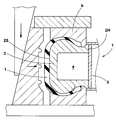
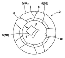
- FIG. 1 It is sectional drawing which shows the use condition of one Example of the rigid core of this invention. It is a perspective view of a core main body. It is a side view of a core main body.
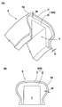
- (A) is a perspective view of a core segment showing a stepped mating surface
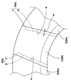
- (B) is a front view of the stepped mating surface. It is a side view which expands and shows the butt
- (A)-(D) are schematic diagrams showing combinations of stepped mating surfaces.
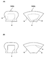
- (A), (B) is the schematic which shows the state of the lumen
- FIG. (A) is a side view of a core main body
- (B) is a perspective view of a core segment.
- the rigid core 1 of the present embodiment includes an annular core body 2 having a tire molding surface portion 2S on the outer surface. Then, tire constituent members such as a carcass ply, a belt ply, a sidewall rubber, and a tread rubber are sequentially pasted on the tire molding surface portion 2S, thereby forming a green tire t having substantially the same shape as the finished tire. The raw tire t is put into the vulcanization mold b together with the rigid core 1 as in the conventional case.
- the green tire t is heated and pressurized between the core body 2 which is an inner mold and the vulcanization mold b which is an outer mold, and vulcanization molding is performed.
- the tire molding surface portion 2S is formed in substantially the same shape as the inner surface shape of the finished tire.
- the rigid core 1 is configured to include an annular core body 2 and a cylindrical core 3 inserted into the center hole 2H.
- the configuration other than the core body 2 is well known. A structure can be adopted as appropriate. Accordingly, only the core body 2 will be described below.
- the core body 2 of the present example is formed in a hollow shape with a lumen 4 extending continuously in the circumferential direction.
- heating means such as an electric heater for heating the raw tire t inside is disposed.
- the core body 2 is formed of a plurality of core segments 5 divided in the circumferential direction, as shown in FIGS.
- Each core segment 5 has both end surfaces in the circumferential direction as mating surfaces 6 and the mating surfaces 6 and 6 adjacent in the circumferential direction are attached to each other to form the annular core body 2.
- the core segment 5 includes first and second core segments 5A and 5B that are alternately arranged in the circumferential direction.
- first core segment 5A the mating surfaces 6 at both ends in the circumferential direction are inclined in such a direction that the circumferential width decreases toward the inside in the radial direction.
- second core segment 5B the mating surfaces 6 at both ends in the circumferential direction are inclined in a direction in which the circumferential width increases inward in the radial direction.
- the core 3 (shown in FIG. 1) prevents the core segments 5 from moving inward in the radial direction and connects the core segments 5 together.
- the edge surface part which follows at least one mating surface 6 of the mating surfaces 6 and 6 adjacent in the circumferential direction along the outer periphery 6e of the mating surface 6 7 and a stepped mating surface 9 which is surrounded by the rimming surface portion 7 and is formed by a stepped concave portion 8 from the rimming surface portion 7.
- the stepped mating surface 9 can contact the mating surface 6 of the adjacent core segment 5 only by the edging surface portion 7.
- the stepped mating surface 9 ensures high matching between the mating surfaces 6 and 6 because the concave surface portion 8 does not contact even if the mating surface 6 of the adjacent core segment 5 is complicatedly deformed by thermal expansion. can do. Therefore, the rigid core 1 of the present invention can effectively suppress the occurrence of rubber biting during vulcanization and the deterioration of the roundness of the core body during vulcanization.
- the rimmed surface portion 7 has a width W from the outer peripheral edge 6e of 5 to 35 mm.
- the width W of the rimming surface portion 7 exceeds 35 mm, the contact area is large, and it becomes difficult to ensure the consistency. For this reason, the rigid core 1 may have a reduced effect of suppressing rubber biting and roundness reduction.
- the width W of the rimming surface portion 7 is less than 5 mm, the strength of the rimming surface portion 7 is reduced and the pressure on the rimming surface portion 7 is also relatively increased. For this reason, durability performance of the rigid core 1 is lowered, and there is a possibility that the edging surface portion 7 is deformed or damaged.
- the depth H from the rimmed surface portion 7 is preferably 0.05 to 1.0 mm. If the depth H from the edging surface portion 7 is less than 0.05 mm, the deformation of the mating surface 6 due to thermal expansion cannot be sufficiently absorbed, and it becomes difficult to ensure high consistency. On the contrary, if the depth H from the rimming surface portion 7 exceeds 1.0 mm, the durability performance deteriorates, for example, the strength of the rimming surface portion 7 decreases, and the rimming surface portion 7 may be deformed or damaged.
- the width W and the depth H of the edging surface portion 7 are more preferably constant, but may not be constant.
- the upper limit value and the lower limit value thereof preferably fall within the ranges of 5 to 35 mm and 0.05 to 1.0 mm, respectively.
- the ratio S1 / S2 is preferably 55% or less, more preferably 35% or less, from the viewpoint of improving the suppression effect.
- profile area S2 means the area enclosed with the outline (outer periphery) of the mating surface 6.
- the stepped mating surface 9 may be formed on at least one of the circumferentially adjacent mating surfaces 6, 6.
- the stepped mating surface 9 may be formed in the following modes (A) to (D). .
- the mating surfaces 6 and 6 of the second core segment 5B are made smooth mating surfaces 10, respectively, and the mating surfaces 6 and 6 of the first core segment 5A are stepped. The mating surface 9 is used.
- the inner cavity portion 4 can be formed without being opened at the mating surface 6 by being closed inside each core segment 5.
- a heating fluid such as steam can be adopted as the heating means, and the raw tire t is heated inside through the core body 2 by flowing this heating fluid into each lumen 4.
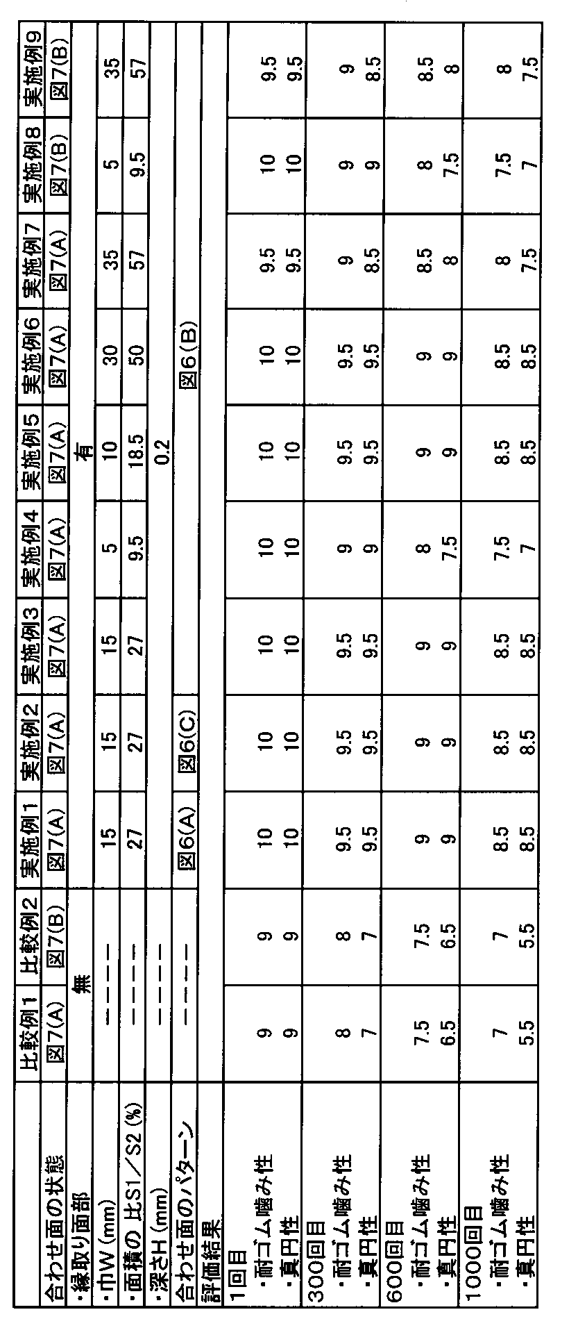
- a core body for forming a pneumatic tire having a tire size of 195 / 65R15 was prototyped based on the specifications shown in Table 1. And the rubber biting resistance when forming a pneumatic tire using this core main body, and the roundness of the core main body were evaluated.
- the specifications are substantially the same except for the specifications listed in Table 1. Further, the width W and the depth H of the edging surface portion are set to be constant.
- Rubber chewing resistance After vulcanization molding, the amount of rubber bite generated between the core segments was measured and evaluated by the 10-point method. The larger the value, the less the rubber bite and the better the rubber bite resistance. The rubber chewing resistance was evaluated at the first, 300th, 600th and 1000th vulcanization moldings, and the change in the rubber chewing resistance with an increase in the number of vulcanization moldings was also evaluated.
- roundness of the core body The core body was slowly rotated around its axis, and the change in irregularities on the outer peripheral surface of the core body at the equator position was measured using a dial gauge and evaluated by a 10-point method. The larger the value, the less the irregularity changes, and the better the roundness accuracy.
- the roundness was measured at the first, 300th, 600th, and 1000th vulcanization moldings, and the change in roundness with an increase in the number of vulcanization moldings was also evaluated.
- the roundness at the 600th time means the roundness of the core body measured when the segment is taken out from the tire and the rigid core is reassembled at room temperature after the vulcanization at the 600th time.
- the rigid cores of the examples can improve the consistency between the core segments by making the mating surfaces into stepped mating surfaces, and improve the rubber biting resistance and roundness. It can be confirmed that
Landscapes
- Engineering & Computer Science (AREA)
- Mechanical Engineering (AREA)
- Moulds For Moulding Plastics Or The Like (AREA)
- Heating, Cooling, Or Curing Plastics Or The Like In General (AREA)
- Tyre Moulding (AREA)
Abstract
Description
2 中子本体
2S タイヤ成形面部
5 中子セグメント
6 合わせ面
6e 外周縁
7 縁取り面部
8 凹み面部
9 段付き合わせ面
b 加硫金型
t 生タイヤ
図1に示すように、本実施形態の剛性中子1は、外表面にタイヤ成形面部2Sを有する環状の中子本体2を具える。そして、このタイヤ成形面部2S上に、カーカスプライ、ベルトプライ、サイドウォールゴム、トレッドゴム等のタイヤ構成部材が順次貼り付けられることにより、仕上がりタイヤとほぼ同形状の生タイヤtが形成される。また、生タイヤtは、従来と同様に、剛性中子1ごと加硫金型b内に投入される。これにより、生タイヤtは、内型である中子本体2と、外型である加硫金型bとの間で加熱加圧され、加硫成形が行われる。なお、タイヤ成形面部2Sは、仕上がりタイヤの内面形状とほぼ同形状に形成される。
(A) 図6(A)に示すように、第2の中子セグメント5Bの合わせ面6、6をそれぞれ段付き合わせ面9とし、第1中子セグメント5Aの合わせ面6、6をそれぞれ凹み面部8のない従来的な平滑な合わせ面10で形成する。
(B) 図6(B)に示すように、第2中子セグメント5Bの合わせ面6、6をそれぞれ平滑な合わせ面10とし、第1中子セグメント5Aの合わせ面6、6をそれぞれ段付き合わせ面9で形成する。
(C) 図6(C)に示すように、第1、第2の中子セグメント5A、5Bの合わせ面6、6のうち、周方向の一方向側(本例では右側)の合わせ面6のみ段付き合わせ面9で形成する。
(D) 図6(D)に示すように、第1、第2の中子セグメント5A、5Bの合わせ面6、6の全てを段付き合わせ面9で形成する。
加硫成形後に、中子セグメント間で発生したゴム噛みのゴム量を測定し、10点法にて評価した。数値が大きいほどゴム噛みが少なく、耐ゴム噛み性に優れている。なお、耐ゴム噛み性の評価は、加硫成形の1回目、300回目、600回目、1000回目にて行い、加硫成形回数の増加に伴う耐ゴム噛み性の変化も評価した。
中子本体をその軸心周りでゆっくりと回転させ、赤道位置において中子本体の外周面での凹凸の変化を、ダイヤルゲージを用いて測定し、10点法にて評価した。数値が大きいほど凹凸の変化が少なく、真円精度に優れている。また、真円性は、加硫成形の1回目、300回目、600回目、1000回目にて行い、加硫成形回数の増加に伴う真円性の変化も評価した。例えば、600回目の真円性とは、600回目の加硫終了後に、セグメントをタイヤから取り出して、常温で剛性中子を再組立てした時に測定した中子本体の真円性を意味する。

Claims (3)
- 生タイヤを形成するタイヤ成形面部を外表面に有する環状の中子本体を具え、かつ生タイヤごと加硫金型内に投入されることにより、該加硫金型と中子本体との間で前記生タイヤを加硫成形する剛性中子であって、
前記中子本体は、周方向に分割される複数の中子セグメントからなり、
各中子セグメントは、その周方向両端面を合わせ面とし、周方向で隣り合う合わせ面同士を互いに付き合わすことにより前記中子本体を形成するとともに、
前記周方向で隣り合う合わせ面の少なくとも一方の合わせ面を、その外周縁に沿う縁取り面部と、この縁取り面部に囲まれかつ該縁取り面部からステップ状に凹む凹み面部とからなる段付き合わせ面とすることにより、隣の合わせ面とは前記縁取り面部のみで接触させることを特徴とするタイヤ形成用の剛性中子。 - 前記縁取り面部は、前記外周縁からの巾Wが5~35mmであることを特徴とする請求項1記載のタイヤ形成用の剛性中子。
- 前記凹み面部は、前記縁取り面部からの深さHが0.05~1.0mmであることを特徴とする請求項1又は2記載のタイヤ形成用の剛性中子。
Priority Applications (3)
| Application Number | Priority Date | Filing Date | Title |
|---|---|---|---|
| US14/379,142 US9039399B2 (en) | 2012-03-07 | 2013-01-15 | Rigid core for forming tire |
| EP13758042.9A EP2823955B1 (en) | 2012-03-07 | 2013-01-15 | Rigid core for forming a tire |
| CN201380010452.1A CN104136205B (zh) | 2012-03-07 | 2013-01-15 | 用于形成轮胎的刚性芯 |
Applications Claiming Priority (2)
| Application Number | Priority Date | Filing Date | Title |
|---|---|---|---|
| JP2012-050744 | 2012-03-07 | ||
| JP2012050744A JP5486622B2 (ja) | 2012-03-07 | 2012-03-07 | タイヤ形成用の剛性中子 |
Publications (1)
| Publication Number | Publication Date |
|---|---|
| WO2013132884A1 true WO2013132884A1 (ja) | 2013-09-12 |
Family
ID=49116371
Family Applications (1)
| Application Number | Title | Priority Date | Filing Date |
|---|---|---|---|
| PCT/JP2013/050546 Ceased WO2013132884A1 (ja) | 2012-03-07 | 2013-01-15 | タイヤ形成用の剛性中子 |
Country Status (5)
| Country | Link |
|---|---|
| US (1) | US9039399B2 (ja) |
| EP (1) | EP2823955B1 (ja) |
| JP (1) | JP5486622B2 (ja) |
| CN (1) | CN104136205B (ja) |
| WO (1) | WO2013132884A1 (ja) |
Cited By (1)
| Publication number | Priority date | Publication date | Assignee | Title |
|---|---|---|---|---|
| CN106029321A (zh) * | 2014-03-07 | 2016-10-12 | 住友橡胶工业株式会社 | 轮胎形成用的刚性型芯及使用该刚性型芯的轮胎制造方法 |
Families Citing this family (2)
| Publication number | Priority date | Publication date | Assignee | Title |
|---|---|---|---|---|
| JP6242146B2 (ja) * | 2013-10-10 | 2017-12-06 | 住友ゴム工業株式会社 | タイヤ形成用の剛性中子、及びそれを用いたタイヤ製造方法 |
| JP6463102B2 (ja) * | 2014-12-01 | 2019-01-30 | 住友ゴム工業株式会社 | タイヤ形成用の剛性中子 |
Citations (6)
| Publication number | Priority date | Publication date | Assignee | Title |
|---|---|---|---|---|
| JP2003340824A (ja) * | 2002-05-27 | 2003-12-02 | Bridgestone Corp | タイヤの加硫成型方法およびタイヤ成形用金型 |
| JP2006117115A (ja) * | 2004-10-21 | 2006-05-11 | Toyota Motor Corp | 空気入りタイヤ |
| JP2006347177A (ja) * | 2005-06-17 | 2006-12-28 | Soc De Technol Michelin | コアの冷却装置及び方法 |
| JP2007152957A (ja) * | 2005-12-02 | 2007-06-21 | Goodyear Tire & Rubber Co:The | タイヤ製造用コアのラッチ機構および移動機構 |
| JP2011161896A (ja) | 2010-02-15 | 2011-08-25 | Sumitomo Rubber Ind Ltd | 空気入りタイヤの製造方法、及びそれに用いる剛性中子 |
| JP2011167979A (ja) | 2010-02-19 | 2011-09-01 | Sumitomo Rubber Ind Ltd | 空気入りタイヤの製造方法 |
Family Cites Families (11)
| Publication number | Priority date | Publication date | Assignee | Title |
|---|---|---|---|---|
| US1735896A (en) * | 1929-11-19 | Collapsible cobs structure | ||
| US1343504A (en) * | 1920-06-15 | Collapsible core | ||
| US1366750A (en) * | 1920-04-08 | 1921-01-25 | Smith Fred | Tire-casing core |
| US1784960A (en) * | 1925-06-12 | 1930-12-16 | Nat Rubber Machinery Co | Collapsible core |
| JP4373160B2 (ja) * | 2003-08-21 | 2009-11-25 | 株式会社ブリヂストン | タイヤ製造用コア |
| WO2005053942A1 (en) * | 2003-11-28 | 2005-06-16 | Pirelli Pneumatici S.P.A. | Process for manufacturing a tyre and toroidal support for carrying out said process |
| US20070023967A1 (en) | 2005-06-17 | 2007-02-01 | Michelin Recherche Et Technique S.A. | Device and process for cooling a core |
| JP5406701B2 (ja) * | 2009-12-25 | 2014-02-05 | 住友ゴム工業株式会社 | タイヤ加硫用の剛性中子 |
| JP5444385B2 (ja) * | 2012-01-18 | 2014-03-19 | 住友ゴム工業株式会社 | タイヤ形成用の剛性中子 |
| JP5698694B2 (ja) * | 2012-03-19 | 2015-04-08 | 住友ゴム工業株式会社 | タイヤ形成用の剛性中子 |
| JP5667606B2 (ja) * | 2012-07-30 | 2015-02-12 | 住友ゴム工業株式会社 | タイヤ形成用の剛性中子 |
-
2012
- 2012-03-07 JP JP2012050744A patent/JP5486622B2/ja not_active Expired - Fee Related
-
2013
- 2013-01-15 WO PCT/JP2013/050546 patent/WO2013132884A1/ja not_active Ceased
- 2013-01-15 US US14/379,142 patent/US9039399B2/en active Active
- 2013-01-15 CN CN201380010452.1A patent/CN104136205B/zh not_active Expired - Fee Related
- 2013-01-15 EP EP13758042.9A patent/EP2823955B1/en not_active Not-in-force
Patent Citations (6)
| Publication number | Priority date | Publication date | Assignee | Title |
|---|---|---|---|---|
| JP2003340824A (ja) * | 2002-05-27 | 2003-12-02 | Bridgestone Corp | タイヤの加硫成型方法およびタイヤ成形用金型 |
| JP2006117115A (ja) * | 2004-10-21 | 2006-05-11 | Toyota Motor Corp | 空気入りタイヤ |
| JP2006347177A (ja) * | 2005-06-17 | 2006-12-28 | Soc De Technol Michelin | コアの冷却装置及び方法 |
| JP2007152957A (ja) * | 2005-12-02 | 2007-06-21 | Goodyear Tire & Rubber Co:The | タイヤ製造用コアのラッチ機構および移動機構 |
| JP2011161896A (ja) | 2010-02-15 | 2011-08-25 | Sumitomo Rubber Ind Ltd | 空気入りタイヤの製造方法、及びそれに用いる剛性中子 |
| JP2011167979A (ja) | 2010-02-19 | 2011-09-01 | Sumitomo Rubber Ind Ltd | 空気入りタイヤの製造方法 |
Non-Patent Citations (1)
| Title |
|---|
| See also references of EP2823955A4 |
Cited By (2)
| Publication number | Priority date | Publication date | Assignee | Title |
|---|---|---|---|---|
| CN106029321A (zh) * | 2014-03-07 | 2016-10-12 | 住友橡胶工业株式会社 | 轮胎形成用的刚性型芯及使用该刚性型芯的轮胎制造方法 |
| CN106029321B (zh) * | 2014-03-07 | 2019-01-04 | 住友橡胶工业株式会社 | 轮胎形成用的刚性型芯及使用该刚性型芯的轮胎制造方法 |
Also Published As
| Publication number | Publication date |
|---|---|
| EP2823955A1 (en) | 2015-01-14 |
| EP2823955B1 (en) | 2017-05-10 |
| JP2013184368A (ja) | 2013-09-19 |
| EP2823955A4 (en) | 2016-01-27 |
| JP5486622B2 (ja) | 2014-05-07 |
| CN104136205B (zh) | 2016-05-11 |
| US20150030711A1 (en) | 2015-01-29 |
| US9039399B2 (en) | 2015-05-26 |
| CN104136205A (zh) | 2014-11-05 |
Similar Documents
| Publication | Publication Date | Title |
|---|---|---|
| JP5444385B2 (ja) | タイヤ形成用の剛性中子 | |
| JP5216110B2 (ja) | タイヤの加硫金型 | |
| US20160067934A1 (en) | Tire mold and tire | |
| JP5480922B2 (ja) | 空気入りタイヤ及びその製造方法 | |
| JP2008284815A (ja) | 空気入りタイヤ及びその製造方法 | |
| JP5667433B2 (ja) | タイヤ加硫金型及び空気入りタイヤの製造方法 | |
| WO2013132884A1 (ja) | タイヤ形成用の剛性中子 | |
| JP6242146B2 (ja) | タイヤ形成用の剛性中子、及びそれを用いたタイヤ製造方法 | |
| US9144947B2 (en) | Rigid core for forming tire | |
| JP6212413B2 (ja) | タイヤ形成用の剛性中子 | |
| JP6196433B2 (ja) | 空気入りタイヤの製造方法 | |
| JP5530342B2 (ja) | ラグ付きタイヤの製造方法及びタイヤ | |
| JP2009178909A (ja) | 空気入りタイヤの製造方法 | |
| JP4517625B2 (ja) | タイヤ加硫成形用ブラダー | |
| JP2011098533A (ja) | 空気入りタイヤの製造方法及び空気入りタイヤ | |
| JP7363363B2 (ja) | タイヤの加硫金型及びタイヤの製造方法 | |
| JP2008265699A (ja) | 空気入りタイヤ | |
| CN104185541B (zh) | 用于形成轮胎的刚性型芯 | |
| JP2007015278A (ja) | タイヤ用ブラダー及びタイヤ製造方法 | |
| JP2013224102A (ja) | タイヤ用フラップ及びタイヤ用フラップの製造方法 | |
| JP2012101389A (ja) | タイヤ加硫用ブラダー | |
| CN104185541A (zh) | 用于形成轮胎的刚性型芯 |
Legal Events
| Date | Code | Title | Description |
|---|---|---|---|
| WWE | Wipo information: entry into national phase |
Ref document number: 201380010452.1 Country of ref document: CN |
|
| 121 | Ep: the epo has been informed by wipo that ep was designated in this application |
Ref document number: 13758042 Country of ref document: EP Kind code of ref document: A1 |
|
| NENP | Non-entry into the national phase |
Ref country code: DE |
|
| WWE | Wipo information: entry into national phase |
Ref document number: 14379142 Country of ref document: US |
|
| REEP | Request for entry into the european phase |
Ref document number: 2013758042 Country of ref document: EP |
|
| WWE | Wipo information: entry into national phase |
Ref document number: 2013758042 Country of ref document: EP |