WO2013136619A1 - 光源装置 - Google Patents
光源装置 Download PDFInfo
- Publication number
- WO2013136619A1 WO2013136619A1 PCT/JP2012/082645 JP2012082645W WO2013136619A1 WO 2013136619 A1 WO2013136619 A1 WO 2013136619A1 JP 2012082645 W JP2012082645 W JP 2012082645W WO 2013136619 A1 WO2013136619 A1 WO 2013136619A1
- Authority
- WO
- WIPO (PCT)
- Prior art keywords
- light
- light guide
- phosphor layer
- light source
- source device
- Prior art date
- Legal status (The legal status is an assumption and is not a legal conclusion. Google has not performed a legal analysis and makes no representation as to the accuracy of the status listed.)
- Ceased
Links
Images






















Classifications
-
- F—MECHANICAL ENGINEERING; LIGHTING; HEATING; WEAPONS; BLASTING
- F21—LIGHTING
- F21V—FUNCTIONAL FEATURES OR DETAILS OF LIGHTING DEVICES OR SYSTEMS THEREOF; STRUCTURAL COMBINATIONS OF LIGHTING DEVICES WITH OTHER ARTICLES, NOT OTHERWISE PROVIDED FOR
- F21V9/00—Elements for modifying spectral properties, polarisation or intensity of the light emitted, e.g. filters
- F21V9/40—Elements for modifying spectral properties, polarisation or intensity of the light emitted, e.g. filters with provision for controlling spectral properties, e.g. colour, or intensity
- F21V9/45—Elements for modifying spectral properties, polarisation or intensity of the light emitted, e.g. filters with provision for controlling spectral properties, e.g. colour, or intensity by adjustment of photoluminescent elements
-
- F—MECHANICAL ENGINEERING; LIGHTING; HEATING; WEAPONS; BLASTING
- F21—LIGHTING
- F21V—FUNCTIONAL FEATURES OR DETAILS OF LIGHTING DEVICES OR SYSTEMS THEREOF; STRUCTURAL COMBINATIONS OF LIGHTING DEVICES WITH OTHER ARTICLES, NOT OTHERWISE PROVIDED FOR
- F21V9/00—Elements for modifying spectral properties, polarisation or intensity of the light emitted, e.g. filters
- F21V9/06—Elements for modifying spectral properties, polarisation or intensity of the light emitted, e.g. filters for filtering out ultraviolet radiation
-
- G—PHYSICS
- G02—OPTICS
- G02B—OPTICAL ELEMENTS, SYSTEMS OR APPARATUS
- G02B6/00—Light guides; Structural details of arrangements comprising light guides and other optical elements, e.g. couplings
- G02B6/0001—Light guides; Structural details of arrangements comprising light guides and other optical elements, e.g. couplings specially adapted for lighting devices or systems
- G02B6/0096—Light guides; Structural details of arrangements comprising light guides and other optical elements, e.g. couplings specially adapted for lighting devices or systems the lights guides being of the hollow type
-
- H—ELECTRICITY
- H04—ELECTRIC COMMUNICATION TECHNIQUE
- H04N—PICTORIAL COMMUNICATION, e.g. TELEVISION
- H04N1/00—Scanning, transmission or reproduction of documents or the like, e.g. facsimile transmission; Details thereof
- H04N1/024—Details of scanning heads ; Means for illuminating the original
- H04N1/028—Details of scanning heads ; Means for illuminating the original for picture information pick-up
- H04N1/02815—Means for illuminating the original, not specific to a particular type of pick-up head
- H04N1/0282—Using a single or a few point light sources, e.g. a laser diode
- H04N1/02835—Using a single or a few point light sources, e.g. a laser diode in combination with a light guide, e.g. optical fibre, glass plate
-
- H—ELECTRICITY
- H04—ELECTRIC COMMUNICATION TECHNIQUE
- H04N—PICTORIAL COMMUNICATION, e.g. TELEVISION
- H04N1/00—Scanning, transmission or reproduction of documents or the like, e.g. facsimile transmission; Details thereof
- H04N1/024—Details of scanning heads ; Means for illuminating the original
- H04N1/028—Details of scanning heads ; Means for illuminating the original for picture information pick-up
- H04N1/02815—Means for illuminating the original, not specific to a particular type of pick-up head
- H04N1/0282—Using a single or a few point light sources, e.g. a laser diode
- H04N1/0284—Using a single or a few point light sources, e.g. a laser diode in combination with a light integrating, concentrating or diffusing cavity
-
- H—ELECTRICITY
- H04—ELECTRIC COMMUNICATION TECHNIQUE
- H04N—PICTORIAL COMMUNICATION, e.g. TELEVISION
- H04N1/00—Scanning, transmission or reproduction of documents or the like, e.g. facsimile transmission; Details thereof
- H04N1/024—Details of scanning heads ; Means for illuminating the original
- H04N1/028—Details of scanning heads ; Means for illuminating the original for picture information pick-up
- H04N1/02815—Means for illuminating the original, not specific to a particular type of pick-up head
- H04N1/02895—Additional elements in the illumination means or cooperating with the illumination means, e.g. filters
-
- F—MECHANICAL ENGINEERING; LIGHTING; HEATING; WEAPONS; BLASTING
- F21—LIGHTING
- F21Y—INDEXING SCHEME ASSOCIATED WITH SUBCLASSES F21K, F21L, F21S and F21V, RELATING TO THE FORM OR THE KIND OF THE LIGHT SOURCES OR OF THE COLOUR OF THE LIGHT EMITTED
- F21Y2115/00—Light-generating elements of semiconductor light sources
- F21Y2115/10—Light-emitting diodes [LED]
Definitions
- the present invention relates to a light source device that irradiates a strip-shaped light beam. More specifically, the present invention relates to a light source device that irradiates a strip-shaped light beam using a light guide and a phosphor.
- Patent Literature 1 discloses an aperture-type fluorescent lamp that uses a xenon gas as a discharge medium, leaving a phosphor non-applied portion (band light projection portion) as a phosphor film.
- Patent Document 2 discloses a light source assembly in which blue light of an LED is incident from one end surface of a rod lens and composite “white” light is generated by a fluorescent strip and a non-fluorescent strip disposed on the side surface of the rod lens. Has been.
- Patent Document 3 a transparent plate (glass plate or the like) coated with a phosphor blended with several types of luminescent colors is disposed above an LED that emits ultraviolet light, and ultraviolet light emitted from the LED strikes the phosphor to emit visible light.
- a long light source (linear light source) that emits light is disclosed.
- Patent Document 4 visible light converted from ultraviolet rays by a phosphor applied to the inner surface of a light source and ultraviolet rays directly emitted from an opening of the light source are converted by a fluorescent member made of a phosphor and a reflective film.
- An illuminating device that irradiates a document with synthetic visible light including the visible light is disclosed.
- Patent Document 5 a pattern in which a phosphor is printed on the inner surface of a reflection sheet as an outer cylinder or a pattern in which a phosphor is printed on the inner surface of a cover is attached or covered so as to be in contact with the light guide.
- a light source is disclosed.
- a phosphor layer is provided in a region extending over the entire circumference in the circumferential direction of the inner circumferential surface of a cylindrical light-transmitting tube, and the substrate is disposed so as to extend along the longitudinal direction of the light-transmitting tube.
- the phosphor is excited by light from a plurality of LED elements arranged side by side in the longitudinal direction, and emits excitation light (yellow light) having a wavelength longer than the peak wavelength of blue light emitted from the LED element, thereby producing blue light.
- excitation light yellow light
- a light source device that emits mixed light in which excitation light (yellow light) is mixed.
- Patent Document 7 discloses a linear light source device in which a filter that cuts a long wavelength component in the visible range is arranged on the outer surface of the back surface of a light guide.
- the light source assembly described in Patent Document 2 uses a blue LED, and thus can operate at a low voltage.
- the fluorescent strip of the rod-shaped light source assembly that constitutes a part of the carriage unit contained in the housing is mentioned, it does not touch on the assembly with peripheral members such as the housing and the carriage unit.
- a transparent plate (a glass plate or the like) coated with a phosphor is disposed above an ultraviolet LED.
- visible light (VR) and ultraviolet light (UV) are combined in the light irradiation direction and the intensity of the ultraviolet light is large, the spectrum ratio of the ultraviolet light to the reading object is high, and when the intensity of the ultraviolet light is small, There is a problem that the conversion efficiency of fluorescence deteriorates.
- a large number of LEDs are arranged in a line according to the length in the longitudinal direction (reading width direction), there is a problem in that uniform illumination is difficult due to a difference in light conversion efficiency of individual LEDs due to changes over time. .
- the problem caused by arranging a large number of LEDs in a row is also applicable to the light source device described in Patent Document 6.
- the linear light source device described in Patent Document 7 does not have a detailed description regarding the conversion of fluorescent light, and does not mention assembling the phosphor and its peripheral members.
- the present invention has been made to solve the above-described problems, and it is an object of the present invention to suppress the variation in illuminance in the longitudinal direction of the light source device and to efficiently irradiate the irradiated object with light emitted from the phosphor. To do.
- a light source device includes a light source that emits light and a light source disposed at an end, and propagates light emitted from the light source and incident on the inside from the end in the long axis direction.
- the rod-shaped light guide and the outer peripheral surface of the light guide are surrounded except for the continuous opening along the long axis direction of the light guide, and a part of the light guide is exposed or protruded from the opening.
- a phosphor layer that emits fluorescence that is excited by absorbing part of the light emitted from the outer peripheral surface of the light guide, and at least a portion of the phosphor layer facing the inside of the light guide A light reflection pattern provided in a line shape along the long axis direction on the outer peripheral surface of the light guide.
- the phosphor layer captures the light emitted from the outer peripheral surface of the light guide by being scattered or specularly reflected by the light reflection pattern. Is reflected and emits light having a wavelength different from that of the light.
- the light emitted from the phosphor layer is transmitted to the inside of the light guide, and the light incident on the inside from the end and the light emitted from the phosphor layer are exposed from the opening of the phosphor layer in the light guide, Alternatively, the irradiated object is irradiated from a part of the protrusion.
- the present invention it is possible to suppress the variation in the illuminance in the longitudinal direction of the light source device and to efficiently irradiate the irradiated object with light emitted from the phosphor.
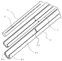
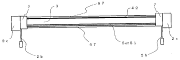
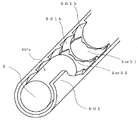
- FIG. 1 is a perspective view of a light source device according to Embodiment 1.
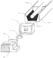
- FIG. 2 is an exploded perspective view of the light source device according to Embodiment 1.
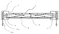
- FIG. 3 is a cross-sectional view showing an optical path in a major axis direction of the light source device according to Embodiment 1.
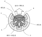
- FIG. 3 is a cross-sectional view showing an optical path orthogonal to the long axis direction of the light source device according to Embodiment 1.
- FIG. 10 is an exploded perspective view showing a light source device according to a modification of the first embodiment. It is sectional drawing which looked at the light source device which concerns on the modification of Embodiment 1 in the major axis direction of the light guide. It is a figure explaining the relationship between the thickness of fluorescent substance, and light emission luminance. It is a figure which shows the illumination light emission characteristic of the light source device which concerns on Embodiment 1. FIG. It is sectional drawing which looked at the light source device which concerns on Embodiment 2 of this invention in the direction orthogonal to the long axis of a light guide. 6 is a perspective view of a light source device according to Embodiment 2. FIG.
- FIG. 5 is a cross-sectional view showing the width of a reflection pattern of the light source device according to Embodiment 1 or 2.
- FIG. 6 is a cross-sectional view showing a reflection pattern at the position of a protrusion of the light source device according to Embodiment 1 or 2. It is sectional drawing which shows the reflection pattern of the intermediate position of a projection part.
- FIG. 10 is a cross-sectional view showing a phosphor layer at an intermediate position between protrusions of a light source device according to Embodiment 3. It is sectional drawing which shows the fluorescent substance layer of the position of the projection part in the different example of the light source device which concerns on Embodiment 3.
- FIG. It is sectional drawing of the intermediate position of the projection part in a different example. It is sectional drawing which shows the position of the projection part of the light source device which concerns on Embodiment 4 of this invention.
- FIG. 10 is a cross-sectional view showing a phosphor layer at an intermediate position between protrusions of a light source device according to Embodiment 3. It is sectional drawing which shows the fluorescent substance layer of the position of the projection part in the different example of the light source device which concerns on Embodiment 3.
- FIG. It is sectional drawing of the intermediate position of the projection part in a different example. It is sectional drawing which shows the position of the projection part of the light source device which concerns on Embodiment 4
- FIG. 10 is a cross-sectional view showing an intermediate position of a protrusion of a light source device according to Embodiment 4. It is sectional drawing which shows the position of the projection part of the light source device which concerns on Embodiment 5 of this invention.
- FIG. 10 is a cross-sectional view showing an intermediate position of a protrusion of a light source device according to Embodiment 5.
- FIG. 10 is a cross-sectional view showing the position of a protrusion of a light source device according to a modification of the fifth embodiment. It is sectional drawing which shows the intermediate position of the projection part of the light source device which concerns on a modification. It is sectional drawing which shows the position of the projection part of the light source device which concerns on Embodiment 6 of this invention.
- FIG. 10 is a cross-sectional view showing an intermediate position of a protrusion of a light source device according to a sixth embodiment.
- FIG. 10 is a cross-sectional view showing the position of a protrusion of a light source device according to a modification of the sixth embodiment. It is sectional drawing which shows the intermediate position of the projection part of the light source device which concerns on a modification. It is sectional drawing which shows the position of the projection part of the light source device which concerns on Embodiment 7 of this invention.
- FIG. 10 is a cross-sectional view showing an intermediate position of a protrusion of a light source device according to a seventh embodiment. It is sectional drawing which shows the position of the projection part of the light source device which concerns on the modification of Embodiment 7.
- FIG. 10 is a cross-sectional view showing an intermediate position of a protrusion of a light source device according to a seventh embodiment. It is sectional drawing which shows the position of the projection part of the light source device which concerns on the modification of Em
- FIG. 38 is an exploded perspective view of the vicinity of the holder of the light source device according to Embodiment 11. It is sectional drawing which looked at the light source device which concerns on Embodiment 11 in the major axis direction.
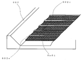
- FIG. 38 is a perspective view of a light guide body portion of a light source device according to Embodiment 12.
- FIG. 34 is a cross-sectional view of the vicinity of the holder of the light source device according to Embodiment 12.
- FIG. 20 is a detailed cross-sectional view of a case and a phosphor layer of a light source device according to Embodiment 12.
- FIG. 20 is a detailed cross-sectional view of a case and a phosphor layer of a light source device according to Embodiment 12.
- FIG. 20 is a detailed cross-sectional view of a case and a phosphor layer of a light source device according to Embodiment 12.
- FIG. 20 is a detailed cross-sectional view of a case and a phosphor layer of a light source device according to Embodiment 12. It is a detailed perspective view of the case and fluorescent substance layer of the light source device which concern on Embodiment 13 of this invention.
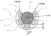
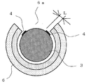
- FIG. 1 is a cross-sectional view of the light source device according to Embodiment 1 of the present invention viewed in a direction orthogonal to the long axis of the light guide.
- FIG. 2 is a perspective view of the light source device according to the first embodiment.
- the light source device includes an LED circuit 2, a light guide 3, a case 6 and a holder 7.
- the LED circuit 2 includes a light source 1, a substrate 2a, and a connector 2b.
- the light guide 3 is housed in the case 6. The ends of the light guide 3 and the case 6 are held by the holder 7.
- the light guide 3 has a columnar shape (rod shape) whose central axis is the longitudinal direction.
- the direction of the columnar central axis of the light guide 3 is referred to as the major axis direction (or the longitudinal direction), and the direction orthogonal to the major axis direction is referred to as the minor axis direction (or the lateral direction).
- the outer surface intersecting the central axis of the light guide 3 is referred to as an end surface, and the outer surface drawn by movement of a straight line (bus line) parallel to the central axis is referred to as a side surface or an outer peripheral surface.
- the case 6 surrounds the outer peripheral surface of the light guide 3 except for the strip-shaped opening 6 a formed along the long axis direction of the light guide 3.
- the light source 1 is disposed at the end of the light guide 3 so as to face the end face.
- the light source 1 is mounted on the substrate 2a.
- the LED circuit 2 is held by the holder 7 so that the light source 1 faces the end face of the light guide 3.
- the light source 1 is, for example, an LED (Light Emitting Diode).
- the light source 1 emits blue light having a wavelength of about 430 nm to 470 nm.
- a connector (external terminal) 2b is connected to the substrate 2a, and power is supplied to the light source 1 via the connector 2b.
- the substrate 2a is formed from, for example, a glass epoxy resin. You may equip the surface opposite to the surface where the light source 1 of the board
- the light guide 3 is a rod-shaped material made of a material having a refractive index (n) of 1.5 or more, such as transparent soda glass, transparent resin, or transparent sapphire having a transmittance of about 80%. Is mirror-finished.
- the light emitted from the light source 1 enters the light guide 3 from the end of the light guide 3.
- the light guide 3 guides light incident inside from the end along the longitudinal direction (long axis direction) of the light guide 3.
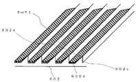
- FIG. 3 is an exploded perspective view of the light source device according to the first embodiment.
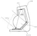
- FIG. 4 is a cross-sectional view of the light source device according to Embodiment 1 as viewed in the long axis direction of the light guide.
- a phosphor layer 5 is interposed between the outer peripheral surface of the light guide 3 and the surface of the case 6 surrounding the light guide 3.
- the light guided to the light guide 3 exits from the outer peripheral surface and is captured by the phosphor layer 5.
- the phosphor layer 5 emits fluorescence that is excited by absorbing part of the captured light.
- a part of the light captured by the phosphor layer 5 is reflected by the phosphor layer 5. Fluorescence and reflected light emitted from the phosphor layer 5 enter from the outer peripheral surface of the light guide 3.
- a part of the light guided to the light guide 3 and the fluorescence emitted from the phosphor layer 5 are emitted from the opening 6a of the case 6 to the outside.
- the light emitted from the opening 6a forms a band-like light beam having a wide width in the major axis direction, and irradiates the reading position of the document (irradiated body) (see FIG. 2).
- the path of light passing through the inside of the light guide 3 in the long axis direction is called a light guide path, and the path of light passing through the direction perpendicular to the long axis direction of the light guide 3 is called a cross path (transmission path).
- the crossing path (transmission path) can also be said to be a fluorescence emission path. Note that it can be said that the path through which light is guided to the emission region in the light source device according to the present embodiment is dominated by the transverse path (transmission path).
- the long axis direction corresponds to the main scanning direction of the image reading apparatus in which the light source device according to the present application is mounted
- the direction orthogonal to the long axis direction is the sub-scanning direction of the image reading apparatus. This corresponds to the scanning direction (conveying direction in which an object to be irradiated such as a document is conveyed).
- a white color in which a phosphor layer (phosphor) 5 is applied to the inner circumferential surface with a predetermined gap (d) of about 0.1 mm from the outer circumferential surface of the cylindrical light guide 3.
- the case 6 also referred to as a reflector, a case, or a bent reflector
- the outer peripheral surface of the light guide 3 and the inner peripheral surface of the case 6 are configured in a concentric shape with the same cross section perpendicular to the long axis direction.
- the central axes of the light guide 3 and the case 6 are parallel to the reading area (effective reading width).
- the case 6 is formed with an opening 6a serving as a take-out port (outgoing region) for emitting light to the irradiated body by forming a long groove having a constant width perpendicular to the long-axis direction along the long-axis direction. .
- a part of the light guide 3 is exposed from the opening 6a formed by a long groove along the long axis direction.
- a part of the light guide 3 may protrude from the opening 6a.
- An edge along the long axis direction of the opening 6a (corresponding to an end portion along the long axis direction of the case 6 or the case 6 and the phosphor layer 5) is referred to as a long groove end portion.
- a line-shaped light reflection pattern 4 is provided along the long axis direction on the outer peripheral surface of the light guide 3 facing the end of the long groove on both sides of the opening 6a with a predetermined gap.
- the line shape means that the light reflection pattern 4 is formed continuously in the major axis direction, including those in which the light reflection pattern 4 is not continuous along the major axis direction and the pattern pitch is changed.
- the light reflection pattern 4 is formed using, for example, a white light reflection member applied by silk printing or the like, or a lenticular lens or prism pattern formed in the light guide 3 by direct kerf.
- the light reflection patterns 4 are formed in two rows along the major axis direction in parallel with each other.
- the light reflection patterns 4 may be arranged in a line along the long axis direction.
- the light reflection pattern 4 is provided along the long axis direction on the outer peripheral surface of the light guide 3 at a position facing at least a part of the phosphor layer 5 via the inside of the light guide 3.
- the light reflection pattern 4 may protrude from the end of the long groove and partially or entirely on the opening 6a side (both in the long axis direction and the short axis direction).
- the opening 6a in the light source device (line light source) according to the present application including the first embodiment has been described as being formed at one place, the opening 6a along the long axis direction can be seen in the cross section of FIG. You may form in a location and may irradiate light (complex light mentioned later) in two directions.
- FIG. 3 a state where the notched portion is connected by the opening 6 a of the case 6 at the end portion in the long axis direction, that is, the opening is connected to a hole through which the light guide 3 formed on the end surface of the case 6 is passed.
- the openings 6a can be easily formed at two locations along the long axis direction.
- the phosphor layer 5 having a thickness (t) of about 50 ⁇ m is applied to the inner surface of the case 6 (the surface surrounding the outer peripheral surface of the light guide 3).
- a phosphor that emits red light having a wavelength of about 600 nm and a phosphor that emits green light having a wavelength of about 525 nm are mixed and applied to the phosphor layer 5.
- Blue light is captured by the phosphor layer 5, and part of the blue light is reflected by the phosphor layer 5, and is irradiated to the irradiated object through the opening 6 a across the inside of the light guide 3.
- the other blue light is absorbed by the phosphor layer 5 and emits excited fluorescence. That is, the phosphor layer 5 emits two types of composite light (color mixture light) converted into light having a wavelength different from that of blue light.
- the fluorescence emitted from the phosphor layer 5 crosses the inside of the light guide 3 and is irradiated to the irradiated body as composite light from the opening 6a. Therefore, the object to be irradiated is irradiated with pseudo white light in which blue light, red light, and green light are mixed.
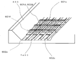
- the light guide 3 is fixed by protrusions 6b provided at both ends and the center of the case 6 as shown in FIG. It can be seen from FIG. 3 that when the phosphor layer 5 is in the form of a sheet, the protrusion 6 b can support the light guide 3 through the hole of the phosphor layer 5.
- the protrusion 6 b is inserted into the hole of the phosphor layer 5 so that the phosphor layer 5 is positioned by the protrusion 6 b, that is, the case 6. It can be carried out.
- the light source 1 placed on the substrate 2a of the LED circuit 2 is housed on one end side of the hollow portion of the holder 7 having the hollow portion, and the light guide 3 is incorporated on the other end side. It is configured by inserting the end of the case 6.
- the holder 7 is provided on both ends of the case 6, and the blue light emitted from the light source 1 is incident from both sides of the light guide 3.
- the holder 7 and the light source 1 may be disposed only on one end of the light guide 3.
- the relationship between the light source 1 and the holder 7 will be described.
- the substrate 2a on which the blue light source 1 provided at the end of the light guide 3 is mounted is fixed by a holder 7 as a holding mechanism.
- the LED circuit 2 is attached to the light guide 3 and the case 6 so that the optical position of the optical axis of the light source 1 and the center of the irradiation axis through which light passes at the end of the light guide 3 coincide.
- the light source 1 includes one or a plurality of blue LEDs.
- the holder 7 is configured to hold the light source 1 at a predetermined interval with respect to the end portion of the light guide 3 so that blue light emitted from the light source 1 is stably taken into the light guide 3.
- the holder 7 has, for example, a two-stage fitting insertion structure shown in FIG. 1 in order to prevent displacement of the light guide 3 and the case 6 and performs positioning at both ends of the light guide 3. Structured.
- the fitting of the holder 7 to the light guide 3 is, for example, a depth of 2 mm or more when the diameter of the light guide 3 is 4 mm, and the blue light incident from the light source 1 has a total reflection angle with respect to the surface of the light guide 3. Only light that is incident at a smaller angle than the light guide 3 is configured to enter the light guide 3. Outside the holder 7, the direct light from the light source 1 is not directly involved as illumination light. In addition, in the vicinity of the holder 7, in FIG.
- the notch-shaped portions are connected by the opening 6 a of the case 6 at the end in the long axis direction, and the openings 6 a along the long axis direction are formed at two locations. By doing so, the performance deterioration of the light source device can be prevented.
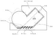
- FIG. 5 is a cross-sectional view showing the optical path in the major axis direction of the light source device according to Embodiment 1.
- FIG. 6 is a cross-sectional view showing an optical path perpendicular to the long axis direction of the light source device according to Embodiment 1.
- the light emitted from the light source 1 is guided from one end side to the other end side in a cylindrical (rod-like) light guide 3 formed of a transparent material.
- a cylindrical (rod-like) light guide 3 formed of a transparent material.
- the light is scattered or specularly reflected by the light reflection pattern 4 provided on the light guide 3, to the phosphor layer 5. Irradiated.
- the fluorescence emitted from the phosphor layer 5 and the blue light reflected by the phosphor layer 5 are mixed and emitted from the opening 6 a of the case 6 through the light guide 3.
- a composite light (mixed color light) of fluorescence and blue light is irradiated toward an irradiation object such as a document placed facing the opening 6a.
- the light guide 3 Since the light guide 3 has a higher refractive index than that of the external space, the light incident from the end of the light guide 3 is larger than the total reflection angle when reaching the surface of the mirror-shaped light guide 3. It is incident at an angle and propagates through the light guide in the light guide 3 by being totally reflected by the surface.
- the case 6 is not only used as a support member for the light guide 3 by the protrusions 6 b, but is also a phosphor layer provided between the surface surrounding the light guide 3 in the case 6 and the outer peripheral surface of the light guide 3. 5 also serves as a support member.
- the case 6 also serves as a support substrate (support member) for the phosphor layer 5 formed on the inner surface of the case 6 on the light guide 3 side of the case 6.
- the outer peripheral surface of the light guide 3 and the inner peripheral surface of the case 6 are held by a predetermined gap (gap). By making this gap constant, the stability of the position of the phosphor layer 5 with respect to the light guide 3 is ensured.
- the case 6 has a protrusion 6 b (a small contact area with the light guide 3 having a height of about 0.1 mm on the inner surface at three locations, both ends and the center.
- a support member for the light guide 3) is formed.
- a predetermined gap (d> t) is maintained between the phosphor layer 5 formed on the inner surface of the case 6 and the light guide 3 by closely contacting the protrusion 6 b and the light guide 3.
- the phosphor layer 5 is formed of a dye or pigment having a fluorescence wavelength such as red or green (yellowish green).
- the phosphor layer 5 is formed at least on the inner surface of the case 6 facing the light reflection pattern 4 of the light guide 3.
- the blue light irradiated from the light guide 3 to the phosphor layer 5 becomes a composite light of the fluorescence from the phosphor layer 5 and the diffuse reflected light of the blue light reflected by the surface of the phosphor layer 5.
- the composite light is radiated from the opening 6 a of the case 6 through the transverse path of the light guide 3. As a result, the composite light (pseudo white light) is irradiated to the irradiated object.
- the protrusions 6b of the case 6 are provided at both ends and the center of the case 6.
- protrusions 6b having a predetermined interval in the major axis direction are formed on the inner surface of the case 6. Since the light guide 3 is supported by the protrusion 6b, it is easy to hold the phosphor layer 5 and set the distance between the phosphor layer 5 and the light guide 3.
- a protrusion 6c having a ridge line along the long axis direction may be formed uniformly and continuously in the long axis direction.
- the shape of the cross section orthogonal to the long axis direction of the case 6 is the same over the long axis direction, the forming process of the case 6 is facilitated.
- FIG. 9 is a diagram for explaining the relationship between the thickness of the phosphor and the light emission luminance.
- the phosphor layer 5 has a thickness of, for example, about 50 ⁇ m.
- the conversion efficiency for generating fluorescence is improved, energy saving and phosphor layer are achieved. It is possible to prevent the emission intensity from becoming uneven due to the variation in the film thickness of No. 5.
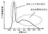
- FIG. 10 is a diagram showing illumination light emission characteristics of the light source device according to Embodiment 1.
- FIG. 10 the peak wavelength of about 450 nm and the composite light emitted from the phosphor ranging from about 500 to 630 nm are combined to give white light.
- the blue light reflected by the phosphor layer 5 and the composite light generated by the phosphor layer 5 are mixed and transmitted through the light guide 3.
- White illumination light is given to the irradiated object from the opening 6 a of the case 6. Since the light guide 3 has a cylindrical shape, the reflected light and the generated fluorescence reflected by the surface of the phosphor layer 5 are collected by the light guide 3 and are applied to the irradiated object by the lens effect. There is an effect of improving illumination illuminance.
- FIG. 11 is sectional drawing which looked at the light source device which concerns on Embodiment 2 of this invention in the direction orthogonal to the long axis of a light guide.
- 12A is a perspective view of a light source device according to Embodiment 2.
- FIG. 12B is a cross-sectional view of the light source device according to Embodiment 2 as viewed in the long axis direction of the light guide. 11 to 12B, the same reference numerals as those in FIGS. 1, 2, and 4 denote the same or corresponding parts.
- the light source 11 emits light having a wavelength of about 350 nm to 380 nm using, for example, an LED that emits ultraviolet rays.
- the LED circuit 2 includes a connector 2 b that mounts a light source 11 on a substrate 2 a such as an epoxy material and supplies power from the outside to the light source 11.
- the light guide 3 is formed by processing a member having a refractive index (n) of 1.5 or more into a rod shape, such as transparent soda glass, transparent resin, or transparent sapphire having a transmittance of about 80%. Is mirror-finished.
- the light of the light source 11 is incident from the end of the light guide 3 and the ultraviolet light (ultraviolet light) incident on the inside is guided along the longitudinal direction (long axis direction).
- a path of light passing through the inside of the light guide 3 in the long axis direction is called a light guide path, and a path of light passing through the direction orthogonal to the long axis direction of the light guide 3 is called a transverse path (transmission path). .
- the white case 6 in which the phosphor layer 51 is applied to the inner peripheral surface with a predetermined gap of about 0.1 mm from the outer peripheral surface of the columnar (rod-shaped) light guide 3. Is installed so as to surround the light guide 3.
- the case 6 is formed with an opening 6a serving as a take-out port (outgoing region) for emitting light to the irradiated body by forming a long groove having a constant width perpendicular to the long-axis direction along the long-axis direction. .
- a part of the light guide 3 is exposed from the opening 6a formed by a long groove along the long axis direction. A part of the light guide 3 may protrude from the opening 6a.
- a line-shaped light reflection pattern 4 is provided along the long axis direction on the outer peripheral surface of the light guide 3 facing the end of the long groove on both sides of the opening 6a with a predetermined gap.
- the line shape means that the light reflection pattern 4 is formed continuously in the major axis direction, including those in which the light reflection pattern 4 is not continuous along the major axis direction and the pattern pitch is changed.
- the light reflection pattern 4 is formed using, for example, a white light reflection member applied by silk printing or the like, or a lenticular lens or prism pattern formed in the light guide 3 by direct kerf.
- the light reflection patterns 4 are formed in two rows along the major axis direction in parallel with each other.
- the light reflection patterns 4 may be arranged in a line along the long axis direction.
- the light reflection pattern 4 is provided along the long axis direction on the outer peripheral surface of the light guide 3 at a position facing at least a part of the phosphor layer 51 via the inside of the light guide 3.
- the light reflection pattern 4 may protrude from the end of the long groove and partially or entirely on the opening 6a side (both in the long axis direction and the short axis direction).
- a phosphor layer 51 having a thickness (t) of about 50 ⁇ m is applied to the inner surface of the case 6 (the surface surrounding the outer peripheral surface of the light guide 3).
- a phosphor that emits red light having a wavelength of approximately 600 nm, a phosphor that emits green light having a wavelength of approximately 525 nm, and a phosphor that emits blue light having a wavelength of approximately 450 nm are coated on the phosphor layer 51.
- Blue light is captured by the phosphor layer 51, and a part of the ultraviolet light is reflected by the phosphor layer 51, crosses the inside of the light guide 3 and is irradiated to the irradiated object from the opening 6 a.
- the other ultraviolet light is absorbed by the phosphor layer 51 and emits excited fluorescence. That is, the phosphor layer 51 emits three types of composite light (color mixture light) converted into light having a wavelength different from that of ultraviolet light.
- the fluorescence emitted from the phosphor layer 51 crosses the inside of the light guide 3 and is irradiated to the irradiated body as composite light from the opening 6a. Therefore, the object to be irradiated is irradiated with pseudo white light in which blue light, red light, and green light are mixed.
- the light source 11 placed on the substrate 2a of the LED circuit 2 is housed in one end side of the hollow portion of the holder 7 having the hollow portion, and the light guide 3 is incorporated in the other end side. It is configured by inserting the end of the case 6.
- the holder 7 is provided on both ends of the case 6, and the ultraviolet light emitted from the light source 11 is incident from both sides of the light guide 3.
- the holder 7 and the light source 11 may be disposed only on one end of the light guide 3.
- the relationship between the light source 1 and the holder 7 and the operation of the light source device are the same as those in the first embodiment.
- an ultraviolet light shielding part that shields ultraviolet light emitted from the opening 6a is formed so that the irradiated object is not irradiated with ultraviolet light.
- an ultraviolet light shielding pattern 8 (ultraviolet light cut pattern, ultraviolet light cut filter) formed in the opening 6a portion of the light guide 3 is taken as an example of the ultraviolet light shielding portion.
- the ultraviolet light emitted from the opening 6a of the case 6 along the long axis direction is shielded on the outer peripheral surface of the light guide 3 sandwiched between the two rows of light reflection patterns 4.
- An ultraviolet light shielding pattern (ultraviolet cut filter) 8 is provided.
- the ultraviolet light shielding pattern (ultraviolet cut filter) 8 is sandwiched between the two long groove ends. Formed in part.
- FIG. 13 is a diagram showing the characteristics of the ultraviolet cut filter of the light source device according to the second embodiment.
- the ultraviolet cut filter 8 has a cutoff wavelength in the vicinity of about 430 nm, does not transmit light having a wavelength shorter than 430 nm, and transmits light having a wavelength longer than 430 nm including blue light.
- a filter material that cuts ultraviolet rays is applied to the light guide 3 or vapor-deposited.
- an ultraviolet light shielding pattern (ultraviolet cut filter) 8 that is an ultraviolet light shielding portion may be formed in the light source device.
- an ultraviolet light shielding pattern (ultraviolet cut filter) 8 that is an ultraviolet light shielding portion may be formed in the light source device.
- the fluorescent visible light transmitted through the ultraviolet cut filter 8 is irradiated to the irradiated object.
- the light source device according to Embodiment 2 can be illumination having a flat emission spectrum in the visible light region.
- the ultraviolet light emitted from the light guide 3 to the opening 6 a is shielded by the ultraviolet cut filter 8.
- the composite light generated by the phosphor layer 51 passes through the inside of the light guide 3 and gives white illumination light to the irradiated body from the opening 6a of the case 6.
- the fluorescence generated by the phosphor layer 5 is collected by the light guide 3 and the lens effect causes the light to be irradiated. There is also an effect of improving illumination illuminance.
- FIG. 14A is a cross-sectional view showing the width of the reflection pattern of the light source device according to Embodiment 1 or 2.
- FIG. 14B is a cross-sectional view showing an example in which the width of the reflection pattern is different.
- the position of the light reflection pattern 4 is provided on the outer peripheral surface of the light guide 3 that faces each end of the opening 6a formed by a long groove with a gap. .
- the light reflecting pattern 4 may protrude from the end of the long groove and partially or entirely on the opening 6a side (both in the long axis direction and the short axis direction).
- FIGS. 15A and 15B An example in which a part of the light reflection pattern 4 protrudes into the opening 6a is shown in FIGS. 15A and 15B.
- FIG. 15A is a cross-sectional view showing a reflection pattern of the position of the protrusion of the light source device according to Embodiment 1 or 2.
- FIGS. 15A and 15B are cross-sectional views showing a reflection pattern at an intermediate position of the protrusion. As shown in FIGS. 15A and 15B, even if a part of the light reflection pattern 4 enters the opening 6a side, the same effects as those described in the first and second embodiments are obtained.
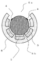
- FIG. 16A is a cross-sectional view showing the phosphor layer at the position of the protrusion of the light source device according to Embodiment 3 of the present invention.
- FIG. 16B is a cross-sectional view showing the phosphor layer at an intermediate position of the protrusion of the light source device according to Embodiment 3.
- phosphor layers 5 are provided on a plurality of lines along the major axis direction in which the width in the direction orthogonal to the major axis direction is constant.
- the phosphor layer 5 (phosphor layer 51) is provided over the entire inner surface of the case 6, whereas in the third embodiment, the phosphor layer 5 is formed in a stripe shape. A slit portion is provided between adjacent phosphor layers 5 (phosphor layer 51). Further, at least the inner surface region of the case 6 where the phosphor layer 5 (phosphor layer 51) is not applied (formed) is formed of a light absorbing material such as black so that light is not reflected. Blue light is absorbed by the inner surface of the case 6, and the luminance of the blue light component shown in FIG. 10 can be reduced to approach the luminance of the phosphor layer light emitting component.
- the luminance of the white emission spectrum can be adjusted by applying a black plastic resin to the case (reflector) 6.
- the light source device according to the third embodiment can be implemented even when the inner surface area of the case 6 is not black but white.
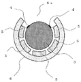
- FIG. 17A is a cross-sectional view showing a phosphor layer at the position of a protrusion in a different example of the light source device according to Embodiment 3.
- FIG. 17B is a cross-sectional view of an intermediate position between the protrusions in different examples.
- the phosphor layer is applied to the entire inner surface of the case 6, but the application region of the phosphor layer 5 may not be the entire inner surface of the case 6 as shown in FIG. 17.
- the phosphor layer 5 having a width of 2 mm and about 3 lines is provided around the area of the case 6 facing the opening 6a.
- the luminance of the blue light component can be reduced by using the black case 6.
- the light source device according to the third embodiment can be implemented even when the inner surface area of the case 6 is not black but white.
- FIG. 18A is a cross-sectional view showing the position of the protrusion of the light source device according to Embodiment 4 of the present invention.
- FIG. 18B is a cross-sectional view illustrating an intermediate position of the protrusion of the light source device according to Embodiment 4.
- a light guide 31 having an elliptical cross section orthogonal to the long axis is used.
- the outline of the cross section orthogonal to the long axis of the case 61 is an ellipse.
- a white case 61 in which a phosphor is applied to the inner peripheral surface with a predetermined gap of about 0.1 mm from the outer peripheral surface of the rod-shaped light guide 31 whose section perpendicular to the major axis is elliptical is introduced. It arrange
- Other configurations are the same as those in the first embodiment.
- the case 61 is formed with an opening 61a serving as a take-out port (outgoing region) for emitting light to the irradiated body by forming a long groove having a constant width perpendicular to the long-axis direction along the long-axis direction. .
- the case 61 surrounds the outer peripheral surface of the light guide 31 except for the strip-shaped opening 61 a formed along the long axis direction of the light guide 31.
- a part of the light guide 31 is exposed from the opening 61a formed by a long groove along the long axis direction.
- a part of the light guide 31 may protrude from the opening 61a.
- An edge along the long axis direction of the opening 61a (corresponding to the case 61 or an end portion along the long axis direction of the case 61 and the phosphor layer 5) is referred to as a long groove end portion.
- a linear light reflection pattern 4 is provided along the long axis direction on the outer peripheral surface of the light guide 31 facing the end of the long groove on both sides of the opening 61a with a predetermined gap.
- the line shape means that the light reflection pattern 4 is formed continuously in the major axis direction, including those in which the light reflection pattern 4 is not continuous along the major axis direction and the pattern pitch is changed.
- the light reflection pattern 4 is formed using, for example, a white light reflection member applied by silk printing or the like, or a lenticular lens or a prism pattern formed in the light guide 31 directly by a kerf.
- the light reflection patterns 4 are formed in two rows along the major axis direction in parallel with each other.
- the light reflection patterns 4 may be arranged in a line along the long axis direction.
- the light reflection pattern 4 is provided along the long axis direction on the outer peripheral surface of the light guide 31 at a position facing at least a part of the phosphor layer 5 via the inside of the light guide 31.
- a part of the blue light passing through the light guide path of the light guide 31 is scattered or specularly reflected by the light reflection pattern 4 and transmitted through the transverse path inside the light guide 31, and the light reflection pattern 4 of the light guide 31. And is captured by the phosphor layer 5 of the case 61.
- the light reflection pattern 4 may protrude from the end of the long groove and partially or entirely on the opening 6a side (both in the long axis direction and the short axis direction).
- the phosphor layer 5 having a thickness of about 50 ⁇ m is applied to the inner surface of the case 61 (the surface surrounding the outer peripheral surface of the light guide 31).
- a phosphor that emits red light having a wavelength of about 600 nm and a phosphor that emits green light having a wavelength of about 525 nm are mixed and applied to the phosphor layer 5.
- Blue light is captured by the phosphor layer 5, and part of the blue light is reflected by the phosphor layer 5, and is irradiated to the irradiated object from the opening 61 a across the inside of the light guide 31.
- the other blue light is absorbed by the phosphor layer 5 and emits excited fluorescence. That is, the phosphor layer 5 emits two types of composite light (color mixture light) converted into light having a wavelength different from that of blue light.
- the fluorescence emitted from the phosphor layer 5 crosses the inside of the light guide 31 and is irradiated to the irradiated body as composite light from the opening 61a. Therefore, the object to be irradiated is irradiated with pseudo white light in which blue light, red light, and green light are mixed.
- the relationship between the light source 1 and the holder 7 and the operation of the light source device are the same as those in the first embodiment.
- the blue light reflected by the phosphor layer 5 and the composite light generated by the phosphor layer 5 are mixed and transmitted through the light guide 31.
- White illumination light is given to the irradiated object from the opening 61 a of the case 61. Since the light guide 31 has an elliptical cross-sectional shape, the reflected light reflected by the surface of the phosphor layer 5 and the generated fluorescence are collected by the light guide 31, and the illumination effect on the irradiated object is reduced by the lens effect. There is an effect of improving. Moreover, there exists an advantage which can mount many LED facing an elliptical end surface.
- the light source 1 and the phosphor layer 5 are replaced with the light source 11 and the phosphor layer 51, and the ultraviolet light shielding pattern 8 is formed on the light guide 31.
- a form using ultraviolet light may be used.
- the ultraviolet light reaching the opening 61a is shielded by the ultraviolet light shielding pattern 8, and the composite light generated by the phosphor layer 51 passes through the inside of the light guide 31 and passes through the opening 61a of the case 61 to the irradiated body.
- the phosphor layer 51 generates three types of composite light (color mixture light) converted into light having a wavelength different from that of ultraviolet light.
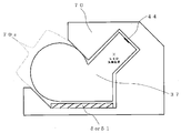
- FIG. FIG. 19A is a cross-sectional view showing the position of the protrusion of the light source device according to Embodiment 5 of the present invention.
- FIG. 19B is a cross-sectional view showing an intermediate position of the protrusion of the light source device according to Embodiment 5.
- the light guide 32 is used in which the cross section orthogonal to the long axis has a shape in which a notch 62c is formed in a part of an ellipse.
- the light reflection patterns 4 along the long axis direction are provided on both sides in contact with the side along the long axis direction of the notch 62c of the light guide 32.
- Other configurations are the same as those in the first embodiment.
- the case 62 is formed with an opening 62a serving as a takeout port (outgoing region) for emitting light to the irradiated body by forming a long groove having a constant width perpendicular to the long axis direction along the long axis direction. .
- the case 62 surrounds the outer peripheral surface of the light guide 32 except for a band-shaped opening 62a formed along the long axis direction.
- a part of the light guide 32 is exposed from the opening 62a formed by a long groove along the long axis direction.
- a part of the light guide 32 may protrude from the opening 62a.
- An edge along the long axis direction of the opening 62a (corresponding to the case 62 or the end portion along the long axis direction of the case 62 and the phosphor layer 5) is referred to as a long groove end portion.
- a linear light reflection pattern 4 is provided along the long axis direction on the outer peripheral surface of the light guide 32 facing the end of the long groove on both sides of the opening 62a with a predetermined gap.
- the line shape means that the light reflection pattern 4 is formed continuously in the major axis direction, including those in which the light reflection pattern 4 is not continuous along the major axis direction and the pattern pitch is changed.
- the light reflection pattern 4 is formed by using, for example, a white light reflection member applied by silk printing or the like, or a lenticular lens or prism pattern formed directly on the light guide 32 by kerfs.
- the light reflection patterns 4 are formed in two rows along the major axis direction in parallel with each other.
- the light reflection patterns 4 may be arranged in a line along the long axis direction.
- the light reflection pattern 4 is provided along the long axis direction on the outer peripheral surface of the light guide 32 at a position facing at least a part of the phosphor layer 5 via the inside of the light guide 32.
- the light reflection pattern 4 may protrude from the end of the long groove and part or all of it may protrude toward the opening 62a (both in the long axis direction and the short axis direction).
- the phosphor layer 5 having a thickness of about 50 ⁇ m is applied to the inner surface of the case 62 (the surface surrounding the outer peripheral surface of the light guide 32).
- a phosphor that emits red light having a wavelength of about 600 nm and a phosphor that emits green light having a wavelength of about 525 nm are mixed and applied to the phosphor layer 5.
- Blue light is captured by the phosphor layer 5, a part of the blue light is reflected by the phosphor layer 5, and is irradiated to the irradiated object from the opening 62 a across the inside of the light guide 32.
- the other blue light is absorbed by the phosphor layer 5 and emits excited fluorescence. That is, the phosphor layer 5 emits two types of composite light (color mixture light) converted into light having a wavelength different from that of blue light.
- the fluorescence emitted from the phosphor layer 5 crosses the inside of the light guide 32 and is irradiated to the irradiated object as composite light from the opening 62a. Therefore, the object to be irradiated is irradiated with pseudo white light in which blue light, red light, and green light are mixed.
- the relationship between the light source 1 and the holder 7 and the operation of the light source device are the same as those in the first embodiment.
- the blue light reflected by the phosphor layer 5 and the composite light generated by the phosphor layer 5 are mixed and transmitted through the light guide 32.
- White illumination light is given to the irradiated object from the opening 62a of the case 62. Since the light guide 32 has an elliptical cross-sectional shape, the reflected light reflected by the surface of the phosphor layer 5 and the generated fluorescence are collected by the light guide 32, and the illumination effect on the irradiated object is increased by the lens effect. There is an effect of improving. Moreover, there exists an advantage which can mount many LED facing an elliptical end surface.
- FIG. 20A is a cross-sectional view showing the position of the protrusion of the light source device according to the modification of the fifth embodiment.
- FIG. 20B is a cross-sectional view illustrating an intermediate position of the protrusion of the light source device according to the modification.
- the light reflection pattern 41 is added to the outer peripheral surface of the light guide 32 that faces the light reflection pattern 4 disposed on the opening 62a side of the light guide 32, thereby exiting from the opening 62a.
- the amount of blue light irradiated can be increased.
- the amount of blue light emitted can be adjusted by changing the installation position of the light reflection pattern 41 installed on the outer peripheral surface of the light guide 32.
- the light reflection pattern 41 is provided in a line along the long axis direction on the outer peripheral surface of the light guide 32 at a position facing at least a part of the phosphor layer 5 via the inside of the light guide 32. .
- the light source 1 and the phosphor layer 5 are replaced with the light source 11 and the phosphor layer 51, and the ultraviolet light shielding pattern 8 is formed on the light guide 32.
- a form using ultraviolet light may be used.
- the ultraviolet light reaching the opening 62a is shielded by the ultraviolet light shielding pattern 8, and the composite light generated by the phosphor layer 51 passes through the inside of the light guide 32 and passes through the opening 62a of the case 62 to the irradiated body.
- the phosphor layer 51 generates three types of composite light (color mixture light) converted into light having a wavelength different from that of ultraviolet light.
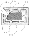
- FIG. 21A is a cross-sectional view showing the position of the protrusion of the light source device according to Embodiment 6 of the present invention.
- FIG. 21B is a cross-sectional view showing an intermediate position of the protrusion of the light source device according to Embodiment 6.
- the light guide 33 is used in which a cross section orthogonal to the long axis has a shape (pentagon) in which a notch 63c is formed in a part of a quadrangle.
- the light reflection patterns 4 along the long axis direction are provided on both sides in contact with the side along the long axis direction of the notch 63c of the light guide 33.
- Other configurations are the same as those in the first embodiment.
- the case 63 is formed with an opening 63a serving as a take-out port (outgoing region) for emitting light to the irradiated body by forming a long groove having a constant width orthogonal to the long-axis direction along the long-axis direction. .
- the case 63 surrounds the outer peripheral surface of the light guide 33 except for the strip-shaped opening 63a formed along the long axis direction.
- a part of the light guide 33 is exposed from the opening 63a formed by a long groove along the long axis direction.
- a part of the light guide 33 may protrude from the opening 63a.
- An edge along the long axis direction of the opening 63a (corresponding to the case 63 or an end portion along the long axis direction of the case 63 and the phosphor layer 5) is referred to as a long groove end portion.
- a linear light reflection pattern 4 is provided along the long axis direction on the outer peripheral surface of the light guide 33 facing the end of the long groove on both sides of the opening 63a with a predetermined gap.
- the line shape means that the light reflection pattern 4 is formed continuously in the major axis direction, including those in which the light reflection pattern 4 is not continuous along the major axis direction and the pattern pitch is changed.
- the light reflection pattern 4 is formed using, for example, a white light reflection member applied by silk printing or the like, or a lenticular lens or a prism pattern formed in the light guide 33 directly by a kerf.
- the light reflection patterns 4 are formed in two rows along the major axis direction in parallel with each other.
- the light reflection patterns 4 may be arranged in a line along the long axis direction.
- the light reflection pattern 4 is provided along the long axis direction on the outer peripheral surface of the light guide 33 at a position facing at least a part of the phosphor layer 5 via the inside of the light guide 33.
- a part of the blue light passing through the light guide path of the light guide 33 is scattered or specularly reflected by the light reflection pattern 4 and transmitted through the transverse path inside the light guide 33, and the light reflection pattern 4 of the light guide 33. And is captured by the phosphor layer 5 of the case 63.
- the light reflection pattern 4 may protrude from the end of the long groove and may partly or entirely protrude toward the opening 63a (both in the long axis direction and the short axis direction).
- the phosphor layer 5 having a thickness of about 50 ⁇ m is applied to the inner surface of the case 63 (the surface surrounding the outer peripheral surface of the light guide 33).
- a phosphor that emits red light having a wavelength of about 600 nm and a phosphor that emits green light having a wavelength of about 525 nm are mixed and applied to the phosphor layer 5.
- Blue light is captured by the phosphor layer 5, and part of the blue light is reflected by the phosphor layer 5, and is irradiated to the irradiated object through the opening 63 a across the inside of the light guide 33.
- the other blue light is absorbed by the phosphor layer 5 and emits excited fluorescence. That is, the phosphor layer 5 emits two types of composite light (color mixture light) converted into light having a wavelength different from that of blue light.
- the fluorescence emitted from the phosphor layer 5 crosses the inside of the light guide 33 and is irradiated to the irradiated body as composite light from the opening 63a. Therefore, the object to be irradiated is irradiated with pseudo white light in which blue light, red light, and green light are mixed.
- the relationship between the light source 1 and the holder 7 and the operation of the light source device are the same as those in the first embodiment.
- the blue light reflected by the phosphor layer 5 and the composite light generated by the phosphor layer 5 are mixed and transmitted through the light guide 33.
- White illumination light is given to the irradiated object from the opening 63a of the case 63.
- the notch 63c of the light guide 33 serves as a light exit surface.
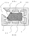
- FIG. 22A is a cross-sectional view showing the position of the protrusion of the light source device according to the modification of the sixth embodiment.
- FIG. 22B is a cross-sectional view illustrating an intermediate position of the protrusion of the light source device according to the modification.
- the light reflection pattern 41 is added to the outer peripheral surface of the light guide 33 facing the light reflection pattern 4 provided on the opening 63a side of the light guide 33, thereby emitting light from the opening 63a.
- the amount of blue light irradiated can be increased.
- the amount of blue light emitted can be adjusted by changing the installation position of the light reflection pattern 41 installed on the outer peripheral surface of the light guide 33.
- the light reflection pattern 41 is provided in a line along the long axis direction on the outer peripheral surface of the light guide 33 at a position facing at least a part of the phosphor layer 5 via the inside of the light guide 33. .
- the light source 1 and the phosphor layer 5 are replaced with the light source 11 and the phosphor layer 51, and the ultraviolet light shielding pattern 8 is formed on the light guide 33.
- a form using ultraviolet light may be used.
- the ultraviolet light reaching the opening 63a is shielded by the ultraviolet light shielding pattern 8, and the composite light generated by the phosphor layer 51 passes through the inside of the light guide 33 and passes through the opening 63a of the case 63 to the irradiated body.
- the phosphor layer 51 generates three types of composite light (color mixture light) converted into light having a wavelength different from that of ultraviolet light.
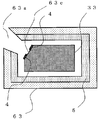
- FIG. 23A is a cross-sectional view showing the position of the protrusion of the light source device according to Embodiment 7 of the present invention.
- FIG. 23B is a cross-sectional view showing an intermediate position of the protrusion of the light source device according to Embodiment 7.
- the notch 63c is formed in the light guide 33 as in the sixth embodiment, but the light reflection pattern 4 is provided on the surface of the light guide 33 other than the notch 63c.
- the light reflection pattern 4 along the long axis direction is provided outside the notch portion 63 c in contact with the side along the long axis direction of the notch portion 63 c of the light guide 33.
- the case 63 is formed with an opening 63a serving as a take-out port (outgoing region) for emitting light to the irradiated body by forming a long groove having a constant width orthogonal to the long-axis direction along the long-axis direction. .
- the case 63 surrounds the outer peripheral surface of the light guide 33 except for the strip-shaped opening 63a formed along the long axis direction.
- a part of the light guide 33 is exposed from the opening 63a formed by a long groove along the long axis direction.
- a part of the light guide 33 may protrude from the opening 63a.
- An edge along the long axis direction of the opening 63a is referred to as a long groove end.
- the side of the light guide 33 adjacent to the notch 63c on the outer peripheral surface of the light guide 33 facing the long groove ends on both sides of the opening 63a is adjacent to the notch 63c and in the long axis direction.
- a line-shaped light reflection pattern 4 is provided along the line.
- the line shape means that the light reflection pattern 4 is formed continuously in the major axis direction, including those in which the light reflection pattern 4 is not continuous along the major axis direction and the pattern pitch is changed.
- the light reflection pattern 4 is formed using, for example, a white light reflection member applied by silk printing or the like, or a lenticular lens or a prism pattern formed in the light guide 33 directly by a kerf.
- the light reflection patterns 4 are formed in two rows along the major axis direction in parallel with each other.
- the light reflection patterns 4 may be arranged in a line along the long axis direction.
- the light reflection pattern 4 is provided along the long axis direction on the outer peripheral surface of the light guide 33 at a position facing at least a part of the phosphor layer 5 via the inside of the light guide 33.
- a part of the blue light passing through the light guide path of the light guide 33 is scattered or specularly reflected by the light reflection pattern 4 and transmitted through the transverse path inside the light guide 33, and the light reflection pattern 4 of the light guide 33. And is captured by the phosphor layer 5 of the case 63.
- the light reflection pattern 4 may protrude from the end of the long groove and may partly or entirely protrude toward the opening 63a (both in the long axis direction and the short axis direction).
- the phosphor layer 5 having a thickness of about 50 ⁇ m is applied to the inner surface of the case 63 (the surface surrounding the outer peripheral surface of the light guide 33).
- a phosphor that emits red light having a wavelength of about 600 nm and a phosphor that emits green light having a wavelength of about 525 nm are mixed and applied to the phosphor layer 5.
- Blue light is captured by the phosphor layer 5, and part of the blue light is reflected by the phosphor layer 5, and is irradiated to the irradiated object through the opening 63 a across the inside of the light guide 33.
- the other blue light is absorbed by the phosphor layer 5 and emits excited fluorescence. That is, the phosphor layer 5 emits two types of composite light (color mixture light) converted into light having a wavelength different from that of blue light.
- the fluorescence emitted from the phosphor layer 5 crosses the inside of the light guide 33 and is irradiated to the irradiated body as composite light from the opening 63a. Therefore, the object to be irradiated is irradiated with pseudo white light in which blue light, red light, and green light are mixed.
- the relationship between the light source 1 and the holder 7 and the operation of the light source device are the same as those in the first embodiment.
- the blue light reflected by the phosphor layer 5 and the composite light generated by the phosphor layer 5 are mixed and transmitted through the light guide 33.
- White illumination light is given to the irradiated object from the opening 63a of the case 63.
- the notch 63c of the light guide 33 serves as a light exit surface. Blue light transmitted from the light reflection pattern 4 and leaking to the opening 63a can be reduced, and the area of the light emission region emitted from the notch 63c of the light guide 33 can be increased.
- FIG. 24A is a cross-sectional view illustrating the position of the protrusion of the light source device according to the modification of the seventh embodiment.
- FIG. 24B is a cross-sectional view showing an intermediate position of the protrusion of the light source device according to the modification.
- the light reflection pattern 41 is added to the outer peripheral surface of the light guide 33 that faces the light reflection pattern 4 disposed on the opening 63a side of the light guide 33, thereby exiting from the opening 63a.
- the amount of blue light irradiated can be increased.
- the amount of blue light emitted can be adjusted by changing the installation position of the light reflection pattern 41 installed on the outer peripheral surface of the light guide 33.
- the light reflection pattern 41 is provided in a line along the long axis direction on the outer peripheral surface of the light guide 33 at a position facing at least a part of the phosphor layer 5 via the inside of the light guide 33. .
- the light source 1 and the phosphor layer 5 are replaced with the light source 11 and the phosphor layer 51, and the ultraviolet light shielding pattern 8 is formed on the light guide 33.
- a form using ultraviolet light may be used.
- the ultraviolet light reaching the opening 63a is shielded by the ultraviolet light shielding pattern 8, and the composite light generated by the phosphor layer 51 passes through the inside of the light guide 33 and passes through the opening 63a of the case 63 to the irradiated body.
- the phosphor layer 51 generates three types of composite light (color mixture light) converted into light having a wavelength different from that of ultraviolet light.
- FIG. 25 is a cross-sectional view of the vicinity of the central portion of the light source device according to Embodiment 8 of the present invention.
- FIG. 26 is a cross-sectional view of the light source device according to Embodiment 8 as seen in the direction orthogonal to the long axis.
- the light guide body 34 similarly to the sixth and seventh embodiments, has a cross section in which a cutout portion 64c is formed at one vertex of a quadrangular shape, but the cutout portion 64c is formed from the cutout portion 63c. The width is narrow, so to speak, it is formed by chamfering.
- the light source device according to Embodiment 8 illustrates the case where the protrusions 64b are continuously formed in the long axis direction.
- the light reflection pattern 4 along the long axis direction is provided outside the cutout portion 64c in contact with the side along the long axis direction of the cutout portion 64c of the light guide 34.
- the case 64 is formed with an opening 64a serving as a take-out port (outgoing region) for emitting light to the irradiated body by forming a long groove having a constant width perpendicular to the long-axis direction along the long-axis direction. .
- the case 64 surrounds the outer peripheral surface of the light guide 34 except for the strip-shaped opening 64a formed along the long axis direction.
- a part of the light guide 34 is exposed from the opening 64a formed by a long groove along the long axis direction.
- a part of the light guide 34 may protrude from the opening 64a.
- An edge along the long axis direction of the opening 64a is referred to as a long groove end.
- the side of the light guide 34 adjacent to the notch 64c on the outer peripheral surface of the light guide 34 facing the long groove ends on both sides of the opening 64a is adjacent to the notch 64c and in the long axis direction.
- a line-shaped light reflection pattern 4 is provided along the line.
- the line shape means that the light reflection pattern 4 is formed continuously in the major axis direction, including those in which the light reflection pattern 4 is not continuous along the major axis direction and the pattern pitch is changed.
- the light reflection pattern 4 is formed by using, for example, a white light reflection member applied by silk printing or the like, or a lenticular lens or prism pattern formed directly on the light guide 34 by kerfs.
- the light reflection patterns 4 are formed in two rows along the major axis direction in parallel with each other.
- the light reflection patterns 4 may be arranged in a line along the long axis direction.
- the light reflection pattern 4 is provided along the long axis direction on the outer peripheral surface of the light guide 34 at a position facing at least a part of the phosphor layer 5 via the inside of the light guide 34.
- a part of the blue light passing through the light guide path of the light guide 34 is scattered or specularly reflected by the light reflection pattern 4 and transmitted through the transverse path inside the light guide 34, and the light reflection pattern 4 of the light guide 34. And is captured by the phosphor layer 5 of the case 64.
- the light reflection pattern 4 may protrude from the end of the long groove and part or all of it may protrude toward the opening 64a (both in the long axis direction and the short axis direction).
- the phosphor layer 5 having a thickness of, for example, about 50 ⁇ m is applied to the inner surface of the case 64 (the surface surrounding the outer peripheral surface of the light guide 34).
- a phosphor that emits red light having a wavelength of about 600 nm and a phosphor that emits green light having a wavelength of about 525 nm are mixed and applied to the phosphor layer 5.
- Blue light is captured by the phosphor layer 5, and part of the blue light is reflected by the phosphor layer 5, and is irradiated to the irradiated object through the opening 64 a across the inside of the light guide 34.
- the other blue light is absorbed by the phosphor layer 5 and emits excited fluorescence. That is, the phosphor layer 5 emits two types of composite light (color mixture light) converted into light having a wavelength different from that of blue light.
- the relationship between the light source 1 and the holder 7 and the operation of the light source device are the same as those in the first embodiment.
- the blue light reflected by the phosphor layer 5 and the composite light generated by the phosphor layer 5 are mixed and transmitted through the light guide 34.
- White illumination light is given to the irradiated object from the opening 64 a of the case 64.
- the chamfered cutout portion 64c of the light guide 34 serves as a light exit surface.
- a long axis is provided on the outer peripheral surface of the light guide 34 at a position facing at least a part of the phosphor layer 5 via the inside of the light guide 34 as in the sixth or seventh embodiment.
- the light reflection pattern 41 may be provided in a line along the direction.
- the configuration using the light source 1 that mainly emits blue light has been described.
- the configuration using the light source 11 that emits ultraviolet light described in the second embodiment Even if it exists, it is the same about the relationship between the light source 11 and the holder 7, and the effect
- the light source 1 and the phosphor layer 5 are replaced with the light source 11 and the phosphor layer 51, and the ultraviolet light shielding pattern 8 is formed on the light guide 34.
- a form using ultraviolet light may be used.
- the ultraviolet light reaching the opening 64a is shielded by the ultraviolet light shielding pattern 8, and the composite light generated by the phosphor layer 51 passes through the inside of the light guide 34 and passes through the opening 64a of the case 64 to the irradiated body.
- the phosphor layer 51 generates three types of composite light (color mixture light) converted into light having a wavelength different from that of ultraviolet light.
- the phosphor layers 5 and 51 are described as a mixture of phosphor materials. However, the phosphor layers 5 and 51 are separately formed, and each phosphor layer 5 and 51 emits monochromatic light. You may let them.
- the phosphor materials have mainly been described for red light emission, green light emission, and blue light emission. However, the present invention is not limited to these emission colors, and a light source device may be configured using a phosphor material such as orange light emission or yellow-green light emission. Good.
- Embodiment 9 FIG.
- the phosphor layer 5 or the phosphor layer 51 includes the surface of the cases 6, 61 to 64 surrounding the light guides 3, 31 to 34, the light guide 3, The case of interposing between the outer peripheral surfaces 31 to 34 has been described.
- phosphor layer 5 or phosphor layer 51 surrounds light guides 3 and 31 to 34 in cases 6 and 61 to 64 covering rod-like light guides 3 and 31 to 34. It is formed on the surface opposite to the side surface.
- FIG. 27 is an exploded perspective view of the vicinity of the holder of the light source device according to Embodiment 9 of the present invention.
- FIG. 28A is a cross-sectional view of the light guide portion of the light source device according to Embodiment 9.
- the cylindrical light guide 3 will be described as an example. Needless to say, the light guides 31 to 34 may have elliptical or polygonal cross sections.
- the transparent case 65 surrounds the outer peripheral surface of the light guide 3.
- the phosphor layer 5 is formed on a surface opposite to the surface surrounding the light guide 3 in the transparent case 65. That is, the phosphor layer 5 is formed on the outer peripheral surface of the transparent case 65.
- the phosphor layer 5 is separated by the light guide 3 and the transparent case 65, but surrounds the outer peripheral surface of the light guide 3 except for the opening 65a continuous along the long axis direction, and guides light from the opening 65a. A part of the body 3 is exposed or protruded.
- the opening 65a is an opening that surrounds the light guide 3 by the above-described phosphor layer 5 (phosphor layer 51) and is configured by a long groove along the long axis direction.
- the opening 65 a formed by the phosphor layer 5 (phosphor layer 51) may be narrowed by the arrangement of the light reflection pattern 4 formed on the light guide 3.
- the portion facing the opening 65a of the transparent case 65 may be an opening (opening) configured by a long groove along the long axis direction. That is, the transparent case 65 may have a shape similar to that of the case 6 (61 to 64), or may have a cylindrical shape having a hollow portion for housing the light guide 3 as illustrated.
- the shape of the protrusion 65b may be provided at both ends and the center of the case as in the protrusion 6b of FIG. 3, or as shown in FIGS. 7 and 8, uniformly in the long axis direction. It may be provided.
- the protruding portions 65b having a predetermined interval in the major axis direction are formed on the inner surface of the transparent case 65, but the triangular prism or semi-cylindrical protruding portion 6c is continuously lined in the major axis direction of the transparent case 65. You may form in a shape.
- the protective sheet 65c (outermost shell pipe 65c) surrounds and protects the transparent case 65 and the phosphor layer 5 (phosphor layer 51) formed on the outer peripheral surface of the transparent case 65.
- the protective sheet 65 c may have a cylindrical shape having a hollow portion that houses the transparent case 65, the phosphor layer 5 (phosphor layer 51), and the light guide 3. Note that the light source device according to Embodiment 9 may not include the protective sheet 65c.
- Light emitted from the light source 1 enters from the end of the light guide 3 and propagates through the light guide 3.
- the phosphor layer 5 is scattered or specularly reflected by the light reflection pattern 4 and emitted from the outer peripheral surface of the light guide 3.
- the phosphor layer 5 captures the light emitted from the light guide 3 through the transparent case 65.
- the phosphor layer 5 reflects the captured light and emits a plurality of colors of composite light (mixed light) converted into light having an optical wavelength different from that of the light from the light source 1 (light source 11).
- the light radiated from the phosphor layer 5 is transmitted into the light guide 3 through the transparent case 65 and exposed from the opening 65a of the phosphor layer 5 in the light guide 3 or from a part protruding. Exit. Then, a composite light (mixed color light) of fluorescence and blue light is irradiated toward an irradiated object such as a document placed facing the opening 65a.
- the light source device irradiates the irradiated object with light by such an action, it not only has the same effect as the light source device according to the first to eighth embodiments, but also more stably phosphors.
- Layer 5 can be formed. This is because the phosphor layer 5 is formed on the outer peripheral surface of the transparent case 65, not on the surface on which the protrusion 65c, which is a structure in which the transparent case 65 supports the light guide 3, is formed. This is because the phosphor layer 5 (phosphor layer 51) can be easily formed on a flat surface that does not exist.
- the light source device has an effect that the structure in which the light guide 3 is supported by the transparent case 65 is not restricted by the shape of the phosphor layer 5.
- FIG. 28B is a cross-sectional view of the light guide part of the light source device according to the modification of the ninth embodiment.
- the length (width) in the minor axis direction of the opening 65a by the phosphor layer 5 shown in FIG. 28B is smaller than the length (width) in the minor axis direction of the opening 65a by the phosphor layer 5 shown in FIG. 28A.
- the phosphor layer 5 can adjust the length of the opening 65a in the minor axis direction.
- the opening 65 a formed by the phosphor layer 5 (phosphor layer 51) is formed in the light guide 3. You may narrow by the arrangement
- the opening 65 a may be narrowed by the arrangement of the ultraviolet light shielding pattern 8 and the light reflecting pattern 4.
- the light source device may replace the light source 1 and the phosphor layer 5 with the light source 11 and the phosphor layer 51 to use ultraviolet light.
- the composite light generated in the phosphor layer 51 passes through the inside of the light guide 3 and gives white illumination light to the irradiated body from the opening 65a. That is, the phosphor layer 51 generates three types of composite light (color mixture light) converted into light having a wavelength different from that of ultraviolet light.
- the same ultraviolet light shielding pattern 8 (ultraviolet cut pattern 8, ultraviolet cut filter 8) as in the first to eighth embodiments is used as the light guide 3 or its What is necessary is just to form in the vicinity.
- Embodiment 10 FIG.
- the phosphor layer 5 or the phosphor layer 51 reflects the light emitted from the outer peripheral surface of the light guide 3 by being scattered or specularly reflected by the light reflection pattern 4 and the light.
- the light is converted into light having an optical wavelength different from that of the light. Then, only the irradiation of the object to be irradiated with the light reflected by the phosphor layer 5 (phosphor layer 51) and the light converted from the optical wavelength has been discussed.
- a part of the composite light is reflected on the outer peripheral surface of the light guide and enters the phosphor layer again ( May be irradiated).
- a part of the composite light does not go to the opening which is the emission region, that is, the light guide path inside the light guide body is not guided mainly through the transverse path (transmission path) inside the light guide body. It has been found that there is a case (secondary excitation) in which the light mainly propagates and enters (illuminates) the phosphor layer again from the outer peripheral surface of the light guide.
- the breakdown of the wavelength of the composite light changes due to the second conversion of the optical wavelength by the phosphor layer (secondary light emission).
- the color of the composite light may not be obtained.
- the effect increases when re-irradiated many times.
- secondary light emission by secondary excitation may cause a color shift at a position in the longitudinal direction of the light source device. In other words, the color uniformity in the major axis direction may be impaired.
- the light source device according to Embodiment 10 reduces the possibility of re-irradiation of the composite light to the phosphor layer.
- FIG. 29 is an exploded perspective view of the vicinity of the holder of the light source device according to Embodiment 10 of the present invention.
- FIG. 30A is a cross-sectional view of the light source device according to Embodiment 10 when viewed in the long axis direction.
- FIG. 30B is a perspective view of the light guide and the case of the light source device according to Embodiment 10. The shape of the light guide will be described taking the cylindrical light guide 3 as an example, but it goes without saying that the light guides 31 to 34 may have elliptical or polygonal cross sections. 29 and 30B, the light reflection pattern 4 is omitted.
- the light source 1 is disposed opposite to the end face of the light guide 3.
- the light source 1 is mounted on the substrate 2a.
- the substrate 2 a is held by the holder 7 so that the light source 1 faces the end face of the light guide 3.
- the light source 1 is, for example, an LED (Light Emitting Diode).
- the light source 1 emits blue light having a wavelength of about 430 nm to 470 nm.
- the case 66 surrounds the outer peripheral surface of the light guide 3 except for the strip-shaped opening 66 a formed along the long axis direction of the light guide 3.
- the case 66 is obtained by exposing (or projecting) a part of the light guide 3 from the opening 66a.
- the phosphor layer 5 is formed on the bottom surface of the case 66 facing the opening 66 a of the case 66 and on the middle of the side surface of the case 66 from the bottom surface.
- the diameter of the light guide 3 is a
- the length of the bottom surface of the case 66 in the minor axis direction is 2a or more.
- the light guide support portion 66 b is a wall surface that holds the light guide 3 and is periodically formed on the bottom surface of the case 66 along the long axis direction.
- the light guide support part 66b is formed with a notch for holding the light guide 3.
- the light emitted from the light source 1 (light source 11) is scattered or specularly reflected by the light reflection pattern 4 and is emitted from the outer peripheral surface of the light guide 3. It is the same as that of the light source device of the form 1 thru
- the light source device according to Embodiment 10 can easily obtain color uniformity in the long axis direction.
- the light emitted from the outer peripheral surface of the light guide 3 after being scattered or specularly reflected by the light reflection pattern 4 is captured by the phosphor layer 5 (phosphor layer 51).
- the phosphor layer 5 reflects part of the captured light and emits fluorescence that is excited by absorbing part of the captured light.
- the diameter of the cross section orthogonal to the long axis of the light guide 3 is a
- the length in the short axis direction of the bottom surface of the case 66 on which the phosphor layer 5 is formed is 2a or more. is there.
- the ratio of the object to be irradiated directly from the opening 66 a without entering the light guide 3 again increases.
- the ratio of the composite light irradiated to the phosphor layer 5 can be lowered again. In other words, it can be said that secondary excitation can be suppressed.
- the phosphor layer 5 is formed again.
- the ratio of the composite light irradiated can be reduced. That is, what is necessary is just to comprise so that the shape of the cross section orthogonal to the long-axis direction of the light guide 3 of the fluorescent substance layer 5 may leave
- the phosphor layer 5 approaches the opening 66a, a part of the light (composite light) generated at a portion where the distance from the light guide 3 is increased is directly applied to the irradiated object. It can be said that it is irradiated.
- the light source 1 and the phosphor layer 5 are replaced with the light source 11 and the phosphor layer 51, and the ultraviolet light shielding pattern 8 is formed on the light guide 3.
- a form using ultraviolet light may be used.
- the ultraviolet light shielding pattern 8 is preferably a shape that covers the opening 66a, for example, a transparent top plate. Further, the transparent top plate may be integrated with the light guide 3.
- Embodiment 11 FIG.
- the light source device according to Embodiment 10 is configured to suppress secondary excitation using the dimensional relationship between the case and the light guide.
- secondary excitation is suppressed by roughly separating the light guide path and the transverse path (transmission path, fluorescence emission emission path) of the light guide.
- the light source device there are mainly two types of configurations for separating the light guide path and the transverse path of the light guide.
- the first is to form a phosphor layer in the exit area that is closer to the opening than the light guide on the inner surface of the case, and to form a light reflection pattern at a position facing the phosphor layer in the exit area. (For example, FIG. 31 and FIG. 32).
- the light reflection pattern is not provided in the vicinity of the emission region (opening) as in the other embodiments, and the cross section perpendicular to the long axis of the light guide is partly arcuate from the polygon. A protruding shape is formed (for example, FIGS. 33 to 35).
- the first configuration may be merged with the second configuration.
- FIG. 31A is a cross-sectional view of the light source device according to Embodiment 11 of the present invention when viewed in a direction perpendicular to the long axis of the light guide.
- FIG. 31B is an exploded perspective view of the vicinity of the holder of the light source device according to Embodiment 11.
- FIG. 32 is a cross-sectional view of the light source device according to Embodiment 11 as seen in the long axis direction. 32 to 35, the position of the light source 1 (light source 11) when seen in a plan view in the major axis direction is indicated as “LED light source position”.
- the basic operation of the light source device according to Embodiment 11 is the same as that of the light source device according to other embodiments.
- the case 67 surrounds the outer peripheral surface of the light guide 3 except for the strip-shaped opening 67a formed along the long axis direction of the light guide 3.
- the case 67 is obtained by exposing (or projecting) a part of the light guide 3 from the opening 67a.
- the cross section perpendicular to the long axis of the case 67 has a long J shape on one side of the opposing wall surface.
- the phosphor layer 5 (or phosphor layer 51) is mainly formed on the long extending side of the opposing wall surface.
- the case 67 holds the light guide 3 so as to sandwich it.
- the light reflection pattern 42 includes at least a portion where the distance from the light guide 3 increases as the cross-sectional shape of the phosphor layer 5 perpendicular to the major axis direction of the light guide 3 approaches the opening 67a. It is provided in a line shape along the long axis direction on the outer peripheral surface of the light guide 3 including a position facing the inside of the light body 3.
- the light source device shown in FIG. 32 has a configuration in which the distance from the light guide 3 increases as the cross-sectional shape of the phosphor layer 5 perpendicular to the long axis direction of the light guide 3 approaches the opening 67a. Since the light reflection pattern 42 is opposed to the portion of the phosphor layer 5 through the inside of the light guide 3, the light of the light source 1 is irradiated to the phosphor layer 5 and then not re-irradiated. As the composite light, the amount toward the opening 67a increases. As a result, secondary excitation can be suppressed. In other words, the light source device described in FIG. 31B and FIG.
- the light source device shown in FIGS. 31 and 32 is obtained by roughly separating the light guide path and the transverse path (transmission path, fluorescence emission emission path) of the light guide 3.
- FIG. 33 is a cross-sectional view of the light source device according to a different configuration of the eleventh embodiment when viewed in the long axis direction.
- the light guide 35 has a shape in which a cross section orthogonal to the long axis direction is a part of a circular arc protruding from a polygon.
- the light reflection pattern 43 is formed on one of the planes which are side surfaces corresponding to the sides of the polygon. And at least one side where the outer peripheral surface in the part which opposes the light reflection pattern 43 continues is the shape which protruded in circular arc shape.
- the cross section orthogonal to the major axis direction has a polygonal shape except for the portion protruding in an arc shape.
- the light guide 35 has a linear shape at a portion facing the light reflection pattern 43 in the cross section, and the linear shape portion is inclined toward a portion protruding in an arc shape.
- the opening 68a protrudes (or exposes) a portion of the light guide 35 protruding in an arc shape.
- the light reflection pattern 43 is a light guide at a position facing the phosphor layer 5 formed at a position facing the inclined portion of the light guide 35 and the inside of the light guide 35.
- the outer circumferential surface of the body 35 is provided in a line shape along the long axis direction.
- the phosphor layer 5 is formed to the vicinity of the edge of the opening 68a. Further, as the cross-sectional shape of the phosphor layer 5 perpendicular to the long axis direction of the light guide 35 approaches the opening 68a, the distance from the light guide 35 increases.
- the light reflection pattern 43 can reflect light from the light source 1 through the inside of the light guide 35 toward the portion of the phosphor layer 5.
- the case 68 surrounds the light guide 35 and projects (or exposes) a part of the light guide 35 from the opening 68a formed by a long groove along the long axis direction as described above.
- the distance from the light guide 35 increases as the cross-sectional shape of the phosphor layer 5 perpendicular to the long axis direction of the light guide 35 approaches the opening 68a. ing.
- the light reflection pattern 43 having a portion facing the portion of the phosphor layer 5 inclined toward the opening 68a via the inside of the light guide 35 is provided, the light of the light source 1 is fluorescent.
- the amount toward the opening 68a as the composite light increases without being irradiated again. As a result, secondary excitation can be suppressed. Therefore, in the light source device shown in FIG. 33, the light guide path and the transverse path (transmission path, fluorescence emission emission path) of the light guide 35 are substantially separated.
- FIG. 34 is a cross-sectional view of the light source device according to the modification of the eleventh embodiment when viewed in the long axis direction.
- the light guide 36 has a cross-sectional shape orthogonal to the long axis direction and a shape in which at least one side where the outer peripheral surface of the portion facing the light reflection pattern 44 is continuous protrudes in an arc shape.
- the shape of the cross section perpendicular to the major axis direction other than the protruding portion is a polygon.
- the arc-shaped protrusion of the light guide 35 in FIG. 33 has a semicircular shape or less than a semicircle, whereas the arc-shaped protrusion of the light guide 36 has a semi-circular shape.
- the portion facing the light reflection pattern 44 in the cross section like the light guide 35, has a linear shape, and the linear portion is inclined toward the portion protruding in an arc shape. .
- the opening 69a protrudes (or exposes) an arcuate portion of the light guide 36.
- the light reflection pattern 44 has an outer periphery of the light guide 36 at a position facing the phosphor layer 5 formed at a position facing the inclined portion of the light guide 36 and the inside of the light guide 36.
- the surface is provided in a line along the long axis direction.
- the light reflection pattern 44 can reflect light from the light source 1 through the inside of the light guide 35 toward the portion of the phosphor layer 5.
- the case 69 surrounds the light guide 36 and projects (or exposes) a part of the light guide 36 from the opening 69a formed by a long groove along the long axis direction as described above.
- FIG. 35 is a cross-sectional view of the light source device according to a different modification of the eleventh embodiment when viewed in the long axis direction.
- the light guide 37 is obtained by making the shape of the surface in contact with the end opposite to the opening 70a of the portion facing the phosphor layer 5 in the light guide 37 not upright but upright (upright surface). .
- the light guide 37 has a cross-sectional shape orthogonal to the major axis direction that is curled between this upright portion and the portion where the light reflection pattern 44 is formed (curved surface).
- the case 70 surrounds the light guide 37 and projects (or exposes) a part (projection) of the light guide 37 from an opening 70a formed by a long groove along the long axis direction.
- the light source device shown in FIG. 34 since the light reflection pattern 44 faces the portion of the phosphor layer 5 inclined toward the opening 69a via the inside of the light guide 36, the light from the light source 1 is phosphor. After the layer 5 is irradiated, the amount of the combined light toward the opening 69a increases without being irradiated again. As a result, secondary excitation can be suppressed. It can be said that the light source device shown in FIG. 34 substantially separates the light guide path and the transverse path (transmission path, fluorescence emission emission path) of the light guide 36.
- the light source device shown in FIG. 35 since the above-mentioned upright surface and the curved surface are formed on the light guide 37, the light from the light source 1 is irradiated onto the phosphor layer 5 by the reflection by the light reflection pattern 44. Thereafter, the amount of re-irradiation on the phosphor layer 5 is further reduced. As a result, the amount of composite light traveling toward the opening 70a is larger than that of the light source device shown in FIG. It can be said that the light source device shown in FIG. 35 substantially separates the light guide path of the light guide 37 and the transverse path (transmission path, fluorescence emission emission path).
- the light guide 35 can be said to be a polygonal light guide 35 with a semicircle, and the light guide 36 and the light guide 37 are circular-polygonal combined light guide 36 and circular-multiple. It can be said to be a rectangular coupled light guide 37.
- the part facing the light reflection patterns 43 and 44 in the cross section orthogonal to the long axis of the light guide 35, the light guide 36, and the light guide 37 has a linear shape, and the linear part has an arc shape. It is assumed that the shape is inclined toward the protruding part.
- a linear shape may be an arcuate shape.
- the arcuate shape may be a shape that falls inside the light guide 35, the light guide 36, or the light guide 37, or outside the light guide 35, the light guide 36, or the light guide 37. It may be a shape that pops out.
- the light source 1 and the phosphor layer 5 are replaced with the light source 11 and the phosphor layer 51, and the ultraviolet light shielding pattern 8 is formed on the light guides 35 to 37.
- the ultraviolet light shielding pattern 8 is preferably a shape that covers the openings 68a to 70a, for example, a transparent top plate. Further, the transparent top plate may be integrated with the light guides 35 to 37.
- Embodiment 12 FIG.
- secondary excitation secondary light emission
- the angle at which the composite light including excitation light from the phosphor layer 5 (phosphor layer 51) is output to the light guide is limited to the case side of the light guide 3. By doing so, secondary excitation (secondary light emission) is suppressed.
- FIG. 36 is an exploded perspective view of the vicinity of the holder of the light source device according to Embodiment 12 of the present invention.
- FIG. 37 is a perspective view of a light guide portion of a light source device according to Embodiment 12.
- FIG. 38 is a cross-sectional view of the vicinity of the holder of the light source device according to Embodiment 12.
- 39 to 42 are detailed cross-sectional views of the case and the phosphor layer of the light source device according to the twelfth embodiment.
- 39 to 42 are enlarged views corresponding to a portion surrounded by a circle (dotted line) shown in FIG. 39 to 42 show examples of structures that can be adopted in the twelfth embodiment.
- the basic operation of the light source device according to Embodiment 12 is the same as that of the light source devices according to other embodiments. 36 to 42, the light reflection pattern 4 is not shown, but the light reflection pattern 4 is the same as that described in the other embodiments.
- the case 601 surrounds the outer peripheral surface of the light guide 3 except for the strip-shaped opening 601 a formed along the long axis direction of the light guide 3.
- the case 601 is obtained by exposing (or projecting) a part of the light guide 3 from the opening 601a.
- a plurality of convex portions 601c (first convex portions) and concave portions 601d (first concave portions) are alternately formed along the major axis direction on the surface (inner surface) surrounding the light guide 3 of the case 601.
- the convex portion 601c has a ridge line in a plane orthogonal to the long axis direction
- the concave portion 601d has a valley line in a plane orthogonal to the long axis direction.
- a protrusion 601b is formed by a step between the convex portion 601c and the concave portion 601d.
- the light guide 3 is supported at the apex (protrusion 601b) of the convex portion 601c.
- a lighter body 3 may be supported by providing a taller protruding portion 601b.
- the convex portion 601c (projection portion 601b) can be said to be a light guide holding wall formed in the case 601.
- the fluorescent substance layer 5 should just be provided in the recessed part 601d of the case 601 at least.
- the phosphor layer 5 (phosphor layer 51) may be formed partway along the slope 601f or the slope 601f of the convex portion 601c.
- the slope portion 601f is a slope formed by the convex portion 601c and the concave portion 601d.
- the inclined surface portion 601f includes a wall surface (wall surface portion) orthogonal to the recess 601d.
- the protrusion 601e is a protrusion formed in the recess 601d and has a height that does not exceed the protrusion 601c.
- the light from the light source 1 is reflected by the reflection pattern 4 to irradiate the phosphor layer 5 (phosphor layer 51). Is done. Fluorescence (composite light) reflected and excited by the phosphor layer 5 (phosphor layer 51) is applied to the light guide 3. At that time, light having a limited incident angle to the light guide 3 is transmitted to the inside of the light guide 3 by the convex portion 601c of the case 601, and therefore, wide angle incidence in the longitudinal direction is limited. As a result, the entry of the composite light into the crossing path (transmission path, fluorescence emission emission path) becomes more dominant than the entrance of the composite light into the light guide path, and secondary excitation (secondary emission) can be suppressed. .
- the convex portion 601c may have a sharp apex (ridge) as shown in FIGS. 39, 41 and 42, or a flat top as shown in FIG. But you can.
- the bottom surface of the recess 601d may be flat as shown in FIGS. As shown in FIG. 41, the bottom surface of the concave portion 601d is curved, or as shown in FIG. 42, the protrusion 601e is formed, so that the height and shape of the convex portion 601c are not changed.
- the incident angle to 3 can be adjusted.
- the case 601 of the light source device according to the twelfth embodiment can be applied to the case of a line light source for image reading according to another embodiment. In the case of the light source device according to the ninth embodiment, the place where the phosphor layer 5 (phosphor layer 51) is formed is different.
- Embodiment 13 FIG.
- a plurality of concave portions and convex portions along a direction orthogonal to the major axis direction are alternately formed on the surface surrounding the light guide of the case, and the output angle of the composite light is directed toward the opening side of the case. Dodge. Thereby, secondary excitation (secondary light emission) is suppressed. Further, a mode in which the light source device according to Embodiment 13 and the light source device according to Embodiment 12 are used together will be described.
- FIG. 43A is a detailed perspective view of the case and the phosphor layer of the light source device according to Embodiment 13 of the present invention.
- FIG. 43B is a cross-sectional view illustrating the action of limiting the output angle of the composite light to the opening side of the case.
- FIG. 44 is a cross-sectional view of the light source device according to Embodiment 13 as seen in the long axis direction.
- FIG. 44 shows an example in which the configuration of the thirteenth embodiment is applied to the light source device of the eleventh embodiment shown in FIG. 43A to 46, the light reflection pattern 4 is not shown, but the light reflection pattern 4 is the same as that described in the other embodiments.
- the basic operation of the light source device according to Embodiment 13 is the same as that of the light source device according to other embodiments.
- the case 602 surrounds the outer peripheral surface of the light guide 3 except for the strip-shaped opening 6a (opening 69a) formed along the long axis direction of the light guide 3 (light guide 36).
- the case 602 is obtained by exposing (or projecting) a part of the light guide 3 (light guide 36) from the opening 6a (opening 69a).
- a plurality of convex portions 602c (second convex portions) and concave portions 602d (second concave portions) are alternately formed in a direction orthogonal to the long axis direction. .
- the convex part 602c has a ridge line parallel to the major axis direction, and the concave part 602d has a valley line parallel to the major axis direction.
- the convex portion 602c has a slope portion 602e facing the opening 6a (opening 69a).
- the phosphor layer 5 (phosphor layer 51) is provided in the concave portion 602d and the slope portion 602e of the case 602.
- a protrusion 602b is formed by the step between the recess 602d and the protrusion 602c.
- the light guide 3 (light guide 36) is supported by the apex (projection 602b) of the convex portion 602c.
- a tall protrusion 602b may be provided to support the light guide 3. It can be said that the convex portion 602c (projection portion 602b) is a light guide holding wall formed in the case 602.
- the phosphor layer 5 (phosphor layer 51) formed on the inclined surface portion 602e facing the opening 6a (opening 69a) emits light from the light source 1 (light source 11).
- the composite light is directed toward the opening 6a (opening 69a), that is, toward the crossing path (transmission path, fluorescence emission emission path). As a result, secondary excitation can be suppressed.
- the arrows in FIG. 43B indicate light from the light source 1 (light source 11) emitted from the light guide 3 (light guide 36), and fluorescence and reflected light excited by the phosphor layer 5 (phosphor layer 51).
- a thick solid arrow indicates light emitted from the light guide 3.
- a thin solid arrow indicates the reflected light of the convex portion 602c or the phosphor layer 5.
- the wavy arrow indicates the fluorescence emitted from the phosphor layer 5.
- much of the fluorescence emitted from the phosphor layer 5 is directed toward the opening 6a (opening 69a). Therefore, in the light source device shown in FIGS. 43A to 44, the light guide path of the light guide 3 (light guide 36) and the transverse path (transmission path, fluorescence emission emission path) are substantially separated.
- FIG. 45 is a detailed perspective view of the case and the phosphor layer of the light source device according to the twelfth embodiment.
- FIG. 45 is provided for comparison with the configuration of the thirteenth embodiment.
- the ridge line of the convex portion 601c of the case 601 is in a plane orthogonal to the major axis direction.
- FIG. 46 is a detailed perspective view of the case and the phosphor layer of the light source device according to the thirteenth embodiment.
- FIG. 46 shows a configuration combining the twelfth embodiment and the thirteenth embodiment.
- the case 603 surrounds the light guide 3 and exposes or projects a part of the light guide 3 from an opening formed by a long groove along the long axis direction.
- a plurality of concave portions 601d (first concave portions) and convex portions 601c (first convex portions) are alternately formed on the surface surrounding the light guide 3 along the long axis direction.
- the valley line of the concave portion 601d and the ridge line of the convex portion 601c are respectively in a plane orthogonal to the major axis direction.
- a plurality of concave portions 602d (second concave portions) and convex portions 602c (second convex portions) are alternately formed on a surface surrounding the light guide 3 along a direction orthogonal to the major axis direction, and the convex portions 602c are formed.
- a slope portion 602e facing the opening side is provided.
- the concave portion 601d sandwiched between adjacent convex portions 601c is also a concave portion 602d sandwiched between adjacent convex portions 602c.
- the valley line of the recess 602d and the ridge line of the projection 602c are parallel to the major axis direction.
- the phosphor layer 5 (phosphor layer 51) is formed on the concave portions 602d and the concave portions 601d of the case 603 and a plurality of lattice-shaped concave portions and the inclined surface portion 602e.
- the light guide 3 is supported by at least one vertex of the convex portion 601c of the case 603 (protrusion portion 601b) or one of the convex portions 602c of the case 603 (protrusion portion 602b).
- the light guide support structure of the case 603 and the convex portions 601c and 602c of the case 603 that limit the incident angle of the light generated by the phosphor layer 5 to the light guide can be integrally formed.
- the case 603 in the combined use with the twelfth embodiment has a configuration as shown in FIG. 46, the light whose incident angle to the light guide 3 is limited by the convex portion 601c of the case 603 is guided. Since the light is transmitted to the inside of the body 3, wide-angle incidence is limited, and the approach of the composite light to the crossing path (transmission path, fluorescence emission emission path) becomes more dominant than the approach of the composite light to the light guide path. . Further, the phosphor layer 5 (phosphor layer 51) formed on the inclined surface portion 602e facing the opening (for example, the opening 69a, see FIG. 44) of the case 603 uses the light from the light source 1 (light source 11) as composite light. , Toward the opening side, that is, the crossing path (transmission path, fluorescence emission path). As a result, the light source devices according to the twelfth and thirteenth embodiments have both effects.
- the light source device is provided between the surface of the case surrounding the light guide and the outer peripheral surface of the light guide, or at least one of the surfaces of the case opposite to the surface surrounding the light guide.
- a light reflection pattern provided in a line shape along the axial direction. In the process in which the light incident on the inside from the end propagates through the light guide, the phosphor layer captures the light emitted from the outer peripheral surface of the light guide by being scattered or specularly reflected by the light reflection pattern.
- the irradiated object is irradiated with light incident on the inside from the protruding part and light generated by the phosphor layer.
- the configurations of Embodiments 1 to 13 can be combined as appropriate.
- 1 light source blue LED
- 2 LED circuit 2a substrate, 2b connector, 2c heat sink, 3 light guide, 4 light reflection pattern (light guide reflection pattern, light scattering pattern), 5 phosphor layer, 6 case, 6a opening, 6b protrusion, 6c protrusion, 601 case, 601b protrusion, 601c protrusion, 601d protrusion, 601e protrusion, 601f slope (wall surface), 602 case (reflector), 602b protrusion, 602c protrusion Part, 602d concave part, 602e slope part, 603 case (reflector), 7 holder, 8 ultraviolet light shielding pattern (ultraviolet cut pattern, ultraviolet light cut filter), 11 light source (ultraviolet light source), 31 light guide (elliptical light guide) Body), 32 light guide (elliptical light guide), 33 light guide (pentagonal light guide), 34 light guide Square prism chamfered light guide), 35 Light guide (semicircular polygonal light guide), 36 Light
Landscapes
- Physics & Mathematics (AREA)
- Engineering & Computer Science (AREA)
- Signal Processing (AREA)
- Multimedia (AREA)
- Spectroscopy & Molecular Physics (AREA)
- Optics & Photonics (AREA)
- General Engineering & Computer Science (AREA)
- General Physics & Mathematics (AREA)
- Planar Illumination Modules (AREA)
- Light Sources And Details Of Projection-Printing Devices (AREA)
- Facsimile Heads (AREA)
- Facsimile Scanning Arrangements (AREA)
- Non-Portable Lighting Devices Or Systems Thereof (AREA)
Abstract
Description
図1は、本発明の実施の形態1に係る光源装置を導光体の長軸に直交する方向に見た断面図である。図2は、実施の形態1に係る光源装置の斜視図である。光源装置は、LED回路2、導光体3、ケース6およびホルダー7を備える。LED回路2は、光源1、基板2aおよびコネクタ2bから構成される。導光体3は、ケース6に収められる。導光体3およびケース6は、端部がホルダー7に保持される。導光体3は、中心軸が長手方向の柱状(棒状)である。導光体3の柱状の中心軸の方向を長軸方向(または長手方向)、長軸方向に直交する方向を短軸方向(または短手方向)という。また、導光体3の中心軸に交わる外面を端面、中心軸に平行な直線(母線)の移動によって描かれる外面を側面または外周面という。
実施の形態2では、紫外線発光LEDを用いる。光源および蛍光体層並びに紫外線遮光パターン(紫外線カットパターン、紫外線カットフィルター)に関する構成以外は、実施の形態1および2に係る光源装置ともに基本的に同じである。図11は、本発明の実施の形態2に係る光源装置を導光体の長軸に直交する方向に見た断面図である。図12Aは、実施の形態2に係る光源装置の斜視図である。図12Bは、実施の形態2に係る光源装置を導光体の長軸方向に見た断面図である。図11~図12Bでは、図1、図2および図4と同一符号は、同一または相当部分を示す。
図16Aは、本発明の実施の形態3に係る光源装置の突起部の位置における蛍光体層を示す断面図である。図16Bは、実施の形態3に係る光源装置の突起部の中間の位置の蛍光体層を示す断面図である。実施の形態3では、長軸方向と直交する方向の幅が一定の長軸方向に沿った複数のライン上の蛍光体層5(または蛍光体層51)を設ける。
図18Aは、本発明の実施の形態4に係る光源装置の突起部の位置を示す断面図である。図18Bは、実施の形態4に係る光源装置の突起部の中間の位置を示す断面図である。実施の形態4では、長軸に直交する断面が楕円状の導光体31を用いる。導光体31に合わせて、ケース61の長軸に直交する断面の概形を楕円にしている。
図19Aは、本発明の実施の形態5に係る光源装置の突起部の位置を示す断面図である。図19Bは、実施の形態5に係る光源装置の突起部の中間の位置を示す断面図である。実施の形態5では、長軸に直交する断面が、楕円形の一部に切り欠き部62cが形成された形状である、導光体32を用いる。
図21Aは、本発明の実施の形態6に係る光源装置の突起部の位置を示す断面図である。図21Bは、実施の形態6に係る光源装置の突起部の中間の位置を示す断面図である。
実施の形態6では、長軸に直交する断面が、4角形の一部に切り欠き部63cが形成された形状(5角形)である、導光体33を用いる。
図23Aは、本発明の実施の形態7に係る光源装置の突起部の位置を示す断面図である。図23Bは、実施の形態7に係る光源装置の突起部の中間の位置を示す断面図である。実施の形態7では、実施の形態6と同様に導光体33には切り欠き部63cが形成されているが、光反射パターン4を切り欠き部63c以外の導光体33の表面に設ける。
図24A、24Bに示すように、導光体33の開口63a側に設置した光反射パターン4と対向する導光体33の外周面に、光反射パターン41を付加することにより、開口63aから出射する青色光の照射量を多くすることができる。また、導光体33の外周面に設置した光反射パターン41の設置位置を変えて、青色光の出射量を調節することもできる。光反射パターン41は、蛍光体層5の少なくとも一部と導光体33の内部を介して対向する位置の導光体33の外周面に、長軸方向に沿ってライン状に設けられている。
図25は、本発明の実施の形態8に係る光源装置の中央部付近の断面図である。図26は、実施の形態8に係る光源装置を長軸に直交する方向に見た断面図である。実施の形態8では、実施の形態6および7と同様に、4角形の1つの頂点に切り欠き部64cを形成した断面の導光体34であるが、切り欠き部64cは切り欠き部63cより幅が狭く、いわば面取りで形成されている。また、実施の形態8に係る光源装置は、突起部64bが長軸方向に連続して形成されている場合を例示している。
実施の形態1ないし8に係る光源装置では、蛍光体層5または蛍光体層51が、ケース6、61~64における導光体3、31~34を取り囲む側の面と、導光体3、31~34の外周面との間に介在する場合を説明した。実施の形態9に係る光源装置では、蛍光体層5または蛍光体層51が、棒状の導光体3、31~34を覆うケース6、61~64における導光体3、31~34を取り囲む側の面と反対側の面に形成される。
実施の形態1ないし9に係る光源装置では、光反射パターン4で散乱または正反射して導光体3の外周面から出る光を、蛍光体層5または蛍光体層51が反射させると共に当該光とは異なる光学波長の光に変換された光を放射する。そして、蛍光体層5(蛍光体層51)による反射光および光学波長を変換した光による複合光を被照射体に照射することだけを論じていた。
実施の形態10に係る光源装置は、ケースと導光体との寸法の関係を用いて、二次励起を抑制する構成である。それに対して、実施の形態11では、導光体の導光路と横断路(透過路、蛍光発光射出経路)とを概ね分離することで、二次励起を抑制する。
実施の形態12では、ケースの形状を利用して二次励起(二次発光)を抑制する。詳しくは、蛍光体層5(蛍光体層51)から励起光を含む複合光が導光体へ出力される角度(導光体3への照射角度)を、導光体3のケース側に制限することで、二次励起(二次発光)を抑制する。
実施の形態13では、長軸方向に直交する方向に沿った凹部および凸部を、ケースの導光体を取り囲む面に交互に複数形成して、複合光の出力角度をケースの開口側に向かわせる。それによって、二次励起(二次発光)を抑制する。また、実施の形態13に係る光源装置と実施の形態12に係る光源装置とを併用した形態も説明する。
Claims (16)
- 光を放射する光源と、
前記光源が端部に配置され、前記光源から放射されて前記端部から内部に入射した光を長軸方向に伝搬させる棒状の導光体と、
前記導光体の外周面を、前記導光体の長軸方向に沿って連続する開口を除いて取り囲み、前記開口から前記導光体の一部を露出、または、突出させて、前記導光体の外周面から出射される光の一部を吸収して励起される蛍光を放射する蛍光体層と、
少なくとも一部の前記蛍光体層と前記導光体の内部を介して対向する位置の前記導光体の外周面に、前記長軸方向に沿ってライン状に設けた光反射パターンと、
を備え、
前記端部から内部に入射した光が前記導光体を伝搬する過程において、前記蛍光体層は、前記光反射パターンで散乱または正反射して前記導光体の外周面から出射した光を捕捉し、捕捉した光の一部を反射させると共に当該光とは異なる波長の光を放射し、前記蛍光体層で放射した光を前記導光体の内部へ透過させて、前記端部から内部に入射した光および前記蛍光体層で放射した光を、前記導光体における前記蛍光体層の開口から露出、または、突出した一部から被照射体に照射する光源装置。 - 前記導光体の外周面を、前記導光体の長軸方向に沿って形成された帯状の開口を除いて取り囲み、前記開口から前記導光体の一部を露出、または、突出させるケースを備え、
前記蛍光体層は、前記ケースの前記導光体を取り囲む面と前記導光体との間に介在する、請求項1に記載の光源装置。 - 前記ケースは、前記ケースの前記導光体を取り囲む面に、前記長軸方向に直交する面内に稜線を有する第1の凸部と、前記長軸方向に直交する面内に谷線を有する第1の凹部が交互に形成され、
前記蛍光体層は、前記第1の凹部に形成され、前記第1の凸部から前記導光体への入射角度が制限された光を前記導光体の内部へ透過させる、請求項2に記載の光源装置。 - 前記ケースは、前記ケースの前記導光体を取り囲む面に、前記長軸方向に平行な稜線を有する第2の凸部と、前記長軸方向に平行な谷線を有する第2の凹部が交互に形成され、
前記第2の凸部は、前記ケースの開口側を向いた斜面部を有し、
前記蛍光体層は、前記第2の凹部と前記斜面部に形成される、
請求項2または3に記載の光源装置。 - 前記導光体は、前記ケースの前記第1の凸部の頂点または前記第2の凸部の頂点で支持される、請求項3または4に記載の光源装置。
- 前記導光体の外周面の少なくとも前記蛍光体層が取り囲む範囲を取り囲み、前記光源が放射する光および前記蛍光体層が放射する光を透過する透明ケースを備え、
前記蛍光体層は、前記透明ケースにおける前記導光体を取り囲む側の面と反対側の面に形成される、
請求項1に記載の光源装置。 - 前記導光体の長軸方向に直交する断面の形状は、円形または多角形である、請求項1ないし6のいずれか1項に記載の光源装置。
- 前記導光体の長軸方向に直交する断面の形状は、前記光反射パターンと対向する部分における前記外周面が連続する少なくとも一方側が円弧状に突起した形状である、請求項2ないし5のいずれか1項に記載の光源装置。
- 前記ケースの開口は、前記導光体の円弧状に突起した部分を、露出、または、突出させる、請求項8に記載の光源装置。
- 前記導光体の長軸方向に直交する断面の形状は、前記光反射パターンと対向する部分が直線形状であって、その直線形状の部分が、前記円弧状に突起した部分側に傾斜した形状である、請求項8または9に記載の光源装置。
- 前記蛍光体層の前記導光体の長軸方向と直交する方向の断面の形状は、前記導光体の側面の前記蛍光体層に覆われていない開口に近づくにつれ、前記導光体からの距離が大きくなる、請求項1ないし10のいずれか1項に記載の光源装置。
- 前記蛍光体層の前記導光体からの距離が大きくなる部分で生成した光の一部を直接、前記被照射体に照射する、請求項11に記載の光源装置。
- 前記光源は、青色光を含む光を放射する請求項1ないし12のいずれか1項に記載の光源装置。
- 前記光源は、紫外光を含む光を放射する請求項1ないし12のいずれか1項に記載の光源装置。
- 前記導光体における前記蛍光体層の開口からから出射する紫外光を遮光する、紫外線遮光部を備える請求項14に記載の光源装置。
- 前記紫外線遮光部は、前記導光体の外周面に前記長軸方向に沿って設けられた紫外線遮光パターンである、請求項15に記載の光源装置。
Priority Applications (5)
| Application Number | Priority Date | Filing Date | Title |
|---|---|---|---|
| US14/375,019 US20140376254A1 (en) | 2012-03-14 | 2012-12-17 | Light source device |
| KR1020147023796A KR20140127279A (ko) | 2012-03-14 | 2012-12-17 | 광원장치 |
| CN201280071393.4A CN104170363A (zh) | 2012-03-14 | 2012-12-17 | 光源装置 |
| EP12871556.2A EP2827575A4 (en) | 2012-03-14 | 2012-12-17 | LIGHT SOURCE DEVICE |
| TW102104331A TWI496451B (zh) | 2012-03-14 | 2013-02-05 | Light source device |
Applications Claiming Priority (2)
| Application Number | Priority Date | Filing Date | Title |
|---|---|---|---|
| JP2012-057522 | 2012-03-14 | ||
| JP2012057522A JP5903950B2 (ja) | 2012-03-14 | 2012-03-14 | 画像読み取り用ライン光源 |
Publications (1)
| Publication Number | Publication Date |
|---|---|
| WO2013136619A1 true WO2013136619A1 (ja) | 2013-09-19 |
Family
ID=49160572
Family Applications (1)
| Application Number | Title | Priority Date | Filing Date |
|---|---|---|---|
| PCT/JP2012/082645 Ceased WO2013136619A1 (ja) | 2012-03-14 | 2012-12-17 | 光源装置 |
Country Status (7)
| Country | Link |
|---|---|
| US (1) | US20140376254A1 (ja) |
| EP (1) | EP2827575A4 (ja) |
| JP (1) | JP5903950B2 (ja) |
| KR (1) | KR20140127279A (ja) |
| CN (1) | CN104170363A (ja) |
| TW (1) | TWI496451B (ja) |
| WO (1) | WO2013136619A1 (ja) |
Cited By (1)
| Publication number | Priority date | Publication date | Assignee | Title |
|---|---|---|---|---|
| CN105323409A (zh) * | 2014-07-03 | 2016-02-10 | 夏普株式会社 | 照明装置、图像读取装置以及具备该图像读取装置的图像形成装置 |
Families Citing this family (12)
| Publication number | Priority date | Publication date | Assignee | Title |
|---|---|---|---|---|
| WO2014097995A1 (ja) | 2012-12-20 | 2014-06-26 | 三菱電機株式会社 | 導光体、光源装置及び画像読取装置 |
| JP2015136043A (ja) * | 2014-01-17 | 2015-07-27 | 株式会社東芝 | 画像読取装置 |
| CN106575456B (zh) | 2014-06-02 | 2019-04-05 | 株式会社维纳科斯 | 线光源及光线传感器单元 |
| KR102693625B1 (ko) * | 2016-12-08 | 2024-08-09 | 엘지이노텍 주식회사 | 조명장치 및 이를 포함하는 차량용 램프 |
| JP2018170137A (ja) * | 2017-03-29 | 2018-11-01 | パナソニックIpマネジメント株式会社 | 発光装置及び移動体 |
| US10465866B2 (en) * | 2017-10-06 | 2019-11-05 | Ledvance Llc | Light emitting diode tube lamp including glass lamp tube with retaining ridges for engaging light emitting diode board to tube lamp |
| CN112654532B (zh) * | 2018-09-05 | 2025-01-14 | 提爱思科技股份有限公司 | 车辆照明装置和车门 |
| DE112020004764T5 (de) * | 2019-10-04 | 2022-06-30 | Mitsubishi Electric Corporation | Bildsensoreinheit und Verfahren zur Produktion einer Bildsensoreinheit |
| JP7164507B2 (ja) * | 2019-10-16 | 2022-11-01 | 矢崎総業株式会社 | ライン照明装置 |
| KR20220147995A (ko) | 2021-04-28 | 2022-11-04 | 엘지이노텍 주식회사 | 조명장치 |
| CN115419847B (zh) * | 2022-11-03 | 2023-03-24 | 创昇光电科技(苏州)有限公司 | 光导发光照明系统 |
| KR102824577B1 (ko) * | 2023-02-20 | 2025-08-25 | 엘지전자 주식회사 | 살균 장치 |
Citations (11)
| Publication number | Priority date | Publication date | Assignee | Title |
|---|---|---|---|---|
| JPH07176794A (ja) * | 1993-12-17 | 1995-07-14 | Nichia Chem Ind Ltd | 面状光源 |
| JPH1079835A (ja) | 1996-09-04 | 1998-03-24 | Sanyo Electric Co Ltd | 照明装置 |
| JP2000127505A (ja) | 1998-08-25 | 2000-05-09 | Hewlett Packard Co <Hp> | 発光ダイオ―ドを利用する走査装置用光源アセンブリ |
| JP2000285718A (ja) * | 1999-03-29 | 2000-10-13 | Rohm Co Ltd | 面状光源 |
| JP2002190919A (ja) | 2000-12-21 | 2002-07-05 | Harison Toshiba Lighting Corp | 密着形撮像装置 |
| JP2004085824A (ja) | 2002-08-26 | 2004-03-18 | Ricoh Co Ltd | 画像読取装置の照明装置 |
| JP2006067197A (ja) | 2004-08-26 | 2006-03-09 | Mitsubishi Electric Corp | ライン光源及びこれを用いた密着型イメージセンサ |
| US20090027739A1 (en) * | 2007-07-27 | 2009-01-29 | Rohm Co., Ltd. | Image sensor |
| JP2011216945A (ja) | 2010-03-31 | 2011-10-27 | Ushio Inc | 線状光源装置 |
| JP2011250028A (ja) | 2010-05-25 | 2011-12-08 | Ushio Inc | 光源装置 |
| JP5077409B2 (ja) * | 2010-09-08 | 2012-11-21 | 三菱電機株式会社 | 画像読み取り用ライン光源 |
Family Cites Families (8)
| Publication number | Priority date | Publication date | Assignee | Title |
|---|---|---|---|---|
| JPH11284803A (ja) * | 1998-03-27 | 1999-10-15 | Citizen Electronics Co Ltd | 線状光源ユニット |
| JP3543756B2 (ja) * | 2000-11-02 | 2004-07-21 | 日本電気株式会社 | 原稿読取装置 |
| GB0030150D0 (en) * | 2000-12-11 | 2001-01-24 | 3M Innovative Properties Co | Luminaire comprising an elongate light source and a back reflector |
| US20040114371A1 (en) * | 2000-12-11 | 2004-06-17 | Lea Michael C. | Luminaire comprising an elongate light source and a back reflector |
| US7186005B2 (en) * | 2001-10-18 | 2007-03-06 | Ilight Technologies, Inc. | Color-changing illumination device |
| US7864381B2 (en) * | 2007-03-20 | 2011-01-04 | Xerox Corporation | Document illuminator with LED-driven phosphor |
| JP2009086488A (ja) * | 2007-10-02 | 2009-04-23 | Rohm Co Ltd | 線状光源装置、およびイメージセンサモジュール |
| JP2011249020A (ja) * | 2010-05-24 | 2011-12-08 | Panasonic Corp | 照明装置 |
-
2012
- 2012-03-14 JP JP2012057522A patent/JP5903950B2/ja not_active Expired - Fee Related
- 2012-12-17 CN CN201280071393.4A patent/CN104170363A/zh active Pending
- 2012-12-17 WO PCT/JP2012/082645 patent/WO2013136619A1/ja not_active Ceased
- 2012-12-17 US US14/375,019 patent/US20140376254A1/en not_active Abandoned
- 2012-12-17 EP EP12871556.2A patent/EP2827575A4/en not_active Withdrawn
- 2012-12-17 KR KR1020147023796A patent/KR20140127279A/ko not_active Ceased
-
2013
- 2013-02-05 TW TW102104331A patent/TWI496451B/zh not_active IP Right Cessation
Patent Citations (12)
| Publication number | Priority date | Publication date | Assignee | Title |
|---|---|---|---|---|
| JPH07176794A (ja) * | 1993-12-17 | 1995-07-14 | Nichia Chem Ind Ltd | 面状光源 |
| JPH1079835A (ja) | 1996-09-04 | 1998-03-24 | Sanyo Electric Co Ltd | 照明装置 |
| JP2000127505A (ja) | 1998-08-25 | 2000-05-09 | Hewlett Packard Co <Hp> | 発光ダイオ―ドを利用する走査装置用光源アセンブリ |
| JP2000285718A (ja) * | 1999-03-29 | 2000-10-13 | Rohm Co Ltd | 面状光源 |
| JP2002190919A (ja) | 2000-12-21 | 2002-07-05 | Harison Toshiba Lighting Corp | 密着形撮像装置 |
| JP2004085824A (ja) | 2002-08-26 | 2004-03-18 | Ricoh Co Ltd | 画像読取装置の照明装置 |
| JP2006067197A (ja) | 2004-08-26 | 2006-03-09 | Mitsubishi Electric Corp | ライン光源及びこれを用いた密着型イメージセンサ |
| US20090027739A1 (en) * | 2007-07-27 | 2009-01-29 | Rohm Co., Ltd. | Image sensor |
| JP2009033511A (ja) * | 2007-07-27 | 2009-02-12 | Rohm Co Ltd | イメージセンサ |
| JP2011216945A (ja) | 2010-03-31 | 2011-10-27 | Ushio Inc | 線状光源装置 |
| JP2011250028A (ja) | 2010-05-25 | 2011-12-08 | Ushio Inc | 光源装置 |
| JP5077409B2 (ja) * | 2010-09-08 | 2012-11-21 | 三菱電機株式会社 | 画像読み取り用ライン光源 |
Non-Patent Citations (1)
| Title |
|---|
| See also references of EP2827575A4 * |
Cited By (2)
| Publication number | Priority date | Publication date | Assignee | Title |
|---|---|---|---|---|
| CN105323409A (zh) * | 2014-07-03 | 2016-02-10 | 夏普株式会社 | 照明装置、图像读取装置以及具备该图像读取装置的图像形成装置 |
| CN105323409B (zh) * | 2014-07-03 | 2019-01-01 | 夏普株式会社 | 照明装置、图像读取装置以及具备该图像读取装置的图像形成装置 |
Also Published As
| Publication number | Publication date |
|---|---|
| TWI496451B (zh) | 2015-08-11 |
| CN104170363A (zh) | 2014-11-26 |
| EP2827575A1 (en) | 2015-01-21 |
| US20140376254A1 (en) | 2014-12-25 |
| JP2013192083A (ja) | 2013-09-26 |
| JP5903950B2 (ja) | 2016-04-13 |
| EP2827575A4 (en) | 2016-03-30 |
| KR20140127279A (ko) | 2014-11-03 |
| TW201351956A (zh) | 2013-12-16 |
Similar Documents
| Publication | Publication Date | Title |
|---|---|---|
| JP5903950B2 (ja) | 画像読み取り用ライン光源 | |
| US10054798B2 (en) | Light-emitting device | |
| US9863595B2 (en) | Light-emitting unit with optical plate reflecting excitation light and transmitting fluorescent light, and light-emitting device, illumination device, and vehicle headlight including the unit | |
| JP6089616B2 (ja) | 光源装置及びプロジェクター | |
| JP5380498B2 (ja) | 光源装置、照明装置、車両用前照灯および車両 | |
| US20120106127A1 (en) | Light emitting device | |
| JP5077409B2 (ja) | 画像読み取り用ライン光源 | |
| JP2005070443A (ja) | 光学装置、照明装置及びプロジェクタ | |
| JP2012195253A (ja) | 半導体発光装置 | |
| US10490706B2 (en) | Lighting device | |
| WO2019003480A1 (ja) | 導光体及び画像読取装置 | |
| JP5418646B2 (ja) | 画像読み取り用ライン光源及び導光ユニット | |
| WO2013140484A1 (ja) | 発光装置 | |
| KR101830045B1 (ko) | 조명 장치 | |
| JP2019079765A (ja) | ライン光源及びこれを備えた光ラインセンサユニット | |
| JP6300080B2 (ja) | 発光装置、及び車両用灯具 | |
| WO2012002462A1 (ja) | 光源装置およびそれを備えた擬似太陽光照射装置 | |
| US10422936B2 (en) | Lighting device | |
| JP2012231299A (ja) | 蛍光体膜及びこれを用いた画像読み取り用ライン光源 | |
| JP7249550B2 (ja) | 照明装置 | |
| JP7287668B2 (ja) | 照明装置 | |
| JPWO2019003480A1 (ja) | 導光体及び画像読取装置 |
Legal Events
| Date | Code | Title | Description |
|---|---|---|---|
| 121 | Ep: the epo has been informed by wipo that ep was designated in this application |
Ref document number: 12871556 Country of ref document: EP Kind code of ref document: A1 |
|
| ENP | Entry into the national phase |
Ref document number: 20147023796 Country of ref document: KR Kind code of ref document: A |
|
| REEP | Request for entry into the european phase |
Ref document number: 2012871556 Country of ref document: EP |
|
| WWE | Wipo information: entry into national phase |
Ref document number: 2012871556 Country of ref document: EP |
|
| NENP | Non-entry into the national phase |
Ref country code: DE |