WO2013136824A1 - 反射型光電センサ - Google Patents
反射型光電センサ Download PDFInfo
- Publication number
- WO2013136824A1 WO2013136824A1 PCT/JP2013/050271 JP2013050271W WO2013136824A1 WO 2013136824 A1 WO2013136824 A1 WO 2013136824A1 JP 2013050271 W JP2013050271 W JP 2013050271W WO 2013136824 A1 WO2013136824 A1 WO 2013136824A1
- Authority
- WO
- WIPO (PCT)
- Prior art keywords
- light
- lens
- light receiving
- projecting
- detection
- Prior art date
- Legal status (The legal status is an assumption and is not a legal conclusion. Google has not performed a legal analysis and makes no representation as to the accuracy of the status listed.)
- Ceased
Links
Images






Classifications
-
- G—PHYSICS
- G01—MEASURING; TESTING
- G01V—GEOPHYSICS; GRAVITATIONAL MEASUREMENTS; DETECTING MASSES OR OBJECTS; TAGS
- G01V8/00—Prospecting or detecting by optical means
- G01V8/10—Detecting, e.g. by using light barriers
- G01V8/12—Detecting, e.g. by using light barriers using one transmitter and one receiver
- G01V8/14—Detecting, e.g. by using light barriers using one transmitter and one receiver using reflectors
-
- G—PHYSICS
- G01—MEASURING; TESTING
- G01S—RADIO DIRECTION-FINDING; RADIO NAVIGATION; DETERMINING DISTANCE OR VELOCITY BY USE OF RADIO WAVES; LOCATING OR PRESENCE-DETECTING BY USE OF THE REFLECTION OR RERADIATION OF RADIO WAVES; ANALOGOUS ARRANGEMENTS USING OTHER WAVES
- G01S17/00—Systems using the reflection or reradiation of electromagnetic waves other than radio waves, e.g. lidar systems
- G01S17/02—Systems using the reflection of electromagnetic waves other than radio waves
- G01S17/06—Systems determining position data of a target
- G01S17/08—Systems determining position data of a target for measuring distance only
-
- G—PHYSICS
- G01—MEASURING; TESTING
- G01S—RADIO DIRECTION-FINDING; RADIO NAVIGATION; DETERMINING DISTANCE OR VELOCITY BY USE OF RADIO WAVES; LOCATING OR PRESENCE-DETECTING BY USE OF THE REFLECTION OR RERADIATION OF RADIO WAVES; ANALOGOUS ARRANGEMENTS USING OTHER WAVES
- G01S7/00—Details of systems according to groups G01S13/00, G01S15/00, G01S17/00
- G01S7/48—Details of systems according to groups G01S13/00, G01S15/00, G01S17/00 of systems according to group G01S17/00
- G01S7/481—Constructional features, e.g. arrangements of optical elements
- G01S7/4811—Constructional features, e.g. arrangements of optical elements common to transmitter and receiver
-
- G—PHYSICS
- G02—OPTICS
- G02B—OPTICAL ELEMENTS, SYSTEMS OR APPARATUS
- G02B19/00—Condensers, e.g. light collectors or similar non-imaging optics
- G02B19/0004—Condensers, e.g. light collectors or similar non-imaging optics characterised by the optical means employed
- G02B19/0028—Condensers, e.g. light collectors or similar non-imaging optics characterised by the optical means employed refractive and reflective surfaces, e.g. non-imaging catadioptric systems
-
- G—PHYSICS
- G02—OPTICS
- G02B—OPTICAL ELEMENTS, SYSTEMS OR APPARATUS
- G02B19/00—Condensers, e.g. light collectors or similar non-imaging optics
- G02B19/0033—Condensers, e.g. light collectors or similar non-imaging optics characterised by the use
- G02B19/0047—Condensers, e.g. light collectors or similar non-imaging optics characterised by the use for use with a light source
-
- G—PHYSICS
- G02—OPTICS
- G02B—OPTICAL ELEMENTS, SYSTEMS OR APPARATUS
- G02B19/00—Condensers, e.g. light collectors or similar non-imaging optics
- G02B19/0033—Condensers, e.g. light collectors or similar non-imaging optics characterised by the use
- G02B19/0076—Condensers, e.g. light collectors or similar non-imaging optics characterised by the use for use with a detector
Definitions
- the present invention relates to a reflective photoelectric sensor having an optical system configured to project detection light (hereinafter referred to as “detection light”) and receive reflected light with respect to the detection light.
- detection light hereinafter referred to as “detection light”
- the present invention relates to a “limited reflection type” reflective photoelectric sensor that performs a detection process in which a range to be detected is limited.
- a light projecting unit including a light projecting element and a light projecting lens and a light receiving unit including a light receiving element and a light receiving lens are arranged in one housing, and emitted from the light projecting unit. Reflected light with respect to the detection light is received by the light receiving unit, and the presence / absence of an object is detected based on the generated received light amount signal.
- a type using a condensing optical system and a type using a diverging optical system.
- a sensor using a condensing optical system is disclosed in, for example, Patent Document 1
- a sensor using a diverging optical system is disclosed in, for example, Patent Document 2.
- the overlapping area between the range in which the detection light emitted from the light projecting unit travels and the range in which the light that enters the light receiving unit and forms an image on the light receiving element is the detection area. Differences in the range of detection areas and detection capabilities occur due to differences in system characteristics.
- FIG. 12 and 13 schematically show the principle of detection by the diverging optical system and the condensing optical system, respectively.
- 101 is a light projecting element
- 102 is a light receiving element
- 100A is a light projecting lens
- 100B is a light receiving lens.
- the light projecting lens 100A and the light receiving lens 100B are connected as one lens member and are mounted on the open end surface of the lens holder 103 having two light guide paths 105A and 105B inside.
- the light projecting lens 100A is disposed on the front surface of the light guide path 105A
- the light receiving lens 100B is disposed on the front surface of the light guide path 105B.
- the light projecting element 101 and the light receiving element 102 are supported in a state of being mounted on a substrate (not shown) at the rear end positions of the light guide paths 105A and 105B, respectively.
- the detection light from the light projecting element 101 is indicated by a one-dot chain line
- the light incident on the light receiving element 102 is indicated by a two-dot chain line.
- the detection light emitted from the light projecting lens 100A spreads over a wide range
- the light receiving lens 100B also collects light from a wide range.
- the detection light emitted from the light projecting lens 100A is condensed at a predetermined location. Since the range of reflected light to be received is also narrowed away from the sensor, the detection area is limited to the vicinity of the central axis of the optical system, as shown by the hatched portion in FIG. Further, at the position in the vicinity of the sensor, the range of light projection and the range of light reception do not intersect with each other, so an area that becomes a dead zone (region 110 in the figure) is generated.
- Patent Document 2 shows that a similar dead zone occurs even in a divergent optical system sensor.
- the optical axis and curvature of the lens, etc. can be reduced by changing the range in which the detection light spreads by adjusting the.
- a sensor using a diverging optical system is suitable for detection at a location relatively close to the sensor (hereinafter referred to as “detection at a short distance”), but the detection light diffuses away from the sensor. Therefore, it becomes difficult to ensure the accuracy of detection at a location relatively far from the sensor (hereinafter referred to as “detection at a long distance”).
- a sensor using a condensing optical system can advance detection light having an increased light intensity density far away.
- the beam diameter of the detection light is reduced, even when the surface receiving the detection light is inclined, the detection light can be reflected in a direction that can be incident on the light receiving element without being affected by the inclination. Therefore, according to the condensing optical system, detection at a long distance can be stably performed, but since a dead zone is generated at a position near the sensor, a problem occurs in detection at a short distance.
- Patent Document 3 incorporates a long-distance light projecting element and a short-distance light projecting element, and disposes the light receiving element behind these light projecting elements, thereby reducing the short distance. It is described that enables both detection at a distance and detection at a long distance.
- both short-distance detection and long-distance detection are possible by incorporating two light projecting elements and by shifting the position of the light-receiving element.
- the optical system is expanded.
- the circuit is enlarged and the power consumption is increased, resulting in an increase in cost.
- the present invention pays attention to the above-mentioned problem, and by adding a simple configuration to the optical system, it is possible to perform both detection at a short distance and detection at a long distance, and the reflection is reduced in size and reduced in cost. It is an object to provide a type photoelectric sensor.
- a light projecting element and a light receiving element, and a light projecting lens and a light receiving lens attached to a lens holder are such that a part of reflected light with respect to light emitted from the light projecting element through the light projecting lens is a light receiving lens.
- the present invention is applied to a reflection type photoelectric sensor having a configuration provided with a relationship of being guided to a light receiving element via the.
- the first detection light that is condensed at a predetermined distance from the light projecting lens is emitted by the light projecting element and the light projecting lens, and a predetermined range before and after the light converging position.
- the optical path of the light entering the light receiving lens intersects the optical path of the first detection light at. Further, with the light projecting element as a light source, the second detection light that intersects the optical path of the light entering the light receiving lens at a position before the range where the first detection light intersects the optical path of the light entering the light receiving lens.
- the means for generating is mounted on the lens holder or provided as part of the lens holder.
- the detection area is set in a range somewhat away from the sensor by the first detection light, and detection by the second detection light is performed at a position before the detection area by the first detection light.
- An area is set. Therefore, it is possible to execute both detection at a short distance and detection at a long distance.
- the second detection light uses the same light projecting element as the first detection light as a light source, the optical system is not greatly expanded and the light projection circuit is not complicated. Therefore, it is possible to prevent the sensor from becoming large.
- the light projecting lens in the first embodiment of the reflective photoelectric sensor includes a lens body that is a condensing lens and a light projecting side projecting portion that projects from a part of the back surface of the lens body.
- the light projecting side protrusion includes an inclined surface that is inclined along the direction in which the light projecting lens and the light receiving lens are arranged, and the light projecting side protrusion and a part of the lens main body connected thereto are the second detection light. It functions as a means to generate.
- the light receiving lens can be similarly configured to include a lens body by a condensing lens and a light receiving side protruding portion protruding from a part of the back surface of the lens body.
- the light-receiving side protrusion in this case also includes an inclined surface that is inclined along the direction in which the light projecting lens and the light-receiving lens are aligned, and the light-receiving side protrusion and a part of the lens body that is connected to the light-receiving side protrusion It functions as a means for guiding the reflected light of the entered second detection light to the light receiving element.
- the light projecting side protruding portion and the light receiving side protruding portion be a narrow lens body whose length direction is the inclined direction of the inclined surface. At least one lens body can be provided for the corresponding lens. Further, when a plurality of protrusions are provided, the direction of the inclined surface may be adjusted according to each position so that light passing through each inclined surface is collected at the central portion of the lens body.
- a light projecting side protrusion is provided on the rear surface of a light projecting lens having a condenser lens as a main body, thereby adding a function of emitting light to the light projecting lens. If the protrusion is on the back surface of the lens, the protrusion can be positioned in the light guide path between the light projecting element and the light projecting lens, so that there is no possibility that the optical system is enlarged. Processing is also easy.
- a condensing lens is used as the light projecting lens and the light receiving lens, and the second detection light is generated by another member.
- a cover body having a light projecting side projecting portion projecting from a portion facing a part of the light projecting lens is attached to the front end portion of the lens holder.
- the light projecting side protrusion includes an inclined surface that is inclined along the direction in which the light projecting lens and the light receiving lens are arranged, and the light projecting side protrusion and a part of the cover body connected thereto are second detected. It functions as a means for generating light.
- a light receiving side protruding portion having a similar inclined surface can be provided at a location facing a part of the light receiving lens of the cover body.
- the light receiving side protruding portion and a part of the cover body connected thereto function as means for changing the optical path of the reflected light of the second detection light entering the cover body in a direction toward the light receiving element via the light receiving lens.
- the light projecting side protrusion and the light receiving side protrusion in the second embodiment are also narrow lens bodies with the inclination direction of the inclined surface as the length direction. At least one lens body can be provided for the corresponding lens. Further, the protruding portion may be provided on the back surface (the surface facing the light projecting lens or the light receiving lens) of the cover, or may be provided on the front surface (the surface from which the detection light is emitted).
- the second detection light can be obtained without changing the configuration of the main optical system in the lens holder. Can be generated.
- an optical member that refracts light from the light projecting element toward the inner wall surface in a direction toward the light projecting lens is provided on the inner wall surface of the lens holder on the light projecting element side.
- a portion that receives light refracted by the optical member functions as means for generating second detection light.
- the second optical member for guiding the light, which is directed to the inner wall surface on the light receiving element side after entering the light receiving lens, to the inner wall surface on the light receiving element side of the lens holder is provided on the inner wall surface on the light receiving element side. Can be provided.
- the second detection light is generated by the optical member provided on the inner wall surface of the lens holder and the light projecting lens by the condenser lens, the configuration of the optical system in the lens holder is changed. Without this, the second detection light can be generated.
- the second detection light is guided to a region in the vicinity of the sensor that cannot be detected by the first detection light by the condensing optical system, so that detection at a short distance and detection at a long distance can be performed. Both are possible.
- the second detection light uses the same light projecting element as the first detection light as a light source, and a simple configuration is added to a member (lens, cover, etc.) attached to the lens holder or the lens holder itself. Second detection light can be generated. Therefore, the detection capability can be increased without increasing the size of the sensor. Furthermore, since it does not increase in cost, it can be provided at an affordable price.
- FIG. 1 shows a configuration of an optical system of a reflective photoelectric sensor to which the present invention is applied, together with a detection principle.
- the optical system of this embodiment includes a light projecting element 1 and a light receiving element 2, a lens member 3 disposed in front of these elements 1 and 2, and a lens holder 4 that supports the lens member 3 at the front end. included.
- the light projecting element 1 and the light receiving element 2 are mounted on a circuit board 5 to be described later, and are disposed behind the lens holder 4.
- openings 41 and 42 are provided at locations corresponding to the light projecting element 1 and the light receiving element 2, respectively.
- a wall 40 is provided inside the lens holder 4, and the wall 40 divides the space in the lens holder 4 into a light guide 43 A for light projection and a light guide 43 B for light reception.
- the center axis C of the optical system is set at a position corresponding to the center position of the wall 40 in each drawing including FIG. 1.
- the lens member 3 of this embodiment has a configuration in which a light projecting lens 3A and a light receiving lens 3B are connected.
- a hole 36 (see FIGS. 3 and 4 to be described later) having a width corresponding to the wall 40 is formed at the boundary between the lenses 3A and 3B.
- the wall 40 is inserted into the hole 36.
- the lens member 3 is supported by the front end portion of the lens holder 4 by bringing both side edges into contact with step portions (not shown) of the inner wall surface of the lens holder 4.
- the lenses 3 ⁇ / b> A and 3 ⁇ / b> B of this embodiment each have a lens body 30 having a front surface as a convex surface, and a protruding portion 31 protruding from a part of the back surface of the lens body 30.
- a portion of the back surface of the lens body 30 excluding the protruding portion 31 is a flat surface.
- the protruding portion 31 is a narrow lens body having a length direction in the direction along the alignment direction of the lenses 3A and 3B, and the thickness increases as the other lens is approached. Specifically, both side surfaces of the protruding portion 31 are triangular, and the narrow back surface 32 between the side surfaces is an inclined surface that is inclined along the direction in which the light projecting lens 3A and the light receiving lens 3B are arranged.
- each lens body 30 is a condensing lens, but the function of diverging light is generated by the projecting part 31 and the part connected to the projecting part 31 in the thickness direction.
- the light emitted from the light projecting element 1 travels through the light guide path 43A and irradiates the entire back surface of the light projecting lens 3A.
- the light that has passed through the protrusion 31 and the light that has passed through other places The optical paths that follow are different.
- the light receiving lens 3 ⁇ / b> B the light path of the light to be condensed is different between the portion corresponding to the protruding portion 31 and the other portions.
- the detection light generated by the function of the condensing lens in the light projecting lens 3 ⁇ / b> A is referred to as “first detection light”, the main optical path is indicated by a one-dot chain line, and the detection light generated by the light passing through the protrusion 31. Is the “second detection light”, and the principal rays are indicated by dotted lines (the same applies to FIGS. 8 to 11 described later). Further, in the figure, flat plate-like workpieces W F and W N are shown as detection objects.
- the light guided to the protruding portion 31 on the back surface of the projection lens 3A is refracted greatly because the inclined surface 32 functions as a prism, enters the lens body 30, and is guided to the convex front surface.
- the inclined surface 32 functions as a prism
- the convex front surface As a result, light refracted at a steeper angle than the surroundings is emitted from the band region corresponding to the protrusion 31 on the front surface.
- This light becomes second detection light that intersects the central axis C and the light path on the light receiving side at a position ahead of the range in which the first detection light can be received.
- the light projecting lens 3A and the light receiving lens 3B of this embodiment are obtained by adding a diverging function to a part of the lens body 30 having a condensing function.
- a hybrid type optical system having both the condensing optical system and the diverging optical system is set by the lenses 3A and 3B, the light projecting element 1, and the light receiving element 2.
- two types of detection light can be generated by the light from one light projecting element 1, and reflected light for each detection light can be received.
- each lens body 30 Since the main part of each lens body 30 is a condensing lens, the first detection light can be condensed with sufficient intensity to stabilize the detection at a long distance.
- the ratio of the part having the function of diverging light is small, as will be described later by adjusting the inclination angle of the protrusion 31 on the back surface, the curvature of the front surface, etc., in the vicinity of the sensor that becomes a dead zone in detection using only the first detection light It is possible to diverge the second detection light in the region. Therefore, it is possible to ensure detection accuracy at a short distance.
- FIG. 2 is a perspective view showing the overall configuration of the optical system (configuration in the lens holder 4)
- FIG. 3 is a perspective view showing the configuration on the back side of the lens member 3 used in this optical system.
- FIG. 4 shows a front view (1), a rear view (2), and a side view (3) of the lens member 3 side by side.
- the package 20 that houses the light receiving element 2 can be configured as a photo IC in which a circuit for processing a received light amount signal is incorporated.
- the packages 10 and 20 are supported and electrically connected to the circuit board 5.
- the peripheral wall of the lens holder 4 is slightly extended, and a protective holder 6 for protecting the packages 10 and 20 is integrally provided at the extended portion.
- the circuit board 5 is supported between an opening end face on the back side of the lens holder 4 and a board holder (not shown), whereby the packages 10 and 20 on the board 5 are positioned in the protective holder 6.
- the lens member 3 of this embodiment has a configuration in which the light projecting lens 3A and the light receiving lens 3B are connected by a pair of connecting portions 33 and 34 extending on both side edges.
- the light projecting lens 3 ⁇ / b> A and the light receiving lens 3 ⁇ / b> B are coupled by the coupling portions 33 and 34 so as to face each other with a slight gap 36 therebetween.
- This gap 36 functions as a hole for inserting the wall 40.
- a protruding piece 35 that protrudes outward is formed at the central portion of the one connecting portion 33.
- the lens member 3 configured as described above is supported at a position slightly inside the opening edge of the front surface of the lens holder 4.
- Each connecting portion 33, 34 is supported by a step provided on the inner wall of the lens holder 4.
- the recessed part for inserting the protrusion 35 is continuously formed in the step part corresponding to the connection part 33 in which the protrusion 35 was formed.
- a cover 7 having translucency is attached to the opening edge of the front surface of the lens holder 4 as described later.
- the cover 7 is intended to prevent dust and the like from adhering to the inside of the lens member 3 and the lens holder 4, and a lens member having a slight curvature is used as a cover to adjust the optical path of each detection light. Also good.
- the end portion on the central axis C side (most thickness) of the inclined surface 32 of the protruding portion 31 may be inclined as in the example of FIG.
- the change in the inclination of the inclined surface 32 is not limited to a linear shape, and may be changed to a curved surface shape.
- DL is referred to as a diverging lens
- CL1 and CL2 are referred to as condenser lenses.
- a narrow diverging lens DL (within the protrusion 31 and the lens body 30) is formed at the center of the short side of the lens body 30.
- a portion continuous with the protruding portion 31) is located along the thickness direction, and the condensing lenses CL1 and CL2 having a large area are located with this therebetween.
- the first detection light can be emitted from each of the condensing lenses CL1 and CL2 with sufficient intensity, so that it is possible to ensure detection accuracy at a long distance.
- divergent light can be emitted from the central band region protruding forward in the front surface of the lens body 30, a sufficient diverging function can be ensured even in a small region, and the second detection. The detection accuracy by light can be ensured.
- FIG. 5 schematically shows the relationship between the optical path of each detection light and the detection area set by these in the optical system having the above configuration.
- the first detection light from the condenser lenses CL1 and CL2 is represented by a one-dot chain line
- the reflected light is represented by a two-dot chain line
- the second detection light from the diverging lens DL and the reflected light are different from each other. Represented by a paint pattern.
- each inclined surface 32 of the light projecting lens 3A and the light receiving lens 3B is positioned in a range corresponding to the entire width of the light path of the light projecting element 1 and the light receiving element 2, respectively.
- the first detection light from the condensing lenses CL1 and CL2 in the light projecting lens 3A is condensed in a range centered on a point a on the central axis C of the optical system.
- the travel range of the first detection light overlaps the range in which the light that can be received through the condensing lenses CL1 and CL2 in the light receiving lens 3B travels (the range indicated by the two-dot chain line).
- a region R1 (indicated by a hatched pattern) is a detection area by the first detection light.
- this detection area R1 is referred to as a first detection area R1
- a point that intersects the central axis C in front of the first detection area R1 is defined as b point.
- the second detection light from the diverging lens DL in the projection lens 3A is largely refracted in the direction from the front belt-like convex surface toward the central axis C.
- the inclination angle of the protruding portion 31 and the lens body so that the light beam of the second detection light intersects the optical path of the central axis C and the light receiving lens 3 ⁇ / b> B at a position in front of the first detection area R ⁇ b> 1.
- the curvature of 30 front is adjusted.
- the range of reflected light guided to the light receiving element 2 via the diverging lens DL on the light receiving lens 3B side is also a position in front of the first detection area R1. Crosses the central axis C.
- the travel range of the second detection light (indicated by a dotted line pattern) and the range in which light that can be received by the diverging lens DL in the light receiving lens 3B travels (indicated by a halftone dot pattern) overlap.
- the boundary line of the region R2 is shown as a very thick line. This region R2 becomes a detection area by the second detection light.
- this detection area R2 is referred to as a second detection area R2.
- the first detection is performed from the range where both the detection areas R1 and R2 are combined, that is, from the front end position of the second detection area R2.
- An object can be detected in a range up to the rear end position (not shown in FIG. 5) of the area R1.
- the detection distance that can be guaranteed by the two detection areas R1 and R2 varies depending on conditions, but as an example, when the first detection light is collected at a location approximately 40 mm away from the sensor, the detection distance from the sensor is 70 to Stable detection was possible up to 80 mm away. Further, stable detection was possible even in the range from the position closest to the sensor to the condensing point of the first detection light. On the other hand, a detection result of “with object” was not obtained for a workpiece placed at a location 100 mm or more away from the sensor.
- the traveling range of the second detection light is a range of light received through the condenser lenses CL1 and CL2 in the light receiving lens 3B at a position before the first detection area R1 ( Since it crosses the two-dot chain line), it is possible to detect the object within the region where the range of the two-dot chain line and the traveling range of the second detection light intersect. Therefore, even if the light collecting lens 3B is not provided with a diverging function but only has a light collecting function, detection can be performed in front of the first detection region R1 if the workpiece is somewhat large. However, if the diverging lens DL is provided in the light receiving lens 3B, stable detection can be performed over a wide range in the vicinity of the sensor. Further, since the detection accuracy in the vicinity of the central axis C is ensured even in the vicinity of the sensor, even a minute object can be detected stably.
- FIG. 300A and 300B having a configuration in which a plurality of concave portions 301 are formed in a row on the back surface of the main body are used.
- Each recess 301 is formed in a shape in which one surface along the thickness direction of the lens body is inclined.
- the light guided from the light projecting element 1 to the concave portion 301 is refracted toward the central axis C by the inclined surface.
- the light receiving lens 300 ⁇ / b> B light that enters the lens body from the oblique lower side in the drawing and reaches the inclined surface of the recess 301 is refracted and guided toward the light receiving element 2. Therefore, the divergent light can be emitted in the vicinity of the sensor by the portion continuous with the arrangement of the recesses 301 in the thickness direction and the arrangement of the recesses 301.
- the light that is multiple-reflected in the minute recess 301 enters the lens body from a direction different from the direction toward the central axis C.
- the light receiving lens 3 ⁇ / b> B there is a possibility that light from a direction different from the range assumed as the reflected light path that can receive light is reflected by the concave portion 301 and guided to the light receiving element 2.
- the protrusions 31 extending in series along the radial direction are formed on the back surface of the lens body 30, so that the mold is molded without complication. be able to.
- the inclined surface 32 can be adjusted over the entire range where the light from the light projecting element 1 and the light to the light receiving element 2 spread. Therefore, there is no possibility that the light radiated to the corner portion of the boundary between the inclined surface 32 and the cutout portion will travel in an unexpected direction. Therefore, the detection accuracy can be ensured.
- only one protrusion 31 is formed at the center of the lens body 30, but the number and positions of the protrusions 31 are not limited thereto.
- FIG. 7 shows a modification regarding the formation of the protruding portion 31 with one lens (the light projecting lens 3A or the light receiving lens 3B) in the lens member 3 as an object to be illustrated.
- FIG. 7 (1-a) and FIG. 7 (1-b) are a rear view and a side view of a lens having a configuration according to the embodiment of FIGS.
- the protrusion 31 is formed at the center of the width of the lens body 30 in the short direction, and the back surface 32 is inclined by gradually changing the thickness portion. This is the basic configuration of the protruding portion 31.
- the number of protrusions is increased while maintaining the above basic configuration.
- a pair of protrusions 31 a and 31 b are arranged along each side edge of the lens body 30 instead of the central portion of the lens body 30.
- a total of three of the central projecting portion 31 similar to FIG. 7 (1) and the projecting portions 31a and 31b shown in FIG. 7 (2) are arranged.
- the second detection light by the divergent reflection type optical system is increased by increasing the number of the protrusions 31 within a range that does not affect the detection by the condensing optical system. It is possible to increase the intensity of the light and stabilize the detection at a short distance.
- the number of the protrusions 31 is increased, as shown in FIG. 7 (4), the cross-sectional shape of the protrusions 31a and 31b on both sides is a right triangle, and the surface corresponding to the hypotenuse is positioned outside. This surface may be inclined.
- the light projecting lens 3 ⁇ / b> A in the light projecting lens 3 ⁇ / b> A, light that has passed through the inclined surfaces of the protrusions 31, 31 a, and 31 b can be collected at the center of the lens body 30 and emitted. Also in the light receiving lens 3B, the reflected light that enters the central portion of the lens body 30 and reaches the inclined surfaces of the projecting portions 31, 31a, and 31b is directed to the light receiving element 2 along a path opposite to that of the light projecting lens 3A. Can be collected.
- the size of the lens body 30 of the light projecting lens 3A and the light receiving lens 3B can be maintained as in the conventional case.
- the protrusion 31 is sized to enter the light guide paths 43 ⁇ / b> A and 43 ⁇ / b> B of the lens holder 4, it is not necessary to change the configuration or size of the lens holder 4. Therefore, the size of the optical system can be maintained at the same level as the conventional one.
- the detection capability is significantly higher than that of conventional limited reflection type sensors and diffuse reflection type sensors. Enhanced.
- the lens member 3 is easily molded, the cost does not increase. Therefore, it is possible to provide a reflective photoelectric sensor with a small detection capability and an affordable price.
- each example optical system Since the basic configuration of each example optical system is the same as that of FIG. 1, the corresponding portions are denoted by the same reference numerals, and the description thereof is omitted or simplified.
- the alternate long and short dash line is the optical path of the first detection light and its reflected light
- the dotted line is the optical path of the second detection light and its reflected light.
- W F a workpiece at a location away from the sensor
- W N a workpiece at a location near the sensor
- FIG. 8 shows a rear view of the cover 7 (FIG. 8 (2)) together with a diagram showing the configuration of the entire optical system (FIG. 8 (1)).
- the protrusions 71 are arranged in the center of the width of the cover 7 in the short direction. Similar to the protruding portion 31 of the lens member 3 of the previous embodiment, each protruding portion 71 increases in thickness as it approaches the other protruding portion 71, so that the back surface 72 becomes an inclined surface.
- the cover 7 is attached to the lens holder 4, as shown in FIG. 8A, one protrusion 71 is located in front of the light projecting lens 3A, and the other protrusion 71 is located in front of the light receiving lens 3B. It becomes a state to do.
- the lens member 3 is configured by connecting a light projecting lens 3A and a light receiving lens 3B in the same manner as in the previous embodiment, and a general condenser lens is used for the lenses 3A and 3B in this embodiment. .
- Most of the light emitted from the light projecting element 1 and entering the light projecting lens 3A is gently refracted, passes through the cover 7, and is emitted toward the far side as the first detection light.
- the reflected light from the workpiece W F which has received the first detection light traveling in a position close to the center axis C passes through the cover 7 and the light receiving lens 3B proceeds gradually leave the central axis C, the light receiving element 2 Led to.
- Part of the light that passes through the light projecting element 1 and the light projecting lens 3A is applied to the inclined surface 72 of the protrusion 71 of the cover 7 and is largely refracted by the prism action, so that the central axis C or Crosses the light path on the light receiving side. This light functions as second detection light.
- the second detection light reflected by the workpiece W N located in the vicinity of the sensor proceeds in a direction in which it cannot be guided to the light receiving element 2, but the reflected light that has entered the protrusion 71 of the cover 7 is reflected by the inclined surface 72.
- the light is refracted to enter the light receiving lens 3B and guided to the light receiving element 2.
- the workpiece W N located in front of the detectable range by the first detection light can be detected by the second detection light.
- each protrusion 71a becomes smaller as it approaches the other protrusion 71a. Therefore, the direction of inclination of the inclined surface 72a is also opposite to that of the inclined surface 72 of FIG.
- the light that has entered the projection 71a of the cover 7 from the light projecting lens 3A is largely refracted by the inclined surface 72a and crosses the central axis C and the light path on the light receiving side at a position near the sensor.
- This light functions as second detection light.
- the second detection light reflected by the workpiece W N located in the vicinity of the sensor proceeds in a direction in which it cannot be guided to the light receiving element 2, but the reflected light reaching the light receiving side protrusion 71a is inclined surface 72a.
- the light is refracted greatly by the light and is converted into light guided to the light receiving element 2 through the light receiving lens 3B.
- the workpiece W N located in front of the detectable range by the first detection light can be detected by the second detection light.
- the optical path of the second detection light is secured by providing mirrors 8A and 8B in the light guide paths 43A and 43B in the lens holder 4, respectively.
- the mirrors 8A and 8B are attached to the inner wall surface on the peripheral wall side of the corresponding light guide paths 43A and 43B, or are embedded in the inner wall surface with the front surface exposed.
- the light projecting lens 3A and the light receiving lens 3B are also normal condenser lenses.
- the cover 7 attached to the opening end surface of the lens holder 4 is also of a normal form having no protrusions.
- the reflected light from the workpiece W F which has received the first detection light traveling in a position close to the center axis C is to proceed gradually leave the central axis C passing through the light receiving lens 3B, guide to the light receiving element 2 It is burned.
- the second detection light reflected in the vicinity of the sensor is likely to be guided to the peripheral wall of the light guide path 43B through the light receiving lens 3B, but this light is directed toward the light receiving element 2 by the mirror 8B on the inner wall surface. And can be imaged on the light receiving element 2. Therefore, in this configuration as well as the configuration in which the lens member 3 and the cover 7 are provided with the protruding portion, the second detection light is generated, the reflected light is received with high accuracy, and the detection is performed at a long distance. Detection at distance can be enabled.
- a diaphragm member 9 having openings 91 and 92 in the front and rear is provided instead of the mirror 8A.
- the diaphragm member 9 condenses light by limiting the light path, and is provided integrally on the inner wall surface of the peripheral wall of the rear end portion of the light guide path 43A.
- the diaphragm member 9 receives and collects the light traveling from the light projecting element 1 toward the peripheral wall of the lens holder 4 from the opening 92 on the back side, and collects the light forward through the front opening 91. Lead to.
- light from the same direction as the reflected light from the mirror 8A in the example of FIG. 10 is incident on the light projecting lens 3A, and is refracted by the light projecting lens 3A. It can be emitted as the second detection light that crosses C.
- a mirror 8B is provided at the same position as in the example of FIG. Therefore, similarly to the example of FIG. 10, the light reflected at the position near the sensor and reaching the inner wall surface on the peripheral wall side through the light receiving lens 3 ⁇ / b> B can be reflected by the mirror 8 ⁇ / b> B and guided to the light receiving element 2.
- the optical path of the second detection light for short distance detection is obtained by adding a simple optical member to the lens holder 4 without changing the configuration of the condensing optical system. Is to secure. Since any optical member is provided inside the lens holder 4, the lens holder 4 can be maintained in a conventional size. Moreover, since all are members of a simple structure, there is no possibility that the cost will increase significantly. Therefore, also in the embodiments of FIGS. 10 and 11, it is possible to provide a small reflective sensor with improved detection capability at an affordable price.
- the protruding portion 71 or 71 a may be attached only to the portion corresponding to the light projecting side of the cover 7.
- the function on the light receiving side related to the diffusion optical system may be introduced for the purpose of improving the detection accuracy at a short distance.
Landscapes
- Physics & Mathematics (AREA)
- General Physics & Mathematics (AREA)
- Optics & Photonics (AREA)
- Engineering & Computer Science (AREA)
- Electromagnetism (AREA)
- Remote Sensing (AREA)
- Radar, Positioning & Navigation (AREA)
- Computer Networks & Wireless Communication (AREA)
- Life Sciences & Earth Sciences (AREA)
- General Life Sciences & Earth Sciences (AREA)
- Geophysics (AREA)
- Geophysics And Detection Of Objects (AREA)
- Switches Operated By Changes In Physical Conditions (AREA)
- Lenses (AREA)
- Photo Coupler, Interrupter, Optical-To-Optical Conversion Devices (AREA)
Abstract
投光素子1および受光素子2と、レンズホルダ4に装着される投光レンズ3Aおよび受光レンズ3Bとを備えた反射型光電センサであって、投光素子1および投光レンズ3Aから投光レンズ3Aから所定距離を隔てた場所に集光する第1の検出光が出射され、その集光位置の前後の所定範囲における第1の検出光の光路に受光レンズ3Bに入る光の光路が交差する。さらに、投光素子1を光源として、受光レンズ3Bに入る光の光路に対して第1の検出光が交差する範囲より前の位置で受光レンズ3Bに入る光の光路に交差する第2の検出光を発生させる手段が、レンズホルダ4に装着またはレンズホルダ4の一部として配備される。一実施形態においては、投光レンズ3Aのレンズ本体の裏面の一部から突出し、レンズ3A,3Bの並び方向に沿って傾斜する傾斜面32を含む突出部31と、突出部31に連なるレンズ本体の一部とが、第2の検出光を発生させる手段として機能する。
Description
本発明は、検出用の光(以下、「検出光」という。)を投光して、この検出光に対する反射光を受光する構成の光学系を有する反射型光電センサに関する。特に本発明は、検出対象となる範囲を限定した検出処理を行う「限定反射型」の反射型光電センサに関する。
限定反射型光電センサでは、一般に、1つの筐体内に、投光素子および投光レンズを含む投光部と、受光素子および受光レンズを含む受光部とが配備され、投光部から出射された検出光に対する反射光を受光部により受光し、生成された受光量信号に基づき、物体の有無を検出する。
また限定反射型センサには、集光光学系を使用するタイプのセンサと発散光学系を使用するタイプのセンサとの2種類がある。集光光学系を使用するタイプのセンサは、たとえば特許文献1に開示されており、発散光学系を使用するタイプのセンサは、たとえば特許文献2に開示されている。
いずれのタイプのセンサでも、投光部から出た検出光が進行する範囲と、受光部に入射して受光素子に結像する光が進行する範囲との重なり部分が検出エリアとなるが、光学系の特性の違いによって、検出エリアの範囲や検出能力にも違いが生じる。
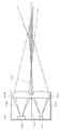
図12および図13は、それぞれ発散光学系および集光光学系による検出の原理を模式的に示すものである。各図において、101は投光素子であり、102は受光素子であり、100Aは投光レンズであり、100Bは受光レンズである。投光レンズ100Aおよび受光レンズ100Bは、1つのレンズ部材として連結されて、内部に2つの導光路105A,105Bを有するレンズホルダ103の開放端面に装着されている。投光レンズ100Aは導光路105Aの前面に、受光レンズ100Bは導光路105Bの前面に、それぞれ配置された状態となる。投光素子101および受光素子102は、それぞれ導光路105A,105Bの後端位置に図示しない基板に搭載された状態で支持される。
図12および図13では、投光素子101からの検出光を一点鎖線により示すと共に、受光素子102に入射する光を二点鎖線により示す。
図12に示すように、発散光学系では、投光レンズ100Aから出た検出光が広い範囲に広がり、受光レンズ100Bも広い範囲から光を集める。これにより、図12中の斜線部分に示すように、センサの近傍で大きく広がる検出エリアを設定することができる。
図12に示すように、発散光学系では、投光レンズ100Aから出た検出光が広い範囲に広がり、受光レンズ100Bも広い範囲から光を集める。これにより、図12中の斜線部分に示すように、センサの近傍で大きく広がる検出エリアを設定することができる。
一方、集光光学系では、図13に示すように、投光レンズ100Aから出た検出光が所定の場所で集光する。受光対象の反射光の範囲も、センサから遠ざかるにつれて狭められるので、図13中の斜線部分に示すように、検出エリアは、光学系の中心軸付近に限定される。また、センサの近傍の位置では、投光の範囲と受光の範囲とが交わらないので、不感帯となるエリア(図中の領域110)が生じる。
前述の特許文献2には、発散光学系のセンサでも同様の不感帯が生じることが示されているが、特許文献2に記載のとおり、発散光学系の場合には、レンズの光軸や曲率などの調整によって検出光が広がる範囲を変更することによって、不感帯を小さくすることができる。
上記のとおり、発散光学系を用いたセンサは、センサから相対的に近い場所における検出(以下、「近距離での検出」という。)に適しているが、検出光はセンサから遠ざかるほど拡散して弱められるので、センサから相対的に遠い場所での検出(以下、「遠距離での検出」という。)の精度を確保するのが困難になる。
これに対し、集光光学系を用いたセンサは、光量密度が高められた検出光を遠方に進行させることができる。また、検出光のビーム径が小さくなるので、検出光を受ける面が傾いている場合でも、その傾きに影響されずに、検出光を受光素子に入射可能な方向に反射させることができる。
よって、集光光学系によれば、遠距離での検出を安定して行うことができるが、センサの近傍位置に不感帯が生じるので、近距離での検出には支障が生じる。
よって、集光光学系によれば、遠距離での検出を安定して行うことができるが、センサの近傍位置に不感帯が生じるので、近距離での検出には支障が生じる。
このように、双方の光学系には、それぞれメリットとデメリットとがある。この点に鑑み、特許文献3には、遠距離用の投光素子と近距離用の投光素子とを組み込むと共に、これらの投光素子よりも受光素子を後方に配置することによって、近距離での検出および遠距離での検出の双方を可能にすることが記載されている。
近年は、様々なアプリケーションに適用するために、小型で性能のよいセンサの開発が求められている。また、市場での競争に打ち勝つには、上記の要望を満たすセンサをコストをかけずに生産する必要がある。
特許文献3に記載された発明では、投光素子を2つ組み込むことや、受光素子の位置をずらすことにより、近距離での検出および遠距離での検出の双方が可能になるが、このような構成では、光学系の拡大を招く。また投光素子を増やすと、回路も拡大する上に電力の消費量が増えるので、コスト高になる。
本発明は上記の問題に着目し、光学系に簡易な構成を追加することによって、近距離での検出と遠距離での検出との双方が可能になると共に、小型でコストが削減された反射型光電センサを提供することを、課題とする。
本発明は、投光素子および受光素子と、レンズホルダに装着された投光レンズおよび受光レンズとが、投光素子から投光レンズを介して出射された光に対する反射光の一部が受光レンズを介して受光素子に導かれる関係をもって配備された構成の反射型光電センサに適用される。この反射型光電センサでは、投光素子および投光レンズによって、投光レンズから所定距離を隔てた場所に集光する第1の検出光が出射されると共に、その集光位置の前後の所定範囲における第1の検出光の光路に受光レンズに入る光の光路が交差する。さらに、投光素子を光源として、受光レンズに入る光の光路に対して第1の検出光が交差する範囲より前の位置で当該受光レンズに入る光の光路に交差する第2の検出光を発生させる手段が、レンズホルダに装着またはレンズホルダの一部として配備される。
上記の構成によれば、第1の検出光によって、センサからある程度離れた範囲に検出エリアが設定されると共に、この第1の検出光による検出エリアより前の位置に第2の検出光による検出エリアが設定される。よって、近距離での検出と遠距離での検出との双方を実行することが可能になる。また第2の検出光は第1の検出光と同じ投光素子を光源とするので、光学系が大幅に拡張したり、投光用の回路が複雑になることもない。よって、センサが大型化するのを防ぐことができる。
上記の反射型光電センサの第1の実施形態での投光レンズは、集光レンズによるレンズ本体と、このレンズ本体の裏面の一部から突出する投光側突出部とを具備する。投光側突出部には、投光レンズと受光レンズとの並び方向に沿って傾斜する傾斜面が含まれ、当該投光側突出部およびこれに連なるレンズ本体の一部が第2の検出光を発生させる手段として機能する。
さらに第1の実施形態では、受光レンズについても同様に、集光レンズによるレンズ本体と、このレンズ本体の裏面の一部から突出する受光側突出部とを具備する構成にすることができる。この場合の受光側突出部にも、投光レンズと受光レンズとの並び方向に沿って傾斜する傾斜面が含まれ、当該受光側突出部およびこれに連なるレンズ本体の一部が、受光レンズに入った第2の検出光の反射光を受光素子に導く手段として機能する。
上記の投光側突出部や受光側突出部は、傾斜面の傾斜方向を長さ方向とする幅狭のレンズ体とするのが望ましい。このレンズ体は、対応するレンズに対して少なくとも1個設けることができる。また、突出部が複数設けられる場合には、それぞれの位置に応じて傾斜面の向きを調整して、各傾斜面を介した光がレンズ本体の中央部に集まるようにしてもよい。
第1の実施形態は、集光レンズを本体とする投光レンズの裏面に投光側突出部を設けることによって、この投光レンズに光を発散する機能を加えたものである。レンズの裏面での突出であれば、投光素子と投光レンズとの間の導光路に突出部を位置づけることができるので、光学系が拡大するおそれがない。また加工も容易である。
一方、第2,第3の実施形態では、投光レンズおよび受光レンズとして集光レンズを使用し、他の部材によって、第2の検出光を発生させる。
第2の実施形態では、レンズホルダの前端部に、投光レンズの一部に対向する箇所から突出する投光側突出部を備えたカバー体が装着される。この投光側突出部には、投光レンズと受光レンズとの並び方向に沿って傾斜する傾斜面が含まれ、当該投光側突出部およびこれに連なるカバー体の一部が第2の検出光を発生させる手段として機能する。
さらに、第2の実施形態では、カバー体の受光レンズの一部に対向する箇所にも、同様の傾斜面を有する受光側突出部を設けることができる。この受光側突出部およびこれに連なるカバー体の一部が、カバー体に入った第2の検出光の反射光の光路を、受光レンズを介して受光素子へと向かう方向に変更する手段として機能する。
第2の実施形態における投光側突出部や受光側突出部も、傾斜面の傾斜方向を長さ方向とする幅狭のレンズ体とするのが望ましい。このレンズ体は、対応するレンズに対して少なくとも1個設けることができる。また、突出部は、カバーの背面(投光レンズや受光レンズに対向する側の面)に設けても良いし、カバーの前面(検出光が出射される面)に設けてもよい。
第2の実施形態によれば、レンズホルダの前端部に装着するカバー体に簡易な構成を追加することにより、レンズホルダ内の主要な光学系の構成を変更することなく、第2の検出光を発生させることが可能になる。
第3の実施形態では、レンズホルダの投光素子側の内壁面に、投光素子から内壁面に向かう光を投光レンズに向かう方向へと屈折させる光学部材が設けられる。この光学部材および投光レンズのうちの当該光学部材が屈折させた光を受ける部分が、第2の検出光を発生させる手段として機能する。
さらに、第3の実施形態では、レンズホルダの受光素子側の内壁面に、受光レンズに入った後に受光素子側の内壁面へと向かう光を受光素子へと導くための第2の光学部材を設けることができる。
第3の実施形態によれば、レンズホルダの内壁面に設けられた光学部材と集光レンズによる投光レンズとによって第2の検出光を発生させるので、レンズホルダ内の光学系の構成を変更することなく、第2の検出光を発生させることが可能になる。
本発明によれば、集光光学系による第1の検出光では検出することができないセンサの近傍の領域に第2の検出光を導くことにより、近距離での検出および遠距離での検出の双方が可能になる。第2の検出光は、第1の検出光と同じ投光素子を光源とするもので、レンズホルダに装着される部材(レンズやカバーなど)やレンズホルダ自体に簡単な構成を追加することによって第2の検出光を発生させることができる。
よって、センサを大型にすることなく、検出能力を高めることができる。さらに、コスト高になることがないので、手頃な価格での提供が可能になる。
よって、センサを大型にすることなく、検出能力を高めることができる。さらに、コスト高になることがないので、手頃な価格での提供が可能になる。
図1は、本発明が適用された反射型光電センサの光学系の構成を、検出の原理と共に示す。
この実施例の光学系には、投光素子1および受光素子2と、これらの素子1,2の前に配備されたレンズ部材3と、レンズ部材3を前端部で支持するレンズホルダ4とが含まれる。投光素子1および受光素子2は後記する回路基板5に搭載されて、レンズホルダ4の背後に配備される。レンズホルダ4の背面には、投光素子1および受光素子2に対応する箇所にそれぞれ開口部41,42が設けられる。またレンズホルダ4の内部には壁部40が設けられ、この壁部40によって、レンズホルダ4内の空間が投光用の導光路43Aと受光用の導光路43Bとに二分される。このレンズホルダ4の構成に鑑み、図1をはじめとする各図では、壁部40の中心位置に対応する位置に、光学系の中心軸Cを設定する。
この実施例の光学系には、投光素子1および受光素子2と、これらの素子1,2の前に配備されたレンズ部材3と、レンズ部材3を前端部で支持するレンズホルダ4とが含まれる。投光素子1および受光素子2は後記する回路基板5に搭載されて、レンズホルダ4の背後に配備される。レンズホルダ4の背面には、投光素子1および受光素子2に対応する箇所にそれぞれ開口部41,42が設けられる。またレンズホルダ4の内部には壁部40が設けられ、この壁部40によって、レンズホルダ4内の空間が投光用の導光路43Aと受光用の導光路43Bとに二分される。このレンズホルダ4の構成に鑑み、図1をはじめとする各図では、壁部40の中心位置に対応する位置に、光学系の中心軸Cを設定する。
この実施例のレンズ部材3は、投光レンズ3Aと受光レンズ3Bとを連結させた構成のものである。両レンズ3A,3Bの境界部分には、壁部40に対応する幅の孔部36(後記する図3,図4を参照。)が形成されており、この孔部36に壁部40を挿入し、両側縁をレンズホルダ4の内壁面の段部(図示せず。)に当接させることにより、レンズ部材3はレンズホルダ4の前端部に支持された状態となる。
投光レンズ3Aと受光レンズ3Bとは、中心軸Cを基準に対称な形状となるので、細部の構成を同じ符号で示すことにする。この実施例のレンズ3A,3Bは、それぞれ前面を凸面とするレンズ本体30と、このレンズ本体30の背面の一部から突出する突出部31とを有する。レンズ本体30の背面の突出部31を除く部分は平坦面となる。
突出部31は、レンズ3A,3Bの並び方向に沿う方向を長さ方向とする幅狭のレンズ体であって、他方のレンズに近づくにつれて厚みが増す。具体的には、突出部31の両側面が三角形となり、各側面の間の幅狭の背面32が、投光レンズ3Aと受光レンズ3Bとの並び方向に沿って傾斜する傾斜面となる。
各レンズ本体30の主要部は集光レンズであるが、突出部31に厚み方向で連なる箇所と突出部31とによって、光を発散させる機能が生じる。投光素子1から出た光は、導光路43Aを広がりながら進行して投光レンズ3Aの背面全体に照射されるが、突出部31を通過した光とそれ以外の場所を通過した光とでは、それぞれ辿る光路が異なる。受光レンズ3Bでも、同様に、突出部31に対応する箇所とそれ以外の箇所とでは、集光対象の光の光路が異なるものになる。
図1では、投光レンズ3A内の集光レンズの機能により生じる検出光を「第1の検出光」として、その主要な光路を一点鎖線により示し、突出部31を通過した光により生じる検出光を「第2の検出光」として、その主要な光線を点線により示す(後記する図8~図11でも同じ。)。また、図中、検出対象物として、平板形状のワークWF,WNを示す。
投光素子1から投光レンズ3Aに入った光の大半は緩やかに屈折して、中心軸Cに徐々に近づきながら進行し、センサからかなり離れた地点で中心軸Cに到達する。中心軸Cに近い位置に進んだ第1の検出光を受けたワークWFからの反射光は、中心軸Cから徐々に離れながら進行して受光レンズ3Bに入り、受光素子2へと導かれる。
一方、投光レンズ3Aの裏面の突出部31に導かれた光は、その傾斜面32がプリズムとして機能するため大きく屈折してレンズ本体30に入り、凸状の前面へと導かれる。この結果、前面の突出部31に対応する帯領域から、周囲よりも急な角度で屈折する光が出射される。この光は、第1の検出光を受光可能な範囲よりも前方の位置で中心軸Cや受光側の光路に交差する第2の検出光となる。
受光レンズ3Bでも、同様の機能により、第1の検出光により検出できる範囲より前に位置するワークWNで反射した第2の検出光を、レンズ本体30から突出部31を介して受光素子2へと導く。
上記のとおり、この実施例の投光レンズ3Aおよび受光レンズ3Bは集光機能を有するレンズ本体30の一部に発散機能が付加されたものである。言うなれば、これらのレンズ3A,3Bと投光素子1および受光素子2とにより、集光光学系と発散光学系との双方の要素を併せ持つハイブリッド型の光学系が設定される。
この光学系では、1つの投光素子1からの光により2種類の検出光を発生させることができると共に、各検出光に対する反射光を受光することができる。
この光学系では、1つの投光素子1からの光により2種類の検出光を発生させることができると共に、各検出光に対する反射光を受光することができる。
各レンズ本体30の主要部は集光レンズであるので、第1の検出光を十分な強度で集光させて、遠距離での検出を安定させることができる。
光を発散させる機能を有する箇所の割合は小さいが、裏面の突出部31の傾斜角度や前面の曲率などの調整によって、後述するように、第1の検出光のみによる検出では不感帯となるセンサ近傍の領域に第2の検出光を発散させることが可能になる。よって、近距離での検出精度を確保することも可能になる。
光を発散させる機能を有する箇所の割合は小さいが、裏面の突出部31の傾斜角度や前面の曲率などの調整によって、後述するように、第1の検出光のみによる検出では不感帯となるセンサ近傍の領域に第2の検出光を発散させることが可能になる。よって、近距離での検出精度を確保することも可能になる。
以下、図1に示した光学系を具体化した実施例について、詳細に説明する。
図2は、光学系の全体構成(レンズホルダ4内の構成)を示す斜視図であり、図3は、この光学系で使用されるレンズ部材3の背面側の構成を示す斜視図である。さらに図4では、当該レンズ部材3の正面図(1)、背面図(2)、および側面図(3)を並べて示す。
図2は、光学系の全体構成(レンズホルダ4内の構成)を示す斜視図であり、図3は、この光学系で使用されるレンズ部材3の背面側の構成を示す斜視図である。さらに図4では、当該レンズ部材3の正面図(1)、背面図(2)、および側面図(3)を並べて示す。
図2において、10は投光素子1を含むパッケージであり、20は受光素子2を含むパッケージである。なお、受光素子2を収容するパッケージ20は、受光量信号を処理する回路が組み込まれたフォトICとして構成することができる。
各パッケージ10,20は回路基板5に支持および電気接続される。また、図2の例では、レンズホルダ4の周壁がやや延長されて、その延長部分にパッケージ10,20を保護するための保護ホルダ6が一体に設けられている。回路基板5は、レンズホルダ4の背面側の開口端面と図示しない基板ホルダとの間に支持され、これにより基板5上のパッケージ10,20が保護ホルダ6内に位置づけられる。
この実施例のレンズ部材3は、投光レンズ3Aと受光レンズ3Bとを、両側縁に延びる一対の連結部33,34により連結した構成のものである。投光レンズ3Aと受光レンズ3Bとは、各連結部33,34によって、若干の隙間36を挟んで対向する状態で連結される。この隙間36が壁部40を挿入するための孔部として機能する。また、一方の連結部33の中央部には、外側に突出する突片35が形成される。
上記構成のレンズ部材3は、レンズホルダ4の前面の開口端縁よりやや内部に入った位置に支持される。各連結部33,34はレンズホルダ4の内壁に設けられた段部に支持される。また、突片35が形成された連結部33に対応する段部には、突片35を挿入するための凹部が連続形成されている。この凹部と突片35との係合と、挿入孔36に壁部40を貫通させることとによって、レンズホルダ4へのレンズ部材3の位置合わせが完了する。
なお、図2には示していないが、後記するように、レンズホルダ4の前面の開口端縁には、透光性を有するカバー7が装着される。このカバー7は、レンズ部材3やレンズホルダ4の内部に埃などが付着するのを防ぐためのものであるが、若干の曲率をもつレンズ部材をカバーとして、各検出光の光路を調整してもよい。
また、図3の斜視図や図4(3)の側面図によれば、この実施例のレンズ部材3では、突出部31の傾斜面32のうち、中心軸C側の端部(一番厚みのある箇所)を切り欠いて平坦面にしているが、図1の例と同様に、突出部31の背面全体を傾斜面にしてもよい。また、傾斜面32の傾斜の変化は直線状に限らず、曲面状に変化させてもよい。
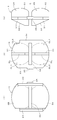
図4(2)の背面図では、各レンズ3A,3Bの光の発散機能を持つ箇所を符号DLにより示し、その両側の収束する光を出射する箇所を、それぞれ符号CL1,CL2により示す。以下、説明の便宜のため、DLを発散レンズと呼び、CL1,CL2を集光レンズと呼ぶ。
この図4(2)に示すように、この実施例のレンズ3A,3Bでは、レンズ本体30の短手側の幅の中心部に幅狭の発散レンズDL(突出部31およびレンズ本体30内で厚み方向に沿って突出部31に連なる部分)が位置し、これを挟んで、面積の広い集光レンズCL1,CL2が位置する。この構成の投光レンズ3Aによれば、各集光レンズCL1,CL2から十分な強度で第1の検出光を出射することができるので、遠距離での検出精度を確保することができる。また、レンズ本体30の前面内の最も前方にせり出す中心部の帯領域から発散光を出射することができるので、小さな領域であっても十分な発散機能を確保することができ、第2の検出光による検出精度も確保することができる。
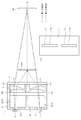
図5は、上記構成の光学系における各検出光の光路とこれらにより設定される検出エリアとの関係を模式的に表したものである。具体的には、集光レンズCL1,CL2による第1の検出光を一点鎖線で表し、その反射光を二点鎖線で表す一方、発散レンズDLによる第2の検出光とその反射光をそれぞれ異なる塗りパターンにより表す。
また図5では、レンズホルダ4内のレンズ部材3を、外側の輪郭線のみにより示している。この輪郭線から明らかなように、投光レンズ3Aおよび受光レンズ3Bの各傾斜面32は、それぞれ投光素子1および受光素子2の光路の幅全体に対応する範囲に位置づけられる。
図5によれば、投光レンズ3A内の集光レンズCL1,CL2による第1検出光は、光学系の中心軸C上のa点を中心とする範囲に集光する。この第1検出光の進行範囲(一点鎖線で示す範囲)と、受光レンズ3B内の集光レンズCL1,CL2を介して受光可能な光が進行する範囲(二点鎖線で示す範囲)とが重なり合う領域R1(斜線パターンで示す。)が、第1検出光による検出エリアとなる。
以下、この検出エリアR1を第1検出エリアR1と呼び、当該第1検出エリアR1の前方で中心軸Cに交わる点をb点とする。
以下、この検出エリアR1を第1検出エリアR1と呼び、当該第1検出エリアR1の前方で中心軸Cに交わる点をb点とする。
投光レンズ3A内の発散レンズDLからの第2検出光は、前面の帯状凸面から中心軸Cに向かう方向に大きく屈折する。図5の例では、この第2検出光の光束が、第1検出エリアR1より前方の位置で、中心軸Cおよび受光レンズ3Bの光路に交差するように、突出部31の傾斜角度やレンズ本体30の前面の曲率を調整している。受光レンズ3Bも投光レンズ3Aと同様の構成を有するので、受光レンズ3B側の発散レンズDLを介して受光素子2へと導かれる反射光の範囲も、第1検出エリアR1より前方の位置で中心軸Cに交差するようになる。
図5では、第2の検出光の進行範囲(点線のパターンで示す。)と、受光レンズ3B内の発散レンズDLにより受光可能な光が進行する範囲(網点パターンで示す。)とが重なり合う領域R2の境界線を極太線にして示す。この領域R2が第2検出光による検出エリアとなる。以下、この検出エリアR2を第2検出エリアR2と呼ぶ。
第2検出エリアR2は、センサの直近位置から広がって第1検出エリアR1に連なっているので、双方の検出エリアR1,R2を合わせた範囲、すなわち第2検出エリアR2の前端位置から第1検出エリアR1の後端位置(図5には示さず。)までの範囲で物体を検出することが可能である。
2つの検出エリアR1,R2により保証できる検出距離は、条件により種々に変動するが、一例として、センサから約40mm離れた場所に第1の検出光が集光する場合には、センサから70~80mm離れた範囲まで、安定した検出が可能であった。また、センサの直近の位置から第1の検出光の集光点までの範囲でも、安定した検出が可能であった。
一方、センサから100mm以上離れた場所に置かれたワークに対し、「物体あり」の検出結果が得られることはなかった。
一方、センサから100mm以上離れた場所に置かれたワークに対し、「物体あり」の検出結果が得られることはなかった。
なお、図5によれば、第2の検出光の進行範囲は、第1検出エリアR1より前の位置で、受光レンズ3B内の集光レンズCL1,CL2を介して受光される光の範囲(二点鎖線)を横切っているので、この二点鎖線の範囲と第2の検出光の進行範囲とが交差する領域内で物体を検出することが可能である。よって、受光レンズ3Bに発散機能を設けずに集光機能のみとしても、ある程度大きなワークであれば、第1検出領域R1より前方での検出が可能になる。
しかしながら、受光レンズ3B内に発散レンズDLを設ければ、センサの近傍の広い範囲で安定した検出を行うことができる。また、センサ近傍でも、中心軸C付近での検出の精度が確保されるので、微小な物体でも、安定して検出することが可能になる。
しかしながら、受光レンズ3B内に発散レンズDLを設ければ、センサの近傍の広い範囲で安定した検出を行うことができる。また、センサ近傍でも、中心軸C付近での検出の精度が確保されるので、微小な物体でも、安定して検出することが可能になる。
つぎに、上記実施例の比較例として、集光光学系と発散光学系との機能を併せ持つ光学系の他の例を図6に示す。
この例では、本体の裏面に複数の凹部301が一列に形成された構成のレンズ300A,300Bを使用する。各凹部301は、レンズ本体の厚み方向に沿う一面が傾斜する形状に形成されている。
この例では、本体の裏面に複数の凹部301が一列に形成された構成のレンズ300A,300Bを使用する。各凹部301は、レンズ本体の厚み方向に沿う一面が傾斜する形状に形成されている。
この構成によれば、投光レンズ300Aでは、投光素子1から凹部301に導かれた光を、その傾斜面によって中心軸Cの方に屈折させる。また受光レンズ300Bでも、図中の斜め下方からレンズ本体に入って凹部301の傾斜面に到達した光を屈折させて受光素子2の方へと導く。よって、凹部301の配列に厚み方向において連なる箇所と凹部301の配列とにより、センサの近傍に発散光を出射することができる。
しかし、図6中の極太矢印Pに示すように、この構成の投光レンズ3Aでは、微小な凹部301内で多重反射した光が中心軸Cに向かう方向とは異なる方向からレンズ本体に入射するなどして、各検出光の光路として想定している範囲から外れた方向に光が出射される可能性がある。受光レンズ3Bでも、受光可能な反射光光路として想定している範囲とは異なる方向からの光が、凹部301で反射するなどして受光素子2へと導かれるおそれがある。
このように、レンズ本体の裏面の微小な凹部301の配列により光を発散させる構成を採用すると、検出の精度を確保するのが困難になる。しかも、微小な凹部301を有するレンズ部材を成型するには複雑な金型が必要になり、コスト高を招く。
これに対し、図1~5に示したレンズ部材3では、レンズ本体30の裏面に、その径方向に沿って一連に延びる突出部31を形成するので、金型を複雑にすることなく成型することができる。また、傾斜面32を突出部31のほぼ全域に形成することにより、図5に示すように、投光素子1からの光や受光素子2への光が広がる範囲全域に傾斜面を合わせることができるので、傾斜面32と切り欠き部分との境界の角部などに照射された光が想定外の方向に進むおそれもない。よって、検出の精度を確保することができる。
なお、上記の実施例では、レンズ本体30の中央部に1つのみ突出部31を形成したが、突出部31の個数や形成位置はこれに限定されるものではない。
図7では、レンズ部材3内の1つのレンズ(投光レンズ3Aまたは受光レンズ3B)を図示の対象として、突出部31の形成に関する変形例を示す。
まず、図7(1-a)および図7(1-b)は、先の図1~4の実施例に準じた構成のレンズの背面図および側面図である。突出部31は、レンズ本体30の短手方向の幅の中央部に形成され、厚み部分を徐々に変化させることにより、裏面32が傾斜する。これが突出部31の基本構成である。
図7(2)(3)の例は、上記の基本構成を維持しながら、突出部の個数を増やしたものである。
図7(2)の例では、レンズ本体30の中央部にではなく、一対の突出部31a,31bを、レンズ本体30の各側縁に沿って配置している。図7(3)の例では、図7(1)と同様の中央部の突出部31と、図7(2)に示した突出部31a,31bとの計3個を配置している。
図7(2)の例では、レンズ本体30の中央部にではなく、一対の突出部31a,31bを、レンズ本体30の各側縁に沿って配置している。図7(3)の例では、図7(1)と同様の中央部の突出部31と、図7(2)に示した突出部31a,31bとの計3個を配置している。
図7(2)(3)の例に限らず、集光光学系による検出に影響が及ばない範囲で、突出部31の個数を増やすことにより、発散反射型の光学系による第2の検出光の強度を高め、近距離での検出を安定させることができる。
また、突出部31の個数を増やした場合には、図7(4)に示すように、両側の突出部31a,31bの断面形状を直角三角形として、その斜辺に対応する面を外側に位置づけると共にこの面を傾斜させてもよい。このようにすれば、投光レンズ3Aでは、各突出部31,31a,31bの傾斜面を通過した光をレンズ本体30の中心部に集めて出射させることができる。また、受光レンズ3Bでも、投光レンズ3Aとは逆の経路に従って、レンズ本体30の中心部に入射して各突出部31,31a,31bの傾斜面に達する反射光を、受光素子2へと集めることができる。
また、突出部31の個数を増やした場合には、図7(4)に示すように、両側の突出部31a,31bの断面形状を直角三角形として、その斜辺に対応する面を外側に位置づけると共にこの面を傾斜させてもよい。このようにすれば、投光レンズ3Aでは、各突出部31,31a,31bの傾斜面を通過した光をレンズ本体30の中心部に集めて出射させることができる。また、受光レンズ3Bでも、投光レンズ3Aとは逆の経路に従って、レンズ本体30の中心部に入射して各突出部31,31a,31bの傾斜面に達する反射光を、受光素子2へと集めることができる。
以上に記述した第1実施例の利点をまとめる。
この第1実施例では、裏面に突出部31を有するレンズ部材3を使用するので、投光レンズ3Aおよび受光レンズ3Bのレンズ本体30の大きさを従来と同様に維持することができる。また、突出部31はレンズホルダ4の導光路43A,43B内に入る大きさであるので、レンズホルダ4の構成や大きさを変更する必要もない。
よって、光学系の大きさを従来と同程度に維持することができる。その一方で、2種類の検出光によって遠距離での検出および近距離での検出の双方を実施することができるので、従来の限定反射型センサや拡散反射型センサと比較すると、検出能力が大幅に高められる。
この第1実施例では、裏面に突出部31を有するレンズ部材3を使用するので、投光レンズ3Aおよび受光レンズ3Bのレンズ本体30の大きさを従来と同様に維持することができる。また、突出部31はレンズホルダ4の導光路43A,43B内に入る大きさであるので、レンズホルダ4の構成や大きさを変更する必要もない。
よって、光学系の大きさを従来と同程度に維持することができる。その一方で、2種類の検出光によって遠距離での検出および近距離での検出の双方を実施することができるので、従来の限定反射型センサや拡散反射型センサと比較すると、検出能力が大幅に高められる。
また、上記のレンズ部材3の成型は容易であるので、コストが高くなることもない。よって、小型で検出能力が高められた反射型光電センサを、手頃な価格で提供することが可能になる。
つぎに、図8~11を参照して、レンズ部材3以外の手段によって、同様の2種類の検出光を発生させる光学系に関する実施例を、4例説明する。なお、いずれの例の光学系も、基本的な構成は図1と同様であるので、対応する箇所を同じ符号で示すことにより、説明を省略または簡単にする。各図において、一点鎖線は第1の検出光およびその反射光の光路であり、点線は第2の検出光およびその反射光の光路である。また、センサから離れた場所にあるワークをWFとし、センサに近い場所にあるワークをWNとする。
図8に示す実施例の光学系は、レンズホルダ4の前面に取り付けられるカバー7の裏面に、一対の突出部71,71を形成したものである。図8では、光学系全体の構成を示す図(図8(1))と共に、カバー7の背面図(図8(2))を示す。
図8(2)に示すように、各突出部71は、カバー7の短手方向の幅の中心部に並んでいる。先の実施例のレンズ部材3の突出部31と同様に、各突出部71は、他方の突出部71に近づくにつれて厚みが増し、これにより背面72が傾斜面となる。
カバー7がレンズホルダ4に取り付けられると、図8(1)に示すように、一方の突出部71は投光レンズ3Aの前方に位置し、他方の突出部71は受光レンズ3Bの前方に位置する状態になる。
カバー7がレンズホルダ4に取り付けられると、図8(1)に示すように、一方の突出部71は投光レンズ3Aの前方に位置し、他方の突出部71は受光レンズ3Bの前方に位置する状態になる。
レンズ部材3は、先の実施例と同様に、投光レンズ3Aと受光レンズ3Bとを連ねて構成されるが、この実施例のレンズ3A,3Bには、一般的な集光レンズが用いられる。
投光素子1から出て投光レンズ3Aに入った光の大半は緩やかに屈折してカバー7を通過し、第1の検出光として遠方に向けて出射される。中心軸Cに近い位置に進行した第1の検出光を受けたワークWFからの反射光は、中心軸Cを徐々に離れながら進行してカバー7および受光レンズ3Bを通過し、受光素子2へと導かれる。
投光素子1から出て投光レンズ3Aに入った光の大半は緩やかに屈折してカバー7を通過し、第1の検出光として遠方に向けて出射される。中心軸Cに近い位置に進行した第1の検出光を受けたワークWFからの反射光は、中心軸Cを徐々に離れながら進行してカバー7および受光レンズ3Bを通過し、受光素子2へと導かれる。
投光素子1および投光レンズ3Aを介した光の一部は、カバー7の突出部71の傾斜面72に照射され、そのプリズム作用によって大きく屈折して、センサの近傍位置で中心軸Cや受光側の光路に交差する。この光が第2の検出光として機能する。
センサの近傍に位置するワークWNで反射した第2の検出光は、受光素子2へと導くことができない方向に進むが、カバー7の突出部71に入った反射光は、傾斜面72で大きく屈折して受光レンズ3Bに入り、受光素子2へと導かれる。これにより、第1の検出光により検出可能な範囲より前方に位置するワークWNを第2の検出光により検出することが可能になる。
図9の実施例も、突出部を有するカバー7を使用するものであるが、この例では、カバー7の前面側に一対の突出部71a,71aが形成される。各突出部71aの厚みは、図8の例とは逆に、他方の突出部71aに近づくにつれて小さくなる。したがって、傾斜面72aの傾斜の方向も、図8の傾斜面72とは逆になる。
上記の構成でも、投光素子1から出て投光レンズ3Aに入った光の大半は緩やかに屈折してカバー7を通過し、第1の検出光として遠方に向けて出射される。中心軸Cに近い位置に進行した第1の検出光を受けたワークWFからの反射光は、中心軸Cを徐々に離れながら進行してカバー7および受光レンズ3Bを通過し、受光素子2へと導かれる。
投光レンズ3Aからカバー7の突出部71aに入った光は、その傾斜面72aで大きく屈折して、センサの近傍位置で中心軸Cや受光側の光路に交差する状態になる。この光が第2の検出光として機能する。
センサの近傍に位置するワークWNで反射した第2の検出光は、受光素子2へと導くことができない方向に進むが、受光側の突出部71aに達した反射光は、その傾斜面72aによって大きく屈折し、受光レンズ3Bを介して受光素子2へと導かれる光に転換される。これにより、第1の検出光により検出可能な範囲より前方に位置するワークWNを第2の検出光により検出することが可能になる。
センサの近傍に位置するワークWNで反射した第2の検出光は、受光素子2へと導くことができない方向に進むが、受光側の突出部71aに達した反射光は、その傾斜面72aによって大きく屈折し、受光レンズ3Bを介して受光素子2へと導かれる光に転換される。これにより、第1の検出光により検出可能な範囲より前方に位置するワークWNを第2の検出光により検出することが可能になる。
図10の実施例では、レンズホルダ4内の各導光路43A,43Bにそれぞれミラー8A,8Bを設けることによって、第2の検出光の光路を確保したものである。各ミラー8A,8Bは、それぞれ対応する導光路43A,43Bの周壁側の内壁面に装着、または前面を露出させた状態で内壁面に埋め込まれる。
この実施例の投光レンズ3Aおよび受光レンズ3Bも通常の集光レンズである。また、図10では示していないが、レンズホルダ4の開口端面に装着されるカバー7も、突出部のない通常の形態のものである。
投光レンズ3Aに入る光の大半は緩やかに屈折して、中心軸Cに徐々に近づく第1の検出光として出射され、遠方の地点に集光する。しかし、投光素子1から導光路43Aの周壁に向かった光はミラー8Aで正反射して大きく屈折する。これにより、最初の図1の実施例の傾斜面32によるのと同様の効果が生じ、レンズ3Aから大きく屈折する光が出射される。この光が第2の検出光として機能する。
中心軸Cに近い位置に進行した第1の検出光を受けたワークWFからの反射光は、中心軸Cを徐々に離れながら進行して受光レンズ3Bを通過し、受光素子2へと導かれる。センサの近傍で反射した第2の検出光は、受光レンズ3Bを通過して導光路43Bの周壁へと導かれる可能性が高いが、内壁面のミラー8Bでこの光を受光素子2の方へと反射させて、受光素子2に結像させることができる。
よって、この構成でも、レンズ部材3やカバー7に突出部を設けた構成と同様に、第2の検出光を発生させると共に、その反射光を高い確度で受光し、遠距離での検出と共に近距離での検出を可能にすることができる。
よって、この構成でも、レンズ部材3やカバー7に突出部を設けた構成と同様に、第2の検出光を発生させると共に、その反射光を高い確度で受光し、遠距離での検出と共に近距離での検出を可能にすることができる。
図11の実施例も、図10の実施例と同じく、投光素子1から周壁に向かう光を投光レンズ3Aに向かう方向へと屈折させる光学部材を用いるものである。この実施例の投光側の導光路43Aには、ミラー8Aに代えて、前後に開口部91,92を有する絞り部材9が設けられる。この絞り部材9は、光通路を限定することにより光を集光するもので、導光路43Aの後端部の周壁の内壁面に一体に設けられる。
この構成により、絞り部材9では、投光素子1からレンズホルダ4の周壁に向かって進行した光を背面側の開口部92から受け入れて集光し、これを前方の開口部91を介して前方に導く。この方式により、図10の例のミラー8Aからの反射光と同様の方向からの光を投光レンズ3Aに入射させて、これを投光レンズ3Aで大きく屈折させ、センサの近傍位置で中心軸Cを横切る第2の検出光として出射することが可能になる。
受光側の導光路43Bには、図10の例と同様の位置にミラー8Bが設けられている。よって、図10の例と同様に、センサの近傍位置で反射して受光レンズ3Bを介して周壁側の内壁面に到達した光をミラー8Bで反射させて受光素子2へと導くことができる。
図10および図11に示した実施例は、集光光学系の構成を変更することなく、レンズホルダ4に簡単な光学部材を付加することによって、近距離検出用の第2の検出光の光路を確保するものである。いずれの光学部材も、レンズホルダ4の内部に設けられるので、レンズホルダ4を従来の大きさで維持することができる。またいずれも簡易な構成の部材であるので、コストが大きく上昇するおそれもない。
よって、図10,11の実施例でも、小型で検出能力の向上した反射型センサを、手頃な価格で提供することが可能になる。
よって、図10,11の実施例でも、小型で検出能力の向上した反射型センサを、手頃な価格で提供することが可能になる。
なお、図10,11の実施例において、第2の検出光に対し、導光路43Bの周壁部に向かうことなく、受光レンズ3Bを介して受光素子2に入射する反射光の割合が高い場合には、導光路43Bにミラー8Bを配備しなくともよい。また、図8,9に示した実施例でも、同様に、カバー7の投光側に対応する箇所にのみ、突出部71または71aを取り付けるにとどめてもよい。
いずれの実施例でも、拡散光学系に関する受光側の機能は、近距離での検出精度を高める目的で導入すればよい。
いずれの実施例でも、拡散光学系に関する受光側の機能は、近距離での検出精度を高める目的で導入すればよい。
1 投光素子
2 受光素子
3 レンズ部材
3A 投光レンズ
3B 受光レンズ
4 レンズホルダ
7 カバー
30 レンズ本体
31,71,71a 突出部
32,72,72a 傾斜面
8A,8B ミラー
9 絞り部材
2 受光素子
3 レンズ部材
3A 投光レンズ
3B 受光レンズ
4 レンズホルダ
7 カバー
30 レンズ本体
31,71,71a 突出部
32,72,72a 傾斜面
8A,8B ミラー
9 絞り部材
Claims (9)
- 投光素子および受光素子と、レンズホルダに装着された投光レンズおよび受光レンズとが、投光素子から投光レンズを介して出射された光に対する反射光の一部が受光レンズを介して受光素子に導かれる関係をもって配備された反射型光電センサにおいて、
前記投光素子および投光レンズによって、投光レンズから所定距離を隔てた場所に集光する第1の検出光が出射されると共に、その集光位置の前後の所定範囲における第1の検出光の光路に前記受光レンズに入る光の光路が交差し、
前記投光素子を光源として、前記受光レンズに入る光の光路に対して前記第1の検出光が交差する範囲より前の位置で当該受光レンズに入る光の光路に交差する第2の検出光を発生させる手段が、前記レンズホルダに装着またはレンズホルダの一部として配備される、ことを特徴とする反射型光電センサ。 - 前記投光レンズは、集光レンズによるレンズ本体と、このレンズ本体の裏面の一部から突出する投光側突出部とを具備し、
前記投光側突出部には、前記投光レンズと受光レンズとの並び方向に沿って傾斜する傾斜面が含まれており、当該投光側突出部およびこれに連なるレンズ本体の一部が前記第2の検出光を発生させる手段として機能する、請求項1に記載された反射型光電センサ。 - 前記受光レンズは、集光レンズによるレンズ本体と、このレンズ本体の裏面の一部から突出する受光側突出部とを具備し、
前記受光側突出部には、前記投光レンズと受光レンズとの並び方向に沿って傾斜する傾斜面が含まれており、当該受光側突出部およびこれに連なるレンズ本体の一部が、前記受光レンズに入った第2の検出光の反射光を受光素子に導く手段として機能する、請求項2に記載された反射型光電センサ。 - 前記投光レンズおよび受光レンズは集光レンズであり、
前記レンズホルダの前端部には、投光レンズの一部に対向する箇所から突出する投光側突出部を備えたカバー体が装着され、
前記投光側突出部には、前記投光レンズと受光レンズとの並び方向に沿って傾斜する傾斜面が含まれており、当該投光側突出部およびこれに連なるカバー体の一部が前記第2の検出光を発生させる手段として機能する、請求項1に記載された反射型光電センサ。 - 前記カバー体には、さらに前記受光レンズの一部に対向する箇所から突出する受光側突出部が含まれると共に、受光側突出部に、前記投光レンズと受光レンズとの並び方向に沿って傾斜する傾斜面が含まれており、
前記受光側突出部およびこれに連なるカバー体の一部が、前記カバー体に入った第2の検出光の反射光の光路を、受光レンズを介して受光素子へと向かう方向に変更する手段として機能する、請求項4に記載された反射型光電センサ。 - 前記投光側突出部は、前記傾斜面の傾斜方向を長さ方向とする幅狭のレンズ体であって、投光レンズに対して少なくとも1個設けられる、請求項2または請求項4に記載された反射型光電センサ。
- 前記投光側突出部および受光側突出部は、前記傾斜面の傾斜方向を長さ方向とする幅狭のレンズ体であって、投光レンズおよび受光レンズに対し、それぞれ少なくとも1個ずつ設けられる、請求項3または請求項5に記載された反射型光電センサ。
- 前記投光レンズおよび受光レンズは集光レンズであり、
前記レンズホルダの投光素子側の内壁面には、前記投光素子から内壁面に向かう光を投光レンズに向かう方向へと屈折させる光学部材が設けられ、当該光学部材および前記投光レンズのうちの当該光学部材が屈折させた光を受ける部分が、前記第2の検出光を発生させる手段として機能する、請求項1に記載された反射型光電センサ。 - 前記レンズホルダの受光素子側の内壁面には、前記受光レンズに入った後に受光素子側の内壁面へと向かう光を受光素子へと導くための第2の光学部材が設けられる、請求項8に記載された反射型光電センサ。
Priority Applications (2)
| Application Number | Priority Date | Filing Date | Title |
|---|---|---|---|
| EP13761483.0A EP2701209B1 (en) | 2012-03-15 | 2013-01-10 | Reflective photoelectric sensor |
| CN201380001777.3A CN103620799B (zh) | 2012-03-15 | 2013-01-10 | 反射型光电传感器 |
Applications Claiming Priority (2)
| Application Number | Priority Date | Filing Date | Title |
|---|---|---|---|
| JP2012059127A JP6003121B2 (ja) | 2012-03-15 | 2012-03-15 | 反射型光電センサ |
| JP2012-059127 | 2012-03-15 |
Publications (1)
| Publication Number | Publication Date |
|---|---|
| WO2013136824A1 true WO2013136824A1 (ja) | 2013-09-19 |
Family
ID=49160746
Family Applications (1)
| Application Number | Title | Priority Date | Filing Date |
|---|---|---|---|
| PCT/JP2013/050271 Ceased WO2013136824A1 (ja) | 2012-03-15 | 2013-01-10 | 反射型光電センサ |
Country Status (5)
| Country | Link |
|---|---|
| EP (1) | EP2701209B1 (ja) |
| JP (1) | JP6003121B2 (ja) |
| CN (1) | CN103620799B (ja) |
| TW (1) | TWI479177B (ja) |
| WO (1) | WO2013136824A1 (ja) |
Cited By (4)
| Publication number | Priority date | Publication date | Assignee | Title |
|---|---|---|---|---|
| EP2866059A3 (en) * | 2013-10-21 | 2015-06-03 | Omron Corporation | Limited-Area reflection type optical sensor and electronic device |
| CN109461662A (zh) * | 2018-09-28 | 2019-03-12 | 深圳赛意法微电子有限公司 | 多点近距离感应器的封装方法 |
| US10627539B2 (en) * | 2017-09-11 | 2020-04-21 | Sick Ag | Optoelectronic sensor system |
| CN114947737A (zh) * | 2021-02-22 | 2022-08-30 | 隆达电子股份有限公司 | 光学检测装置 |
Families Citing this family (12)
| Publication number | Priority date | Publication date | Assignee | Title |
|---|---|---|---|---|
| JP6364840B2 (ja) * | 2014-03-15 | 2018-08-01 | オムロン株式会社 | フォトセンサ |
| EP2966491B1 (en) * | 2014-07-09 | 2022-02-02 | ams AG | Lens assembly, optoelectronic package and method of producing an optoelectronic package with lens assembly |
| JP5968963B2 (ja) * | 2014-08-28 | 2016-08-10 | Idec株式会社 | 光学情報読み取り装置 |
| KR20170115425A (ko) * | 2016-04-07 | 2017-10-17 | 크루셜텍 (주) | 거리 측정 센서 조립체 및 그를 갖는 전자기기 |
| KR101701419B1 (ko) * | 2016-08-17 | 2017-02-02 | 주식회사 오토닉스 | 반사형 이미지 검출 센서 |
| CN106291574B (zh) * | 2016-09-10 | 2019-04-02 | 北醒(北京)光子科技有限公司 | 一种小型红外测距装置 |
| CN108132138A (zh) * | 2017-11-23 | 2018-06-08 | 矽力杰半导体技术(杭州)有限公司 | 光学检测组件 |
| CN108278969B (zh) * | 2018-01-23 | 2020-01-07 | 智恒(厦门)微电子有限公司 | 一种微型光电传感器 |
| JP6904285B2 (ja) * | 2018-03-13 | 2021-07-14 | オムロン株式会社 | 限定反射型センサ |
| JP6889410B2 (ja) | 2018-03-14 | 2021-06-18 | オムロン株式会社 | 光電センサ |
| EP4206735A4 (en) * | 2020-08-28 | 2024-05-22 | Hesai Technology Co., Ltd. | LASER RADAR AND TELEMETRY METHOD |
| JP2026037859A (ja) * | 2024-08-22 | 2026-03-06 | デクセリアルズ株式会社 | 変位センサ |
Citations (5)
| Publication number | Priority date | Publication date | Assignee | Title |
|---|---|---|---|---|
| JPH08255536A (ja) * | 1995-03-15 | 1996-10-01 | Omron Corp | 反射型光電センサ |
| JP3297968B2 (ja) | 1994-09-14 | 2002-07-02 | オムロン株式会社 | 限定反射型光電センサ |
| JP2003204077A (ja) * | 2001-12-28 | 2003-07-18 | Matsushita Electric Works Ltd | 反射型光電センサ |
| JP2010258237A (ja) | 2009-04-24 | 2010-11-11 | Panasonic Electric Works Co Ltd | 反射型光電センサ |
| JP2011107019A (ja) | 2009-11-19 | 2011-06-02 | Yamatake Corp | 光電センサ |
Family Cites Families (12)
| Publication number | Priority date | Publication date | Assignee | Title |
|---|---|---|---|---|
| JPS61280033A (ja) * | 1985-06-06 | 1986-12-10 | Matsushita Electric Ind Co Ltd | 焦点誤差検出装置 |
| JP2672492B2 (ja) * | 1985-12-06 | 1997-11-05 | オムロン株式会社 | 光電スイッチ |
| JPH0713699B2 (ja) * | 1986-07-25 | 1995-02-15 | キヤノン株式会社 | 自動焦点検出用の投光系 |
| US4907026A (en) * | 1986-04-21 | 1990-03-06 | Canon Kabushiki Kaisha | Light projection system for automatic focus detection |
| JP2855744B2 (ja) * | 1989-02-20 | 1999-02-10 | オムロン株式会社 | 反射形光電スイッチ |
| EP1557886A3 (en) * | 2004-01-26 | 2006-06-07 | Matsushita Electric Industrial Co., Ltd. | Solid-state imaging device and camera |
| ATE387620T1 (de) * | 2004-07-22 | 2008-03-15 | Bea Sa | Lichtabtastvorrichtung zur detektion um automatische türen |
| JP3935898B2 (ja) * | 2004-07-22 | 2007-06-27 | 竹中電子工業株式会社 | 光電センサ |
| CN1779486A (zh) * | 2004-11-19 | 2006-05-31 | 南京德朔实业有限公司 | 激光测距装置 |
| CN2811945Y (zh) * | 2005-08-08 | 2006-08-30 | 南京德朔实业有限公司 | 光学测距装置 |
| JP4332566B2 (ja) * | 2007-03-23 | 2009-09-16 | キヤノン株式会社 | 撮像装置 |
| CN102313882B (zh) * | 2011-07-22 | 2015-07-29 | 江苏徕兹光电科技有限公司 | 激光测距仪的光学系统结构 |
-
2012
- 2012-03-15 JP JP2012059127A patent/JP6003121B2/ja active Active
-
2013
- 2013-01-10 EP EP13761483.0A patent/EP2701209B1/en active Active
- 2013-01-10 WO PCT/JP2013/050271 patent/WO2013136824A1/ja not_active Ceased
- 2013-01-10 CN CN201380001777.3A patent/CN103620799B/zh active Active
- 2013-02-25 TW TW102106479A patent/TWI479177B/zh not_active IP Right Cessation
Patent Citations (5)
| Publication number | Priority date | Publication date | Assignee | Title |
|---|---|---|---|---|
| JP3297968B2 (ja) | 1994-09-14 | 2002-07-02 | オムロン株式会社 | 限定反射型光電センサ |
| JPH08255536A (ja) * | 1995-03-15 | 1996-10-01 | Omron Corp | 反射型光電センサ |
| JP2003204077A (ja) * | 2001-12-28 | 2003-07-18 | Matsushita Electric Works Ltd | 反射型光電センサ |
| JP2010258237A (ja) | 2009-04-24 | 2010-11-11 | Panasonic Electric Works Co Ltd | 反射型光電センサ |
| JP2011107019A (ja) | 2009-11-19 | 2011-06-02 | Yamatake Corp | 光電センサ |
Cited By (5)
| Publication number | Priority date | Publication date | Assignee | Title |
|---|---|---|---|---|
| EP2866059A3 (en) * | 2013-10-21 | 2015-06-03 | Omron Corporation | Limited-Area reflection type optical sensor and electronic device |
| US10627539B2 (en) * | 2017-09-11 | 2020-04-21 | Sick Ag | Optoelectronic sensor system |
| CN109461662A (zh) * | 2018-09-28 | 2019-03-12 | 深圳赛意法微电子有限公司 | 多点近距离感应器的封装方法 |
| CN109461662B (zh) * | 2018-09-28 | 2020-06-02 | 深圳赛意法微电子有限公司 | 多点近距离感应器的封装方法 |
| CN114947737A (zh) * | 2021-02-22 | 2022-08-30 | 隆达电子股份有限公司 | 光学检测装置 |
Also Published As
| Publication number | Publication date |
|---|---|
| EP2701209A1 (en) | 2014-02-26 |
| EP2701209A4 (en) | 2015-12-23 |
| TW201341834A (zh) | 2013-10-16 |
| CN103620799B (zh) | 2016-01-13 |
| JP2013197109A (ja) | 2013-09-30 |
| TWI479177B (zh) | 2015-04-01 |
| CN103620799A (zh) | 2014-03-05 |
| EP2701209B1 (en) | 2019-09-04 |
| JP6003121B2 (ja) | 2016-10-05 |
Similar Documents
| Publication | Publication Date | Title |
|---|---|---|
| JP6003121B2 (ja) | 反射型光電センサ | |
| KR102734822B1 (ko) | 자동차 전조등용 조명 시스템 | |
| JP6515525B2 (ja) | 灯具 | |
| JP5372599B2 (ja) | 焦点センサ | |
| JP6074630B2 (ja) | 照明装置およびその照明装置を搭載した自動車 | |
| JP2014020889A (ja) | 物体検出装置 | |
| JP2011228185A (ja) | 灯具ユニット | |
| JP2009042220A (ja) | 光センサ装置 | |
| JP6688153B2 (ja) | レンズ体および車両用灯具 | |
| JP2017112107A (ja) | レンズ体および車両用灯具 | |
| JPH11257917A (ja) | 反射型光式センサ | |
| US8410419B2 (en) | Optical navigation device with illumination optics having an image outside a detector field of view | |
| CN104864892B (zh) | 光电传感器 | |
| KR890002841A (ko) | 광학 픽업장치 | |
| JP6682378B2 (ja) | レンズ体、レンズ結合体及び車両用灯具 | |
| WO2013136825A1 (ja) | 反射型光センサ | |
| CN106764936A (zh) | 透镜体、透镜结合体以及车辆用灯具 | |
| JP2011107019A (ja) | 光電センサ | |
| TWI547850B (zh) | 可提高信噪比以降低能源消耗的光學偵測裝置 | |
| JP2009038321A (ja) | 反射型フォトセンサ | |
| JP2009038322A (ja) | 反射型フォトセンサ | |
| KR102092827B1 (ko) | 투사각에 따른 에너지 밀도가 조정된 레이저 발광 장치 및 에너지 밀도 조정 렌즈 | |
| WO2006016504A1 (ja) | 光電センサ用の光学素子およびこれを用いた光電センサ | |
| JP4906626B2 (ja) | 光電センサ | |
| JP7830694B2 (ja) | 少なくとも1つの絞りを備えた自動車両用の照明装置 |
Legal Events
| Date | Code | Title | Description |
|---|---|---|---|
| 121 | Ep: the epo has been informed by wipo that ep was designated in this application |
Ref document number: 13761483 Country of ref document: EP Kind code of ref document: A1 |
|
| WWE | Wipo information: entry into national phase |
Ref document number: 2013761483 Country of ref document: EP |
|
| NENP | Non-entry into the national phase |
Ref country code: DE |