WO2013136991A1 - 排ガス浄化触媒、排ガス浄化装置及びフィルタ、並びに該触媒の製造方法 - Google Patents
排ガス浄化触媒、排ガス浄化装置及びフィルタ、並びに該触媒の製造方法 Download PDFInfo
- Publication number
- WO2013136991A1 WO2013136991A1 PCT/JP2013/055279 JP2013055279W WO2013136991A1 WO 2013136991 A1 WO2013136991 A1 WO 2013136991A1 JP 2013055279 W JP2013055279 W JP 2013055279W WO 2013136991 A1 WO2013136991 A1 WO 2013136991A1
- Authority
- WO
- WIPO (PCT)
- Prior art keywords
- exhaust gas
- gas purification
- catalyst
- mass
- parts
- Prior art date
- Legal status (The legal status is an assumption and is not a legal conclusion. Google has not performed a legal analysis and makes no representation as to the accuracy of the status listed.)
- Ceased
Links
Images



Classifications
-
- F—MECHANICAL ENGINEERING; LIGHTING; HEATING; WEAPONS; BLASTING
- F01—MACHINES OR ENGINES IN GENERAL; ENGINE PLANTS IN GENERAL; STEAM ENGINES
- F01N—GAS-FLOW SILENCERS OR EXHAUST APPARATUS FOR MACHINES OR ENGINES IN GENERAL; GAS-FLOW SILENCERS OR EXHAUST APPARATUS FOR INTERNAL-COMBUSTION ENGINES
- F01N3/00—Exhaust or silencing apparatus having means for purifying, rendering innocuous, or otherwise treating exhaust
- F01N3/02—Exhaust or silencing apparatus having means for purifying, rendering innocuous, or otherwise treating exhaust for cooling, or for removing solid constituents of, exhaust
- F01N3/021—Exhaust or silencing apparatus having means for purifying, rendering innocuous, or otherwise treating exhaust for cooling, or for removing solid constituents of, exhaust by means of filters
- F01N3/033—Exhaust or silencing apparatus having means for purifying, rendering innocuous, or otherwise treating exhaust for cooling, or for removing solid constituents of, exhaust by means of filters in combination with other devices
- F01N3/035—Exhaust or silencing apparatus having means for purifying, rendering innocuous, or otherwise treating exhaust for cooling, or for removing solid constituents of, exhaust by means of filters in combination with other devices with catalytic reactors
-
- B—PERFORMING OPERATIONS; TRANSPORTING
- B01—PHYSICAL OR CHEMICAL PROCESSES OR APPARATUS IN GENERAL
- B01D—SEPARATION
- B01D53/00—Separation of gases or vapours; Recovering vapours of volatile solvents from gases; Chemical or biological purification of waste gases, e.g. engine exhaust gases, smoke, fumes, flue gases, aerosols
- B01D53/34—Chemical or biological purification of waste gases
- B01D53/92—Chemical or biological purification of waste gases of engine exhaust gases
- B01D53/94—Chemical or biological purification of waste gases of engine exhaust gases by catalytic processes
-
- B—PERFORMING OPERATIONS; TRANSPORTING
- B01—PHYSICAL OR CHEMICAL PROCESSES OR APPARATUS IN GENERAL
- B01D—SEPARATION
- B01D53/00—Separation of gases or vapours; Recovering vapours of volatile solvents from gases; Chemical or biological purification of waste gases, e.g. engine exhaust gases, smoke, fumes, flue gases, aerosols
- B01D53/34—Chemical or biological purification of waste gases
- B01D53/92—Chemical or biological purification of waste gases of engine exhaust gases
- B01D53/94—Chemical or biological purification of waste gases of engine exhaust gases by catalytic processes
- B01D53/944—Simultaneously removing carbon monoxide, hydrocarbons or carbon making use of oxidation catalysts
-
- B—PERFORMING OPERATIONS; TRANSPORTING
- B01—PHYSICAL OR CHEMICAL PROCESSES OR APPARATUS IN GENERAL
- B01J—CHEMICAL OR PHYSICAL PROCESSES, e.g. CATALYSIS OR COLLOID CHEMISTRY; THEIR RELEVANT APPARATUS
- B01J21/00—Catalysts comprising the elements, oxides, or hydroxides of magnesium, boron, aluminium, carbon, silicon, titanium, zirconium, or hafnium
- B01J21/06—Silicon, titanium, zirconium or hafnium; Oxides or hydroxides thereof
-
- B—PERFORMING OPERATIONS; TRANSPORTING
- B01—PHYSICAL OR CHEMICAL PROCESSES OR APPARATUS IN GENERAL
- B01J—CHEMICAL OR PHYSICAL PROCESSES, e.g. CATALYSIS OR COLLOID CHEMISTRY; THEIR RELEVANT APPARATUS
- B01J21/00—Catalysts comprising the elements, oxides, or hydroxides of magnesium, boron, aluminium, carbon, silicon, titanium, zirconium, or hafnium
- B01J21/06—Silicon, titanium, zirconium or hafnium; Oxides or hydroxides thereof
- B01J21/066—Zirconium or hafnium; Oxides or hydroxides thereof
-
- B—PERFORMING OPERATIONS; TRANSPORTING
- B01—PHYSICAL OR CHEMICAL PROCESSES OR APPARATUS IN GENERAL
- B01J—CHEMICAL OR PHYSICAL PROCESSES, e.g. CATALYSIS OR COLLOID CHEMISTRY; THEIR RELEVANT APPARATUS
- B01J23/00—Catalysts comprising metals or metal oxides or hydroxides, not provided for in group B01J21/00
- B01J23/002—Mixed oxides other than spinels, e.g. perovskite
-
- B—PERFORMING OPERATIONS; TRANSPORTING
- B01—PHYSICAL OR CHEMICAL PROCESSES OR APPARATUS IN GENERAL
- B01J—CHEMICAL OR PHYSICAL PROCESSES, e.g. CATALYSIS OR COLLOID CHEMISTRY; THEIR RELEVANT APPARATUS
- B01J23/00—Catalysts comprising metals or metal oxides or hydroxides, not provided for in group B01J21/00
- B01J23/02—Catalysts comprising metals or metal oxides or hydroxides, not provided for in group B01J21/00 of the alkali- or alkaline earth metals or beryllium
- B01J23/04—Alkali metals
-
- B—PERFORMING OPERATIONS; TRANSPORTING
- B01—PHYSICAL OR CHEMICAL PROCESSES OR APPARATUS IN GENERAL
- B01J—CHEMICAL OR PHYSICAL PROCESSES, e.g. CATALYSIS OR COLLOID CHEMISTRY; THEIR RELEVANT APPARATUS
- B01J35/00—Catalysts, in general, characterised by their form or physical properties
- B01J35/30—Catalysts, in general, characterised by their form or physical properties characterised by their physical properties
- B01J35/33—Electric or magnetic properties
-
- B—PERFORMING OPERATIONS; TRANSPORTING
- B01—PHYSICAL OR CHEMICAL PROCESSES OR APPARATUS IN GENERAL
- B01J—CHEMICAL OR PHYSICAL PROCESSES, e.g. CATALYSIS OR COLLOID CHEMISTRY; THEIR RELEVANT APPARATUS
- B01J35/00—Catalysts, in general, characterised by their form or physical properties
- B01J35/30—Catalysts, in general, characterised by their form or physical properties characterised by their physical properties
- B01J35/34—Mechanical properties
- B01J35/36—Mechanical strength
-
- B—PERFORMING OPERATIONS; TRANSPORTING
- B01—PHYSICAL OR CHEMICAL PROCESSES OR APPARATUS IN GENERAL
- B01J—CHEMICAL OR PHYSICAL PROCESSES, e.g. CATALYSIS OR COLLOID CHEMISTRY; THEIR RELEVANT APPARATUS
- B01J35/00—Catalysts, in general, characterised by their form or physical properties
- B01J35/50—Catalysts, in general, characterised by their form or physical properties characterised by their shape or configuration
- B01J35/56—Foraminous structures having flow-through passages or channels, e.g. grids or three-dimensional [3D] monoliths
-
- B—PERFORMING OPERATIONS; TRANSPORTING
- B01—PHYSICAL OR CHEMICAL PROCESSES OR APPARATUS IN GENERAL
- B01J—CHEMICAL OR PHYSICAL PROCESSES, e.g. CATALYSIS OR COLLOID CHEMISTRY; THEIR RELEVANT APPARATUS
- B01J35/00—Catalysts, in general, characterised by their form or physical properties
- B01J35/50—Catalysts, in general, characterised by their form or physical properties characterised by their shape or configuration
- B01J35/56—Foraminous structures having flow-through passages or channels, e.g. grids or three-dimensional [3D] monoliths
- B01J35/57—Honeycombs
-
- F—MECHANICAL ENGINEERING; LIGHTING; HEATING; WEAPONS; BLASTING
- F01—MACHINES OR ENGINES IN GENERAL; ENGINE PLANTS IN GENERAL; STEAM ENGINES
- F01N—GAS-FLOW SILENCERS OR EXHAUST APPARATUS FOR MACHINES OR ENGINES IN GENERAL; GAS-FLOW SILENCERS OR EXHAUST APPARATUS FOR INTERNAL-COMBUSTION ENGINES
- F01N3/00—Exhaust or silencing apparatus having means for purifying, rendering innocuous, or otherwise treating exhaust
- F01N3/08—Exhaust or silencing apparatus having means for purifying, rendering innocuous, or otherwise treating exhaust for rendering innocuous
- F01N3/10—Exhaust or silencing apparatus having means for purifying, rendering innocuous, or otherwise treating exhaust for rendering innocuous by thermal or catalytic conversion of noxious components of exhaust
- F01N3/18—Exhaust or silencing apparatus having means for purifying, rendering innocuous, or otherwise treating exhaust for rendering innocuous by thermal or catalytic conversion of noxious components of exhaust characterised by methods of operation; Control
- F01N3/20—Exhaust or silencing apparatus having means for purifying, rendering innocuous, or otherwise treating exhaust for rendering innocuous by thermal or catalytic conversion of noxious components of exhaust characterised by methods of operation; Control specially adapted for catalytic conversion
-
- B—PERFORMING OPERATIONS; TRANSPORTING
- B01—PHYSICAL OR CHEMICAL PROCESSES OR APPARATUS IN GENERAL
- B01D—SEPARATION
- B01D2255/00—Catalysts
- B01D2255/20—Metals or compounds thereof
- B01D2255/202—Alkali metals
-
- B—PERFORMING OPERATIONS; TRANSPORTING
- B01—PHYSICAL OR CHEMICAL PROCESSES OR APPARATUS IN GENERAL
- B01D—SEPARATION
- B01D2255/00—Catalysts
- B01D2255/20—Metals or compounds thereof
- B01D2255/202—Alkali metals
- B01D2255/2022—Potassium
-
- B—PERFORMING OPERATIONS; TRANSPORTING
- B01—PHYSICAL OR CHEMICAL PROCESSES OR APPARATUS IN GENERAL
- B01D—SEPARATION
- B01D2255/00—Catalysts
- B01D2255/20—Metals or compounds thereof
- B01D2255/202—Alkali metals
- B01D2255/2025—Lithium
-
- B—PERFORMING OPERATIONS; TRANSPORTING
- B01—PHYSICAL OR CHEMICAL PROCESSES OR APPARATUS IN GENERAL
- B01D—SEPARATION
- B01D2255/00—Catalysts
- B01D2255/20—Metals or compounds thereof
- B01D2255/202—Alkali metals
- B01D2255/2027—Sodium
-
- B—PERFORMING OPERATIONS; TRANSPORTING
- B01—PHYSICAL OR CHEMICAL PROCESSES OR APPARATUS IN GENERAL
- B01D—SEPARATION
- B01D2255/00—Catalysts
- B01D2255/20—Metals or compounds thereof
- B01D2255/207—Transition metals
- B01D2255/20715—Zirconium
-
- B—PERFORMING OPERATIONS; TRANSPORTING
- B01—PHYSICAL OR CHEMICAL PROCESSES OR APPARATUS IN GENERAL
- B01D—SEPARATION
- B01D2255/00—Catalysts
- B01D2255/20—Metals or compounds thereof
- B01D2255/209—Other metals
- B01D2255/2092—Aluminium
-
- B—PERFORMING OPERATIONS; TRANSPORTING
- B01—PHYSICAL OR CHEMICAL PROCESSES OR APPARATUS IN GENERAL
- B01D—SEPARATION
- B01D2255/00—Catalysts
- B01D2255/30—Silica
-
- B—PERFORMING OPERATIONS; TRANSPORTING
- B01—PHYSICAL OR CHEMICAL PROCESSES OR APPARATUS IN GENERAL
- B01D—SEPARATION
- B01D2255/00—Catalysts
- B01D2255/40—Mixed oxides
-
- B—PERFORMING OPERATIONS; TRANSPORTING
- B01—PHYSICAL OR CHEMICAL PROCESSES OR APPARATUS IN GENERAL
- B01J—CHEMICAL OR PHYSICAL PROCESSES, e.g. CATALYSIS OR COLLOID CHEMISTRY; THEIR RELEVANT APPARATUS
- B01J2235/00—Indexing scheme associated with group B01J35/00, related to the analysis techniques used to determine the catalysts form or properties
- B01J2235/15—X-ray diffraction
-
- B—PERFORMING OPERATIONS; TRANSPORTING
- B01—PHYSICAL OR CHEMICAL PROCESSES OR APPARATUS IN GENERAL
- B01J—CHEMICAL OR PHYSICAL PROCESSES, e.g. CATALYSIS OR COLLOID CHEMISTRY; THEIR RELEVANT APPARATUS
- B01J2523/00—Constitutive chemical elements of heterogeneous catalysts
-
- B—PERFORMING OPERATIONS; TRANSPORTING
- B01—PHYSICAL OR CHEMICAL PROCESSES OR APPARATUS IN GENERAL
- B01J—CHEMICAL OR PHYSICAL PROCESSES, e.g. CATALYSIS OR COLLOID CHEMISTRY; THEIR RELEVANT APPARATUS
- B01J35/00—Catalysts, in general, characterised by their form or physical properties
- B01J35/30—Catalysts, in general, characterised by their form or physical properties characterised by their physical properties
-
- F—MECHANICAL ENGINEERING; LIGHTING; HEATING; WEAPONS; BLASTING
- F01—MACHINES OR ENGINES IN GENERAL; ENGINE PLANTS IN GENERAL; STEAM ENGINES
- F01N—GAS-FLOW SILENCERS OR EXHAUST APPARATUS FOR MACHINES OR ENGINES IN GENERAL; GAS-FLOW SILENCERS OR EXHAUST APPARATUS FOR INTERNAL-COMBUSTION ENGINES
- F01N2330/00—Structure of catalyst support or particle filter
- F01N2330/30—Honeycomb supports characterised by their structural details
-
- F—MECHANICAL ENGINEERING; LIGHTING; HEATING; WEAPONS; BLASTING
- F01—MACHINES OR ENGINES IN GENERAL; ENGINE PLANTS IN GENERAL; STEAM ENGINES
- F01N—GAS-FLOW SILENCERS OR EXHAUST APPARATUS FOR MACHINES OR ENGINES IN GENERAL; GAS-FLOW SILENCERS OR EXHAUST APPARATUS FOR INTERNAL-COMBUSTION ENGINES
- F01N2370/00—Selection of materials for exhaust purification
-
- F—MECHANICAL ENGINEERING; LIGHTING; HEATING; WEAPONS; BLASTING
- F01—MACHINES OR ENGINES IN GENERAL; ENGINE PLANTS IN GENERAL; STEAM ENGINES
- F01N—GAS-FLOW SILENCERS OR EXHAUST APPARATUS FOR MACHINES OR ENGINES IN GENERAL; GAS-FLOW SILENCERS OR EXHAUST APPARATUS FOR INTERNAL-COMBUSTION ENGINES
- F01N2370/00—Selection of materials for exhaust purification
- F01N2370/02—Selection of materials for exhaust purification used in catalytic reactors
Definitions
- the present invention relates to an exhaust gas purification catalyst for burning particulate matter (PM) contained in exhaust gas, an exhaust gas purification device and a filter, and a method for producing the catalyst.
- PM particulate matter
- a honeycomb filter made of a heat-resistant ceramic such as silicon carbide, aluminum titanate, cordierite is arranged in the exhaust system.
- the honeycomb filter is heated to burn and decompose the PM.
- the combustion temperature of PM is as high as 550 to 650 ° C., there is a problem that the entire apparatus for purifying exhaust gas becomes large and the energy cost for heating increases.
- a honeycomb filter carrying a catalyst for burning PM on the surface is used. According to this method, the PM combustion temperature can be lowered by catalytic action, and the energy for heating the honeycomb filter can be reduced.
- Patent Document 1 proposes alkali metal silicates, aluminates, and zirconates as exhaust gas catalysts.
- these catalysts have a problem that they react with the exhaust gas purification filter carrier to lose catalytic activity or deteriorate the exhaust gas purification filter carrier.
- An object of the present invention is to provide an exhaust gas purification catalyst having a high catalytic activity capable of burning PM at a low temperature and excellent in heat resistance, an exhaust gas purification device and a filter having high PM combustion efficiency and excellent durability, and the filter It is to provide a method for producing a catalyst.
- an exhaust gas purification catalyst containing composite oxide particles has a high catalytic activity capable of burning PM at a low temperature and has excellent heat resistance. I found out. Based on this knowledge, the present invention was completed by further research.
- the present invention provides the following exhaust gas purification catalyst, exhaust gas purification device and filter, and a method for producing the catalyst.
- Item 1 An exhaust gas purifying catalyst comprising composite oxide particles containing at least one alkali metal, Si, and Zr.
- Item 2 The exhaust gas purifying catalyst according to Item 1, wherein the ionic conductivity is 0.5 ⁇ 10 ⁇ 6 mS / cm or more.
- Item 3 The exhaust gas purifying catalyst according to Item 1 or 2, wherein the content ratio of each metal excluding oxygen in the composite oxide is 30 to 60 mol% alkali metal, 20 to 60 mol% Si, and 10 to 40 mol% Zr.
- Item 4 The exhaust gas purifying catalyst according to Item 1 or 2, wherein the composite oxide is represented by the following general formula.
- a 2X Zr X Si Y O 3x + 2Y (In the formula, A represents at least one alkali metal, X represents a positive real number satisfying 1 ⁇ X ⁇ 2, and Y represents a positive real number satisfying 1 ⁇ Y ⁇ 6.)
- Item 5 An exhaust gas purification apparatus comprising the exhaust gas purification catalyst according to any one of Items 1 to 4.
- Item 6 An exhaust gas purification filter comprising a carrier and the exhaust gas purification catalyst according to any one of Items 1 to 4 supported on the carrier.
- Item 7 The exhaust gas purification filter according to Item 6, wherein the carrier is a honeycomb filter.
- Item 8 A method for producing an exhaust gas purification catalyst according to any one of Items 1 to 4, wherein the exhaust gas purification catalyst is produced by firing a mixture containing at least one alkali metal salt, a silicon source, and a zirconium source. A method for producing an exhaust gas purifying catalyst.
- an exhaust gas purifying apparatus having high catalytic activity capable of burning PM at a low temperature and capable of providing an exhaust gas purifying catalyst having excellent heat resistance, high PM combustion efficiency, and excellent durability. And a filter can be provided.
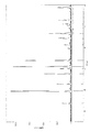
- FIG. 1 is an X-ray diffraction chart of the catalyst obtained in Example 4.
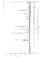
- FIG. 2 is an X-ray diffraction chart after firing of a mixture of the catalyst of Example 4 and aluminum titanate.
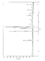
- FIG. 3 is an X-ray diffraction chart of the catalyst obtained in Comparative Example 5.
- FIG. 4 is an X-ray diffraction chart after firing of a mixture of the catalyst of Comparative Example 5 and aluminum titanate.
- FIG. 5 is a schematic diagram showing an exhaust gas purifying apparatus according to an embodiment of the present invention.
- FIG. 6 is a schematic diagram showing a hardness meter.
- FIG. 7 is a schematic perspective view showing a honeycomb structure manufactured in an example according to the present invention.
- the exhaust gas purification catalyst of the present invention is composite oxide particles, and the composite oxide particles include at least one alkali metal, Si, and Zr.
- the exhaust gas purification catalyst of the present invention preferably has an ionic conductivity of 0.5 ⁇ 10 ⁇ 6 mS / cm or more, and is 0.5 ⁇ 10 ⁇ 6 to 10.0 ⁇ 10 ⁇ 6 mS / cm. Is more preferable.
- the ionic conductivity is 0.5 ⁇ 10 ⁇ 6 mS / cm or more, the catalytic activity is increased, and the combustion efficiency of PM can be improved.
- the exhaust gas purifying catalyst of the present invention is preferably a composite oxide particle containing 30 to 60 mol% of alkali metal, 10 to 40 mol% of Zr, and 20 to 60 mol% of Si, 33 to 50 mol% of alkali metal, and Zr 16 to 25 More preferably, the composite oxide particles contain mol% and Si 25 to 51 mol%.
- these mol% values are the metal content ratios excluding oxygen in the composite oxide, and are values when the content ratios of all metals are 100 mol%.
- the composite oxide particles of the preferred embodiment can be represented by the general formula of A 2X Zr X Si Y O 3X + 2Y .
- A represents at least one alkali metal.
- X represents a positive real number satisfying 1 ⁇ X ⁇ 2
- Y represents a positive real number satisfying 1 ⁇ Y ⁇ 6. More preferably, Y is a positive real number that satisfies 1 ⁇ Y ⁇ 3.
- alkali metal examples include Li, Na, K, Rb, Cs, and Fr, and among these, Li, Na, K, and Cs are preferable from the economically advantageous point.
- Examples of the exhaust gas purification catalyst of the present invention include Li 2 ZrSiO 5 , Na 2 ZrSiO 5 , Na 4 Zr 2 Si 3 O 12 , Na 2 ZrSi 2 O 7 , Na 2 ZrSi 3 O 9 , K 2 ZrSiO 5 , K 2.
- Examples include ZrSi 2 O 7 , K 2 ZrSi 3 O 9 , Cs 4 Zr 2 Si 3 O 12 , Cs 2 ZrSi 2 O 7 , Cs 2 ZrSi 3 O 9 and the like.
- the exhaust gas purification catalyst of the present invention can contain other elements as long as the excellent characteristics are not impaired.
- Fe, Nb, Ti, Al, Ce, Ca, Mg, Sr, Ba, Y, Mn, P, etc. can be illustrated.
- the content of other elements is preferably in the range of 0.1 to 30.0 mol%.
- the method for producing the composite oxide particles used in the present invention is not particularly limited.
- the composite oxide particles may be produced by firing a mixture containing at least one alkali metal salt, a silicon source, and a zirconium source. it can.
- the mixing ratio of the alkali metal salt, the zirconium source and the silicon source can be appropriately selected depending on the composition of the target composite oxide particles.
- the alkali metal salt is 20 to 50 mol%
- the zirconium source is 10 to 50 mol%
- the source is preferably 20 to 70 mol%, more preferably 20 to 35 mol% alkali metal salt, 20 to 35 mol% zirconium source, and 30 to 60 mol% silicon source.
- Alkali metal salts include alkali metal carbonates, hydrogen carbonates, organic acid salts such as hydroxides and acetates, sulfates, nitrates, and the like, with carbonates being preferred.
- the silicon source is not particularly limited as long as it is a raw material that contains silicon element and does not inhibit the formation of the composite oxide particles of the present invention by firing.
- silicon element for example, there is a compound that is led to silicon oxide by firing in air.
- examples of such compounds include silicon oxide and silicon, and silicon oxide is preferable.
- the zirconium source is not particularly limited as long as it is a raw material that contains zirconium element and does not inhibit the formation of the composite oxide particles of the present invention by firing.
- zirconium oxide there is a compound that is led to zirconium oxide by firing in air.
- examples of such compounds include zirconium oxide, zirconium carbonate hydrate, zirconium sulfate hydrate and the like, and zirconium oxide is preferable.
- the temperature at which the mixture is fired can be appropriately selected depending on the composition of the target composite oxide particles, but is preferably in the range of 900 to 1300 ° C.
- the time for firing the mixture can be appropriately selected depending on the composition of the target composite oxide particles, but it is preferably 4 to 24 hours.
- the exhaust gas purifying catalyst of the present invention can combust PM contained in exhaust gas discharged from an internal combustion engine or the like at a low temperature due to the high catalytic activity of alkali metal, and further has high ionic conductivity.
- the combustion efficiency is improved.
- Heat resistance can be improved by including Si and Zr in the crystal structure. Further, it is considered that Si and Zr in the crystal structure can suppress elution of alkali metal and prevent deterioration of the carrier.
- the exhaust gas purifying apparatus of the present invention includes the exhaust gas purifying catalyst of the present invention, the PM can be burned at a low temperature, the PM combustion efficiency can be improved, and the heat resistance is high. Yes.
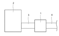
- FIG. 5 is a schematic diagram showing an exhaust gas purifying apparatus according to an embodiment of the present invention.
- the exhaust gas purification device 1 is connected to the exhaust gas generation source 2 via a pipe 3, and the gas discharged from the exhaust gas generation source 2 passes through the pipe 3 and is sent to the exhaust gas purification device 1. After the exhaust gas is purified by the exhaust gas purification device 1, the purified gas is discharged through the pipe 4.
- Examples of the exhaust gas generation source 2 include an internal combustion engine such as a diesel engine or a gasoline engine.
- the carrier of the exhaust gas purification filter is not particularly limited as long as it has a filtration function, and a conventionally known carrier can be used, for example, a honeycomb filter. Specifically, a ceramic wall flow type honeycomb filter is preferably used. As the material, silicon carbide, cordierite, mullite, alumina, aluminum titanate and the like are preferably used. If it is a wall flow type, the number of cells and the wall thickness are not particularly limited.
- the cell wall surface is not particularly limited as long as it is a porous wall, but preferably has pores having a major axis of about 1 ⁇ m to 50 ⁇ m.
- the exhaust gas purification filter of the present invention has a carrier and an exhaust gas purification catalyst carried on the carrier, and the exhaust gas purification catalyst can be used by being carried on the surface of the carrier, cell wall surfaces, pores, and the like. .
- Examples of the method for supporting the exhaust gas purification catalyst on the carrier include an immersion method and a spray method.
- the dipping method prepares a slurry of an exhaust gas purification catalyst together with a binder, a dispersing agent, etc., immerses the carrier in the prepared catalyst slurry, pulls up and dries, and then burns and removes the organic content at 300 ° C. to 800 ° C.
- the catalyst can be supported on a support.
- the carrier particles are mixed with the ceramic particles as the carrier raw material, the exhaust gas purification catalyst of the present invention, a pore-forming agent and the like. It is also possible to carry the mixture on the carrier by calcining it after forming the mixture into the shape.
- the loading amount can be appropriately selected depending on the target filter performance. For example, it can be used in an amount of 1 to 100 parts by mass, preferably 1 to 50 parts by mass, more preferably 1 to 30 parts by mass with respect to 100 parts by mass of the carrier.
- the exhaust gas purifying catalyst of the present invention can burn PM at a low temperature, has high heat resistance, and has low attack on the carrier. Therefore, the exhaust gas purification filter carrying the exhaust gas catalyst of the present invention has high PM combustion efficiency, can suppress catalyst deterioration due to high temperature during abnormal combustion, and has excellent durability and high reliability.
- An exhaust gas purification filter can be obtained.
- the exhaust gas purification filter of the present invention is preferably used for a diesel engine filter (DPF), a gasoline engine filter, and the like for removing PM contained in exhaust gas discharged from an internal combustion engine because of its excellent function. it can.
- Example 2 30.3 parts by mass of sodium carbonate, 35.3 parts by mass of zirconium oxide, and 34.4 parts by mass of silicon oxide were mixed and baked at 1200 ° C. for 4 hours. It was confirmed by X-ray diffraction that the obtained particulate solid was a single phase of Na 2 ZrSi 2 O 7 .
- Example 3 25.9 parts by mass of sodium carbonate, 30.1 parts by mass of zirconium oxide, and 44.0 parts by mass of silicon oxide were mixed and baked at 1200 ° C. for 4 hours. It was confirmed by X-ray diffraction that the obtained particulate solid was a single phase of Na 2 ZrSi 3 O 9 .
- Example 4 Sodium carbonate 33.2 parts by mass, zirconium oxide 38.6 parts by mass, and silicon oxide 28.2 parts by mass were mixed and calcined at 1200 ° C. for 4 hours. It was confirmed by X-ray diffraction that the obtained particulate solid was a single phase of Na 4 Zr 2 Si 3 O 12 .
- Example 5 43.0 parts by mass of potassium carbonate, 38.3 parts by mass of zirconium oxide, and 18.7 parts by mass of silicon oxide were mixed and baked at 1200 ° C. for 4 hours. It was confirmed by X-ray diffraction that the obtained particulate solid was a single phase of K 2 ZrSiO 5 .
- Example 6 36.2 parts by mass of potassium carbonate, 32.3 parts by mass of zirconium oxide, and 31.5 parts by mass of silicon oxide were mixed and baked at 1200 ° C. for 4 hours.
- the obtained particulate solid was confirmed to be a single phase of K 2 ZrSi 2 O 7 by X-ray diffraction.
- Example 7 31.3 parts by mass of potassium carbonate, 27.9 parts by mass of zirconium oxide, and 40.8 parts by mass of silicon oxide were mixed and baked at 1200 ° C. for 4 hours. It was confirmed by X-ray diffraction that the obtained particulate solid was a single phase of K 2 ZrSi 3 O 9 .
- Example 8 51.8 parts by mass of cesium carbonate, 19.6 parts by mass of zirconium oxide, and 28.6 parts by mass of silicon oxide were mixed and baked at 1200 ° C. for 4 hours. It was confirmed by X-ray diffraction that the obtained particulate solid was a single phase of Cs 2 ZrSi 3 O 9 .
- Example 9 28.7 parts by mass of lithium carbonate, 47.9 parts by mass of zirconium oxide, and 23.4 parts by mass of silicon oxide were mixed and fired at 1200 ° C. for 4 hours.
- the obtained particulate solid was confirmed to be a single phase of Li 2 ZrSiO 5 by X-ray diffraction.
- the obtained exhaust gas purification catalyst was pulverized in a mortar, and 5% by mass of carbon black (Tokai Black 7100F, manufactured by Tokai Carbon Co., Ltd.) was added as a pseudo PM and mixed in a mortar.
- carbon black Tokai Black 7100F, manufactured by Tokai Carbon Co., Ltd.
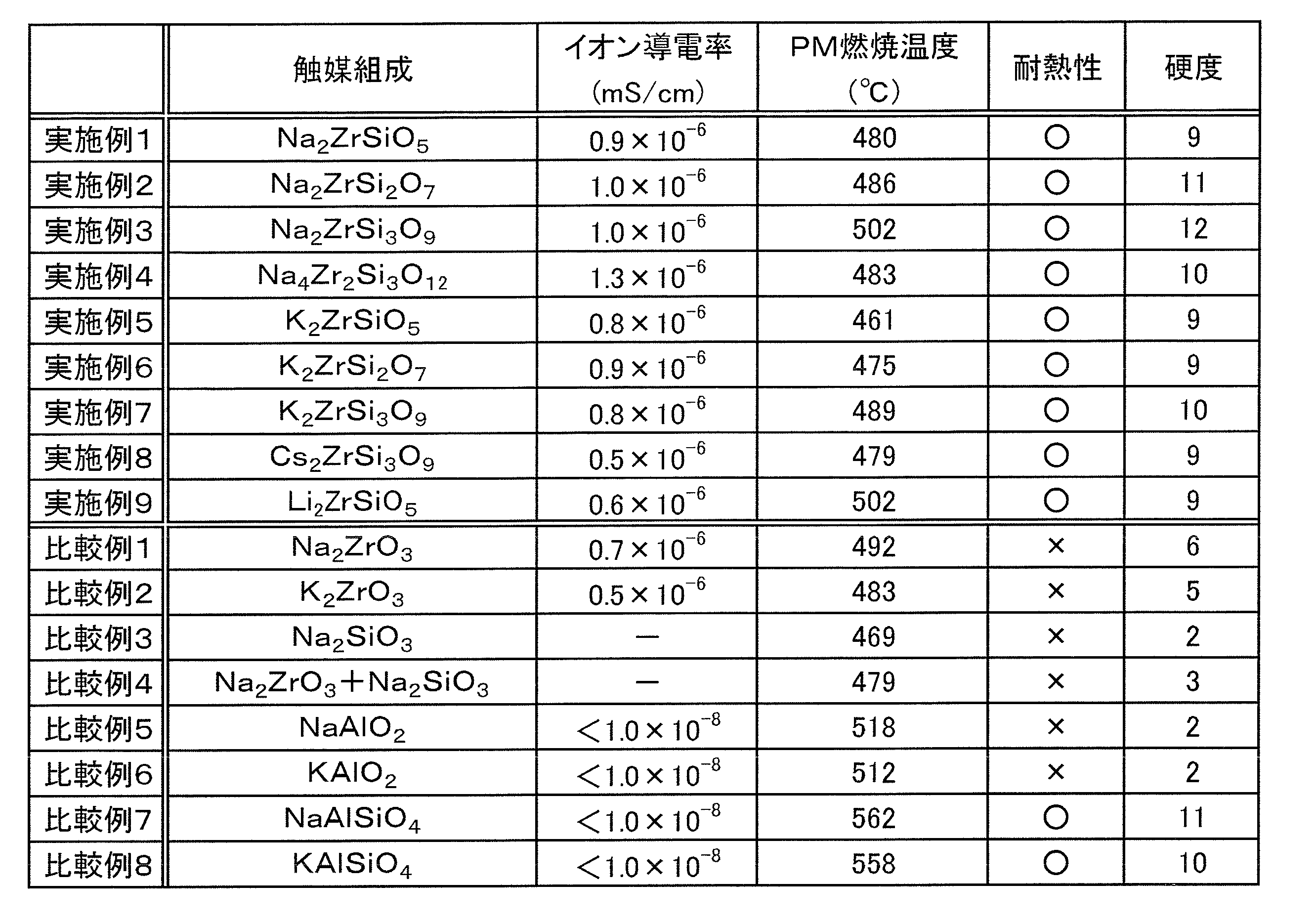
- the obtained mixture was subjected to a temperature analysis using a thermal analyzer (manufactured by Seiko Instruments Inc., EXSTAR6000 TG / DTA6300) under conditions of temperature rise: 10 ° C./min, atmosphere: dry air 200 ml / min, sample amount: 10 mg. DTA measurement was performed to measure the temperature (DTG curve peak temperature) at which the mass reduction rate accompanying the combustion of carbon black was maximized. The results are shown in Table 1.
- FIG. 1 shows an X-ray diffraction chart of the catalyst Na 4 Zr 2 Si 3 O 12 obtained in Example 4.
- FIG. 2 shows an X-ray diffraction chart of the fired product after firing the mixture of the catalyst of Example 4 and aluminum titanate under the above conditions.
- FIG. 3 shows an X-ray diffraction chart of NaAlO 2 obtained in Comparative Example 5.
- FIG. 4 shows an X-ray diffraction chart of the fired product after firing a mixture of NaAlO 2 and aluminum titanate under the above conditions. Show.
- the obtained kneaded material was extruded and molded to form a honeycomb structure with an extrusion molding machine to obtain a molded body.
- the cell density of the mold was 300 cells / square inch (46.5 cells / cm 2 ), and the partition wall thickness was 500 ⁇ m.
- the hardness of the obtained molded body was evaluated using a hardness meter (CLAI HARDNESS TESTER manufactured by NGK Corporation).
- FIG. 6 is a schematic diagram showing the hardness meter used here.
- a spring (not shown) is accommodated in a cylindrical body 7, and a conical needle 6 is provided at the tip of the spring.
- the needle 6 has a height X of 35 mm and a diameter Y of 10 mm.
- the spring constant of the spring accommodated in the cylindrical body 7 is 245 N / mm.
- the cylindrical body 7 is provided with a scale 7a, and the amount of movement of the conical needle 6 can be read by the scale 7a.
- the needle 6 of the hardness meter 5 is inserted into the molded body to a predetermined position, and the load is read from the scale 7a at that time and measured.
- the value of the load reading of the hardness meter 5 is “hardness”.
- the hardness is the yield strength of the material against the needle-shaped indenter, that is, the smaller the resistance value applied to the indenter, the weaker the material.
- the hardness meter 5 was inserted into the flat part of the molded body to the base of the needle 6 in 5 seconds, and the reading value of the hardness meter 5 at this time was recorded (the measured value of the hardness meter 5 is 0 to 20). The results are shown in Table 1.
- Examples 1 to 9 according to the present invention show that the PM combustion temperature is low and the heat resistance is high, and further, since the hardness is large, it is understood that the influence on the molded body is small.
- the obtained kneaded material was extruded and molded to form a honeycomb structure with an extrusion molding machine to obtain a molded body.
- the cell density of the mold was 300 cells / square inch (46.5 cells / cm 2 ), and the partition wall thickness was 300 ⁇ m.
- a slurry was prepared in which the solid content was substantially composed of aluminum titanate (manufactured by Marusu Shinyaku Co., Ltd.) and the exhaust gas purification catalyst obtained in Example 4, and additives such as viscosity modifiers were added.
- the slurry was injected into the cells of the honeycomb structure so that the opened cells and the sealed cells had a checkered pattern alternately, and plugged.
- FIG. 7 is a perspective view showing the obtained exhaust gas purification filter 10.
- arrow A indicates the extrusion direction.
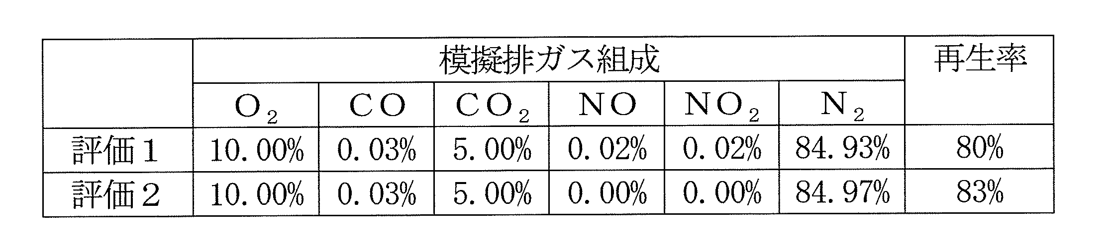
- a regeneration test was performed in the following procedure as an evaluation of the obtained exhaust gas purification filter.
- the initial weight of the exhaust gas purification filter was measured in advance, and an oxidation catalyst (DOC) and an exhaust gas purification filter were sequentially installed in the exhaust line of the diesel engine. After installation, the diesel engine was started, PM was deposited in a predetermined amount (about 8 g / L) under operating conditions where the exhaust temperature was low, the honeycomb sintered body was once removed, and the weight of the deposited PM was measured.
- DOC oxidation catalyst
- an exhaust gas purification filter on which PM was deposited was installed in the exhaust line of the simulated gas.
- Regeneration rate (%) 100 ⁇ [(PM deposition weight (g) ⁇ PM combustion weight (g)) / PM deposition weight (g)] ⁇ 100
- the platinum-based catalyst used in the conventional exhaust gas filter burns and removes PM by utilizing the oxidation ability of NO 2 , but the exhaust gas purification filter according to the present invention has NO 2 presence or absence as shown in Table 2. Regardless, it is possible to burn PM.
Landscapes
- Chemical & Material Sciences (AREA)
- Engineering & Computer Science (AREA)
- Chemical Kinetics & Catalysis (AREA)
- Materials Engineering (AREA)
- Organic Chemistry (AREA)
- Combustion & Propulsion (AREA)
- Health & Medical Sciences (AREA)
- Analytical Chemistry (AREA)
- Biomedical Technology (AREA)
- Environmental & Geological Engineering (AREA)
- General Chemical & Material Sciences (AREA)
- Oil, Petroleum & Natural Gas (AREA)
- Mechanical Engineering (AREA)
- General Engineering & Computer Science (AREA)
- Toxicology (AREA)
- Catalysts (AREA)
- Exhaust Gas Treatment By Means Of Catalyst (AREA)
- Processes For Solid Components From Exhaust (AREA)
Description
(式中、Aは少なくとも1種のアルカリ金属を示し、Xは1≦X≦2を満たす正の実数を示し、Yは1≦Y≦6を満たす正の実数を示す。)
(実施例1)
炭酸ナトリウム36.6質量部、酸化ジルコニウム42.6質量部、及び酸化ケイ素20.8質量部を混合し、1200℃で4時間焼成した。得られた粒子状固体が、X線回折によりNa2ZrSiO5の単相であることを確認した。
炭酸ナトリウム30.3質量部、酸化ジルコニウム35.3質量部、及び酸化ケイ素34.4質量部を混合し、1200℃で4時間焼成した。得られた粒子状固体が、X線回折によりNa2ZrSi2O7の単相であることを確認した。
炭酸ナトリウム25.9質量部、酸化ジルコニウム30.1質量部、及び酸化ケイ素44.0質量部を混合し、1200℃で4時間焼成した。得られた粒子状固体が、X線回折によりNa2ZrSi3O9の単相であることを確認した。
炭酸ナトリウム33.2質量部、酸化ジルコニウム38.6質量部、及び酸化ケイ素28.2質量部を混合し、1200℃で4時間焼成した。得られた粒子状固体が、X線回折によりNa4Zr2Si3O12の単相であることを確認した。
炭酸カリウム43.0質量部、酸化ジルコニウム38.3質量部、及び酸化ケイ素18.7質量部を混合し、1200℃で4時間焼成した。得られた粒子状固体が、X線回折によりK2ZrSiO5の単相であることを確認した。
炭酸カリウム36.2質量部、酸化ジルコニウム32.3質量部、及び酸化ケイ素31.5質量部を混合し、1200℃で4時間焼成した。得られた粒子状固体が、X線回折によりK2ZrSi2O7の単相であることを確認した。
炭酸カリウム31.3質量部、酸化ジルコニウム27.9質量部、及び酸化ケイ素40.8質量部を混合し、1200℃で4時間焼成した。得られた粒子状固体が、X線回折によりK2ZrSi3O9の単相であることを確認した。
炭酸セシウム51.8質量部、酸化ジルコニウム19.6質量部、及び酸化ケイ素28.6質量部を混合し、1200℃で4時間焼成した。得られた粒子状固体が、X線回折によりCs2ZrSi3O9の単相であることを確認した。
炭酸リチウム28.7質量部、酸化ジルコニウム47.9質量部、及び酸化ケイ素23.4質量部を混合し、1200℃で4時間焼成した。得られた粒子状固体が、X線回折によりLi2ZrSiO5の単相であることを確認した。
炭酸ナトリウム46.2質量部、酸化ジルコニウム53.8質量部を混合し、1200℃で4時間焼成した。得られた粒子状固体が、X線回折によりNa2ZrO3の単相であることを確認した。
炭酸カリウム52.9質量部、及び酸化ジルコニウム47.1質量部を混合し、1200℃で4時間焼成した。得られた粒子状固体が、X線回折によりK2ZrO3の単相であることを確認した。
炭酸ナトリウム63.8質量部、及び酸化ケイ素36.2質量部を混合し、1200℃で4時間焼成した。得られた粘性油状物が、X線回折によりNa2SiO3の単相であることを確認した。
比較例1で得たNa2ZrO3と、比較例3で得たNa2SiO3とを、それぞれ50質量%づつ混合し、混合物を得た。
炭酸ナトリウム51.0質量部、及び酸化アルミニウム49.0質量部を混合し、1200℃で4時間焼成した。得られた粒子状固体が、X線回折によりNaAlO2の単相であることを確認した。
炭酸カリウム57.5質量部、及び酸化アルミニウム42.5質量部を混合し、1200℃で4時間焼成した。得られた粒子状固体が、X線回折によりKAlO2の単相であることを確認した。
炭酸ナトリウム32.3質量部、酸化アルミニウム31.1質量部、及び酸化ケイ素36.6質量部を混合し、1200℃で4時間焼成した。得られた粒子状固体が、X線回折によりNaAlSiO4の単相であることを確認した。
炭酸カリウム38.4質量部、酸化アルミニウム28.3質量部、及び酸化ケイ素33.3質量部を混合し、1200℃で4時間焼成した。得られた粒子状固体が、X線回折によりKAlSiO4の単相であることを確認した。
(イオン導電率)
得られた排ガス浄化触媒10gの圧粉体を作製し、1200℃で4時間焼成した。得られた焼結体に導電性ペースト(日本黒鉛社製、バニーハイトT-602)でアルミ箔を圧着し電極を形成し、電極にアルミリード線を圧着して測定サンプルを得た。得られた測定サンプルをインピーダンスアナライザー(Ivium社製、IviumStat)にてイオン導電率を測定し、表1に結果を示した。なお、比較例3が粘性油状物であることから、比較例3及び比較例4は測定に適した測定サンプルを作製することができなかった。
得られた排ガス浄化触媒を乳鉢で粉砕し、疑似PMとしてカーボンブラック(東海カーボン社製、トーカブラック7100F)を5質量%添加し乳鉢混合した。
得られた排ガス浄化触媒10質量部に対しチタン酸アルミニウム(丸ス釉薬社製)90質量部を加えて乳鉢混合した。得られた混合物を1000℃で4時間焼成した。X線回折により、ピークが焼成前と比較して変化が見られないものを「○」、変化したものを「×」とした。結果を表1に示した。
得られた排ガス浄化触媒10質量部に対し、チタン酸アルミニウム(丸ス釉薬社製)90質量部、黒鉛20質量部、メチルセルロース10質量部、及び脂肪酸石鹸0.5質量部を配合し、さらに水を適当量添加して混練し、押出成形可能な坏土を得た。
実施例4で得られた排ガス浄化触媒30質量部に対し、チタン酸アルミニウム(丸ス釉薬社製)70質量部、黒鉛20質量部、メチルセルロース10質量部、及び脂肪酸石鹸0.5質量部を配合し、さらに水を適当量添加して混練し、押出成形可能な坏土を得た。
再生率(%)=100-[(PM堆積重量(g)-PM燃焼重量(g))/PM堆積重量(g)]×100
2…排ガス発生源
3,4…パイプ
5…硬度計
6…円錐状の針
7…筒状体
7a…目盛
10…排ガス浄化フィルタ
A…成形体の押出方向
Claims (8)
- 少なくとも1種のアルカリ金属と、Siと、Zrとを含む複合酸化物粒子であることを特徴とする排ガス浄化触媒。
- イオン導電率が0.5×10⁻⁶mS/cm以上であることを特徴とする請求項1に記載の排ガス浄化触媒。
- 複合酸化物中における酸素を除く各金属の含有割合が、アルカリ金属30~60モル%、Si20~60モル%、Zr10~40モル%である請求項1または2に記載の排ガス浄化触媒。
- 複合酸化物が、以下の一般式で表されることを特徴とする請求項1または2に記載の排ガス浄化触媒。
A2XZrXSiYO3x+2Y
(式中、Aは少なくとも1種のアルカリ金属を示し、Xは1≦X≦2を満たす正の実数を示し、Yは1≦Y≦6を満たす正の実数を示す。) - 請求項1~4のいずれか1項に記載の排ガス浄化触媒を備えることを特徴とする排ガス浄化装置。
- 担体と、前記担体に担持された請求項1~4のいずれか1項に記載の排ガス浄化触媒と、を有することを特徴とする排ガス浄化フィルタ。
- 前記担体が、ハニカムフィルタであることを特徴とする請求項6に記載の排ガス浄化フィルタ。
- 請求項1~4のいずれか1項に記載の排ガス浄化触媒を製造する方法であって、
少なくとも1種のアルカリ金属塩と、ケイ素源と、ジルコニウム源とを含む混合物を焼成して製造することを特徴とする排ガス浄化触媒の製造方法。
Priority Applications (6)
| Application Number | Priority Date | Filing Date | Title |
|---|---|---|---|
| EP13760652.1A EP2826558A4 (en) | 2012-03-12 | 2013-02-28 | EXHAUST GAS CLEANING CATALYST, EMISSION CLEANING DEVICE AND FILTER, AND METHOD OF MANUFACTURING THIS CATALYST |
| JP2014504776A JP5612795B2 (ja) | 2012-03-12 | 2013-02-28 | 排ガス浄化触媒、排ガス浄化装置及びフィルタ、並びに該触媒の製造方法 |
| KR1020147023332A KR101708986B1 (ko) | 2012-03-12 | 2013-02-28 | 배기 가스 정화 촉매, 배기 가스 정화 장치 및 필터, 및 상기 촉매의 제조 방법 |
| CN201380010191.3A CN104379252B (zh) | 2012-03-12 | 2013-02-28 | 排气净化催化剂、排气净化装置、过滤器和该催化剂的制造方法 |
| US14/377,434 US20150056106A1 (en) | 2012-03-12 | 2013-02-28 | Exhaust gas purification catalyst, exhaust gas purification device and filter, and production method for said catalyst |
| US15/478,720 US20170248049A1 (en) | 2012-03-12 | 2017-04-04 | Exhaust gas purification catalyst, exhaust gas purification device and filter, and production method for said catalyst |
Applications Claiming Priority (2)
| Application Number | Priority Date | Filing Date | Title |
|---|---|---|---|
| JP2012-054182 | 2012-03-12 | ||
| JP2012054182 | 2012-03-12 |
Related Child Applications (2)
| Application Number | Title | Priority Date | Filing Date |
|---|---|---|---|
| US14/377,434 A-371-Of-International US20150056106A1 (en) | 2012-03-12 | 2013-02-28 | Exhaust gas purification catalyst, exhaust gas purification device and filter, and production method for said catalyst |
| US15/478,720 Division US20170248049A1 (en) | 2012-03-12 | 2017-04-04 | Exhaust gas purification catalyst, exhaust gas purification device and filter, and production method for said catalyst |
Publications (1)
| Publication Number | Publication Date |
|---|---|
| WO2013136991A1 true WO2013136991A1 (ja) | 2013-09-19 |
Family
ID=49160907
Family Applications (1)
| Application Number | Title | Priority Date | Filing Date |
|---|---|---|---|
| PCT/JP2013/055279 Ceased WO2013136991A1 (ja) | 2012-03-12 | 2013-02-28 | 排ガス浄化触媒、排ガス浄化装置及びフィルタ、並びに該触媒の製造方法 |
Country Status (6)
| Country | Link |
|---|---|
| US (2) | US20150056106A1 (ja) |
| EP (1) | EP2826558A4 (ja) |
| JP (1) | JP5612795B2 (ja) |
| KR (1) | KR101708986B1 (ja) |
| CN (1) | CN104379252B (ja) |
| WO (1) | WO2013136991A1 (ja) |
Cited By (1)
| Publication number | Priority date | Publication date | Assignee | Title |
|---|---|---|---|---|
| KR20170020337A (ko) | 2014-06-19 | 2017-02-22 | 오츠카 가가쿠 가부시키가이샤 | 배기 가스 정화 촉매, 배기 가스 정화 장치 및 필터, 및 해당 촉매의 제조 방법 |
Families Citing this family (2)
| Publication number | Priority date | Publication date | Assignee | Title |
|---|---|---|---|---|
| CN104817315A (zh) * | 2015-04-10 | 2015-08-05 | 中国建筑材料科学研究总院 | 一种锆硅酸钠粉体及其制备方法 |
| US10030556B2 (en) * | 2015-07-15 | 2018-07-24 | University Of Notre Dame Du Lac | Glass catalyst compositions for improved hydrothermal durability |
Citations (3)
| Publication number | Priority date | Publication date | Assignee | Title |
|---|---|---|---|---|
| JPH0985092A (ja) * | 1995-09-22 | 1997-03-31 | Toyota Central Res & Dev Lab Inc | 排ガス浄化用触媒及び排ガス浄化方法 |
| JPH10118490A (ja) | 1996-10-23 | 1998-05-12 | Matsushita Electric Ind Co Ltd | 排ガス浄化触媒及びこれを用いた排ガス浄化フィルタ |
| JP2000202243A (ja) * | 1999-01-13 | 2000-07-25 | Hitachi Ltd | 内燃機関の排ガス浄化方法と浄化触媒および排ガス浄化装置 |
Family Cites Families (6)
| Publication number | Priority date | Publication date | Assignee | Title |
|---|---|---|---|---|
| JP4438114B2 (ja) * | 1999-01-14 | 2010-03-24 | 株式会社日立製作所 | 内燃機関の排ガス浄化方法,排ガス浄化触媒及び排ガス浄化装置 |
| AU7616300A (en) * | 1999-10-05 | 2001-05-10 | Corning Incorporated | Refractory nzp-type structures and method of making and using same |
| JP4050041B2 (ja) * | 2001-11-06 | 2008-02-20 | 株式会社日本触媒 | 酸化エチレン製造用触媒、その製造方法および当該触媒による酸化エチレンの製造方法 |
| JP5054321B2 (ja) * | 2006-03-28 | 2012-10-24 | 日揮触媒化成株式会社 | 歯科用充填材、その製造方法および歯科用複合材料 |
| DE102007034633A1 (de) * | 2007-04-05 | 2009-01-29 | Nano-X Gmbh | Beschichtungsmaterial mit einer katalytischen Aktivität und Verwendung des Beschichtungsmaterials |
| CN100497183C (zh) * | 2007-07-25 | 2009-06-10 | 濮阳濮耐高温材料(集团)股份有限公司 | 一种以锆英石为原料制备氧化锆粉体的方法 |
-
2013
- 2013-02-28 EP EP13760652.1A patent/EP2826558A4/en not_active Withdrawn
- 2013-02-28 WO PCT/JP2013/055279 patent/WO2013136991A1/ja not_active Ceased
- 2013-02-28 KR KR1020147023332A patent/KR101708986B1/ko not_active Expired - Fee Related
- 2013-02-28 JP JP2014504776A patent/JP5612795B2/ja not_active Expired - Fee Related
- 2013-02-28 CN CN201380010191.3A patent/CN104379252B/zh not_active Expired - Fee Related
- 2013-02-28 US US14/377,434 patent/US20150056106A1/en not_active Abandoned
-
2017
- 2017-04-04 US US15/478,720 patent/US20170248049A1/en not_active Abandoned
Patent Citations (3)
| Publication number | Priority date | Publication date | Assignee | Title |
|---|---|---|---|---|
| JPH0985092A (ja) * | 1995-09-22 | 1997-03-31 | Toyota Central Res & Dev Lab Inc | 排ガス浄化用触媒及び排ガス浄化方法 |
| JPH10118490A (ja) | 1996-10-23 | 1998-05-12 | Matsushita Electric Ind Co Ltd | 排ガス浄化触媒及びこれを用いた排ガス浄化フィルタ |
| JP2000202243A (ja) * | 1999-01-13 | 2000-07-25 | Hitachi Ltd | 内燃機関の排ガス浄化方法と浄化触媒および排ガス浄化装置 |
Non-Patent Citations (2)
| Title |
|---|
| G.VITINS ET AL.: "Synthesis and structural and ionic conductivity studies of Na2ZrSi4011", SOLID STATE IONICS, vol. 86-88, no. 1, July 1996 (1996-07-01), pages 119 - 124, XP004070008 * |
| See also references of EP2826558A4 |
Cited By (2)
| Publication number | Priority date | Publication date | Assignee | Title |
|---|---|---|---|---|
| KR20170020337A (ko) | 2014-06-19 | 2017-02-22 | 오츠카 가가쿠 가부시키가이샤 | 배기 가스 정화 촉매, 배기 가스 정화 장치 및 필터, 및 해당 촉매의 제조 방법 |
| US9999872B2 (en) | 2014-06-19 | 2018-06-19 | Otsuka Chemical Co., Ltd. | Exhaust gas purifying catalyst, exhaust gas purification device and filter, and method for producing said catalyst |
Also Published As
| Publication number | Publication date |
|---|---|
| CN104379252B (zh) | 2017-04-19 |
| JP5612795B2 (ja) | 2014-10-22 |
| KR101708986B1 (ko) | 2017-02-21 |
| EP2826558A4 (en) | 2016-01-06 |
| EP2826558A1 (en) | 2015-01-21 |
| JPWO2013136991A1 (ja) | 2015-08-03 |
| US20150056106A1 (en) | 2015-02-26 |
| US20170248049A1 (en) | 2017-08-31 |
| CN104379252A (zh) | 2015-02-25 |
| KR20140120348A (ko) | 2014-10-13 |
Similar Documents
| Publication | Publication Date | Title |
|---|---|---|
| JP5773337B2 (ja) | 酸化触媒及びディーゼルパーティキュレートフィルター | |
| JP5303131B2 (ja) | 炭素系物質燃焼触媒及びその製造方法、触媒担持体及びその製造方法 | |
| JP5864443B2 (ja) | 排気ガス浄化用触媒 | |
| JP6670386B2 (ja) | メタン酸化触媒 | |
| EP2353713A1 (en) | Composite oxide for exhaust-gas purification catalyst, process for producing same, coating material for exhaust-gas purification catalyst, and filter for diesel exhaust-gas purification | |
| WO2012093600A1 (ja) | 排気ガス浄化用触媒及び排気ガス浄化用触媒構成体 | |
| JP4505046B2 (ja) | 排気ガス浄化用触媒及びその製造方法 | |
| JP5303130B2 (ja) | 炭素系物質燃焼触媒及びその製造方法、触媒担持体及びその製造方法 | |
| JP5612795B2 (ja) | 排ガス浄化触媒、排ガス浄化装置及びフィルタ、並びに該触媒の製造方法 | |
| JP2013006170A (ja) | 排気ガス浄化用触媒及び担体 | |
| JP5942550B2 (ja) | 粒子状物質燃焼触媒及びその製造方法 | |
| JP2013052343A (ja) | 触媒 | |
| KR20170020337A (ko) | 배기 가스 정화 촉매, 배기 가스 정화 장치 및 필터, 및 해당 촉매의 제조 방법 | |
| JP5328783B2 (ja) | パティキュレート燃焼触媒、パティキュレートフィルター及び排ガス浄化装置 | |
| JP2016123937A (ja) | 排ガス浄化触媒、排ガス浄化装置及びフィルタ、並びに該触媒の製造方法 | |
| JP4503314B2 (ja) | 排ガス浄化用触媒 | |
| JP2010284597A (ja) | ディーゼル排ガス酸化触媒及びディーゼル排ガス酸化触媒ハニカム構造体 | |
| JP2018051468A (ja) | 排ガス浄化フィルタ | |
| JP6463909B2 (ja) | 排ガス浄化触媒、排ガス浄化装置及びフィルタ、並びに該触媒の製造方法 | |
| JP2019136632A (ja) | 燃焼触媒 | |
| JP2010184183A (ja) | 排ガス浄化装置 | |
| JP6296392B2 (ja) | 燃焼触媒及びそれを用いた排ガス燃焼フィルタ | |
| US20060040824A1 (en) | Nitrogen oxides-removing material and device | |
| JP5444755B2 (ja) | 排ガス浄化用触媒 | |
| JP2016036782A (ja) | 粒子状物質燃焼触媒及び排ガス浄化フィルタ |
Legal Events
| Date | Code | Title | Description |
|---|---|---|---|
| 121 | Ep: the epo has been informed by wipo that ep was designated in this application |
Ref document number: 13760652 Country of ref document: EP Kind code of ref document: A1 |
|
| DPE1 | Request for preliminary examination filed after expiration of 19th month from priority date (pct application filed from 20040101) | ||
| ENP | Entry into the national phase |
Ref document number: 2014504776 Country of ref document: JP Kind code of ref document: A |
|
| WWE | Wipo information: entry into national phase |
Ref document number: 2013760652 Country of ref document: EP |
|
| WWE | Wipo information: entry into national phase |
Ref document number: 14377434 Country of ref document: US |
|
| ENP | Entry into the national phase |
Ref document number: 20147023332 Country of ref document: KR Kind code of ref document: A |
|
| NENP | Non-entry into the national phase |
Ref country code: DE |