WO2013137038A1 - アイドリングストップ制御装置 - Google Patents
アイドリングストップ制御装置 Download PDFInfo
- Publication number
- WO2013137038A1 WO2013137038A1 PCT/JP2013/055792 JP2013055792W WO2013137038A1 WO 2013137038 A1 WO2013137038 A1 WO 2013137038A1 JP 2013055792 W JP2013055792 W JP 2013055792W WO 2013137038 A1 WO2013137038 A1 WO 2013137038A1
- Authority
- WO
- WIPO (PCT)
- Prior art keywords
- engine
- seat belt
- driver
- idling stop
- vehicle door
- Prior art date
- Legal status (The legal status is an assumption and is not a legal conclusion. Google has not performed a legal analysis and makes no representation as to the accuracy of the status listed.)
- Ceased
Links
Images




Classifications
-
- B—PERFORMING OPERATIONS; TRANSPORTING
- B60—VEHICLES IN GENERAL
- B60K—ARRANGEMENT OR MOUNTING OF PROPULSION UNITS OR OF TRANSMISSIONS IN VEHICLES; ARRANGEMENT OR MOUNTING OF PLURAL DIVERSE PRIME-MOVERS IN VEHICLES; AUXILIARY DRIVES FOR VEHICLES; INSTRUMENTATION OR DASHBOARDS FOR VEHICLES; ARRANGEMENTS IN CONNECTION WITH COOLING, AIR INTAKE, GAS EXHAUST OR FUEL SUPPLY OF PROPULSION UNITS IN VEHICLES
- B60K28/00—Safety devices for propulsion-unit control, specially adapted for, or arranged in, vehicles, e.g. preventing fuel supply or ignition in the event of potentially dangerous conditions
- B60K28/02—Safety devices for propulsion-unit control, specially adapted for, or arranged in, vehicles, e.g. preventing fuel supply or ignition in the event of potentially dangerous conditions responsive to conditions relating to the driver
- B60K28/04—Safety devices for propulsion-unit control, specially adapted for, or arranged in, vehicles, e.g. preventing fuel supply or ignition in the event of potentially dangerous conditions responsive to conditions relating to the driver responsive to presence or absence of the driver, e.g. to weight or lack thereof
-
- B—PERFORMING OPERATIONS; TRANSPORTING
- B60—VEHICLES IN GENERAL
- B60K—ARRANGEMENT OR MOUNTING OF PROPULSION UNITS OR OF TRANSMISSIONS IN VEHICLES; ARRANGEMENT OR MOUNTING OF PLURAL DIVERSE PRIME-MOVERS IN VEHICLES; AUXILIARY DRIVES FOR VEHICLES; INSTRUMENTATION OR DASHBOARDS FOR VEHICLES; ARRANGEMENTS IN CONNECTION WITH COOLING, AIR INTAKE, GAS EXHAUST OR FUEL SUPPLY OF PROPULSION UNITS IN VEHICLES
- B60K28/00—Safety devices for propulsion-unit control, specially adapted for, or arranged in, vehicles, e.g. preventing fuel supply or ignition in the event of potentially dangerous conditions
- B60K28/02—Safety devices for propulsion-unit control, specially adapted for, or arranged in, vehicles, e.g. preventing fuel supply or ignition in the event of potentially dangerous conditions responsive to conditions relating to the driver
-
- B—PERFORMING OPERATIONS; TRANSPORTING
- B60—VEHICLES IN GENERAL
- B60K—ARRANGEMENT OR MOUNTING OF PROPULSION UNITS OR OF TRANSMISSIONS IN VEHICLES; ARRANGEMENT OR MOUNTING OF PLURAL DIVERSE PRIME-MOVERS IN VEHICLES; AUXILIARY DRIVES FOR VEHICLES; INSTRUMENTATION OR DASHBOARDS FOR VEHICLES; ARRANGEMENTS IN CONNECTION WITH COOLING, AIR INTAKE, GAS EXHAUST OR FUEL SUPPLY OF PROPULSION UNITS IN VEHICLES
- B60K28/00—Safety devices for propulsion-unit control, specially adapted for, or arranged in, vehicles, e.g. preventing fuel supply or ignition in the event of potentially dangerous conditions
- B60K28/10—Safety devices for propulsion-unit control, specially adapted for, or arranged in, vehicles, e.g. preventing fuel supply or ignition in the event of potentially dangerous conditions responsive to conditions relating to the vehicle
-
- B—PERFORMING OPERATIONS; TRANSPORTING
- B60—VEHICLES IN GENERAL
- B60K—ARRANGEMENT OR MOUNTING OF PROPULSION UNITS OR OF TRANSMISSIONS IN VEHICLES; ARRANGEMENT OR MOUNTING OF PLURAL DIVERSE PRIME-MOVERS IN VEHICLES; AUXILIARY DRIVES FOR VEHICLES; INSTRUMENTATION OR DASHBOARDS FOR VEHICLES; ARRANGEMENTS IN CONNECTION WITH COOLING, AIR INTAKE, GAS EXHAUST OR FUEL SUPPLY OF PROPULSION UNITS IN VEHICLES
- B60K28/00—Safety devices for propulsion-unit control, specially adapted for, or arranged in, vehicles, e.g. preventing fuel supply or ignition in the event of potentially dangerous conditions
- B60K28/10—Safety devices for propulsion-unit control, specially adapted for, or arranged in, vehicles, e.g. preventing fuel supply or ignition in the event of potentially dangerous conditions responsive to conditions relating to the vehicle
- B60K28/12—Safety devices for propulsion-unit control, specially adapted for, or arranged in, vehicles, e.g. preventing fuel supply or ignition in the event of potentially dangerous conditions responsive to conditions relating to the vehicle responsive to conditions relating to doors or doors locks, e.g. open door
-
- B—PERFORMING OPERATIONS; TRANSPORTING
- B60—VEHICLES IN GENERAL
- B60R—VEHICLES, VEHICLE FITTINGS, OR VEHICLE PARTS, NOT OTHERWISE PROVIDED FOR
- B60R22/00—Safety belts or body harnesses in vehicles
- B60R22/48—Control systems, alarms, or interlock systems, for the correct application of the belt or harness
-
- F—MECHANICAL ENGINEERING; LIGHTING; HEATING; WEAPONS; BLASTING
- F02—COMBUSTION ENGINES; HOT-GAS OR COMBUSTION-PRODUCT ENGINE PLANTS
- F02D—CONTROLLING COMBUSTION ENGINES
- F02D17/00—Controlling engines by cutting out individual cylinders; Rendering engines inoperative or idling
- F02D17/04—Controlling engines by cutting out individual cylinders; Rendering engines inoperative or idling rendering engines inoperative or idling, e.g. caused by abnormal conditions
-
- F—MECHANICAL ENGINEERING; LIGHTING; HEATING; WEAPONS; BLASTING
- F02—COMBUSTION ENGINES; HOT-GAS OR COMBUSTION-PRODUCT ENGINE PLANTS
- F02D—CONTROLLING COMBUSTION ENGINES
- F02D29/00—Controlling engines, such controlling being peculiar to the devices driven thereby, the devices being other than parts or accessories essential to engine operation, e.g. controlling of engines by signals external thereto
- F02D29/02—Controlling engines, such controlling being peculiar to the devices driven thereby, the devices being other than parts or accessories essential to engine operation, e.g. controlling of engines by signals external thereto peculiar to engines driving vehicles; peculiar to engines driving variable pitch propellers
-
- F—MECHANICAL ENGINEERING; LIGHTING; HEATING; WEAPONS; BLASTING
- F02—COMBUSTION ENGINES; HOT-GAS OR COMBUSTION-PRODUCT ENGINE PLANTS
- F02N—STARTING OF COMBUSTION ENGINES; STARTING AIDS FOR SUCH ENGINES, NOT OTHERWISE PROVIDED FOR
- F02N11/00—Starting of engines by means of electric motors
- F02N11/08—Circuits specially adapted for starting of engines
- F02N11/0814—Circuits specially adapted for starting of engines comprising means for controlling automatic idle-start-stop
- F02N11/0818—Conditions for starting or stopping the engine or for deactivating the idle-start-stop mode
- F02N11/0822—Conditions for starting or stopping the engine or for deactivating the idle-start-stop mode related to action of the driver
-
- F—MECHANICAL ENGINEERING; LIGHTING; HEATING; WEAPONS; BLASTING
- F02—COMBUSTION ENGINES; HOT-GAS OR COMBUSTION-PRODUCT ENGINE PLANTS
- F02N—STARTING OF COMBUSTION ENGINES; STARTING AIDS FOR SUCH ENGINES, NOT OTHERWISE PROVIDED FOR
- F02N11/00—Starting of engines by means of electric motors
- F02N11/08—Circuits specially adapted for starting of engines
- F02N11/0814—Circuits specially adapted for starting of engines comprising means for controlling automatic idle-start-stop
- F02N11/0818—Conditions for starting or stopping the engine or for deactivating the idle-start-stop mode
- F02N11/0833—Vehicle conditions
-
- B—PERFORMING OPERATIONS; TRANSPORTING
- B60—VEHICLES IN GENERAL
- B60K—ARRANGEMENT OR MOUNTING OF PROPULSION UNITS OR OF TRANSMISSIONS IN VEHICLES; ARRANGEMENT OR MOUNTING OF PLURAL DIVERSE PRIME-MOVERS IN VEHICLES; AUXILIARY DRIVES FOR VEHICLES; INSTRUMENTATION OR DASHBOARDS FOR VEHICLES; ARRANGEMENTS IN CONNECTION WITH COOLING, AIR INTAKE, GAS EXHAUST OR FUEL SUPPLY OF PROPULSION UNITS IN VEHICLES
- B60K28/00—Safety devices for propulsion-unit control, specially adapted for, or arranged in, vehicles, e.g. preventing fuel supply or ignition in the event of potentially dangerous conditions
- B60K2028/003—Safety devices for propulsion-unit control, specially adapted for, or arranged in, vehicles, e.g. preventing fuel supply or ignition in the event of potentially dangerous conditions inhibiting the starter motor, e.g. by controlling ignition or park lock circuits
-
- B—PERFORMING OPERATIONS; TRANSPORTING
- B60—VEHICLES IN GENERAL
- B60R—VEHICLES, VEHICLE FITTINGS, OR VEHICLE PARTS, NOT OTHERWISE PROVIDED FOR
- B60R22/00—Safety belts or body harnesses in vehicles
- B60R22/48—Control systems, alarms, or interlock systems, for the correct application of the belt or harness
- B60R2022/4883—Interlock systems
- B60R2022/4891—Interlock systems preventing use of the vehicle when the seatbelt is not fastened
-
- F—MECHANICAL ENGINEERING; LIGHTING; HEATING; WEAPONS; BLASTING
- F02—COMBUSTION ENGINES; HOT-GAS OR COMBUSTION-PRODUCT ENGINE PLANTS
- F02N—STARTING OF COMBUSTION ENGINES; STARTING AIDS FOR SUCH ENGINES, NOT OTHERWISE PROVIDED FOR
- F02N11/00—Starting of engines by means of electric motors
- F02N11/08—Circuits specially adapted for starting of engines
- F02N11/0814—Circuits specially adapted for starting of engines comprising means for controlling automatic idle-start-stop
- F02N11/0818—Conditions for starting or stopping the engine or for deactivating the idle-start-stop mode
- F02N11/0833—Vehicle conditions
- F02N11/084—State of vehicle accessories, e.g. air condition or power steering
-
- F—MECHANICAL ENGINEERING; LIGHTING; HEATING; WEAPONS; BLASTING
- F02—COMBUSTION ENGINES; HOT-GAS OR COMBUSTION-PRODUCT ENGINE PLANTS
- F02N—STARTING OF COMBUSTION ENGINES; STARTING AIDS FOR SUCH ENGINES, NOT OTHERWISE PROVIDED FOR
- F02N2200/00—Parameters used for control of starting apparatus
- F02N2200/04—Parameters used for control of starting apparatus said parameters being related to the starter motor
- F02N2200/044—Starter current
-
- F—MECHANICAL ENGINEERING; LIGHTING; HEATING; WEAPONS; BLASTING
- F02—COMBUSTION ENGINES; HOT-GAS OR COMBUSTION-PRODUCT ENGINE PLANTS
- F02N—STARTING OF COMBUSTION ENGINES; STARTING AIDS FOR SUCH ENGINES, NOT OTHERWISE PROVIDED FOR
- F02N2200/00—Parameters used for control of starting apparatus
- F02N2200/08—Parameters used for control of starting apparatus said parameters being related to the vehicle or its components
- F02N2200/0806—Air condition state
-
- F—MECHANICAL ENGINEERING; LIGHTING; HEATING; WEAPONS; BLASTING
- F02—COMBUSTION ENGINES; HOT-GAS OR COMBUSTION-PRODUCT ENGINE PLANTS
- F02N—STARTING OF COMBUSTION ENGINES; STARTING AIDS FOR SUCH ENGINES, NOT OTHERWISE PROVIDED FOR
- F02N2200/00—Parameters used for control of starting apparatus
- F02N2200/08—Parameters used for control of starting apparatus said parameters being related to the vehicle or its components
- F02N2200/0815—Vehicle door sensors
-
- F—MECHANICAL ENGINEERING; LIGHTING; HEATING; WEAPONS; BLASTING
- F02—COMBUSTION ENGINES; HOT-GAS OR COMBUSTION-PRODUCT ENGINE PLANTS
- F02N—STARTING OF COMBUSTION ENGINES; STARTING AIDS FOR SUCH ENGINES, NOT OTHERWISE PROVIDED FOR
- F02N2200/00—Parameters used for control of starting apparatus
- F02N2200/10—Parameters used for control of starting apparatus said parameters being related to driver demands or status
- F02N2200/102—Brake pedal position
-
- F—MECHANICAL ENGINEERING; LIGHTING; HEATING; WEAPONS; BLASTING
- F02—COMBUSTION ENGINES; HOT-GAS OR COMBUSTION-PRODUCT ENGINE PLANTS
- F02N—STARTING OF COMBUSTION ENGINES; STARTING AIDS FOR SUCH ENGINES, NOT OTHERWISE PROVIDED FOR
- F02N2200/00—Parameters used for control of starting apparatus
- F02N2200/10—Parameters used for control of starting apparatus said parameters being related to driver demands or status
- F02N2200/103—Clutch pedal position
-
- F—MECHANICAL ENGINEERING; LIGHTING; HEATING; WEAPONS; BLASTING
- F02—COMBUSTION ENGINES; HOT-GAS OR COMBUSTION-PRODUCT ENGINE PLANTS
- F02N—STARTING OF COMBUSTION ENGINES; STARTING AIDS FOR SUCH ENGINES, NOT OTHERWISE PROVIDED FOR
- F02N2200/00—Parameters used for control of starting apparatus
- F02N2200/10—Parameters used for control of starting apparatus said parameters being related to driver demands or status
- F02N2200/106—Driver presence, e.g. detected by door lock, seat sensor or belt sensor
-
- Y—GENERAL TAGGING OF NEW TECHNOLOGICAL DEVELOPMENTS; GENERAL TAGGING OF CROSS-SECTIONAL TECHNOLOGIES SPANNING OVER SEVERAL SECTIONS OF THE IPC; TECHNICAL SUBJECTS COVERED BY FORMER USPC CROSS-REFERENCE ART COLLECTIONS [XRACs] AND DIGESTS
- Y02—TECHNOLOGIES OR APPLICATIONS FOR MITIGATION OR ADAPTATION AGAINST CLIMATE CHANGE
- Y02T—CLIMATE CHANGE MITIGATION TECHNOLOGIES RELATED TO TRANSPORTATION
- Y02T10/00—Road transport of goods or passengers
- Y02T10/10—Internal combustion engine [ICE] based vehicles
- Y02T10/40—Engine management systems
Definitions
- the present invention relates to an idling stop control device.
- the conventional control method has a problem that the idling stop control of the corner does not function effectively because the engine is driven when the vehicle door is opened.
- the vehicle gets off when the vehicle door is opened, and the idling stop control may be stopped (transition to a forced engine stall state) so that automatic return from idling stop (engine restart) is not performed.
- the automatic return is not performed and it is inconvenient that it is necessary to start each time by key operation.
- the problem to be solved by the present invention is to provide an idling stop control device capable of functioning idling stop control more effectively.
- the present invention can be used when the engine restart condition is satisfied when the vehicle door is open and the driver's seat belt is attached, or when the vehicle door is closed and the driver's seat belt is not attached. While the start is permitted, when the vehicle door is open and the driver's seat belt is not attached, the above problem is prevented by prohibiting the engine restart even when the engine restart condition is satisfied. To solve.
- the vehicle door When the vehicle door is open and the driver's seat belt is attached, or when the vehicle door is closed and the driver's seat belt is not attached, it is determined that the operation is temporary or temporary rather than the driver getting off. On the other hand, when the vehicle door is open and the driver's seat belt is not attached, it can be determined that the driver is getting off. For this reason, in the present invention, the engine restart is permitted in the former case, and the engine restart is prohibited in the latter case. Therefore, the vehicle door is temporarily opened or closed and the driver's seat belt is removed. However, the idling stop state is maintained. As a result, the idling stop control can function more effectively.
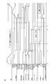
- FIG. 1 is a control time chart of the idling stop system in FIG. 1 (first case: a case where the engine is restarted when the seat belt is detached after the engine is stopped and the clutch is depressed, the solid line is an example, and the dotted line is a comparative example) is there.
- Control time chart of the idling stop system of FIG. 1 (second case: when a predetermined time elapses after the seat belt is detached and the clutch is depressed while the engine is stopped, the engine is prohibited from being restarted, the solid line Examples and dotted lines are comparative examples).
- Control time chart of the idling stop system of FIG. 1 (third case: when the seat belt is removed and the vehicle door is opened while the engine is stopped, the engine is prohibited from being restarted, the solid line is an example, the dotted line is Comparative example).
- FIG. 1 is a control time chart of the idling stop system (fourth case: when the engine is stopped and the seat belt is detached, the engine restart is prohibited unless the clutch is depressed even if the system requests restart.
- Solid lines are examples, and dotted lines are comparative examples).
- FIG. 1 is a block diagram showing an idling stop system 1 to which an idling stop control device according to an embodiment of the present invention is applied.
- the idling stop control device according to the present invention is an internal combustion engine 21 (hereinafter also referred to as engine 21). This can be applied to vehicles including hybrid vehicles. In the following, a vehicle equipped with a manual transmission MT will be described, but the present invention can also be applied to a vehicle equipped with an automatic transmission.
- the engine 21 is controlled by an engine control module 11 (hereinafter sometimes abbreviated as ECM11).
- ECM11 engine control module 11
- the starter motor 22 is driven via the ECM11.
- the starter motor 22 and other in-vehicle electrical equipment are operated by electric power from the battery 23.
- the current flowing through the battery 23 is detected by a current sensor 24 (which may be a voltage sensor), and based on this, the remaining electric power of the battery 23 is calculated by an electronic control unit 25 (hereinafter sometimes abbreviated as ECUD25).
- the ECU D25 outputs a request command for restarting the engine 21 even when idling is stopped when the remaining amount of the battery 23 becomes a predetermined value or less in a normal idling stop state to be described later.
- the electronic control unit 28 (hereinafter sometimes abbreviated as ECUA28) controls the compressor 29 included in the cooling cycle of the air conditioner, and turns on and off the clutch of the compressor 29.
- ECUA28 controls the compressor 29 included in the cooling cycle of the air conditioner, and turns on and off the clutch of the compressor 29.
- the compressor 29 When the evaporator temperature rises above a predetermined value, the compressor 29 must be driven to lower the air conditioning temperature. For this reason, in such a state, a restart request command for the engine 21 is output to the ECM 11.
- the idling stop control device of this example includes an ECM 11, a driver seat belt switch 12, a vehicle door switch 13, a first clutch switch 14, a second clutch switch 15, a neutral switch 16, a notification lamp 18, Is provided.
- the driver's seat belt switch 12 detects the attachment / detachment of the seat belt provided in the driver's seat, and sends a detection signal indicating whether the seat belt is in the mounted state or in the non-mounted state to the electronic control unit 26 (hereinafter, referred to as the seat belt switch). Output to ECUB26).
- the ECU B 26 outputs this detection signal to the ECM 11 via the CAN communication network 28.
- the attachment / detachment state of the seat belt can be detected by, for example, a sensor provided in the fastener portion of the seat belt.
- the vehicle door switch 13 is not limited, in this example, the open / close state of the vehicle door on the driver's seat side is detected, and a detection signal indicating whether the vehicle door is in the open state or the closed state is sent to the electronic control unit 27.
- a detection signal indicating whether the vehicle door is in the open state or the closed state is sent to the electronic control unit 27.
- ECUC27 a detection signal indicating whether the vehicle door is in the open state or the closed state.
- the ECUC 27 outputs a vehicle door detection signal to the ECM 11 via the CAN communication network 28.
- the open / closed state of the vehicle door can be detected by, for example, a sensor provided at the door opening of the vehicle body.
- the first clutch switch 14 detects the depression state of the clutch pedal, and outputs a detection signal to the ECM 11 as to whether the clutch pedal is being depressed shallowly or not.
- the second clutch switch 15 similarly detects the depression state of the clutch pedal, but outputs a detection signal to the ECM 11 as to whether the clutch pedal is depressed deeply or not.
- Both the first clutch switch 14 and the second clutch switch 15 can be constituted by sensors provided in the clutch pedal mechanism.
- the first clutch switch is a high-side clutch switch
- the second clutch switch 15 is a low-side clutch. Also called a switch.
- the first clutch switch 14 detects at a position where the clutch pedal is high (a position where the clutch pedal is shallow and the clutch is not completely disengaged), whereas the second clutch switch 15 detects a position where the clutch pedal is low ( This is because the detection is performed at a position where the clutch pedal is deeply depressed and the clutch is completely disengaged.
- the first clutch switch 14 is a switch that is provided when the operation of depressing the clutch pedal is set to a restart condition when the engine 21 is restarted from the idling stop state, and the shift lever is depressed by depressing the clutch pedal from the neutral position. This is because the engine 21 is restarted with the operation of putting the engine in the first speed or the like as a trigger. Therefore, at the time of restart, the determination is made based on a combination of the detection signal of the first clutch switch 14 and the neutral position signal of the shift lever. At this time, the second clutch switch 15 can be used. However, when the first clutch switch 14 is used for detection at a shallow position, there is an advantage that the time until the engine 21 is restarted is shortened.
- the second clutch switch 15 is also a switch that is provided because the operation of depressing the clutch pedal is made a restart condition when the engine 21 is restarted from the idling stop state.
- the shift lever is not put in the neutral state, but is put in another stage and the state where the clutch pedal is depressed is waited.
- the notification lamp 18 is a first display in which the restart of the engine 21 is permitted by the depression of the clutch pedal in the idling stop state, and the restart of the engine 21 is not permitted by the depression of the clutch pedal in the idling stop state. Then, the second display that requires restart by the ignition key switch 17 is performed.
- the notification lamp 18 can be constituted by, for example, an LED lamp, and the first display is lit in green and the second display is lit in red, respectively, to alert the driver accordingly.
- FIG. 2 shows the control contents when the vehicle door is opened and closed or the driver's seat belt is detached during idling stop when the idling stop condition is satisfied and the engine 21 enters the idling stop state.
- the idling stop condition is a condition for temporarily stopping the running engine. For example, when the engine speed is equal to or lower than a predetermined value, the shift position is neutral, and the clutch pedal is released (or this) The idling stop condition is met when the foot brake is depressed).
- step S21 it is determined whether or not the engine 21 is idling stopped. If the engine 21 is idling stopped, the process proceeds to step S22. If not, the process is terminated.
- step S22 the open / closed state of the vehicle door is detected by the vehicle door switch 13, and if the vehicle door is closed, the process proceeds to step S23, and if it is open, the process proceeds to step S25.
- step S23 the wearing state of the driver's seat belt is detected by the driver's seat belt switch 12. If the driver's seat belt is worn, the process proceeds to step S24, and if not, the process proceeds to step S25.
- FIG. 4 is a control time chart of the idling stop system 1 of this example, and this state corresponds to time t0 to t2 in the same figure. That is, the clutch pedal is depressed immediately before time t1, the shift position is switched to neutral, the clutch pedal is released, and the engine speed is equal to or lower than the predetermined value at time t1, so the idling stop condition is satisfied, and the time At t1, the engine shifts to normal idling stop control, and the engine 21 stops at time t2. In addition, at time t1 when the idle stop condition is satisfied, the notification lamp 18 is lit in green to remind that the engine 21 can be restarted by depressing the clutch pedal. This state is maintained when the vehicle door is closed and the driver's seat belt is attached.
- step S25 transition to the temporary idling stop state occurs when the vehicle door is open or at least one of the case where the driver's seat belt is not attached.
- step S26 it is determined whether the vehicle door is open and the driver's seat belt is not attached. If the vehicle door is open and the driver's seat belt is not attached, step S29 is executed. To go to the forced engine stall state. If the vehicle door is open and the driver's seat belt is not attached, that is, if only one is established, the process proceeds to step S27, where the timer is counted up to determine whether a predetermined time has elapsed. If the predetermined time has not elapsed, the process proceeds to step S28, the temporary idling stop state is continued, and the process proceeds to the next routine.
- either the case where the vehicle door is open or the case where the driver's seat belt is not attached is, for example, a toll gate on a toll road If you temporarily remove the driver's seat belt to pay the toll, or if you temporarily remove the driver's seat belt to take the back seat luggage, or for some reason temporarily or temporarily
- the idling stop control is not canceled immediately and the engine 21 is not forcedly stalled, but the subsequent state is viewed for a predetermined time. It is said.
- This state corresponds to time t3 to t5 in the control time chart of FIG. That is, since the driver's seat belt is removed at time t3 during idling stop, the idling stop state (I / S state in the figure) transitions to the temporary idling stop state, but time t4 before the predetermined time elapses. At time t5, the driver seat belt is mounted again, and the engine 21 is restarted by depressing the clutch pedal at time t5.
- the clutch pedal which is one of the vehicle start operations, The engine 21 can be restarted by the stepping operation, and the trouble of turning on the ignition key switch 17 can be saved.
- step S27 when the predetermined time has elapsed in step S27, it is no longer possible to determine a temporary or temporary operation such as payment of a fee, and thus the process proceeds to step S29 to shift to the forced engine stall state.
- This forced engine stall state is a state in which the engine 21 cannot be restarted by an idling stop canceling operation such as depression of a clutch pedal, and the engine 21 is restarted only when the ignition key switch 17 is turned on.
- FIG. 5 is another control time chart of the idling stop system 1 of this example, and this state corresponds to time t3 to t5 in the same figure. That is, since the driver's seat belt was removed at time t3 during idling stop, the idling stop state (I / S state in the figure) transitioned to the temporary idling stop state, but at time t5, the driver seat belt was mounted again. Since the predetermined time has elapsed before the time t4, the idling stop state is set to the forced engine stall state from the provisional idling stop state up to that time t4.
- step S26 when the vehicle door is open and the driver's seat belt is not attached in step S26, it is highly possible that the operation is a temporary getting-off operation rather than a temporary operation. Transition from the temporary idling stop state to the forced engine stall state. Thereby, even if the restart condition of the engine 21 is satisfied, the engine 21 is not restarted unless the ignition key switch 17 is turned on.
- FIG. 6 is another control time chart of the idling stop system 1 of this example, and this state corresponds to time t3 to t6 in the same figure. That is, since the driver's seat belt was removed at time t3 during idling stop, the idling stop state (I / S state in the figure) transitioned to the temporary idling stop state, but the vehicle door also opened at time t4. Therefore, at the time t4, a transition is made from the temporary idling stop state to the forced engine stall state. Even if the clutch pedal, which is a restart operation, is depressed at time t5, restart is prohibited in the forced engine stall state, and the engine 21 is restarted only after the ignition key switch is turned on at time t6.
- the clutch pedal which is a restart operation
- FIG. 3 is a flowchart showing a control procedure when a restart request signal is input during idling stop.
- the ECM 11 reads a restart request from the ECU D25 or the like, for example, to restart the engine 21 because the capacity of the battery 23 has decreased.
- step S32 it is determined whether or not the idling stop state is a normal idling stop state, that is, a normal idling stop state, another temporary idling stop state, or a forced engine stall state. In the case of a normal idling stop state, the process proceeds to step S33, and a general restart sequence is executed. For example, the starter motor 22 is driven to crank the engine 21 and restart.
- step S34 determines whether or not it is in the temporary idling stop state, that is, in the temporary idling stop state or the forced engine stall state.
- the restart of the engine 21 is prohibited except for the restart by the ignition key switch 17 (see time t4 to t6 in FIG. 6).
- step S35 it is determined whether or not the second clutch switch 15 or the neutral switch 16 is ON and the first clutch switch 14 is ON. If the condition is satisfied, the process proceeds to step S33 to execute the restart sequence. On the other hand, if neither is satisfied, the process proceeds to step S36, and even if there is a restart request from the ECU D25, restart of the engine 21 is prohibited unless the depression condition of the clutch pedal is satisfied.
- FIG. 7 is another control time chart of the idling stop system 1 of this example, and this state corresponds to time t3 to t5 in the same figure. That is, since the driver's seat belt is removed at time t3 during idling stop, the idling stop state (I / S state in the figure) transitions to the temporary idling stop state. At time t4 in this state, the battery 23 Even if a restart request for the engine 21 is input due to factors such as power shortage, the engine 21 is not restarted unless the clutch pedal is depressed at time t5.
- the idling stop control device of this example has the following effects. (1) According to the idling stop control device of this example, the idling stop state is maintained even if the vehicle door is temporarily opened or closed or the driver's seat belt is removed, and as a result, the idling stop control is performed. It can function more effectively. In such a state, the engine does not transition to the forced engine stall, so that it is not necessary to start the engine by a key operation, and the troublesomeness is eliminated.
- the engine 21 is restarted when a predetermined time elapses when it is temporarily or tentatively determined whether to open or close the vehicle door or remove the driver seat belt. Since it prohibits and changes to a forced engine stall, discharge of the battery 23 in the state which the engine 21 stopped can be suppressed.
- the notification lamp 18 displays that the restart of the engine is permitted and prohibited, so that the driver can accurately grasp the current state. it can.
- the driver seat belt switch 12 corresponds to seat belt wearing detection means according to the present invention
- the vehicle door switch 13 corresponds to door opening / closing detection means according to the present invention
- the engine control module 11 is controlled according to the present invention.
- the notification lamp 18 corresponds to display means according to the present invention.
Landscapes
- Engineering & Computer Science (AREA)
- Mechanical Engineering (AREA)
- Chemical & Material Sciences (AREA)
- Combustion & Propulsion (AREA)
- Transportation (AREA)
- General Engineering & Computer Science (AREA)
- Automation & Control Theory (AREA)
- Control Of Vehicle Engines Or Engines For Specific Uses (AREA)
- Output Control And Ontrol Of Special Type Engine (AREA)
- Automotive Seat Belt Assembly (AREA)
- Auxiliary Drives, Propulsion Controls, And Safety Devices (AREA)
Abstract
運転席シートベルトの装着状態及び非装着状態を検出するシートベルト装着検出手段(12)と、車両ドアの開状態及び閉状態を検出するドア開閉検出手段(13)と、アイドリングストップ制御によりエンジン(21)が停止状態にある場合に、所定の再始動条件を満たしたときは前記エンジンを再始動する制御手段(11)と、を備え、前記車両ドアが開状態で前記運転席シートベルトが装着状態の場合又は前記車両ドアが閉状態で前記運転席シートベルトが非装着状態の場合に、前記所定の再始動条件を満たしたときは前記エンジンの再始動を許可し、前記車両ドアが開状態で前記運転席シートベルトが非装着状態の場合に、前記所定の再始動条件を満たしても前記エンジンの再始動を禁止する。
Description
本発明は、アイドリングストップ制御装置に関するものである。
車両のアイドリングストップ制御装置において、車両ドアが開いている場合はアイドリングストップの実行を中止し(エンジン駆動継続)、アイドリングストップを実行中に車両ドアが開いた場合は直ちにアイドリングストップの実行を解除する(エンジン再始動)ことにより、乗降中におけるエンジンの再始動を回避しつつ、エンジン停止にともなうバッテリ消費などの不都合を回避するものが知られている(特許文献1)。
しかしながら、上記従来の制御方法では車両ドアが開くとエンジンが駆動状態になるので、折角のアイドリングストップ制御が有効に機能しないという問題がある。また、車両ドアが開いたところで降車するものとみなし、アイドリングストップからの自動復帰(エンジン再始動)が行なわれない様にアイドリングストップ制御を中止する(強制エンジンストール状態に遷移させる)場合もあるが、実際には降車しないにも関わらず自動復帰が行なわれなくなって、いちいちキー操作による始動が必要になって不便である。
本発明が解決しようとする課題は、アイドリングストップ制御をより有効に機能させ得るアイドリングストップ制御装置を提供することである。
本発明は、車両ドアが開状態で運転席シートベルトが装着状態の場合又は車両ドアが閉状態で運転席シートベルトが非装着状態の場合にエンジンの再始動条件を満たしたときはエンジンの再始動を許可する一方で、車両ドアが開状態で運転席シートベルトが非装着状態の場合には、エンジンの再始動条件を満たした場合であってもエンジンの再始動を禁止することによって上記課題を解決する。
車両ドアが開状態で運転席シートベルトが装着状態又は車両ドアが閉状態で運転席シートベルトが非装着状態の場合は、運転者の降車というよりむしろ一時的乃至暫定的な動作と判断することができ、これに対して車両ドアが開状態で運転席シートベルトが非装着状態の場合は運転者の降車状態と判断することができる。このため本発明では、前者の場合はエンジンの再始動を許可し、後者の場合はエンジンの再始動を禁止するので、一時的乃至暫定的に車両ドアの開閉や運転席シートベルトの取り外しを行ってもアイドリングストップ状態は維持される。その結果、アイドリングストップ制御をより有効に機能させることができる。
以下、本発明の一実施の形態を図面に基づいて説明する。図1は本発明の一実施の形態に係るアイドリングストップ制御装置を適用したアイドリングストップシステム1を示すブロック図であり、本発明に係るアイドリングストップ制御装置は内燃機関21(以下、エンジン21とも言う)を搭載する、ハイブリッド車両を含む車両に適用することができる。以下においては、マニュアルトランスミッションMTを搭載した車両について説明するが、オートマティックトランスミッションを搭載した車両にも適用することができる。
エンジン21は、エンジンコントロールモジュール11(以下、ECM11と略すこともある)により制御され、運転者がイグニッションキースイッチ17をONすると、ECM11を介してスタータモータ22が駆動し、これによりエンジン21がクランキングを経て始動する。スタータモータ22やその他車載電装機器はバッテリ23からの電力で作動する。バッテリ23に流れる電流は電流センサ24(電圧センサでもよい)により検出され、これに基づいてエレクトロニックコントロールユニット25(以下、ECUD25と略すこともある)にてバッテリ23の電力残量が演算される。このECUD25は、後述する通常のアイドリングストップ状態においてバッテリ23の残量が所定値以下になると、アイドリングストップ中であってもエンジン21を再始動させるための要求指令を出力する。なお、エレクトロニックコントロールユニット28(以下、ECUA28と略すこともある)は、空気調和装置の冷房サイクルに含まれるコンプレッサ29を制御するものであり、コンプレッサ29のクラッチを入切するが、空気調和装置のエバポレータの温度が所定値より上昇するとコンプレッサ29を駆動して空調温度を低下する必要がある。このため、このような状態になるとECM11に対してエンジン21の再始動の要求指令を出力する。
本例のアイドリングストップ制御装置は、ECM11と、運転席シートベルトスイッチ12と、車両ドアスイッチ13と、第1クラッチスイッチ14と、第2クラッチスイッチ15と、ニュートラルスイッチ16と、告知ランプ18と、を備える。
運転席シートベルトスイッチ12は、運転席に設けられたシートベルトの着脱を検知し、当該シートベルトが装着状態にあるか、非装着状態にあるかの検出信号を、エレクトロニックコントロールユニット26(以下、ECUB26と略すこともある)に出力する。ECUB26は、この検出信号を、CAN通信網28を介してECM11に出力する。シートベルトの着脱状態は、たとえばシートベルトのファスナー部に設けられたセンサにて検出することができる。
車両ドアスイッチ13は、限定はされないが、本例では運転席側の車両ドアの開閉状態を検知し、当該車両ドアが開状態にあるか、閉状態にあるかの検出信号をエレクトロニックコントロールユニット27(以下、ECUC27と略すこともある)に出力する。必要に応じて運転席側の車両ドア以外の車両ドアに適用してもよい。ECUC27は、車両ドアの検出信号を、CAN通信網28を介してECM11に出力する。車両ドアの開閉状態は、たとえば車体のドア開口部に設けられたセンサにて検出することができる。
第1クラッチスイッチ14は、クラッチペダルの踏込み状態を検知し、当該クラッチペダルが浅く踏まれている状態か、踏まれていない状態かの検出信号をECM11に出力する。これに対して、第2クラッチスイッチ15は、同じくクラッチペダルの踏込み状態を検知するが、当該クラッチペダルが深く踏まれているか、そうでないかの検出信号をECM11に出力する。これら第1クラッチスイッチ14と第2クラッチスイッチ15は、ともにクラッチペダル機構に設けられたセンサにて構成することができ、第1クラッチスイッチをHigh側クラッチスイッチ、第2クラッチスイッチ15をLow側クラッチスイッチともいう。第1クラッチスイッチ14は、クラッチペダルが高い位置(クラッチペダルの踏込みが浅い位置であってクラッチが完全に切れない位置)で検知するのに対し、第2クラッチスイッチ15はクラッチペダルが低い位置(クラッチペダルの踏込みが深い位置であってクラッチが完全に切れる位置)で検知するからである。
なお、第1クラッチスイッチ14は、アイドリングストップ状態からエンジン21を再始動する際にクラッチペダルの踏込み操作を再始動条件にしたために設けられたスイッチであり、ニュートラルポジションからクラッチペダルを踏込んでシフトレバーを第1速等に入れる操作をトリガにしてエンジン21を再始動するためである。したがって、再始動の際は第1クラッチスイッチ14の検出信号とシフトレバーのニュートラル位置信号とを組み合わせた条件にて判断する。このとき第2クラッチスイッチ15を用いることもできるが、第1クラッチスイッチ14を用いて浅い位置で検知した方がエンジン21の再始動までの時間が短時間になるというメリットがある。
これに対して、第2クラッチスイッチ15も、アイドリングストップ状態からエンジン21を再始動する際にクラッチペダルの踏込み操作を再始動条件にしたために設けられたスイッチであるが、第2クラッチスイッチ15の場合は、アイドリングストップ状態の際にシフトレバーをニュートラルに入れずに、他の段に入れてクラッチペダルを踏んだ状態で待機する場合を想定したものである。
告知ランプ18は、アイドリングストップ状態においてクラッチペダルの踏込み操作によりエンジン21の再始動が許可される第1の表示と、アイドリングストップ状態においてクラッチペダルの踏込み操作によってはエンジン21の再始動が許可されず、イグニッションキースイッチ17による再始動を必要とする第2の表示とを行う。告知ランプ18は、たとえばLEDランプなどで構成することができ、第1の表示は緑色に点灯し第2の表示は赤色に点灯して、それぞれ運転者にその旨を喚起する。
次に本例のアイドリングストップ制御について説明する。
図2は、アイドリングストップ条件が成立してエンジン21がアイドリングストップ状態になった場合において、当該アイドリングストップ中に、車両ドアが開閉したり運転席シートベルトが脱着されたりした場合の制御内容を示す。なお、アイドリングストップ条件とは、運転中のエンジンを一時的に停止させるための条件であり、たとえばエンジン回転速度が所定値以下で、シフトポジションがニュートラルかつクラッチペダルが離されている場合(又はこれに加えてフットブレーキが踏み込まれている場合)に、アイドリングストップ条件が満たされる。
図2は、アイドリングストップ条件が成立してエンジン21がアイドリングストップ状態になった場合において、当該アイドリングストップ中に、車両ドアが開閉したり運転席シートベルトが脱着されたりした場合の制御内容を示す。なお、アイドリングストップ条件とは、運転中のエンジンを一時的に停止させるための条件であり、たとえばエンジン回転速度が所定値以下で、シフトポジションがニュートラルかつクラッチペダルが離されている場合(又はこれに加えてフットブレーキが踏み込まれている場合)に、アイドリングストップ条件が満たされる。
まずステップS21では、エンジン21がアイドリングストップ中か否かを判断し、アイドリングストップ中である場合はステップS22へ進み、そうでない場合は当該処理を終了する。ステップS22では、車両ドアの開閉状態を車両ドアスイッチ13により検出し、車両ドアが閉状態の場合はステップS23へ進み、開状態の場合はステップS25へ進む。
ステップS23では、運転席シートベルトの装着状態を運転席シートベルトスイッチ12により検出し、運転席シートベルトが装着状態の場合はステップS24へ進み、非装着状態の場合はステップS25へ進む。
ここで、ステップS22にて車両ドアが閉状態であり、ステップS23にて運転席シートベルトが装着状態である場合には、ステップS24にて、通常のアイドリングストップ制御を継続する。図4は、本例のアイドリングストップシステム1の制御タイムチャートであり、この状態は同図の時間t0~t2に相当する。すなわち、時間t1の直前にクラッチペダルが踏込まれ、シフトポジションがニュートラルに切り換わり、クラッチペダルが離されて時間t1にてエンジン回転速度が所定値以下であるのでアイドリングストップ条件が成立し、当該時間t1にて通常のアイドリングストップ制御に移行し、時間t2においてエンジン21が停止する。また、アイドルストップ条件が成立した時間t1において告知ランプ18が緑色に点灯し、クラッチペダルの踏込み操作によりエンジン21の再始動が可能である旨を喚起する。車両ドアが閉状態で運転席シートベルトが装着状態の場合は、この状態を維持する。
ステップS25では、車両ドアが開状態の場合か、又は運転席シートベルトが非装着状態の場合の少なくともいずれか一方の場合に仮アイドリングストップ状態に遷移する。そして、ステップS26にて、車両ドアが開状態で且つ運転席シートベルトが非装着であるか否かを判断し、車両ドアが開状態で且つ運転席シートベルトが非装着である場合はステップS29へ進み、強制エンジンストール状態に遷移する。車両ドアが開状態で且つ運転席シートベルトが非装着でない場合、すなわち一方しか成立していない場合はステップS27へ進み、タイマーをカウントアップして所定時間の経過を判断する。所定時間が経過していない場合はステップS28に進み、仮アイドリングストップ状態を継続し、次のルーチンに移行する。
ステップS25にて仮アイドリングストップ状態に遷移した場合に、車両ドアが開状態の場合か、又は運転席シートベルトが非装着状態の場合のいずれか一方の場合というのは、たとえば有料道路の料金所にて通行料を支払うために一時的に運転席シートベルトを外した場合や、後部座席の荷物を取るために一時的に運転席シートベルトを外した場合や、何らかの理由で一時的乃至暫定的に車両ドアを開いた場合などが該当すると考えられるので、本例では、即座にアイドリングストップ制御を解除してエンジン21を強制エンジンストール状態とするのではなく、所定時間だけその後の様子を見ることとしている。
この状態は図4の制御タイムチャートの時間t3~t5に相当する。すなわち、アイドリングストップ中である時間t3において運転席シートベルトが外されたのでアイドリングストップ状態(同図のI/S状態)が仮アイドリングストップ状態に遷移したが、所定時間が経過する前に時間t4において運転席シートベルトが再び装着され、時間t5においてクラッチペダルを踏込むことでエンジン21が再始動する。これにより、従来このような場合は強制エンジンストール状態に遷移し、イグニッションキースイッチ17をONしない限りエンジン21は再起動しなかったが、本例では車両の発進操作の一つであるクラッチペダルの踏込み操作によってエンジン21を再始動させることができ、イグニッションキースイッチ17のON操作の手間が省ける。
これに対して、ステップS27において所定時間が経過した場合には、料金の支払といった一時的乃至暫定的な動作とはもはや判断できないので、ステップS29へ進んで強制エンジンストール状態に遷移する。この強制エンジンストール状態とは、クラッチペダルの踏み込みなどのアイドリングストップの解除操作によってはエンジン21の再始動ができない状態であって、イグニッションキースイッチ17をONすることではじめてエンジン21が再起動する状態をいう。
図5は、本例のアイドリングストップシステム1の他の制御タイムチャートであり、この状態は同図の時間t3~t5に相当する。すなわち、アイドリングストップ中の時間t3において運転席シートベルトが外されたのでアイドリングストップ状態(同図のI/S状態)が仮アイドリングストップ状態に遷移したが、時間t5において運転席シートベルトが再び装着される前に、時間t4において所定時間が経過したので、当該時間t4においてアイドリングストップ状態をそれまでの仮アイドリングストップ状態から強制エンジンストール状態に設定する。
また、ステップS26において車両ドアが開状態且つ運転席シートベルトが非装着である場合は、一時的な動作ではなく車両からの降車動作である可能性が高いので、ステップS29へ進んで、それまでの仮アイドリングストップ状態から強制エンジンストール状態へ遷移する。これにより、エンジン21の再始動条件が成立してもイグニッションキースイッチ17をONしない限り、エンジン21は再始動しないことになる。
図6は、本例のアイドリングストップシステム1の他の制御タイムチャートであり、この状態は同図の時間t3~t6に相当する。すなわち、アイドリングストップ中である時間t3において運転席シートベルトが外されたので、アイドリングストップ状態(同図のI/S状態)が仮アイドリングストップ状態に遷移したが、時間t4において車両ドアも開いたので、当該時間t4にて仮アイドリングストップ状態から強制エンジンストール状態に遷移する。そして、時間t5において再始動操作であるクラッチペダルを踏込んでも、強制エンジンストール状態では再始動が禁止され、時間t6においてイグニッションキースイッチをONしてはじめてエンジン21が再始動する。
次に、アイドリングストップ中に再始動要求信号が入力された場合の制御手順を説明する。図3は、アイドリングストップ中に再始動要求信号が入力された場合の制御手順を示すフローチャートである。図3のステップS31では、ECM11は、たとえばバッテリ23の容量が低下したのでエンジン21を再始動するといった再始動要求をECUD25等から読み込む。ステップS32では、アイドリングストップ状態が、通常のアイドリングストップ状態か否か、すなわち通常のアイドリングストップ状態か、その他の仮アイドリングストップ状態または強制エンジンストール状態かを判断する。通常のアイドリングストップ状態の場合にはステップS33へ進み、一般的な再始動シーケンスを実行する。たとえば、スタータモータ22を駆動してエンジン21をクランキングさせて再始動する。
通常のアイドリングストップ状態でない場合はステップS34へ進み、仮アイドリングストップ状態か否か、すなわち仮アイドリングストップ状態かまたは強制エンジンストール状態かを判断する。そして、強制エンジンストール状態の場合は、再始動要求があっても、イグニッションキースイッチ17による再始動以外、エンジン21の再始動を禁止する(図6の時間t4~t6参照)。
これに対して、仮アイドリングストップ状態の場合はステップS35へ進み、第2クラッチスイッチ15のON、又はニュートラルスイッチ16がONで第1クラッチスイッチ14がONであるか否かを判断し、いずれかを満足する場合はステップS33へ進んで再始動シーケンスを実行する。これに対して、いずれも満足しない場合はステップS36へ進み、ECUD25からの再始動要求があっても、クラッチペダルの踏込み条件を満足しない限り、エンジン21の再始動を禁止する。
図7は、本例のアイドリングストップシステム1の他の制御タイムチャートであり、この状態は同図の時間t3~t5に相当する。すなわち、アイドリングストップ中である時間t3において運転席シートベルトが外されたのでアイドリングストップ状態(同図のI/S状態)が仮アイドリングストップ状態に遷移し、この状態中の時間t4においてバッテリ23の電力不足などの要因からエンジン21の再始動要求が入力されても、時間t5においてクラッチペダルを踏込まない限り、エンジン21を再始動させない。
以上のとおり、本例のアイドリングストップ制御装置は以下の効果を奏する。
(1)本例のアイドリングストップ制御装置によれば、一時的乃至暫定的に車両ドアの開閉や運転席シートベルトの取り外しを行っても、アイドリングストップ状態は維持され、その結果、アイドリングストップ制御をより有効に機能させることができる。また、こうした状態では強制エンジンストールに遷移しないので、キー操作によるエンジン始動を必要とせず、煩わしさが解消される。
(1)本例のアイドリングストップ制御装置によれば、一時的乃至暫定的に車両ドアの開閉や運転席シートベルトの取り外しを行っても、アイドリングストップ状態は維持され、その結果、アイドリングストップ制御をより有効に機能させることができる。また、こうした状態では強制エンジンストールに遷移しないので、キー操作によるエンジン始動を必要とせず、煩わしさが解消される。
(2)一方において、車両ドアが開状態で運転席シートベルトが非装着状態の場合は運転者の降車状態と判断して、強制エンジンストールに遷移するので、運転者が乗車していない状態でのエンジン21の再始動を回避できる。
(3)本例のアイドリングストップ制御装置によれば、一時的乃至暫定的に車両ドアの開閉や運転席シートベルトの取り外しか否かを判断する際に所定時間が経過したらエンジン21の再始動を禁止して強制エンジンストールに遷移するので、エンジン21が停止した状態でのバッテリ23の放電を抑制することができる。
(4)本例のアイドリングストップ制御装置によれば、クラッチペダルの踏込み操作をエンジン21の再始動条件としているので、車両発進時の一連の操作でエンジン21を再始動することができ、無駄な動作が不要となる。
(5)本例のアイドリングストップ制御装置によれば、仮アイドリングストップ状態中にエンジンの始動要求が入力されても、クラッチペダルの踏込み操作を伴わない場合にはエンジン21を再始動させないので、運転者が乗車していない状態でのエンジン21の再始動を回避できる。
(6)本例のアイドリングストップ制御装置によれば、エンジンの再始動が許可される旨と禁止される旨を告知ランプ18で表示するので、運転者が現在の状態を的確に把握することができる。
上記運転席シートベルトスイッチ12は本発明に係るシートベルト装着検出手段に相当し、上記車両ドアスイッチ13は本発明に係るドア開閉検出手段に相当し、上記エンジンコントロールモジュール11は本発明に係る制御手段に相当し、上記告知ランプ18は本発明に係る表示手段に相当する。
1…アイドリングストップシステム
11…エンジンコントロールモジュール
12…運転席シートベルトスイッチ
13…車両ドアスイッチ
14…第1クラッチスイッチ
15…第2クラッチスイッチ
16…ニュートラルスイッチ
17…イグニッションキースイッチ
18…告知ランプ
21…エンジン
22…スタータモータ
23…バッテリ
24…電流センサ
25,26,27,28…エレクトロニックコントロールユニット
11…エンジンコントロールモジュール
12…運転席シートベルトスイッチ
13…車両ドアスイッチ
14…第1クラッチスイッチ
15…第2クラッチスイッチ
16…ニュートラルスイッチ
17…イグニッションキースイッチ
18…告知ランプ
21…エンジン
22…スタータモータ
23…バッテリ
24…電流センサ
25,26,27,28…エレクトロニックコントロールユニット
Claims (6)
- 運転席シートベルトの装着状態及び非装着状態を検出するシートベルト装着検出手段と、
車両ドアの開状態及び閉状態を検出するドア開閉検出手段と、
アイドリングストップ制御によりエンジンが停止状態にある場合に、所定の再始動条件を満たしたときは前記エンジンを再始動する制御手段と、を備えたアイドリングストップ制御装置において、
前記制御手段は、
前記車両ドアが開状態で前記運転席シートベルトが装着状態の場合又は前記車両ドアが閉状態で前記運転席シートベルトが非装着状態の場合に、前記所定の再始動条件を満たしたときは前記エンジンの再始動を許可し、
前記車両ドアが開状態で前記運転席シートベルトが非装着状態の場合に、前記所定の再始動条件を満たしても前記エンジンの再始動を禁止するアイドリングストップ制御装置。 - 前記制御手段は、前記車両ドアが開状態で前記運転席シートベルトが装着状態の場合又は前記車両ドアが閉状態で前記運転席シートベルトが非装着状態の場合に、当該状態になってから所定時間経過後は前記エンジンの再始動を禁止する請求項1に記載のアイドリングストップ制御装置。
- 前記所定の再始動条件は、クラッチペダルの踏込み操作を含む請求項1又は2に記載のアイドリングストップ制御装置。
- 前記クラッチペダルの踏込み操作は、前記クラッチペダルが完全に踏込まれた操作、又は変速機がニュートラルポジションで前記クラッチペダルが少しでも踏込まれた操作の少なくともいずれか一方を含む請求項3に記載のアイドリングストップ制御装置。
- 前記再始動条件は、車両システムからのエンジン始動要求を含み、
前記制御手段は、前記車両ドアが開状態で前記運転席シートベルトが装着状態の場合又は前記車両ドアが閉状態で前記運転席シートベルトが非装着状態の場合に、前記車両システムからエンジン始動要求があっても、前記クラッチペダルの踏込み操作を伴わない場合には前記エンジンの再始動を禁止する請求項3又は4に記載のアイドリングストップ制御装置。 - 前記車両ドアが開状態で前記運転席シートベルトが装着状態の場合又は前記車両ドアが閉状態で前記運転席シートベルトが非装着状態の場合に、前記エンジンの再始動が許可される旨を示し、
前記車両ドアが開状態で前記運転席シートベルトが非装着状態の場合に、前記エンジンの再始動が禁止される旨を示す表示手段をさらに備える請求項1~5のいずれか一項に記載のアイドリングストップ制御装置。
Priority Applications (1)
| Application Number | Priority Date | Filing Date | Title |
|---|---|---|---|
| EP13760395.7A EP2826980B1 (en) | 2012-03-12 | 2013-03-04 | Idling stop control device |
Applications Claiming Priority (2)
| Application Number | Priority Date | Filing Date | Title |
|---|---|---|---|
| JP2012-054567 | 2012-03-12 | ||
| JP2012054567A JP5857813B2 (ja) | 2012-03-12 | 2012-03-12 | アイドリングストップ制御装置 |
Publications (1)
| Publication Number | Publication Date |
|---|---|
| WO2013137038A1 true WO2013137038A1 (ja) | 2013-09-19 |
Family
ID=49160951
Family Applications (1)
| Application Number | Title | Priority Date | Filing Date |
|---|---|---|---|
| PCT/JP2013/055792 Ceased WO2013137038A1 (ja) | 2012-03-12 | 2013-03-04 | アイドリングストップ制御装置 |
Country Status (3)
| Country | Link |
|---|---|
| EP (1) | EP2826980B1 (ja) |
| JP (1) | JP5857813B2 (ja) |
| WO (1) | WO2013137038A1 (ja) |
Cited By (4)
| Publication number | Priority date | Publication date | Assignee | Title |
|---|---|---|---|---|
| CN107200018A (zh) * | 2016-03-16 | 2017-09-26 | Lg电子株式会社 | 驾驶辅助装置及其控制方法 |
| CN113302146A (zh) * | 2018-12-27 | 2021-08-24 | 三菱物捷仕株式会社 | 叉车 |
| US20240301851A1 (en) * | 2023-03-09 | 2024-09-12 | Nissan Motor Co., Ltd. | Vehicle control method and vehicle control device |
| US12618389B2 (en) * | 2023-03-09 | 2026-05-05 | Nissan Motor Co., Ltd. | Vehicle control method and vehicle control device |
Families Citing this family (9)
| Publication number | Priority date | Publication date | Assignee | Title |
|---|---|---|---|---|
| JP6387807B2 (ja) * | 2014-11-26 | 2018-09-12 | 株式会社デンソー | 制御装置 |
| JP6428392B2 (ja) * | 2015-03-11 | 2018-11-28 | 株式会社デンソー | エンジンのアイドリングストップ制御装置 |
| JP6300192B1 (ja) * | 2016-10-14 | 2018-03-28 | マツダ株式会社 | 車両の制御装置 |
| US10641228B2 (en) * | 2018-04-09 | 2020-05-05 | Ford Global Technologies, Llc | Methods and systems for enabling engine start/stop function |
| JP2021042723A (ja) * | 2019-09-12 | 2021-03-18 | ヤンマーパワーテクノロジー株式会社 | 建設機械 |
| EP4095373B1 (en) * | 2020-01-21 | 2025-02-26 | NISSAN MOTOR Co., Ltd. | Method and device for controlling no idling of vehicle |
| CN114439623B (zh) * | 2020-10-30 | 2022-12-02 | 上海汽车集团股份有限公司 | 一种车辆发动机控制方法及车身控制模块 |
| JP7556812B2 (ja) * | 2021-03-26 | 2024-09-26 | 日立建機株式会社 | 建設機械 |
| FR3155790A1 (fr) * | 2023-11-28 | 2025-05-30 | Stellantis Auto Sas | Procédé d’anticipation d’une commande de démarrage d’un moteur d’un groupe motopropulseur |
Citations (5)
| Publication number | Priority date | Publication date | Assignee | Title |
|---|---|---|---|---|
| JPH10131781A (ja) * | 1996-10-31 | 1998-05-19 | Suzuki Motor Corp | エンジン制御装置 |
| JP2001097071A (ja) * | 1999-09-28 | 2001-04-10 | Toyota Motor Corp | 車両の制御装置 |
| JP2008510928A (ja) * | 2004-08-27 | 2008-04-10 | プジョー シトロエン オートモビル エス アー | 運転者が不在の場合に車両の熱機関の自動停止指令を禁止する方法 |
| JP2010223216A (ja) * | 2009-02-27 | 2010-10-07 | Denso Corp | エンジン停止始動制御装置 |
| JP2011106357A (ja) | 2009-11-18 | 2011-06-02 | Toyota Motor Corp | 車両用アイドリングストップ制御装置 |
Family Cites Families (5)
| Publication number | Priority date | Publication date | Assignee | Title |
|---|---|---|---|---|
| DE10211466C1 (de) * | 2002-03-15 | 2003-08-28 | Daimler Chrysler Ag | Kraftfahrzeug und Verfahren zum automatischen Abschalten und Anlassen eines Verbrennungsmotors |
| GB2424505A (en) * | 2005-03-16 | 2006-09-27 | Mp Safety Systems Ltd | Vehicle engine cutout operates after delay if driver is not detected |
| DE102008052839B4 (de) * | 2008-10-22 | 2017-02-09 | Robert Bosch Gmbh | Steuervorrichtung für ein Fahrzeug und Verfahren zum Betreiben eines Fahrzeugmotors |
| KR101163182B1 (ko) * | 2009-02-27 | 2012-07-06 | 가부시키가이샤 덴소 | 엔진 재시동 조건 충족시의 내연기관 재시동을 위한 시스템 |
| FR2955072B1 (fr) * | 2010-01-12 | 2012-04-20 | Peugeot Citroen Automobiles Sa | Procede d'information du conducteur d'un vehicule muni d'un systeme d'arret et de redemarrage automatique du moteur, en cas de redemarrage |
-
2012
- 2012-03-12 JP JP2012054567A patent/JP5857813B2/ja active Active
-
2013
- 2013-03-04 EP EP13760395.7A patent/EP2826980B1/en active Active
- 2013-03-04 WO PCT/JP2013/055792 patent/WO2013137038A1/ja not_active Ceased
Patent Citations (5)
| Publication number | Priority date | Publication date | Assignee | Title |
|---|---|---|---|---|
| JPH10131781A (ja) * | 1996-10-31 | 1998-05-19 | Suzuki Motor Corp | エンジン制御装置 |
| JP2001097071A (ja) * | 1999-09-28 | 2001-04-10 | Toyota Motor Corp | 車両の制御装置 |
| JP2008510928A (ja) * | 2004-08-27 | 2008-04-10 | プジョー シトロエン オートモビル エス アー | 運転者が不在の場合に車両の熱機関の自動停止指令を禁止する方法 |
| JP2010223216A (ja) * | 2009-02-27 | 2010-10-07 | Denso Corp | エンジン停止始動制御装置 |
| JP2011106357A (ja) | 2009-11-18 | 2011-06-02 | Toyota Motor Corp | 車両用アイドリングストップ制御装置 |
Non-Patent Citations (1)
| Title |
|---|
| See also references of EP2826980A4 |
Cited By (5)
| Publication number | Priority date | Publication date | Assignee | Title |
|---|---|---|---|---|
| CN107200018A (zh) * | 2016-03-16 | 2017-09-26 | Lg电子株式会社 | 驾驶辅助装置及其控制方法 |
| CN107200018B (zh) * | 2016-03-16 | 2020-06-02 | Lg电子株式会社 | 驾驶辅助装置及其控制方法 |
| CN113302146A (zh) * | 2018-12-27 | 2021-08-24 | 三菱物捷仕株式会社 | 叉车 |
| US20240301851A1 (en) * | 2023-03-09 | 2024-09-12 | Nissan Motor Co., Ltd. | Vehicle control method and vehicle control device |
| US12618389B2 (en) * | 2023-03-09 | 2026-05-05 | Nissan Motor Co., Ltd. | Vehicle control method and vehicle control device |
Also Published As
| Publication number | Publication date |
|---|---|
| JP2013189871A (ja) | 2013-09-26 |
| EP2826980A1 (en) | 2015-01-21 |
| EP2826980A4 (en) | 2015-09-30 |
| JP5857813B2 (ja) | 2016-02-10 |
| EP2826980B1 (en) | 2017-11-22 |
Similar Documents
| Publication | Publication Date | Title |
|---|---|---|
| JP5857813B2 (ja) | アイドリングストップ制御装置 | |
| KR101393543B1 (ko) | 하이브리드 자동차의 엔진 기동 제어 방법 및 시스템 | |
| JP5541132B2 (ja) | 車両用制御装置 | |
| US20110196570A1 (en) | Starter controller | |
| JP5540804B2 (ja) | アイドルストップ制御装置 | |
| JP5353863B2 (ja) | 車両用制御装置 | |
| US8825244B2 (en) | Method and apparatus for operating a hybrid vehicle | |
| EP2199595B1 (en) | Method for the starting and the stopping of an engine by means of a stop and start function of a vehicle, and relative device | |
| JP5179876B2 (ja) | リバーシブルな電気機器を制御するためのデバイス | |
| JP5041305B2 (ja) | 車両制御装置 | |
| JP2012172637A (ja) | アイドルストップ車の制御装置 | |
| CN106285972A (zh) | 车辆的发动机自动启停的方法 | |
| JP2010121511A (ja) | 車両のアイドルストップスタート制御装置 | |
| JP4992884B2 (ja) | エンジンの再始動制御装置 | |
| JPS5823250A (ja) | エンジン自動停止始動の制御方法 | |
| JP3111720B2 (ja) | 車両用始動停止装置 | |
| US20070279949A1 (en) | Drive control apparatus, system and method | |
| EP3078838B1 (en) | Engine starting control device for vehicle with manual transmission | |
| JP3741064B2 (ja) | エンジン自動停止・自動再始動装置 | |
| JP2011089506A (ja) | エンジン制御装置 | |
| JP2013189952A (ja) | 自動変速機の制御装置 | |
| JP2001341596A (ja) | 車両電装品の通電制御装置 | |
| JP7721426B2 (ja) | 車両用制御装置 | |
| US20140195128A1 (en) | Control apparatus for vehicle, vehicle and method of controlling vehicle | |
| KR20100015065A (ko) | 자동차 엔진 아이들링 스톱 장치 |
Legal Events
| Date | Code | Title | Description |
|---|---|---|---|
| 121 | Ep: the epo has been informed by wipo that ep was designated in this application |
Ref document number: 13760395 Country of ref document: EP Kind code of ref document: A1 |
|
| REEP | Request for entry into the european phase |
Ref document number: 2013760395 Country of ref document: EP |
|
| WWE | Wipo information: entry into national phase |
Ref document number: 2013760395 Country of ref document: EP |
|
| NENP | Non-entry into the national phase |
Ref country code: DE |