WO2013137372A1 - Fibroscope et site d'insertion associé, et système d'endoscope et utilisation associée - Google Patents
Fibroscope et site d'insertion associé, et système d'endoscope et utilisation associée Download PDFInfo
- Publication number
- WO2013137372A1 WO2013137372A1 PCT/JP2013/057122 JP2013057122W WO2013137372A1 WO 2013137372 A1 WO2013137372 A1 WO 2013137372A1 JP 2013057122 W JP2013057122 W JP 2013057122W WO 2013137372 A1 WO2013137372 A1 WO 2013137372A1
- Authority
- WO
- WIPO (PCT)
- Prior art keywords
- insertion portion
- distal end
- catheter
- endoscope
- endoscope system
- Prior art date
- Legal status (The legal status is an assumption and is not a legal conclusion. Google has not performed a legal analysis and makes no representation as to the accuracy of the status listed.)
- Ceased
Links
Images


Classifications
-
- A—HUMAN NECESSITIES
- A61—MEDICAL OR VETERINARY SCIENCE; HYGIENE
- A61B—DIAGNOSIS; SURGERY; IDENTIFICATION
- A61B1/00—Instruments for performing medical examinations of the interior of cavities or tubes of the body by visual or photographical inspection, e.g. endoscopes; Illuminating arrangements therefor
- A61B1/00064—Constructional details of the endoscope body
- A61B1/00071—Insertion part of the endoscope body
- A61B1/0008—Insertion part of the endoscope body characterised by distal tip features
-
- A—HUMAN NECESSITIES
- A61—MEDICAL OR VETERINARY SCIENCE; HYGIENE
- A61B—DIAGNOSIS; SURGERY; IDENTIFICATION
- A61B1/00—Instruments for performing medical examinations of the interior of cavities or tubes of the body by visual or photographical inspection, e.g. endoscopes; Illuminating arrangements therefor
- A61B1/303—Instruments for performing medical examinations of the interior of cavities or tubes of the body by visual or photographical inspection, e.g. endoscopes; Illuminating arrangements therefor for the vagina, i.e. vaginoscopes
Definitions
- the present invention relates to a fiberscope, an insertion portion thereof, an endoscope system, and a method of using the same.
- the cervical observation devices described in Patent Documents 1 and 2 have a vagina device (Cusco) and a camera.
- the vaginal opening device has two blades that can be opened and closed.
- the camera is attached to the lower blade, and the camera is provided so as to be movable in the longitudinal direction of the lower blade.
- the colposcope structure described in Patent Document 3 has two blades, an extension shaft, and a nozzle.
- An extension shaft is connected to the rear end of one blade, the extension shaft extends backward from the rear end of the blade, a nozzle is attached to the extension shaft, and the nozzle allows liquid to flow between the two blades. Is ejected to the cervix.
- the fallopian tube is radiographed with a contrast medium.
- X-ray photography is often painful for the patient.
- roentgenography cannot directly observe the oviduct. In order to observe the oviduct directly, it is necessary to insert an oviduct scope into the oviduct.
- Patent Document 4 a doctor or the like inserts a guide wire into the fallopian tube, then inserts the catheter into the fallopian tube using the guide wire, then pulls out the guide wire, and then uses the catheter.
- An oviduct mirror imaging element
- a guide wire was inserted into the oviduct.
- the technique described in Patent Document 4 is based on the assumption that a guide wire is inserted into the fallopian tube.
- the problem to be solved by the present invention is to facilitate insertion of a fiberscope such as an oviduct mirror into a thin tube such as an oviduct.
- the present invention includes a first optical fiber bundle for image transmission, a second optical fiber bundle for guiding illumination light, a sheath covering these optical fiber bundles, and the sheath.
- An insertion part having a hydrophilic part covering the outer peripheral surface of the distal part, and connected to the proximal end of the insertion part and removable from the proximal end of the insertion part, and an ocular optical system and illumination
- a fiberscope comprising: a holding unit having a light source, and having a positioning mechanism that locks a proximal end of the connected insertion unit and is capable of releasing the lock.
- the invention according to claim 2 is characterized in that the insertion portion has a plurality of ultrasonic markers provided at least on a distal side portion of the sheath, and the plurality of ultrasonic markers are arranged in the longitudinal direction of the insertion portion.
- a fiberscope according to claim 1 is provided.
- the invention according to claim 3 is a first optical fiber bundle for image transmission, a second optical fiber bundle for guiding illumination light, a sheath covering the first optical fiber bundle and the second optical fiber bundle, And a hydrophilic portion covering an outer peripheral surface of a distal portion of the sheath.
- An insertion portion of a fiberscope is provided.
- the invention according to claim 4 further includes a plurality of ultrasonic markers provided in at least a distal portion of the sheath, and the plurality of ultrasonic markers are arranged in a longitudinal direction of the insertion portion.
- the insertion part of the fiberscope according to claim 3 is provided.
- the invention according to claim 5 provides the insertion portion of the fiberscope according to claim 3 or 4, wherein the insertion portion is packed in a state of being inserted into a catheter.
- the invention according to claim 6 is an endoscope system including a first endoscope having a channel and a second endoscope, wherein the second endoscope is a first optical fiber bundle for image transmission.
- a second optical fiber bundle for guiding the illumination light a sheath covering these optical fiber bundles, an insertion portion having a hydrophilic portion covering the outer peripheral surface of the distal portion of the sheath, and a proximal portion of the insertion portion
- An endoscope system comprising: a holding portion having a mechanism; wherein the insertion portion is inserted into the channel.
- the invention according to claim 7 is a catheter inserted into the channel, a hemostasis valve connected to a proximal end of the catheter, connected to the hemostasis valve, and liquid is supplied to the catheter through the hemostasis valve.
- the invention according to claim 8 provides the endoscope system according to claim 7, wherein the catheter is a balloon catheter in which a balloon is provided at a distal portion thereof.
- the invention according to claim 9 further includes a fixture for fixing the hemostasis valve to a holding portion on the proximal side of the first endoscope. Provide a system.
- a hemostasis valve coupled to an opening on a proximal end side of the channel, and a liquid feeding device connected to the hemostasis valve and for feeding a liquid to the hemostasis valve.
- the invention according to claim 11 provides the endoscope system according to any one of claims 7 to 10, wherein the liquid feeding device is an electric pump.
- the invention according to claim 12 provides the endoscope system according to any one of claims 7 to 10, wherein the liquid feeding device is a manual pump.
- a cap made of an elastic member having a first opening on the base end surface, a second opening on the top surface, a hollow communicating from the first opening to the second opening, and the like.
- the invention according to claim 14 is the endoscope system according to claim 13, wherein the diameter of the head portion on the second opening side of the cap is larger than the diameter of the base portion on the first opening side. provide.
- the invention according to claim 15 provides the endoscope system according to claim 14, wherein an outer peripheral surface of the head portion on the second opening side of the cap is provided in a stepped shape.
- a cap made of a transparent member having a first opening on the base end surface, a second opening on the top surface, a hollow communicating from the first opening to the second opening, and the like.
- the endoscope system according to claim 6 or 10 further comprising: a diameter of a head portion on the second opening side of the cap being smaller than a diameter of a base portion on the first opening side.
- the invention according to claim 17 provides the endoscope system according to claim 16, wherein the outer peripheral surface of the head portion on the second opening side of the cap is provided in a stepped shape.
- the invention according to claim 18 provides the endoscope system according to claim 16 or 17, wherein an outer peripheral surface of a base portion on the first opening side of the cap is provided in a step shape.
- the invention according to claim 19 further includes a plurality of ultrasonic markers in which the insertion portion of the second endoscope is provided on at least a distal portion of the sheath, and the plurality of ultrasonic markers are the The endoscope system according to any one of claims 6 to 18, wherein the endoscope system is arranged in a longitudinal direction of the insertion portion.
- the invention according to claim 20 provides the endoscope system according to any one of claims 6 to 19, wherein the first endoscope is a flexible endoscope.
- the invention according to claim 21 provides the endoscope system according to claim 6, wherein the first endoscope is a rigid endoscope.
- the holding portion includes an ultrasonic oscillator
- the insertion portion includes a linear ultrasonic transmission member covered with the sheath
- a proximal end of the ultrasonic transmission member is The endoscope system according to any one of claims 6 to 21, wherein the endoscope system is connected to the ultrasonic oscillator.
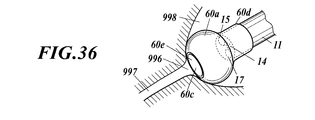
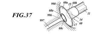
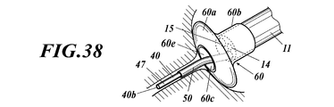
- the invention according to Claim 23 provides the endoscope system according to any one of Claims 6 to 22, wherein a distal end of the insertion portion is formed in a spherical shape or an umbrella shape. .
- the invention according to claim 24 is the method of using the endoscope system according to any one of claims 6 to 23, wherein the hydrophilic portion is wetted with the liquid by supplying the liquid to the channel, A method of use is provided, wherein the insertion portion is inserted into the channel, the distal end of the insertion portion is protruded from the distal end of the channel, and the distal end of the insertion portion is inserted into a tube. .
- the invention according to claim 25 is the method of using the endoscope system according to any one of claims 7 to 9, wherein the liquid is supplied to the catheter through the hemostasis valve by the liquid feeding device. Wetting the hydrophilic portion with the liquid, allowing the insertion portion to enter the catheter, protruding the distal end of the insertion portion from the distal end of the catheter and the channel, and connecting the distal end of the insertion portion to the tube.
- the method of use is characterized by being inserted in
- the invention according to claim 26 is the method of using the endoscope system according to claim 19, wherein the hydrophilic portion is wetted with the liquid by supplying the liquid to the channel, and the insertion portion enters the channel.
- the distal end of the insertion portion protrudes from the distal end of the channel, and the distal end of the insertion portion is inserted into the tube, and an ultrasonic diagnostic apparatus is used for the insertion of the distal end of the tube.
- a method of use characterized by observing the inside is provided.
- the invention according to claim 27 is the method of using the endoscope system according to claim 22, wherein the hydrophilic portion is wetted by the liquid by supplying the liquid to the channel, and the insertion portion enters the channel.
- the distal end of the insertion portion protrudes from the distal end of the channel, and the distal end of the insertion portion is inserted into the tube, and an ultrasonic diagnostic apparatus is used for the insertion of the distal end of the tube.
- a method of use characterized by observing the inside is provided.
- the hydrophilic portion gets wet with the liquid, slime is generated on the surface of the hydrophilic portion, and the distal end of the insertion portion of the fiberscope can be easily inserted into the thin tube.
- FIG. 1 is a perspective view of an endoscope system according to a first embodiment of the present invention. It is drawing which shows the use condition of the endoscope system which concerns on the embodiment. It is a perspective view of the fiberscope which concerns on the same embodiment. It is a front view of the distal end of the fiberscope which concerns on the same embodiment. It is a front view of the distal end of the fiberscope which concerns on the same embodiment. It is a side view of the hemostasis valve concerning the embodiment. It is a schematic sectional drawing of the input port of the hemostasis valve concerning the embodiment. It is a schematic perspective view of the input port of the hemostasis valve concerning the embodiment. It is a schematic sectional drawing of the input port of the hemostasis valve concerning the embodiment.
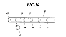
- FIG. 10 is a perspective view showing a distal portion of a fiberscope according to Modification 7.
- FIG. 10 is a perspective view for explaining a state where an ultrasonic marker is embedded in a fiberscope according to Modification 7.
- FIG. 10 is a schematic side view of a fiberscope according to Modification 7.
- FIG. 10 is a schematic side view of a fiberscope according to Modification 7.
- FIG. 10 is a schematic side view of a fiberscope according to Modification 7.
- FIG. 10 is a schematic side view of a fiberscope according to Modification 7.
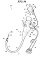
- FIG. 1 is a perspective view of the endoscope system 1.
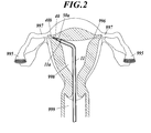
- FIG. 2 is a diagram showing a use state of the endoscope system 1.
- the endoscope system 1 is an oviduct scope guide device.
- the endoscope system 1 is a device that guides the second endoscope 30 that is an oviduct scope from outside the body to the oviduct 997 via the vagina 999 and the uterus 998.
- This endoscope system 1 is a fallopian tube observation apparatus for observing the fallopian tube 997, and an operator (a doctor or the like) first observes the vagina 999 and the uterus 998 using this endoscope system 1. -Diagnose and secondarily observe and diagnose the fallopian tube 997 and fallopian tube 995.
- the endoscope system 1 includes a first endoscope 10, a second endoscope 30, a catheter 50, a hemostasis valve 55, a liquid feeding device 70, a vaginal opening device, and the like.
- FIG. 3 is a perspective view of the second endoscope 30 as a fiberscope.
- the second endoscope 30 is an oviduct mirror.
- the second endoscope 30 includes a holding part (gripping part) 31, a disposable insertion part 40, and the like.
- proximal refers to the side close to the holding unit 31 or the holding unit 12 described later
- distal refers to the side far from the holding unit 31 or the holding unit 12 described below.
- the operator operates the second endoscope 30 with the holding unit 31.
- An eyepiece part (finder) 32 is provided on the holding part 31.
- an eyepiece optical system (eyepiece lens) 33 including one or a plurality of lenses is provided.
- the holding part 31 is provided in a case shape. Various members are accommodated in the holding portion 31, and these members are attached to the holding portion 31. Specifically, the illumination light source 34, the condensing lens 34a, the ultrasonic oscillator 35, the positioning mechanism 36, the power source 37, and the like are accommodated in the holding unit 31, and the illumination light source 34, the condensing lens 34a, the ultrasonic oscillator 35, The positioning mechanism 36, the power source 37, and the like are attached to the holding unit 31.
- the power source 37 is a battery (primary battery) or a chargeable / dischargeable battery (secondary battery).
- the power source 37 supplies power to the illumination light source 34 and the ultrasonic oscillator 35.
- the illumination light source 34 emits illumination light (mainly light in the visible light band).
- the ultrasonic oscillator 35 vibrates and emits ultrasonic waves. Note that the ultrasonic oscillator 35 may be omitted.
- the insertion portion 40 is provided in a cable shape (linear shape).
- a proximal end (base end) 40 a of the insertion portion 40 is connected to the holding portion 31 by the positioning mechanism 36, and the insertion portion 40 extends from the holding portion 31.
- the positioning mechanism 36 is a connector having a screw or an engaging portion.
- the positioning mechanism 36 locks the proximal end 40 a of the insertion portion 40 to the holding portion 31.
- the lock by the positioning mechanism 36 can be released, and the proximal end 40 a of the insertion portion 40 can be detached from the holding portion 31. Therefore, the insertion part 40 can be attached to and detached from the holding part 31.
- the insertion part 40 has flexibility.
- the insertion part 40 can be bent according to the shape of the hole into which the insertion part 40 is inserted.
- the insertion unit 40 takes in the illumination light emitted from the illumination light source 34 and collected by the condenser lens 34a into the proximal end 40a.
- the insertion part 40 guides the illumination light taken into the proximal end 40a from the proximal end 40a to the distal end (tip) 40b.
- the insertion portion 40 is guided to the distal end 40b and emits illumination light forward from the distal end 40b. Accordingly, the distal end 40b of the insertion portion 40 illuminates the vicinity of the distal end 40b of the insertion portion 40.
- the insertion unit 40 captures an image in front of the distal end 40b into the distal end 40b.
- the insertion unit 40 transmits the image captured by the distal end 40b from the distal end 40b to the proximal end 40a.
- the insertion unit 40 projects the image transmitted to the proximal end 40a from the proximal end 40a to the eyepiece optical system 33. Accordingly, the image is projected by the eyepiece optical system 33 onto the eyes of an operator looking through the eyepiece optical system 33.
- the insertion part 40 takes in the ultrasonic wave emitted from the ultrasonic oscillator 35 to the proximal end 40a and propagates the ultrasonic wave to the distal end 40b.
- the distal end 40b of the insertion portion 40 vibrates at the ultrasonic frequency. Hydrophilicity is imparted to the surface of the distal portion 40 c of the insertion portion 40. Therefore, the liquid tends to get wet on the surface of the distal portion 40 c of the insertion portion 40.
- the insertion portion 40 is formed by an extrusion method.
- FIG. 4 is a front view showing the surface of the distal end 40 b of the insertion portion 40.
- the insertion unit 40 includes a first optical fiber bundle 41, a second optical fiber bundle (light guide) 42, an ultrasonic transmission member 43, a first inner protective layer 44, a second It has an inner protective layer 45, a sheath 46 and a hydrophilic portion 47.
- the first optical fiber bundle 41 transmits an image, and the second optical fiber bundle 42 guides illumination light.
- the first optical fiber bundle 41 is composed of a plurality of optical fibers that are bundled (for example, bundled in a circular cross section).
- the second optical fiber bundle 42 includes a plurality of optical fibers bundled (for example, bundled in a crescent cross section).
- the ultrasonic transmission member 43 is a linear member.
- the ultrasonic transmission member 43 can be recognized by the ultrasonic diagnostic apparatus.
- the acoustic impedance of the ultrasonic transmission member 43 is significantly different from the acoustic impedance of a biological tissue (specifically, female genitals), and the ultrasonic transmission member 43 and the biological tissue can be distinguished by an ultrasonic diagnostic apparatus.
- the acoustic impedance of the ultrasonic transmission member 43 is significantly different from the acoustic impedance of the optical fiber bundles 41 and 42, the inner protective layers 44, 45, and 48, the sheath 46, and the hydrophilic portion 47 (see FIGS. 4 and 5).
- the bundles 41 and 42, the inner protective layers 44, 45, and 48, the sheath 46, the hydrophilic portion 47, and the ultrasonic transmission member 43 can be distinguished by the ultrasonic diagnostic apparatus.
- the ultrasonic transmission member 43 is a metal wire made of stainless steel (SUS304), gold, platinum, palladium alloy, or other metal. If the ultrasonic oscillator 35 is omitted, the ultrasonic transmission member 43 may be omitted.
- the first inner protective layer 44 covers the first optical fiber bundle 41.
- the second inner protective layer 45 covers the second optical fiber bundle 42.
- the first optical fiber bundle 41 and the second optical fiber bundle 42 are juxtaposed at a distance from each other.
- the ultrasonic transmission member 43 is arranged in parallel with the first optical fiber bundle 41 and the second optical fiber bundle 42.
- the first optical fiber bundle 41, the second optical fiber bundle 42, and the ultrasonic transmission member 43 extend along the insertion portion 40 from the distal end 40 b of the insertion portion 40 to the proximal end 40 a of the insertion portion 40. .
- the sheath 46 covers the first internal protective layer 44, the second internal protective layer 45, and the ultrasonic transmission member 43, and the first 46 from the outside of the first internal protective layer 44 and the second internal protective layer 45.
- the optical fiber bundle 41 and the second optical fiber bundle 42 are protected.
- the hydrophilic portion 47 is a layer that imparts hydrophilicity to the surface of the distal portion 40 c of the sheath 46. That is, the hydrophilic portion 47 covers the outer peripheral surface of the distal portion 40 c of the sheath 46.
- the hydrophilic portion 47 may cover at least the distal portion 40 c of the sheath 46. For example, the hydrophilic portion 47 may cover the entire outer peripheral surface of the sheath 46.
- the hydrophilic portion 47 is made of a hydrophilic material.
- a material is applied as a material for the hydrophilic portion 47.
- the matters described in these publications are incorporated by reference as matters described in this specification.
- the insertion unit 40 can be observed with an ultrasonic diagnostic apparatus.
- an ultrasonic marker is formed in the insertion portion 40 (particularly, the distal portion 40c of the insertion portion 40).
- the ultrasonic marker may be embedded in the insertion portion 40 or may be formed on the outer peripheral surface of the insertion portion 40 (the outer peripheral surface of the sheath 46).
- the ultrasonic marker refers to a member / material that can be detected by an ultrasonic diagnostic apparatus. The configuration in which the insertion unit 40 can be observed by the ultrasonic diagnostic apparatus will be described in detail later (see Modification 7).
- the ultrasonic marker formed in the insertion unit 40 can be recognized by an ultrasonic diagnostic apparatus.
- the acoustic impedance of the ultrasonic marker is greatly different from the acoustic impedance of a biological tissue (specifically, female genitals), and the ultrasonic marker and the biological tissue can be distinguished by an ultrasonic diagnostic apparatus.
- the material of the ultrasonic marker is stainless steel (SUS304), gold, platinum, palladium alloy or other metal.
- the ultrasonic marker may be formed on the outer peripheral surface of the sheath 46 by applying a material that can be recognized by the ultrasonic diagnostic apparatus (see Japanese Patent No. 4349546).
- Japanese Patent No. 4349546 Japanese Patent No. 4349546
- the first optical fiber bundle 41, the second optical fiber bundle 42, the ultrasonic transmission member 43, the first inner protective layer 44, the second inner protective layer 45, the sheath 46, and the hydrophilic portion 47 have flexibility.
- the form of the insertion portion 40 may be as shown in FIG.
- FIG. 5 is a front view showing a surface of the distal end 40b of the insertion portion 40 having a form different from that of the insertion portion 40 shown in FIG. Parts corresponding to each other between the insertion portion 40 shown in FIG. 4 and the insertion portion 40 shown in FIG. 5 are denoted by the same reference numerals.
- the insertion portion 40 includes a first optical fiber bundle 41, a second optical fiber bundle 42, a sheath 46, a hydrophilic portion 47, and an internal protective layer 48.
- the inner protective layer 48 covers the first optical fiber bundle 41, and the second optical fiber bundle 42 is bundled so as to surround the first optical fiber bundle 41 outside the inner protective layer 48.
- the second optical fiber bundle 42 is composed of a plurality of optical fibers bundled in a circular ring shape in cross section.
- the sheath 46 covers the second optical fiber bundle 42 and protects the second optical fiber bundle 42.
- the hydrophilic portion 47 covers the outer peripheral surface of the distal portion 40 c of the sheath 46.
- the ultrasonic transmission member 43 may or may not be provided inside the insertion portion 40 shown in FIG.
- the configuration of the distal end 40b of the insertion portion 40 shown in FIG. 5 is the same as the configuration of the distal end 40b of the insertion portion 40 shown in FIG. 4 and 5, the distal end (tip) of the first optical fiber bundle 41 is exposed at the distal end 40 b of the insertion portion 40.
- the imaging lens is provided in the sheath 46 before the distal end of the first optical fiber bundle 41, and the imaging lens is exposed at the distal end 40 b of the insertion portion 40. The imaging lens forms an image in front of the distal end of the first optical fiber bundle 41 on the distal end of the first optical fiber bundle 41.
- the distal end (tip) of the second optical fiber bundle 42 is exposed at the distal end 40b of the insertion portion 40.
- the projection lens is provided on the sheath 46 before the distal end of the second optical fiber bundle 42, and the lens is exposed at the distal end 40 b of the insertion portion 40.
- the projection lens projects illumination light emitted from the distal end of the second optical fiber bundle 42 to the front of the distal end of the second optical fiber bundle 42.
- the imaging lens and the projection lens may be shared as one lens.
- the proximal end (base end) of the first optical fiber bundle 41 is exposed at the proximal end 40 a of the insertion portion 40. That is, the proximal end of the first optical fiber bundle 41 is not covered with the first inner protective layer 44 and the sheath 46. The same applies to the proximal end of the second optical fiber bundle 42.
- the configuration of the proximal end 40a of the insertion portion 40 shown in FIG. 5 is the same as the configuration of the proximal end 40a of the insertion portion 40 shown in FIG. 4 and 5, when the proximal end 40 a of the insertion portion 40 is connected to the holding portion 31 by the positioning mechanism 36 as shown in FIG. 1, the positioning mechanism 36 is connected to the first optical fiber bundle 41.
- the position of the proximal end is determined, and the proximal end of the first optical fiber bundle 41 is opposed to the eyepiece optical system 33.
- the positioning mechanism 36 determines the position of the proximal end of the second optical fiber bundle 42 and makes the proximal end of the second optical fiber bundle 42 face the condenser lens 34 a and the illumination light source 34.
- the positioning mechanism 36 determines the position of the proximal end of the ultrasonic transmission member 43 and connects the proximal end of the ultrasonic transmission member 43 to the ultrasonic oscillator 35.
- the first endoscope 10 is a hysteroscope (hysteroscope).
- the first endoscope 10 is described in US Pat. No. 4,911,148, US Pat. No. 4,836,189, US Pat. No. 4,777,612, US Pat. No. 4,461,634, US Pat.
- the first endoscope 10 is a viewing mirror described in International Publication No. 95/24149.
- the matters described in these publications are incorporated by reference as matters described in this specification.
- the first endoscope 10 is a fiber scope or a video scope.
- the first endoscope 10 includes an insertion part 11 and a holding part 12.
- the proximal end (base end) of the insertion portion 11 is connected to the holding portion 12, and the insertion portion 11 extends from the holding portion 12.
- the first endoscope 10 is a soft mirror, and the insertion portion 11 has flexibility.
- the distal portion 11b of the insertion portion 11 has a bending function, and the distal portion 11b of the insertion portion 11 can be remotely bent by an operator. For example, when the operator operates the holding portion 12, the distal portion 11 b of the insertion portion 11 performs a bending operation, and the orientation of the distal end (tip) 11 a of the insertion portion 11 can be changed.
- An eyepiece (finder) 13 is provided on the holding unit 12.
- An image in front of the distal end 11a of the insertion part 11 is projected on the eyepiece part 13, and the operator can observe and diagnose the front of the distal end 11a of the insertion part 11 by looking into the eyepiece part 13. it can.
- the first endoscope 10 is a fiberscope
- an objective lens as an image input unit 14 is provided at the distal end 11 a of the insertion unit 11, and an optical fiber bundle for images travels far inside the insertion unit 11 and the holding unit 12. Wiring is performed from the distal end 11 a to the eyepiece 13, and an eyepiece is provided on the eyepiece 13.
- An image in front of the distal end 11a of the insertion portion 11 is formed on the distal end of the optical fiber bundle by the objective lens, the image is transmitted to the proximal end of the optical fiber bundle by the optical fiber bundle, and the image is emitted by the eyepiece. And projected onto the eyes of the operator.
- a small electronic camera (the electronic camera is composed of an objective lens, an image sensor, etc.) as the image input unit 14 is provided at the distal end 11 a of the insertion unit 11.
- the transmission cable is wired from the distal end 11 a to the eyepiece 13 in the insertion portion 11 and the holding portion 12, and an eyepiece and a display element are provided in the eyepiece 13.
- An image in front of the distal end 11a of the insertion portion 11 is captured by an electronic camera, the image is transmitted as an image signal to a display element by a transmission cable, the image is displayed by the display element, and the displayed image is an eyepiece. Is projected onto the operator's eyes and the like.
- the transmission cable wired from the image input unit 14 to the holding unit 12 is further wired to a display device outside the holding unit 12, and the image signal of the image captured by the image input unit 14 is externally displayed by the transmission cable.
- the image may be transmitted to the device and the image displayed on the display device.
- the display element and the eyepiece unit 13 may be provided in the holding unit 12 or may not be provided.
- the illumination light is emitted from the illumination unit 15 at the distal end 11a of the insertion unit 11.
- An illumination light source 16 is provided in the holding unit 12, an optical fiber or an optical fiber bundle is wired in the holding unit 12 and the insertion unit 11 from the illumination light source 16 to the illumination unit 15, and a distal end of the optical fiber or the optical fiber bundle or an illumination lens is inserted in the insertion unit. 11, the distal end of an optical fiber or optical fiber bundle or an illumination lens is the illumination unit 15.
- the illumination light source 16 When the illumination light source 16 is turned on, the light emitted from the illumination light source 16 propagates to the illumination unit 15 through an optical fiber or an optical fiber, and the light is emitted from the illumination unit 15.
- the illumination light source 16 may be provided at the distal end 11 a of the insertion unit 11, and the illumination light source 16 may be the illumination unit 15.
- the insertion part 11 of the endoscope 10 can be observed with an ultrasonic diagnostic apparatus.
- the first endoscope 10 is a tubular structure having a channel 17 as a hollow. That is, the channel 17 is provided in the insertion portion 11 along the longitudinal direction of the insertion portion 11, one end (proximal end) of the channel 17 opens at the surface of the holding portion 12, and the other end (distal end) of the channel 17. Opens at the distal end 11 a of the insertion portion 11. Since the insertion portion 11 is flexible, the first endoscope 10 is a flexible tubular structure.
- the channel 17 is a forceps channel.
- a channel 18 is formed inside the holding portion 12, one end 18 a of the channel 18 opens at the surface of the holding portion 12, and the other end 18 b of the channel 18 joins the middle portion of the channel 17.
- the opening of one end 18a of the channel 18 is closed by a cap or the like, or the port adapter 19 is attached to the opening.
- the port adapter 19 is provided with a valve mounting portion 19a, and various valves can be mounted on the valve mounting portion 19a. Further, the port adapter 19 is provided with an inlet port 19b, and this inlet port 19b is provided with a syringe (syringe), a pump, a perfusion system (the perfusion system is composed of a pump or the like) or an infusion bag (an infusion bag) via a tube. It is connected.
- the catheter 50 is inserted into the channel 17 from the opening at one end (proximal end) of the channel 17, and the distal portion 50 a of the catheter 50 extends from the opening on the opposite side of the channel 17.
- the catheter 50 is a tubular structure having a hollow, and the catheter 50 is provided in a tubular shape.
- the catheter 50 is a flexible tubular structure, and the catheter 50 is flexible. Since the catheter 50 is inserted into the channel 17 of the first endoscope 10, the first endoscope 10 and the catheter 50 constitute a double tubular structure.
- the catheter 50 (particularly, the distal portion 50a of the catheter 50) can be observed by an ultrasonic diagnostic apparatus.
- an ultrasonic marker is formed on the catheter 50 (particularly, the distal portion 50a of the catheter 50).
- the ultrasonic marker may be embedded in the catheter 50 or may be formed on the outer peripheral surface of the catheter 50. In any case, the hollow of the catheter 50 is not blocked by the ultrasonic marker.
- FIG. 6 is a side view of the hemostasis valve 55.
- the hemostasis valve 55 has a configuration similar to a three-way stopcock.
- the hemostasis valve 55 includes an output port 55a, a first input port 55b, a second input port 55c, a main body portion 55d, a flow path 55e, and the like.
- a first input port 55b, a second input port 55c, and a second output port 55a are provided in the main body 55d.
- the flow path 55e is a hollow provided inside the main body 55d.
- the channel 55e and the main body 55d are provided in a Y shape. That is, a part of the flow path 55e is linearly provided from the first input port 55b to the first output port 55a, the first input port 55b is provided at one end of the linearly provided portion, and the other end is provided.
- the first output port 55a is provided, the flow path 55e is branched in the middle between the first input port 55b and the first output port 55a, and the second input port 55c is provided at the end of the divided portion. Yes.
- the output port 55a of the hemostasis valve 55 is connected to the proximal end of the catheter 50.
- the insertion portion 40 of the second endoscope 30 is inserted into the first input port 55b of the hemostasis valve 55, the insertion portion 40 is passed through the hemostasis valve 55 and the catheter 50, and the distal end 40b of the insertion portion 40 is inserted. Extends from the opening at the distal end of the catheter 50.
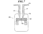
- FIG. 7 to 11 are drawings for explaining the first input port 55b of the hemostasis valve 55.
- FIG. The fluid in the flow path 55e does not leak from the first input port 55b. That is, the first input port 55b is in a closed state, and the fluid in the flow path 55e does not leak to the outside through the first input port 55b. Further, when the insert is inserted into the first input port 55b, the insert is held in the first input port 55b and there is no gap in the first input port 55b, so that the fluid in the flow path 55e is transferred to the first input port 55b. No leakage outside through 55b.
- the first input port 55b is provided with a check valve 55f made of an elastic member such as rubber.
- the check valve 55f has a cut 55g.
- the cut 55g is closed by the elastic force of the check valve 55f, and the fluid in the flow path 55e does not leak through the cut 55g.
- the notch 55g opens against the elastic force of the check valve 55f, and the insert is inserted into the notch 55g of the check valve 55f. There is no gap between 55f. Therefore, the fluid in the flow path 55e does not leak.
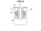
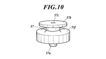
- the cylindrical member 57 When inserting the insertion portion 40 of the second endoscope 30 into the first input port 55b, the cylindrical member 57 is used.
- the cylindrical member 57 is provided in a cylindrical shape having a hollow 57 c, one end portion 57 a of the cylindrical member 57 is tapered, and a flange 57 b is provided at the other end portion of the cylindrical member 57.
- the notch 55g of the check valve 55f opens, and the cylindrical member 57 is held by the notch 55g of the check valve 55f. (See FIGS. 9 and 10). Since there is no gap between the cylindrical member 57 and the check valve 55f, no fluid leaks at this portion.
- the operator With the tubular member 57 inserted into the check valve 55f, the operator inserts the insertion portion 40 of the second endoscope 30 into the hollow 57c of the tubular member 57 and the first input port 55b.
- the notch 55g of the check valve 55f is closed by the elastic force of the check valve 55f, and the insertion portion 40 of the second endoscope 30 is moved to the check valve. It is held in the notch 55g of 55f (see FIG. 11). Since there is no gap between the insertion portion 40 of the second endoscope 30 and the check valve 55f, no fluid leaks at this portion.
- the tubular member 57 is also used when the insertion portion 40 of the second endoscope 30 is pulled out from the first input port 55b. That is, a doctor or the like inserts the cylindrical member 57 into the check valve 55f, and in that state, pulls out the insertion portion 40 of the second endoscope 30 from the hollow 57c of the cylindrical member 57 and the first input port 55b. Then, the tubular member 57 is pulled out from the check valve 55f.
- the number of check valves 55f may be one or more. When there are a plurality of check valves 55f, the plurality of check valves 55f are overlapped so that fluid leakage can be reliably prevented.
- FIG. 12 is a perspective view of a fixture 59 for fixing the hemostasis valve 55 to the holding portion 12.
- FIG. 13 is a perspective view showing the hemostasis valve 55, the fixture 59, the holding portion 12, and the like.
- the hemostasis valve 55 is held by the holding portion 12 by a fixture 59.
- the fixture 59 is a clip pair. That is, the fixture 59 has a first clip 59a and a second clip 59b.
- the first clip 59a is made of a C-shaped elastic member
- the second clip 59b is made of a C-shaped elastic member.
- the open portion of the first clip 59a is opposite to the open portion of the second clip 59b, and the second clip 59b is connected to the first clip 59a.
- the first clip 59a holds the holding portion 12 so as to sandwich the holding portion 12
- the second clip 59b holds the main body portion 55d of the hemostasis valve 55 so as to sandwich the main body portion 55d of the hemostasis valve 55. Accordingly, the hemostasis valve 55 is fixed to the holding portion 12.
- the second input port 55 c is connected to one end of a flexible catheter 58, and the other end of the catheter 58 is connected to the liquid delivery device 70.
- the liquid feeding device 70 stores liquid (for example, sterilized water and physiological saline) and sends the liquid to the catheter 58, hemostasis valve 55, and catheter 50.
- the liquid feeding device 70 is an electric pump or a manual pump.
- the liquid feeding device 70 is a manual or electric syringe pump.
- the catheter 58 can be attached to and detached from the liquid feeding device 70.
- the insertion part 40, the catheter 50, the hemostasis valve 55, the catheter 58 and the tubular member 57 are disposable.
- the unused insertion part 40, the catheter 50, the hemostasis valve 55, the catheter 58, and the cylindrical member 57 are packed in an assembled state. That is, as shown in FIGS. 9 and 10, the cylindrical member 57 is attached to the check valve 55 f of the first input port 55 b, and the insertion portion 40 is a hollow 57 c of the cylindrical member 57, a hemostasis valve.
- the insertion portion 40, the catheter 50, the hemostasis valve 55, the catheter 58, and the tubular member 57 are packed in a state of being inserted into the flow path 55 e of 55 and the catheter 50. Further, in a state where the insertion portion 40, the catheter 50, the hemostasis valve 55, the catheter 58 and the tubular member 57 are packed, the catheter 50 is wound together with the insertion portion 40 in a ring shape.
- a method for using the endoscope system 1 will be described, and a diagnosis method using the endoscope system 1 will be described.
- An operator such as a doctor removes the insertion portion 40, the catheter 50, the hemostasis valve 55, the catheter 58 and the tubular member 57 packed in the package from the package.
- the insertion part 40, the catheter 50, the hemostasis valve 55, the catheter 58, and the cylindrical member 57 may be packed separately. In this case, after inserting the insertion part 40, the catheter 50, the hemostasis valve 55, the catheter 58 and the cylindrical member 57 from each package, these are assembled.
- the tubular member 57 is inserted into the check valve 55f of the first input port 55b, the catheters 50 and 58 are connected to the hemostasis valve 55, and the insertion portion 40 is connected to the hollow 57c of the tubular member 57 and the hemostasis valve 55. Are inserted into the flow path 55e and the catheter 50.
- the proximal end 40 a of the insertion portion 40 is attached to the holding portion 31, and the proximal end 40 a of the insertion portion 40 is fixed to the holding portion 31 by the positioning mechanism 36.
- the distal end 40 b of the insertion portion 40 is aligned with the distal end of the catheter 50 by moving the insertion portion 40 forward or backward, or the distal end 40 b of the insertion portion 40 is drawn into the catheter 50.
- the tubular member 57 is pulled out from the check valve 55f and the first input port 55b, the check valve 55f and the first input port 55b are closed, and the insertion portion 40 is fixed by the check valve 55f.
- the catheter 58 is connected to the liquid feeding device 70 and a liquid such as a sterilizing solution is supplied to the liquid feeding device 70.
- the opening of one end 18a of the channel 18 is closed with a cap or the like, or the port adapter 19 is attached to the opening.
- a valve is attached to the valve attachment portion 19a, and a syringe, a pump, a perfusion system or an infusion bag is connected to the inlet port 19b.
- a liquid such as a sterilizing solution is supplied to the syringe.
- a liquid such as a sterilizing liquid is supplied to a tank (liquid supply source) of a pump or a perfusion system. Liquid such as sterilization liquid is stored in the drip bag.
- the operator inserts the catheter 50 together with the insertion portion 40 into one end (proximal end) of the channel 17, and the distal end 40 b of the insertion portion 40 and the distal end of the catheter 50 are connected to the other end (distant end) of the channel 17.
- the insertion portion 40 and the catheter 50 are advanced into the channel 17 so as not to come out from the distal end.
- the hemostasis valve 55 is fixed to the holding portion 12 by the fixing tool 59.
- vaginal opening device (Cusco, vagina tube) into the vagina 999, and opens the vaginal opening and vagina 999 with the open vaginal device.
- the vaginal opening may or may not be provided with a holder for holding the first endoscope 10.
- the vaginal opening device provided with the holder will be described in detail later (refer to the sixth to ninth embodiments). It is not necessary to use a vaginal opening device.
- the operator inserts the insertion portion 11 into the vaginal opening and introduces the insertion portion 11 into the vagina 999 and the uterus 998 in this order.
- the insertion unit 11 since the illumination light source 16 is turned on, the illumination light emitted from the illumination light source 16 is guided to the illumination unit 15 by an optical fiber or an optical fiber bundle, and the illumination light is emitted from the illumination unit 15.
- the image in front of the illumination unit 15 is captured by the image input unit 14, the operator can perform observation and diagnosis in front of the image input unit 14 by looking into the eyepiece unit 13. The operator introduces the insertion portion 11 into the vagina 999 and the uterus 998 while performing such observation and diagnosis.
- the fallopian tube 996 refers to the end of the fallopian tube 997 that opens in the inner wall of the uterus 998.
- the insertion portion 11 and / or the holding portion 12 of the first endoscope 10 are attached to the holder, and the first endoscope 10 is fixed to the vaginal opening device.
- the holder preferably biases (pushes out) the insertion portion 11 or the holding portion 12 or both in the direction in which the insertion portion 11 is inserted into the vagina 999.
- the operator enters the catheter 50 into the channel 17, the distal end of the catheter 50 protrudes from the distal end of the channel 17, and the distal end of the catheter 50 is slightly moved to the fallopian tube 996 of the fallopian tube 997. Insert into.
- the distal end of the catheter 50 protrudes from the distal end of the channel 17, liquid is fed by the liquid feeding device 70 as necessary, and the liquid is inside the channel 17 and inside the catheter 50.
- the fluid is allowed to flow and the liquid is ejected from the distal end of the catheter 50. If it does so, the part 50a of the distal side of the catheter 50 will slip easily with respect to the oviduct 997 with the ejected liquid, and it will become easy to insert the distal end of the catheter 50 in the oviduct 997. Even if the liquid is supplied to the flow path 55e of the hemostasis valve 55 by the liquid feeding device 70, the check valve 55f is closed, so that the liquid does not leak from the first input port 55b. Since the catheter 50 is inserted into the channel 17, the liquid flows inside the channel 17 and inside the catheter 50.
- the ultrasonic oscillator 35 when the distal end of the catheter 50 is protruded from the distal end of the channel 17, the ultrasonic wave is propagated to the distal end 40 b of the insertion portion 40 by the ultrasonic transmission member 43.
- the distal end of the catheter 50 is ultrasonically vibrated together with the distal end 40b of the insertion portion 40. It becomes easy to insert the distal end of the catheter 50 into the fallopian tube 997.
- the liquid is fed by the liquid feeding device 70, and the liquid is ejected from the distal end of the catheter 50.
- the ejected liquid is filled in the oviduct 997.
- the oviduct 997 becomes straight, it becomes easy to introduce the insertion part 40.
- surroundings of the distal end 40b of the insertion part 40 are satisfy
- the liquid is supplied to the channels 18 and 17 by a syringe, a pump, a perfusion system or an infusion bag together with the liquid feeding by the liquid feeding device 70. May be.
- the liquid is supplied to the channels 18 and 17, the liquid is ejected from the distal end of the channel 17.
- the distal portion of the catheter 50 and the distal portion 40c of the insertion portion 40 are wetted by the liquid. If the catheter 50 is inserted into the proximal end of the channel 17 via packing or the like, the liquid supplied to the channels 17 and 18 can be prevented from being ejected from the proximal end of the channel 17.
- the operator inserts one end 57a of the cylindrical member 57 into the cut 55g of the check valve 55f. Then, the notch 55g of the check valve 55f is opened, the check valve 55f is separated from the insertion portion 40, and the fixing of the insertion portion 40 by the check valve 55f is released. Therefore, the insertion portion 40 can be taken in and out of the hollow 57 c of the cylindrical member 57.
- the operator causes the insertion portion 40 to enter the catheter 50, the distal end 40 b of the insertion portion 40 protrudes from the distal end of the catheter 50, and the distal end 40 b of the insertion portion 40 is inserted into the oviduct 997. . Then, the operator further inserts the insertion portion 40 into the catheter 50 and introduces the distal end 40b of the insertion portion 40 as far as possible into the deepest of the fallopian tube 997, up to the fallopian tube 995.
- the liquid in the fallopian tube 997 (liquid ejected from the catheter 50) wets well with the hydrophilic portion 47 of the insertion portion 40 and the liquid is not repelled from the hydrophilic portion 47.
- slime occurs on the surface of the hydrophilic portion 47. Accordingly, the distal portion 40c of the insertion portion 40 is easily slipped with respect to the fallopian tube 997 by the liquid, and the distal end 40b of the insertion portion 40 is easily introduced into the fallopian tube 997 and the fallopian tube 995.
- the liquid feeding device 70 When the insertion portion 40 is inserted into the oviduct 997, the liquid is fed by the liquid feeding device 70 (when the port adapter 19 is attached to the opening of the one end 18a of the channel 18, the liquid feeding device 70 feeds the liquid.
- liquid may be supplied to the channels 18, 17 by syringe, pump, perfusion system or infusion bag), and the liquid may be injected or refilled into the oviduct 997.
- Either the step of inserting the insertion portion 40 into the oviduct 997 or the step of blowing the liquid from the distal end of the catheter 50 by the liquid delivery device 70 may be performed first, or these steps may be performed simultaneously.
- a guide wire is inserted into the fallopian tube, then a catheter is inserted into the fallopian tube using the guidewire, then the guidewire is pulled out, and then the catheter is The oviduct mirror was inserted into the fallopian tube.
- the distal portion 40c of the insertion portion 40 can be inserted into the oviduct 997. This is because the hydrophilic portion 47 provided in the distal portion 40c of the insertion portion 40 is easily wetted by the liquid, and the hydrophilic portion 47 is slidable with respect to the oviduct 997.
- the ultrasonic oscillator 35 is activated when the distal end 40b of the insertion portion 40 is inserted into the fallopian tube 997 or the fallopian tube 995 or both, the ultrasonic wave is transmitted to the distal portion of the insertion portion 40 by the ultrasonic transmission member 43. Propagating to the end 40b, the distal end 40b of the insertion portion 40 vibrates ultrasonically. It becomes easy to insert the distal end 40 b of the insertion portion 40 into the oviduct 997.
- the illumination light source 34 Since the illumination light source 34 is turned on when the insertion portion 40 is inserted, the illumination light emitted from the illumination light source 34 is guided to the distal end of the second optical fiber bundle 42 by the second optical fiber bundle 42, Illumination light is emitted from the distal end of the second optical fiber bundle 42.
- an image in front of the distal end 40 b of the insertion portion 40 is taken into the distal end of the first optical fiber bundle 41, and the image is transmitted to the proximal end by the first optical fiber bundle 41. Therefore, the operator can observe and diagnose the fallopian tube 997 or fallopian tube 995 or both by looking into the eyepiece optical system 33 of the eyepiece 32. The operator introduces the insertion portion 40 into the fallopian tube 997 while performing such observation and diagnosis.
- the operator pulls out the insertion portion 40 from the catheter 50 and pulls out the distal end 40b of the insertion portion 40 from the fallopian tube 997.
- the liquid is blown out from the distal end of the catheter 50 by the liquid feeding device 70 (when the port adapter 19 is attached to the opening of the one end 18a of the channel 18)
- liquid may be supplied to channels 18, 17 by syringe, pump, perfusion system or infusion bag), and liquid may be injected or refilled into oviduct 997.
- an operator may observe and diagnose the fallopian tube 997 and / or fallopian tube 995 by looking into the eyepiece optical system 33 of the eyepiece part 32.
- the operator pulls out the catheter 50 from the channel 17, pulls out the distal end of the catheter 50 from the fallopian tube 996, and pulls the distal end of the catheter 50 into the channel 17.
- the operator operates the holding portion 12 to pull out the insertion portion 11 from the uterus 998 and the vagina 999 while straightening the distal portion 11 b of the insertion portion 11.
- the operator removes the fixture 59 from the holding portion 12 and removes the fixture 59 from the hemostasis valve 55. Then, the operator pulls out the catheter 50 together with the insertion portion 40 from the channel 17.
- the operator removes the proximal end 40 a of the insertion portion 40 from the holding portion 31 and removes the catheter 58 from the liquid delivery device 70. Then, the operator discards the insertion portion 40, the catheter 50, the hemostasis valve 55, the catheter 58, and the tubular member 57.
- FIG. 14 is a perspective view of the endoscope system 1A.
- FIG. 15 is a view showing a use state of the endoscope system 1A. Parts corresponding to each other between the endoscope system 1A in the second embodiment and the endoscope system 1 in the first embodiment are denoted by the same reference numerals.
- the difference between the endoscope system 1A in the second embodiment and the endoscope system 1 in the first embodiment resides in the catheter 50, the hemostasis valve 55, the catheter 58, and the liquid feeding device 70. That is, the endoscope system 1A does not include the catheter 50, the hemostasis valve 55, the catheter 58, and the liquid feeding device 70.
- the first endoscope 10 has a port adapter 19 attached to the opening of one end 18a of the channel 18, and a syringe, a pump, a perfusion system, or an infusion bag is connected to the port adapter 19 via a tube. Connected to the inlet port 19b.
- the insertion part 40 is disposable. The unused insertion part 40 is packed in the state wound by the ring shape.
- portions corresponding to each other between the endoscope system 1A in the second embodiment and the endoscope system 1 in the first embodiment are similarly provided.
- the usage method of the endoscope system 1A in the second embodiment is substantially the same as the usage method of the endoscope system 1 in the first embodiment.
- a method of using the endoscope system 1A in the second embodiment will be described.
- the operator When using the endoscope system 1A, the operator first takes out the insertion portion 40 packed in the package from the package. Next, the proximal end 40 a of the insertion portion 40 is attached to the holding portion 31, and the proximal end 40 a of the insertion portion 40 is fixed to the holding portion 31 by the positioning mechanism 36. Next, the operator inserts the insertion portion 40 into one end (proximal end) of the channel 17 so that the distal end 40b of the insertion portion 40 does not protrude from the other end (distal end) of the channel 17. 40 enters channel 17.
- the insertion portion 40 is inserted directly into the channel 17 or inserted through a valve (for example, a check valve), a packing or a plug (for example, a plug described in Japanese Utility Model Publication No. 55-70108).
- the part 40 is inserted into the channel 17.
- the insertion portion 40 When using a valve, packing, or the like, the insertion portion 40 is passed through a valve (for example, a check valve), packing, or the like, and when the insertion portion 40 is inserted into the channel 17, the valve, the packing, or the like is inserted into the channel 17. Fit into the opening at the proximal end of the. In this way, liquid leakage at the opening at the proximal end of the channel 17 can be prevented.
- a valve for example, a check valve
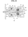
- FIG. 16 is a cross-sectional view showing a plug 90 provided at one end (proximal end) of the channel 17.
- This plug 90 is shown in FIGS. 1, 2 and 3 of Japanese Utility Model Publication No. 55-70108.
- one end (proximal end) of the channel 17 opens at the protruding end of the nipple (forceps mouth portion) 12a, and a plug body (forceps mouth body) 91 is inserted into the channel 17 inside the nipple 12a.
- An elastic ring (rubber ring) 92 is sandwiched between the plug main body 91 and the nipple 12a, the fixing ring 93 is externally mounted on the plug main body 91, and the fixing ring 93 is screwed onto the outer periphery of the nipple 12a.
- the hole 91 a of the plug body 91 is connected to the nipple 12 a and communicates with the channel 17.
- An opening 91b is formed at the tip of the plug body 91, and the opening 91b communicates with the hole 91a.
- a ring-shaped elastic packing (rubber packing) 94 and a ring-shaped operation member 95 are accommodated in the opening 91b.
- the operation ring 96 is screwed onto the outer peripheral surface of the stopper main body 91, and a flange (pressing piece) 96 a is provided on the inner periphery of the operation ring 96.
- a flange (pressing piece) 96 a is provided on the inner periphery of the operation ring 96.
- the operator After inserting the insertion portion 40 into the channel 17, the operator opens the vaginal opening and vagina 999 with the open vaginal device, inserts the insertion portion 11 into the open vaginal device, and inserts the insertion portion 11 into the vagina 999 and the uterus 998 in order. Introduce.
- the insertion unit 11 since the illumination light source 16 is turned on, the illumination light emitted from the illumination light source 16 is guided to the illumination unit 15 by an optical fiber or an optical fiber bundle, and the illumination light is emitted from the illumination unit 15.
- the image in front of the illumination unit 15 is captured by the image input unit 14, the operator can perform observation and diagnosis in front of the image input unit 14 by looking into the eyepiece unit 13. The operator introduces the insertion portion 11 into the vagina 999 and the uterus 998 while performing such observation and diagnosis.
- the operator operates the holding portion 12 to bend the distal portion 11 b of the insertion portion 11 and direct the distal end 11 a of the insertion portion 11 toward the fallopian tube opening 996 of the fallopian tube 997. Then, the operator operates the holding portion 12 so that the distal end 11a of the insertion portion 11 is lightly brought into contact with the oviduct opening 996 or the distal end 11a is inserted into the oviduct opening 996. At this time, a liquid may be fed by a syringe, a pump, a perfusion system, or an infusion bag, and the liquid may be ejected from the distal end of the channel 17.
- the operator inserts the insertion portion 40 into the channel 17, slightly protrudes the distal end 40 b of the insertion portion 40 from the distal end of the channel 17, and moves the distal end 40 b of the insertion portion 40 to the oviduct 997. Insert a little into the fallopian tube 996. Then, the operator temporarily stops the insertion portion 40 (see FIG. 15).
- a liquid is sent to the channel 17 by a syringe, a pump, a perfusion system, or an infusion bag, and the liquid is ejected from the distal end of the channel 17.
- This fills the oviduct 997 with liquid. If a valve or packing or the like is fitted in the opening at the proximal end of the channel 17, the liquid sent to the channel 17 by a syringe, a pump, a perfusion system or an infusion bag will not be ejected from the proximal end of the channel 17. Can be.
- the insertion portion 40 can be easily introduced in the same manner as in the first embodiment, and the periphery of the distal end 40b of the insertion portion 40 is filled with the liquid. The same is true in that the front field of view of the distal end of one optical fiber bundle 41 becomes clear.
- the operator further inserts the insertion portion 40 into the channel 17 and introduces the distal end 40b of the insertion portion 40 up to the fallopian tube 995.
- the liquid in the oviduct 997 (liquid ejected from the channel 17) is well wetted by the hydrophilic portion 47 of the insertion portion 40, and the liquid is not repelled from the hydrophilic portion 47, so that the surface of the hydrophilic portion 47 is not smooth. Arise. Therefore, it becomes easy to introduce the distal end 40b of the insertion portion 40 into the oviduct 997.
- a liquid may be fed by a syringe, a pump, a perfusion system, or an infusion bag, and the liquid may be injected or supplemented into the fallopian tube 997.
- the ultrasonic oscillator 35 may be activated.
- the operator observes and diagnoses the fallopian tube 997 and / or the fallopian tube 995 as the operator peeks into the eyepiece optical system 33 of the eyepiece 32 while further inserting the insertion portion 40 into the channel 17.
- the operator pulls out the insertion portion 40 from the channel 17, pulls out the distal end 40 b of the insertion portion 40 from the oviduct 997, and pulls the distal end 40 b of the insertion portion 40 into the channel 17.
- the liquid may be blown from the distal end of the channel 17 by a syringe, a pump, a perfusion system, or an infusion bag, and the liquid may be injected or refilled into the oviduct 997.
- the operator operates the holding portion 12 to remove the distal end 11a of the insertion portion 11 from the fallopian tube opening 996 of the fallopian tube 997 and insert it while straightening the distal portion 11b of the insertion portion 11.
- Part 11 is withdrawn from uterus 998 and vagina 999.
- the insertion portion 40 is pulled out from the channel 17.
- the proximal end 40a of the insertion portion 40 is removed from the holding portion 31, and the insertion portion 40 is discarded.
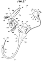
- FIG. 17 is a perspective view of the endoscope system 1B. Parts corresponding to each other between the endoscope system 1B in the third embodiment and the endoscope system 1 in the first embodiment are denoted by the same reference numerals.
- the catheter 50 is different from the endoscope system 1B in the third embodiment and the endoscope system 1 in the first embodiment. That is, the endoscope system 1B does not have the catheter 50.
- the output port 55a of the hemostasis valve 55 is connected to the opening of one end (proximal end) of the channel 17. Specifically, the output port 55a of the hemostasis valve 55 is directly screwed into, engaged with, or fitted to the opening at one end of the channel 17. Alternatively, the output port 55a of the hemostasis valve 55 is connected to the opening at one end of the channel 17 by a joint (for example, a luer lock).
- a joint for example, a luer lock
- the output port 55a of the hemostasis valve 55 is connected to the luer lock, and the luer lock is connected to the opening at one end of the channel 17, or the output port 55a of the hemostasis valve 55 is connected to the adapter.
- the adapter is threadedly engaged with or engaged with the luer lock, and the luer lock is connected to the opening at one end of the channel 17.
- the unused insertion part 40, hemostasis valve 55, catheter 58 and cylindrical member 57 are packed in an assembled state. That is, as shown in FIGS. 9 and 10, the cylindrical member 57 is mounted on the check valve 55 f of the first input port 55 b, and the insertion portion 40 is the hollow 57 c of the cylindrical member 57 and the hemostasis valve.
- the insertion portion 40, hemostasis valve 55, catheter 58, and tubular member 57 are packed in a state of being penetrated by the flow path 55 e of 55. Further, in a state where the insertion portion 40, the hemostasis valve 55, the catheter 58, and the cylindrical member 57 are packed, the insertion portion 40 is wound in a ring shape.
- portions corresponding to each other between the endoscope system 1B in the third embodiment and the endoscope system 1 in the first embodiment are similarly provided.
- the usage method of the endoscope system 1B in the third embodiment is substantially the same as the usage method of the endoscope system 1 in the first embodiment.
- a method of using the endoscope system 1B in the third embodiment will be described.
- an operator When using the endoscope system 1B in the third embodiment, an operator first takes out the insertion portion 40, hemostasis valve 55, catheter 58 and tubular member 57 from the package. Next, the operator connects the catheter 58 to the liquid feeding device 70 and supplies a liquid (for example, a sterilizing solution or physiological saline) to the liquid feeding device 70.
- a liquid for example, a sterilizing solution or physiological saline
- the insertion part 40, hemostasis valve 55, catheter 58, and the cylindrical member 57 are packed separately, the insertion part 40, hemostasis valve 55, catheter 58, and the cylindrical member 57 are taken out from each package.
- the tubular member 57 is inserted into the check valve 55f of the first input port 55b, the catheter 58 is connected to the hemostasis valve 55, and the insertion portion 40 is connected to the hollow 57c of the tubular member 57 and the hemostasis valve 55.
- the catheter 58 is connected to the liquid feeding device 70 through the flow path 55e, and a liquid such as a sterilizing solution is supplied to the liquid feeding device 70.
- the operator inserts the insertion portion 40 into one end (proximal end) of the channel 17 and connects the output port 55a of the hemostasis valve 55 to one end (proximal end) of the channel 17. Then, the insertion portion 40 is caused to enter the channel 17 so that the distal end 40 b of the insertion portion 40 does not come out of the other end (distal end) of the channel 17. Next, the tubular member 57 is removed from the check valve 55f and the first input port 55b, and the insertion portion 40 is fixed to the check valve 55f.
- the operator introduces the insertion part 11 into the vagina 999 and the uterus 998 in order through the open vagina. Then, the operator operates the holding portion 12 so that the distal end 11a of the insertion portion 11 is lightly brought into contact with the fallopian tube opening 996, or the distal end 11a is slightly inserted into the fallopian tube opening 996.
- the operator inserts the cylindrical member 57 into the check valve 55f and the first input port 55b, and releases the insertion portion 40 from the check valve 55f. Then, the operator causes the insertion portion 40 to enter the hemostasis valve 55 and the channel 17, slightly protrudes the distal end 40 b of the insertion portion 40 from the distal end of the channel 17, and moves the distal end 40 b of the insertion portion 40. Insert a little into the fallopian tube 996 of the fallopian tube 997.
- the operator removes the cylindrical member 57 from the check valve 55f and the first input port 55b, and closes the check valve 55f. Then, the liquid is fed to the channel 17 by the liquid feeding device 70, and the liquid is ejected from the distal end of the channel 17. This fills the oviduct 997 with liquid and straightens the oviduct 997. Therefore, it becomes easy to introduce the insertion part 40.
- the operator removes the cylindrical member 57 from the check valve 55f and the first input port 55b, and closes the check valve 55f. Then, the operator further inserts the insertion portion 40 into the channel 17 and introduces the distal end 40b of the insertion portion 40 up to the tubal fold 995 at the maximum. Since the liquid in the oviduct 997 is well wetted by the hydrophilic portion 47 of the insertion portion 40, the distal end 40b of the insertion portion 40 can be easily introduced into the oviduct 997.
- a liquid may be fed by the liquid feeding device 70, and the liquid may be injected or supplemented into the oviduct 997.
- the ultrasonic oscillator 35 may be activated.
- An operator introduces the distal end 40b of the insertion portion 40 into the fallopian tube 997 and fallopian tube cage 995, and looks into the ocular optical system 33 of the eyepiece unit 32, thereby causing the fallopian tube 997 and fallopian tube cage 995 or both. Observe and diagnose.
- the operator pulls the insertion portion 40, pulls out the distal end 40 b of the insertion portion 40 from the oviduct 997, and pulls the distal end 40 b of the insertion portion 40 into the channel 17. Also when pulling the insertion part 40, an operator observes and diagnoses the fallopian tube 997 or the fallopian tube 995 or both. Further, at this time, the liquid may be blown out from the distal end of the channel 17 by the liquid feeding device 70 to inject or replenish the liquid into the oviduct 997.
- the operator operates the holding portion 12 to remove the distal end 11a of the insertion portion 11 from the fallopian tube opening 996 of the fallopian tube 997 and insert it while straightening the distal portion 11b of the insertion portion 11.
- Part 11 is withdrawn from uterus 998 and vagina 999.
- the output port 55 a of the hemostasis valve 55 is removed from the opening of the channel 17, and the insertion portion 40 is pulled out from the channel 17.
- the proximal end 40 a of the insertion portion 40 is removed from the holding portion 31, and the catheter 58 is removed from the liquid feeding device 70. And the insertion part 40, hemostasis valve
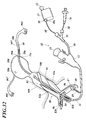
- FIG. 18 is a perspective view of the endoscope system 1C. Parts corresponding to each other between the endoscope system 1C in the fourth embodiment and the endoscope system 1 in the first embodiment are denoted by the same reference numerals. The difference between the endoscope system 1C in the fourth embodiment and the endoscope system 1 in the first embodiment resides in the catheter 58 and the liquid delivery device 70. That is, the endoscope system 1C does not include the catheter 58 and the liquid feeding device 70.
- the second input port 55c is blocked by a cap or a rubber plug.
- a port adapter 19 is attached to the opening of one end 18a of the channel 18.
- the port adapter 19 is provided with a valve mounting portion 19a, and various valves can be mounted on the valve mounting portion 19a.
- the port adapter 19 is provided with an inlet port 19b, and the inlet port 19b is connected to a syringe, a pump, a perfusion system, or an infusion bag via a tube.
- portions corresponding to each other between the endoscope system 1C in the fourth embodiment and the endoscope system 1 in the first embodiment are similarly provided.
- the liquid is supplied from the distal end of the catheter 50 by supplying the liquid to the catheter 50 by the liquid feeding device 70.
- the liquid is supplied to the channels 18 and 17 by a syringe, a pump, a perfusion system, or an infusion bag, and then from the distal end of the channel 17. Spout liquid.
- the distal portion of the catheter 50 and the distal portion 40c of the insertion portion 40 are wetted by the liquid.
- the method of using the endoscope system 1C in the fourth embodiment is the same as the method of using the endoscope system 1 in the first embodiment.
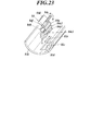
- vaginal opening device 80 when the insertion part 40 of the endoscope system 1C in the fourth embodiment is introduced into the vagina 999 and the uterus 998, a vaginal opening device 80 (see FIG. 21) described later may be used (the vaginal opening device 80). And the sixth to ninth embodiments for the usage thereof).
- FIG. 19 is a perspective view of the endoscope system 1D.
- FIG. 20 is a diagram illustrating a usage state of the endoscope system 1D. Parts corresponding to each other between the endoscope system 1D in the fifth embodiment and the endoscope system 1 in the first embodiment are denoted by the same reference numerals.
- the first endoscope 10 is different from the endoscope system 1D in the fifth embodiment and the endoscope system 1 in the first embodiment. That is, in the endoscope system 1, the first endoscope 10 is a flexible endoscope, whereas in the endoscope system 1D, the first endoscope 10 is a rigid endoscope. That is, in the endoscope system 1D, the insertion portion 11 of the first endoscope 10 is rigid, and the insertion portion 11 is not curved. Further, the first endoscope 10 of the endoscope system 1D has a perfusion system.
- the endoscope system 1D does not include the second catheter 50, the hemostasis valve 55, the catheter 58, and the liquid feeding device 70. This is the same as the endoscope system 1A in the second embodiment.
- portions corresponding to each other between the endoscope system 1D in the fifth embodiment and the endoscope system 1 in the first embodiment are similarly provided.
- the usage method of the endoscope system 1D in the fifth embodiment is substantially the same as the usage method of the endoscope system 1 in the first embodiment.
- the point that the method of using the endoscope system 1D in the fifth embodiment differs from the method of using the endoscope system 1 in the first embodiment will be mainly described.
- an operator When using the endoscope system 1D in the fifth embodiment, an operator first performs a laparotomy or a laparoscopic operation, inserts the insertion portion 11 into the uterus 998, and moves the distal end 11a of the insertion portion 11 to the distal end 11a. Lightly abut the fallopian opening 996 or insert the distal end 11a into the fallopian opening 996. Then, the operator causes the insertion portion 40 attached to the holding portion 31 to enter the channel 17, slightly protrudes the distal end 40 b of the insertion portion 40 from the distal end of the channel 17, and Insert the end 40b slightly into the fallopian tube 996 of the fallopian tube 997. Then, the operator temporarily stops the insertion portion 40 (see FIG. 20).
- the liquid is fed by the perfusion system, and the liquid is ejected from the distal end of the channel 17. This fills the oviduct 997 with liquid.
- the operator further inserts the insertion portion 40 into the channel 17 and introduces the distal end 40 b of the insertion portion 40 to the fallopian tube 995.
- the operator observes and diagnoses the fallopian tube 997 and / or the fallopian tube 995 as the operator peeks into the eyepiece optical system 33 of the eyepiece 32 while further inserting the insertion portion 40 into the channel 17.
- the operator pulls out the insertion portion 40 from the channel 17, pulls out the distal end 40 b of the insertion portion 40 from the oviduct 997, and pulls the distal end 40 b of the insertion portion 40 into the channel 17.
- liquid may be blown out of the distal end of the channel 17 by the perfusion system and injected or refilled into the fallopian tube 997.
- the operator removes the distal end 11 a of the insertion portion 11 from the fallopian tube opening 996 of the fallopian tube 997 and pulls out the insertion portion 11 from the uterus 998. Then, the operator performs suturing of the abdomen.
- the insertion portion 40 is pulled out from the channel 17. Then, the proximal end 40a of the insertion part 40 is removed from the holding part 31, and the insertion part 40 is discarded.
- the insertion portion 11 and the insertion portion 40 may be inserted from the fallopian tube 995 into the fallopian tube 997.
- FIG. 21 is a perspective view of an endoscope system (oviduct scope guide device) 1E.
- FIG. 22 is a view showing a use state of the endoscope system 1E. Parts corresponding to each other between the endoscope system 1E in the sixth embodiment and the endoscope system 1 in the first embodiment are denoted by the same reference numerals.
- This endoscope system 1E includes a first endoscope 10, a second endoscope 30, a catheter 50, a hemostasis valve 55, and a liquid feeding device 70, similarly to the endoscope system 1 in the first embodiment.
- the first endoscope 10, the second endoscope 30, the catheter 50, the hemostasis valve 55, and the liquid feeding device 70 in the sixth embodiment are the same as the first endoscope 10 and the second endoscope in the first embodiment. 30, the catheter 50, the hemostasis valve 55, and the liquid delivery device 70.
- the endoscope system 1E further includes an ultrasonic probe 100 (see FIG. 22).
- the ultrasonic probe 100 is connected to the main body of the ultrasonic diagnostic apparatus.
- the ultrasonic probe 100 outputs ultrasonic waves and inputs ultrasonic echoes from the outside of the ultrasonic probe 100.
- the difference between the endoscope system 1E in the sixth embodiment and the endoscope system 1 in the first embodiment resides in the vaginal opening device 80.
- This vaginal opening device 80 is provided with holders (holding tools 84 and 86).
- holders holding tools 84 and 86.
- the vaginal opening device 80 will be described in detail.
- the opening device 80 includes a first blade 81, a second blade 82, a first holder (holder) 84, a second holder (holder) 86, a first handle 87, a second handle 88, a screw 89, a fixing device 90, and It has a joint pin 91 and the like.
- a first blade (lower blade) 81 and a second blade (upper blade) 82 are connected by a joint pin 91 so as to be opened and closed.
- the first blade 81 has a blade body 81a and a handle 81b.
- a handle portion 81b is provided at the base of the blade body portion 81a, and the blade body portion 81a and the handle portion 81b are integrally formed.
- the handle part 81b is bent from the base part of the blade body part 81a.
- the first handle 87 is connected to the base of the blade body 81a at the inner angle formed by the handle portion 81b and the blade body 81a, and the first handle 87 and the first blade 81 are integrally formed.
- a first handle 87 extends from the base of the blade body 81a.
- the second blade 82 has a blade body 82a and a handle 82b.
- a handle 82b is provided at the base of the blade body 82a, and the handle 82b and the blade body 82a are integrally formed.
- the handle part 82b is bent from the base part of the blade body part 81a.
- the second handle 88 is connected to the base of the blade body 81a at the outer angle formed by the handle 82b and the blade body 82a, and the second handle 88 and the blade body 82a are integrally formed.
- a second handle 88 extends from the base of the blade body 82a.
- An opening 88a is formed in the base of the second handle 88 and the base of the blade body 82a, and the first blade 81 is passed through the opening 88a.
- the base of the blade body 81 a and the base of the blade body 82 a are rotatably connected by a joint pin 91.
- the blade main body 81a and the blade main body 82a are provided to be openable and closable.
- the blade main body portions 81 a and 82 a, the handle portions 81 b and 82 b, the first handle 87, and the second handle 88 are arranged radially around the joint pin 91. More specifically, the handle 81b extends radially outward from the base of the blade body 81a with the joint pin 91 as the center, and the handle 81b is separated from the blade body 82a by the blade body 81a. Thus, it is bent from the base of the blade body 81a in the opposite direction to the opening direction.
- the handle portion 82b extends radially outward from the base portion of the blade main body portion 82a with the joint pin 91 as the center, and the handle portion 82b opens in such a way that the blade main body portion 82a is separated from the blade main body portion 81a. Is bent from the base of the blade body 82a in the opposite direction.
- the first handle 87 extends outward in the radial direction around the joint pin 91 from the inner angle formed by the handle portion 81b and the blade body portion 81a.
- the second handle 88 extends outward in the radial direction around the joint pin 91 from an outer angle formed by the handle portion 82b and the blade body portion 82a.
- a first handle 87, a second handle 88, a handle portion 81b, a handle portion 82b, a blade body portion 82a, and a blade body portion 81a are arranged in this order along the circumferential direction around the joint pin 91. Is between the handle portion 81b and the first handle 87, and the first handle 87 is between the second handle 88 and the blade body 81a.
- the blade body 81a and the blade body 82a are provided in a bowl shape.
- the mutually facing surfaces of the blade body 81a and the blade body 82a are provided in a concave shape, and the surfaces of the blade body 81a and the blade body 82a that are opposite to each other are formed in a convex shape.
- the handle portion 81b and the handle portion 82b are provided in a semi-tubular shape.
- the mutually facing surfaces of the handle portion 81b and the handle portion 82b are provided in a cylindrical concave shape, and the surfaces of the handle portion 81b and the handle portion 82b that are opposite to each other are provided in a cylindrical convex shape.
- An opening 88b is formed at the tip of the second handle 88, and the opening 88b penetrates the second handle 88 in the circumferential direction around the joint pin 91.
- the screw 89 is passed through the opening 88 b, and the proximal end portion of the screw 89 is attached to the distal end portion of the first handle 87.
- a first holder 84 is provided on the handle portion 81b, and a second holder 86 is provided on the handle portion 82b.
- the first holder 84 is provided on the surface of the handle portion 81b on the handle portion 82b side
- the second holder 86 is provided on the handle portion 82b on the surface of the handle portion 81b side.
- the first holding tool 84 and the second holding tool 86 face each other in the circumferential direction around the joint pin 91.
- the first holder 84 may be detachable with respect to the handle portion 81b or may not be detachable. The same applies to the second holder 86 and the handle portion 82b.
- the first holder 84 may be attached to the handle portion 81b and fixed to the handle portion 81b, or may be formed integrally with the handle portion 81b. The same applies to the second holder 86 and the handle portion 82b.
- the first holding tool 84 holds the first endoscope 10 (particularly, the insertion portion 11), grasps, pinches, grips, picks, inserts, engages, engages, engages, hooks, or By locking, the first endoscope 10 is held. The same applies to the second holder 86.
- FIG. 23 is a perspective view showing the first holder 84 that can be attached to and detached from the handle portion 81b together with the handle portion 81b.
- the first holder 84 is a clip (pinch).
- the first holder 84 includes sandwiching pieces 84a and 84b, knobs 84c and 84d, a base 84e, and a hinge coupling portion 84f.
- the clamping pieces 84a and 84b are hinged so that they can be opened and closed, and the clamping pieces 84a and 84b are closed by the elastic force of the hinge coupling portion 84f (see the direction of the arrow b).
- a pinch 84c is provided on the pinching piece 84a, and a pinch 84d is provided on the pinching piece 84b.
- the pinching pieces 84a and 84b are open. If the insertion portion 11 of the first endoscope 10 is inserted between the holding pieces 84a and 84b and the knobs 84c and 84d are released, the holding pieces 84a and 84b are closed (see the direction of the arrow b), The insertion portion 11 of the first endoscope 10 is sandwiched between the sandwiching pieces 84c and 84d.
- the direction in which the blade body portions 81a and 82a and the insertion portion 11 are inserted into the vagina 999 is perpendicular to the direction in which the clamping pieces 84a and 84b open and close.
- Pedestals 84e1 and 84e2 are provided at the lower end of the sandwiching piece 84b.
- the pedestals 84e1 and 84e2 are provided in a rectangular plate shape, and the notch 84e3 is formed in the pedestal 84e1, but the notch is not formed in the pedestal 84e2.
- an attachment hole 81c is formed in the handle portion 81b.
- the mounting hole 81c includes a fitting portion 81d that fits the shape of the pedestal 84e1 and has a smaller area than the pedestal 84e2, and a fastening portion 81e that is integrated with the fitting portion 81d and extends from the fitting portion 81d.
- the pedestal 84e1 is passed through the fitting portion 81d of the mounting hole 81c from the inside of the handle portion 81b to the outside of the handle portion 81b, and is hooked on the handle portion 81b around the portion 81d into which the pedestal 84e2 is fitted. Then, by sliding the first holder 84 from the fitting portion 81d to the fastening portion 81e, the handle portion 81b is sandwiched between the pedestal 84e1 and the pedestal 84e2, and the pedestals 84e1 and 84e2 are arranged around the fastening portion 81e. I get caught in 81b. Thereby, the 1st holder 84 can be attached to the handle
- FIG. 24 is a perspective view showing the first holder 84 that cannot be removed from the handle portion 81b together with the handle portion 81b.
- the first holder 84 is a clip (pinch).
- the first holder 84 has clamping pieces 84g and 84h and a hinge coupling portion 84i.
- the holding piece 84g is formed on the handle portion 81b so as to protrude inward from the inner surface of the handle portion 81b, and the holding piece 84g is formed integrally with the handle portion 81b.
- An attachment hole is formed in the handle portion 81b along the holding piece 84g, and a holding piece 84h is inserted into the attachment hole.
- the sandwiching piece 84h protrudes to both the inside and the outside of the handle portion 81b, and the sandwiching piece 84h is hinged to the handle portion 81b by a hinge coupling portion 84i on the outside of the handle portion 81b.
- the hinge coupling portion 84i is provided with an elastic member, and the elastic member urges the holding piece 84h in the direction of arrow c, and the holding pieces 84g and 84h are closed by the elastic force of the elastic member.
- the holding pieces 84g and 84h can be opened and closed by swinging the holding pieces 84h (particularly, the portion protruding outside the handle portion 81b).
- the sandwiching pieces 84g and 84h are opened. If the insertion portion 11 of the first endoscope 10 is inserted between the holding pieces 84g and 84h and the holding piece 84h (particularly, the portion protruding outside the handle portion 81b) is released, the holding piece 84g , 84h are closed (refer to the direction of arrow c), and the insertion portion 11 of the first endoscope 10 is sandwiched between the sandwiching pieces 84g, 84h.
- FIG. 25 is a perspective view showing the fitting type first holder 84 together with the handle portion 81b.
- the first holder 84 is formed on the handle portion 81b so as to protrude inward from the inner surface of the handle portion 81b.
- the first holding tool 84 is formed in a U-shaped cross section, a V-shaped cross section, a U-shaped cross section, a cross-sectional gate shape, or a cross-sectional bow, and the first holding tool 84 has a fitting groove 84j. Is recessed. By inserting the insertion portion 11 of the first endoscope 10 into the fitting groove 84j, the insertion portion 11 is held by the first holder 84.
- FIG. 26 is a perspective view showing a vise-type first holder 84 together with a handle portion 81b.
- the first holder 84 includes a screw 84k, a knob 84m, and a main body 84n.
- the main body 84n is formed in a U-shaped cross section, a U-shaped cross section, a gate shape in a cross section, or a cross section bow, and the main body 84n is provided inside the handle portion 81b. That is, the main body 84n has a bottom portion 84p fixed to the inner surface of the handle portion 81b, a fixed clamping piece 84q provided at one end in the width direction of the bottom portion 84p, and the other end in the width direction of the bottom portion 84p.
- a support piece 84r provided in the above state.
- a screw hole is formed in the side surface of the handle portion 81b and the support piece 84r, and the screw 84k is screwed into the screw hole.
- a cushion material (for example, rubber) is provided at the distal end of the screw 84k inside the handle portion 81b, and a knob 84m is provided at the proximal end of the screw 84k outside the side surface of the handle portion 81b.
- the insertion portion 11 of the first endoscope 10 is sandwiched between the distal end of the first endoscope 10 and the fixed clamping piece 84q.
- the knob 84m and the screw 84k are rotated in the opposite direction, the insertion portion 11 of the first endoscope 10 can be released.
- the second holder 86 can have the same configuration as the first holder 84 shown in FIGS.
- portions corresponding to each other between the endoscope system 1E in the sixth embodiment and the endoscope system 1 in the first embodiment are similarly provided.
- An operator such as a doctor assembles the insertion portion 40, the catheter 50, the hemostasis valve 55, and the catheter 58. That is, the proximal end of the catheter 50 is connected to the output port 55a of the hemostasis valve 55, one end of the catheter 58 is connected to the second input port 55c of the hemostasis valve 55, and the distal end 40b of the insertion portion 40 is connected to the hemostasis valve 55.
- the insertion portion 40, the catheter 50, the hemostasis valve 55, and the catheter 58 may be assembled in advance.
- the proximal end 40 a of the insertion portion 40 is attached to the holding portion 31, and the proximal end 40 a of the insertion portion 40 is fixed to the holding portion 31 by the positioning mechanism 36.
- the distal end 40 b of the insertion portion 40 is aligned with the distal end of the catheter 50 by moving the insertion portion 40 forward or backward, or the distal end 40 b of the insertion portion 40 is pulled into the catheter 50. Further, the catheter 58 is connected to the liquid feeding device 70, and a liquid such as a sterilizing solution is supplied to the liquid feeding device 70.
- the opening of one end 18a of the channel 18 is closed with a cap or the like, or the port adapter 19 is attached to the opening.
- a valve is attached to the valve attachment portion 19a, and a syringe, a pump, a perfusion system or an infusion bag is connected to the inlet port 19b.
- a liquid such as a sterilizing solution is supplied to the syringe.
- a liquid such as a sterilizing liquid is supplied to a tank (liquid supply source) of a pump or a perfusion system. Liquid such as sterilization liquid is stored in the drip bag.
- the operator inserts the catheter 50 together with the insertion portion 40 into one end (proximal end) of the channel 17, and the distal end 40 b of the insertion portion 40 and the distal end of the catheter 50 are connected to the other end (distant end) of the channel 17.
- the insertion portion 40 and the catheter 50 are advanced into the channel 17 so as not to come out from the distal end.
- the operator rotates the fixing tool 90, moves the fixing tool 90 to the tip end side of the screw 89, and closes the blade main body portions 81a and 82a.
- the operator opens the vaginal opening and the vagina 999 with the opening device 80. Specifically, the tips of the blade main body portions 81a and 82a are inserted into the vaginal opening, the blade main body portions 81a and 82a are inserted into the vagina 999, and then the blade main body portions 81a and 82a are opened. It is opened by the main body portions 81a and 82a.
- the second handle 88 When opening the blade main body portions 81 a and 82 a, the second handle 88 is pushed by the fixture 90 by rotating the fixture 90 and moving the fixture 90 toward the proximal end of the screw 89. As a result, the handles 87 and 88 approach each other, the handle portions 81b and 82b approach each other, and the blade body portions 81a and 82a open. By opening the blade main body portions 81a and 82a, the opening device 80 is naturally fixed to the vaginal opening.
- the operator After opening the vaginal opening and vagina 999, the operator inserts the insertion portion 11 into the blade body 81a, 82a from the opening 88a of the vaginal opening 80, and introduces the insertion portion 11 into the vagina 999 and the uterus 998 in this order. To do. Since the vagina 999 is opened by the vaginal opening device 80, the insertion portion 11 can be easily introduced into the vagina 999 and the uterus 998. Even if the blade body portions 81 a and 82 a are opened and the handle portions 81 b and 82 b are closed, the blades 81 and 82 are bent, so that the holders 84 and 86 do not hinder insertion of the insertion portion 11.
- the illumination light source 16 When the insertion unit 11 is introduced, since the illumination light source 16 is turned on, the illumination light emitted from the illumination light source 16 is guided to the illumination unit 15 by an optical fiber or an optical fiber bundle, and the illumination light is emitted from the illumination unit 15. The On the other hand, since the image in front of the illumination unit 15 is captured by the image input unit 14, the operator can perform observation and diagnosis in front of the image input unit 14 by looking into the eyepiece unit 13. The operator introduces the insertion portion 11 into the vagina 999 and the uterus 998 while performing such observation and diagnosis.
- the operator operates the holding portion 12 to bend the distal portion 11 b of the insertion portion 11 and direct the distal end 11 a of the insertion portion 11 toward the fallopian tube opening 996 of the fallopian tube 997. Then, the operator operates the holding portion 12 to bring the distal end 11a of the insertion portion 11 closer to the fallopian tube opening 996, and presses the distal end 11a against the fallopian tube opening 996 with an appropriate load. 11, so that the distal end 11 a of the eleven is not separated from the fallopian tube 996. At this time, the distal end 11a of the insertion portion 11 may be slightly inserted into the fallopian tube opening 996.
- the fallopian tube 996 refers to the end of the fallopian tube 997 that opens in the inner wall of the uterus 998.
- the ultrasonic probe 100 of the ultrasonic diagnostic apparatus may be applied to the abdomen of the patient and the inside of the uterus 998 may be observed by the ultrasonic diagnostic apparatus. Thereby, the position and orientation of the distal end 11a of the insertion portion 11 can be confirmed by the ultrasonic diagnostic apparatus. Similarly, when the distal end 11a of the insertion portion 11 is applied to the fallopian tube 996, the inside of the uterus 998 may be observed by an ultrasonic diagnostic apparatus.
- the insertion portion 40 of the second endoscope 30 can be easily moved to the fallopian tube 997. I can guide you.
- the proximal portion of the insertion portion 11 is attached to the first holder 84, and the insertion portion 11 is fixed to the vagina device 80.
- the distal end 11a of the insertion portion 11 is biased in the direction to be inserted into the oviduct 997, and the state where the distal end 11a of the insertion portion 11 is applied to the oviduct opening 996 with an appropriate load is maintained.
- the insertion portion 11 is held in a stretched state.
- the insertion part 11 of the 2nd endoscope 30 and the 1st endoscope 10 can be maintained in the stable state.
- the first endoscope 10 when the first endoscope 10 is fixed, it is possible to save the operator from having to work with the first endoscope 10 and to reduce the burden on the operator. Furthermore, a work space can be secured.
- the proximal portion of the insertion portion 11 may be held by the second holder 86.
- the operator enters the catheter 50 into the channel 17, the distal end of the catheter 50 protrudes from the distal end of the channel 17, and the distal end of the catheter 50 is slightly moved to the fallopian tube 996 of the fallopian tube 997. Insert into.
- the liquid is fed by the liquid feeding device 70 as necessary, and the liquid flows inside the channel 17 and inside the catheter 50. And the liquid is ejected from the distal end of the catheter 50. Then, the distal portion 50a of the catheter 50 can be easily slipped with respect to the fallopian tube 997 by the liquid, and the distal end of the catheter 50 can be easily inserted into the fallopian tube 997. Even if the liquid is supplied to the hemostasis valve 55 by the liquid feeding device 70, the check valve is provided in the first input port 55b, so that the liquid does not leak from the first input port 55b.
- the ultrasonic oscillator 35 when the distal end of the catheter 50 is protruded from the distal end of the channel 17, the ultrasonic wave is propagated to the distal end 40 b of the insertion portion 40 by the ultrasonic transmission member 43.
- the distal end of the catheter 50 is ultrasonically vibrated together with the distal end 40b of the insertion portion 40. Therefore, it becomes easy to insert the distal end of the catheter 50 into the oviduct 997.
- the ultrasound probe 100 of the ultrasound diagnostic apparatus is applied to the abdomen of the patient, and the fallopian tube 997 is observed by the ultrasound diagnostic apparatus. Good. Thereby, the position and protrusion length of the distal end of the catheter 50 can be confirmed by the ultrasonic diagnostic apparatus.
- the liquid is fed by the liquid feeding device 70, and the liquid is ejected from the distal end of the catheter 50.
- the ejected liquid is filled in the oviduct 997.
- the fallopian tube becomes straight, and the insertion portion 40 can be easily introduced.
- surroundings of the distal end 40b of the insertion part 40 are satisfy
- the liquid is supplied to the channels 18, 17 by a syringe, a pump, a perfusion system, or an infusion bag together with the liquid feeding by the liquid feeding device 70. May be supplied.
- the liquid is supplied to the channels 18 and 17, the liquid is ejected from the distal end of the channel 17.
- the distal portion of the catheter 50 and the distal portion 40c of the insertion portion 40 are wetted by the liquid.
- the operator causes the insertion portion 40 to enter the catheter 50, the distal end 40 b of the insertion portion 40 protrudes from the distal end of the catheter 50, and the distal end 40 b of the insertion portion 40 is inserted into the oviduct 997. . Then, the operator further inserts the insertion portion 40 into the catheter 50 and introduces the distal end 40b of the insertion portion 40 as far as possible into the deepest of the fallopian tube 997, up to the fallopian tube 995.
- the liquid in the fallopian tube 997 (liquid ejected from the catheter 50) wets well with the hydrophilic portion 47 of the insertion portion 40, and the liquid is not repelled from the hydrophilic portion 47, A slime is generated on the surface of the hydrophilic portion 47. Accordingly, the distal portion 40c of the insertion portion 40 is easily slipped with respect to the fallopian tube 997 by the liquid, and the distal end 40b of the insertion portion 40 is easily introduced into the fallopian tube 997 and the fallopian tube 995.
- a liquid may be fed by the liquid feeding device 70, and the liquid may be injected or supplemented into the fallopian tube 997.
- Either the step of inserting the insertion portion 40 into the oviduct 997 or the step of blowing the liquid from the distal end of the catheter 50 by the liquid delivery device 70 may be performed first, or these steps may be performed simultaneously.
- a guide wire is inserted into the fallopian tube, then a catheter is inserted into the fallopian tube using the guidewire, then the guidewire is pulled out, and then the catheter is used.
- the oviduct scope was inserted into the oviduct.
- the ultrasonic oscillator 35 When inserting the distal end 40b of the insertion portion 40 into the fallopian tube 997 or the fallopian tube 995 or both, if the ultrasonic oscillator 35 is activated, the ultrasonic wave is transmitted to the distal end of the insertion portion 40 by the ultrasonic transmission member 43. Propagating to the end 40b, the distal end 40b of the insertion portion 40 vibrates ultrasonically. It becomes easy to insert the distal end 40 b of the insertion portion 40 into the oviduct 997.
- the illumination light source 34 When the insertion portion 40 is inserted, the illumination light source 34 is turned on, so that the illumination light emitted from the illumination light source 34 is guided to the distal end of the second optical fiber bundle 42 by the second optical fiber bundle 42, Illumination light is emitted from the distal end of the second optical fiber bundle 42.
- an image in front of the distal end 40 b of the insertion portion 40 is taken into the distal end of the first optical fiber bundle 41, and the image is transmitted to the proximal end by the first optical fiber bundle 41. Therefore, the operator can observe and diagnose the fallopian tube 997 or fallopian tube 995 or both by looking into the eyepiece optical system 33 of the eyepiece 32. The operator introduces the insertion portion 40 into the fallopian tube 997 while performing such observation and diagnosis.
- the ultrasonic probe 100 of the ultrasonic diagnostic apparatus may be applied to the abdomen of the patient, and the fallopian tube 997 may be observed by the ultrasonic diagnostic apparatus. Thereby, the insertion amount of the insertion part 40 and the position of the distal end 40b of the insertion part 40 can be confirmed by the ultrasonic diagnostic apparatus.
- the operator pulls out the insertion portion 40 from the catheter 50 and pulls out the distal end 40b of the insertion portion 40 from the fallopian tube 997.
- the liquid may be blown out from the distal end of the catheter 50 by the liquid feeding device 70 to inject or replenish the liquid into the oviduct 997.
- an operator may observe and diagnose the fallopian tube 997 and / or fallopian tube 995 by looking into the eyepiece optical system 33 of the eyepiece part 32.
- the operator pulls out the catheter 50 from the channel 17, pulls out the distal end of the catheter 50 from the fallopian tube 996, and pulls the distal end of the catheter 50 into the channel 17.
- the operator removes the insertion portion 11 from the first holder 84. Then, the operator operates the holding portion 12 to pull out the insertion portion 11 from the uterus 998 and the vagina 999 while straightening the distal portion 11 b of the insertion portion 11.
- the proximal end 40 a of the insertion portion 40 is removed from the holding portion 31, and the catheter 58 is removed from the liquid delivery device 70. And the insertion part 40, the catheter 50, the hemostasis valve
- FIG. 27 is a perspective view of an endoscope system (oviduct scope guide device) 1F.
- FIG. 28 is a diagram showing a use state of the endoscope system 1F. Portions corresponding to each other between the endoscope system 1F in the seventh embodiment and the endoscope system 1E in the sixth embodiment are denoted by the same reference numerals.
- the difference between the endoscope system 1F in the seventh embodiment and the endoscope system 1E in the sixth embodiment resides in the catheter 50, the hemostasis valve 55, the catheter 58, and the liquid feeding device 70. That is, the endoscope system 1F does not include the catheter 50, the hemostasis valve 55, the catheter 58, and the liquid feeding device 70.
- the first endoscope 10 has a port adapter 19 attached to the opening of one end 18a of the channel 18, and a syringe, a pump, a perfusion system, or an infusion bag is connected to the port adapter 19 via a tube. Connected to the inlet port 19b.
- portions corresponding to each other between the endoscope system 1F in the seventh embodiment and the endoscope system 1E in the sixth embodiment are similarly provided.
- the usage method of the endoscope system 1F in the seventh embodiment is almost the same as the usage method of the endoscope system 1E in the sixth embodiment.
- a method of using the endoscope system 1F in the seventh embodiment will be described.
- the proximal end 40a of the insertion portion 40 is first attached to the holding portion 31, and the proximal end 40a of the insertion portion 40 is fixed to the holding portion 31 by the positioning mechanism 36.
- the operator inserts the insertion portion 40 into one end (proximal end) of the channel 17 so that the distal end 40b of the insertion portion 40 does not protrude from the other end (distal end) of the channel 17.
- 40 enters channel 17.
- the insertion portion 40 is inserted into the channel 17 by passing the insertion portion 40 through a valve (for example, a check valve), packing or a plug (for example, a plug described in Japanese Utility Model Publication No. 55-70108).
- a valve for example, a check valve
- packing or a plug for example, a plug described in Japanese Utility Model Publication No. 55-70108.
- the valve, the packing, the plug, or the like may be fitted into the opening at the proximal end of the channel 17.
- the operator opens the vaginal opening and vagina 999 with the vaginal opening device 80, inserts the insertion portion 11 into the opening vaginal device 80, and determines the position and orientation of the distal end 11a of the insertion portion 11 by an ultrasonic diagnostic apparatus.
- the insertion part 11 is introduced into the vagina 999 and the uterus 998 in this order while confirming.
- illumination light is emitted from the illumination unit 15 by turning on the illumination light source 16, and the operator peeks into the eyepiece unit 13, and in front of the image input unit 14 (vagina 999 and uterus 998). Observe and diagnose.
- the operator operates the holding portion 12 while confirming the position and orientation of the distal end 11a of the insertion portion 11 with an ultrasonic diagnostic apparatus, thereby bending the portion 11b on the distal side of the insertion portion 11,
- the distal end 11a of the insertion portion 11 is directed toward the fallopian tube opening 996 of the fallopian tube 997, and the distal end 11a of the insertion portion 11 is pressed against the fallopian tube opening 996.
- a liquid may be fed by a syringe, a pump, a perfusion system, or an infusion bag, and the liquid may be ejected from the distal end of the channel 17. If a valve, packing, plug or the like is fitted in the opening at the proximal end of the channel 17, the liquid supplied to the channel 17 can be prevented from being ejected from the proximal end of the channel 17.
- the proximal portion of the insertion portion 11 is attached to the first holder 84, and the distal end 11a of the insertion portion 11 is kept in a state of being applied to the fallopian tube 996 with an appropriate load.
- the operator enters the insertion portion 40 into the channel 17 while confirming the distal end 40b and the like of the insertion portion 40 with an ultrasonic diagnostic apparatus, and the distal end 40b of the insertion portion 40 is moved from the distal end of the channel 17. It protrudes slightly and the distal end 40b of the insertion part 40 is inserted a little into the fallopian tube 996 of the fallopian tube 997. Then, the worker temporarily stops the insertion portion 40 from entering.
- a liquid is sent to the channel 17 by a syringe, a pump, a perfusion system, or an infusion bag, and the liquid is ejected from the distal end of the channel 17.
- the fallopian tube becomes straight, and the insertion portion 40 can be easily introduced.
- surroundings of the distal end 40b of the insertion part 40 are satisfy
- the operator further moves the insertion portion 40 into the channel 17 while confirming the distal end 40b and the like of the insertion portion 40 using an ultrasonic diagnostic apparatus, and the distal end 40b of the insertion portion 40 is moved up to the fallopian tube 995 at the maximum.
- the liquid in the oviduct 997 (liquid ejected from the channel 17) is well wetted by the hydrophilic portion 47 of the insertion portion 40, and the liquid is not repelled from the hydrophilic portion 47, so that the surface of the hydrophilic portion 47 is not smooth. Arise. Therefore, it becomes easy to introduce the distal end 40b of the insertion portion 40 into the oviduct 997.
- a liquid When inserting the insertion portion 40 into the fallopian tube 997, a liquid may be fed by a syringe, a pump, a perfusion system, or an infusion bag, and the liquid may be injected or replenished into the fallopian tube 997.
- the ultrasonic oscillator 35 When inserting the distal end 40b of the insertion portion 40 into the oviduct 997, the ultrasonic oscillator 35 may be activated.
- the operator observes and diagnoses the fallopian tube 997 and / or the fallopian tube 995 as the operator peeks into the eyepiece optical system 33 of the eyepiece 32 while further inserting the insertion portion 40 into the channel 17.
- the operator pulls out the insertion portion 40 from the channel 17, pulls out the distal end 40 b of the insertion portion 40 from the oviduct 997, and pulls the distal end 40 b of the insertion portion 40 into the channel 17.
- liquid may be blown out of the distal end of the channel 17 by the perfusion system and injected or refilled into the fallopian tube 997.
- the operator removes the insertion portion 11 from the first holder 84. Then, the operator operates the holding portion 12 to remove the distal end 11a of the insertion portion 11 from the fallopian tube opening 996 of the fallopian tube 997 and insert while straightening the distal portion 11b of the insertion portion 11. Part 11 is withdrawn from uterus 998 and vagina 999.
- the insertion portion 40 is pulled out from the channel 17.
- the proximal end 40a of the insertion portion 40 is removed from the holding portion 31, and the insertion portion 40 is discarded.
- FIG. 29 is a perspective view of an endoscope system (oviduct scope guide device) 1G. Parts corresponding to each other between the endoscope system 1G in the eighth embodiment and the endoscope system 1E in the sixth embodiment are denoted by the same reference numerals.
- the difference between the endoscope system 1G in the eighth embodiment and the endoscope system 1E in the sixth embodiment resides in the catheter 50. That is, the endoscope system 1G does not have the catheter 50.
- the output port 55a of the hemostasis valve 55 is connected to the opening of one end (proximal end) of the channel 17. Specifically, the output port 55a of the hemostasis valve 55 is directly screwed into, engaged with, or fitted to the opening at one end of the channel 17. Alternatively, the output port 55a of the hemostasis valve 55 is connected to the opening at one end of the channel 17 by a joint (for example, a luer lock).
- a joint for example, a luer lock
- the output port 55a of the hemostasis valve 55 is connected to the luer lock, and the luer lock is connected to the opening at one end of the channel 17, or the output port 55a of the hemostasis valve 55 is connected to the adapter.
- the adapter is threadedly engaged with, or engaged with, the luer lock, and the luer lock is connected to the opening at one end of the channel 17.
- portions corresponding to each other are similarly provided between the endoscope system 1G in the eighth embodiment and the endoscope system 1E in the sixth embodiment.
- the method of using the endoscope system 1G in the eighth embodiment is almost the same as the method of using the endoscope system 1E in the sixth embodiment.
- a method of using the endoscope system 1G in the eighth embodiment will be described.
- an operator When using the endoscope system 1G, an operator first assembles the insertion portion 40, the catheter 50, and the hemostasis valve 55.
- bulb 55 may be assembled previously.
- the operator connects the catheter 58 to the liquid feeding device 70 and supplies a liquid (for example, a sterilizing solution or physiological saline) to the liquid feeding device 70.
- a liquid for example, a sterilizing solution or physiological saline
- the operator inserts the insertion portion 40 into one end (proximal end) of the channel 17 and connects the output port 55a of the hemostasis valve 55 to one end (proximal end) of the channel 17. Then, the insertion portion 40 is caused to enter the channel 17 so that the distal end 40 b of the insertion portion 40 does not come out of the other end (distal end) of the channel 17.
- the operator opens the vaginal opening and vagina 999 with the vaginal opening device 80, inserts the insertion portion 11 into the opening vaginal device 80, and determines the position and orientation of the distal end 11a of the insertion portion 11 by an ultrasonic diagnostic apparatus.
- the insertion part 11 is introduced into the vagina 999 and the uterus 998 in this order while confirming.
- the operator presses the distal end 11 a of the insertion portion 11 against the oviduct opening 996 by operating the holding portion 12.
- the proximal portion of the insertion portion 11 is attached to the first holder 84, and the distal end 11a of the insertion portion 11 is kept in a state of being applied to the fallopian tube 996 with an appropriate load.
- the operator enters the hemostasis valve 55 and the channel 17 while confirming the distal end 40b and the like of the insertion portion 40 with an ultrasonic diagnostic apparatus, and the distal end 40b of the insertion portion 40 is moved to the channel 17.
- the distal end 40b of the insertion portion 40 is slightly inserted into the fallopian tube opening 996 of the fallopian tube 997.
- the liquid is fed to the channel 17 by the liquid feeding device 70, the liquid is ejected from the distal end of the channel 17, and the oviduct 997 is filled with the liquid.
- the operator further enters the hemostasis valve 55 and the channel 17 while confirming the distal end 40b and the like of the insertion portion 40 with an ultrasonic diagnostic apparatus, and the distal end 40b of the insertion portion 40 is moved to the maximum. Introduce up to 995 of the fallopian tube.
- the distal end 40b of the insertion portion 40 can be easily introduced into the fallopian tube 997 by the hydrophilic portion 47 of the insertion portion 40 and the liquid that gets wet therewith.
- a liquid may be fed by the liquid feeding device 70, and the liquid may be injected or supplemented into the oviduct 997.
- the ultrasonic oscillator 35 may be activated.
- An operator introduces the distal end 40b of the insertion portion 40 into the fallopian tube 997 and the fallopian tube 995, and peeks at the eyepiece optical system 33 of the eyepiece unit 32, thereby observing the fallopian tube 997 or fallopian tube 995 or these tubes. Observe and diagnose both.
- the operator pulls the insertion portion 40, pulls out the distal end 40 b of the insertion portion 40 from the oviduct 997, and pulls the distal end 40 b of the insertion portion 40 into the channel 17. Also when pulling the insertion part 40, an operator observes and diagnoses the fallopian tube 997 or the fallopian tube 995 or both. Further, at this time, the liquid may be blown out from the distal end of the channel 17 by the liquid feeding device 70 to inject or replenish the liquid into the oviduct 997.
- the operator removes the insertion portion 11 from the first holder 84. Then, the operator operates the holding portion 12 to remove the distal end 11a of the insertion portion 11 from the fallopian tube opening 996 of the fallopian tube 997 and insert while straightening the distal portion 11b of the insertion portion 11. Part 11 is withdrawn from uterus 998 and vagina 999. Next, the output port 55 a of the hemostasis valve 55 is removed from the opening of the channel 17, and the insertion portion 40 is pulled out from the channel 17. Further, the proximal end 40 a of the insertion portion 40 is removed from the holding portion 31, and the catheter 58 is removed from the liquid feeding device 70. Then, the insertion portion 40, hemostasis valve 55, and catheter 58 are discarded.
- FIG. 31 is a perspective view of an endoscope system (oviduct scope guide device) 1H.
- FIG. 32 is a diagram showing a state in which the endoscope system 1H is used. Portions corresponding to each other between the endoscope system 1H in the ninth embodiment and the endoscope system 1E in the sixth embodiment are denoted by the same reference numerals.
- the endoscope 10 is different from the endoscope system 1H in the ninth embodiment and the endoscope system 1E in the sixth embodiment. That is, the endoscope system 1H does not have the endoscope 10.
- portions corresponding to each other are similarly provided between the endoscope system 1H in the ninth embodiment and the endoscope system 1E in the sixth embodiment.
- the insertion portion 40, the catheter 50, the hemostasis valve 55, and the catheter 58 are first assembled.
- the proximal end 40 a of the insertion portion 40 is attached to the holding portion 31, and the proximal end 40 a of the insertion portion 40 is fixed to the holding portion 31 by the positioning mechanism 36.
- the distal end 40 b of the insertion portion 40 is aligned with the distal end of the catheter 50 by moving the insertion portion 40 forward or backward, or the distal end 40 b of the insertion portion 40 is pulled into the catheter 50. Further, the catheter 58 is connected to the liquid feeding device 70, and a liquid such as a sterilizing solution is supplied to the liquid feeding device 70.
- the operator opens the vaginal opening and the vagina 999 with the opening device 80.
- the operator inserts the distal portion 50 a of the catheter 50 into the open vaginal device 80 and introduces it further into the vagina 999.
- the operator inserts the distal portion 50a of the catheter 50 into the cervix while observing the inside of the vagina 999 through the open mouth device 80, and further introduces it into the uterus 998.
- the operator moves the distal end of the catheter 50 close to the fallopian opening 996 and presses the distal end against the fallopian opening 996 with an appropriate load. Do not leave. At this time, the distal end of the catheter 50 may be inserted into the fallopian tube 996.
- the ultrasonic probe 100 of the ultrasonic diagnostic apparatus is applied to the abdomen of the patient, and the position and orientation of the distal end of the catheter 50 are ultrasonically detected. Check with a diagnostic device.
- the proximal portion of the catheter 50 is attached to the first holder 84, and the catheter 50 is fixed to the vaginal opening device 80. Thereby, the state where the distal end of the catheter 50 is applied to the fallopian tube opening 996 with an appropriate load is maintained.
- the liquid is fed to the catheter 50 by the liquid feeding device 70, the liquid is ejected from the distal end of the catheter 50, and the oviduct 997 is filled with the liquid.
- the operator enters the hemostasis valve 55 and the catheter 50 while confirming the distal end 40b and the like of the insertion portion 40 with an ultrasonic diagnostic apparatus, and the distal end 40b of the insertion portion 40 is moved to the maximum. Introduce up to tubal fistula 995.
- the distal end 40b of the insertion portion 40 can be easily introduced into the oviduct 997 by the hydrophilic portion 47 of the insertion portion 40 and the liquid that gets wet with the hydrophilic portion 47.
- a liquid may be fed by the liquid feeding device 70, and the liquid may be injected or supplemented into the oviduct 997.
- the ultrasonic oscillator 35 may be activated.
- An operator introduces the distal end 40b of the insertion portion 40 into the fallopian tube 997 and the fallopian tube 995, and peeks at the eyepiece optical system 33 of the eyepiece unit 32, thereby observing the fallopian tube 997 or fallopian tube 995 or these tubes. Observe and diagnose both.
- the operator pulls the insertion portion 40 and draws the distal end 40 b of the insertion portion 40 from the oviduct 997 into the catheter 50. Also when pulling the insertion part 40, an operator observes and diagnoses the fallopian tube 997 or the fallopian tube 995 or both. Further, at this time, the liquid may be blown from the distal end of the catheter 50 by the liquid feeding device 70 to inject or replenish the liquid into the oviduct 997.
- the operator removes the catheter 50 from the first holder 84. Then, the operator pulls the catheter 50 and removes the distal end of the catheter 50 from the fallopian tube 996. Next, the operator pulls the catheter 50 out of the uterus 998 and vagina 999. Next, the operator removes the proximal end 40 a of the insertion portion 40 from the holding portion 31 and removes the catheter 58 from the liquid delivery device 70. And the insertion part 40, the catheter 50, the hemostasis valve
- FIG. 32 shows a modification of the endoscope system 1 according to the sixth embodiment.
- the ultrasonic probe 100 may be replaced as shown in FIG.
- the operator When using the ultrasonic probe 100, the operator inserts the insertion portion 11 into the blade body 81 a and 82 a from the opening 88 a of the vaginal opening device 80 and introduces the ultrasonic probe 100 into the vagina 999. At that time, the ultrasonic probe 100 introduced into the vagina 999 is applied to the intima or Douglas fossa of the vagina 999, and the inside of the uterus 998 and the fallopian tube 997 is observed by an ultrasonic diagnostic apparatus. The position and orientation of the distal end 11a of the insertion section 11, the position and orientation of the distal end of the catheter 50, the position and orientation of the distal end 40b of the insertion section 40, and the like can be confirmed by an ultrasonic diagnostic apparatus.
- the ultrasonic probe 100 can be attached to the second holder 86 and the ultrasonic probe 100 can be held by the second holder 86.
- the ultrasonic probe 100 may be held by the first holder 84 and the proximal portion of the insertion portion 11 or the catheter 50 may be held by the second holder 86.
- Modification 2 is applied to any of the first to ninth embodiments described above.
- a spherical body 40 d or an umbrella body 40 f is provided at the distal end 40 b of the insertion portion 40.
- a right side surface 40 g of the umbrella body 40 f in FIG. 33 is a convex surface, and the surface 40 g is a distal end surface of the insertion portion 40.
- the radius of the spherical body 40d and the umbrella body 40f is larger than the radius of the outer periphery of the insertion portion 40.
- the spherical body 40d or the umbrella body 40f is formed integrally with the sheath 46, and the first optical fiber bundle 41 (or its lens) and the second optical fiber bundle 42 (or its lens) are the spherical body 40d in FIG. 33 or FIG. Alternatively, it is exposed on the right surface 40e, 40g of the umbrella body 40f.
- the surfaces of the spherical body 40d and the shade body 40f are subjected to hydrophilic treatment, and a hydrophilic film is formed on the surfaces.
- the entire spherical body 40d and the shade body 40f are made of a hydrophilic material. Note that the spherical body 40d and the shade body 40f may not have hydrophilicity.
- the fallopian tube 997 When the operator inserts the insertion portion 40 into the fallopian tube 997, the fallopian tube 997 is pushed out by the spherical body 40d or the umbrella body 40f. Further, when the operator inserts the insertion portion 40 into the fallopian tube 997, the liquid is transferred from the catheter 50 or the channel 17 to the fallopian tube 997 using the liquid delivery device 70, the syringe, the pump, the perfusion system, or the drip bag. inject. The spherical body 40d or the umbrella body 40f is pushed by the hydraulic pressure of the liquid injected into the fallopian tube 997, and the insertion portion 40 can easily enter the fallopian tube 997.
- Modification 2 may be combined with Modifications 3 to 9 described later.
- Modification 3 is applied to any of the first to fourth and sixth to eighth embodiments described above. 35 to 38, the distal end 11a of the insertion portion 11 of the first endoscope 10 is inserted into a cap (attachment) 60, and the cap 60 covers and covers the distal end 11a of the insertion portion 11. ing.
- the cap 60 is detachable from the insertion portion 11.
- the cap 60 is made of a transparent elastic member such as rubber or an opaque elastic member, and a hollow 60 e is formed inside the cap 60.
- the cap 60 has a head 60a, a base 60b, a hollow 60e, a first opening 60d and a second opening 60c.
- the head 60a and the base 60b are integrally formed, and a hollow 60e is formed inside the base 60b and the head 60a.
- the base portion 60b is formed in a cylindrical shape, the head portion 60a is formed in a hollow substantially ball shape, and the head portion 60a bulges radially outward from the base portion 60b.
- a second opening 60c is formed on the top surface of the head 60a, and the second opening 60c communicates with the hollow 60e.
- a first opening 60d is formed in the base end surface of the base 60b, and the first opening 60d communicates with the hollow 60e.
- the cap 60 (head 60a and base 60b) is made of a transparent elastic member, its refractive index is preferably 1.4 to 1.6. That is, the refractive index of the cap 60 is equal to the refractive index of water (1.5) or approximates the refractive index of water.
- the distal end 11a of the insertion portion 11 When using the cap 60, the distal end 11a of the insertion portion 11 is fitted into the first opening 60d on the base 60b side of the cap 60 before the insertion portion 11 is introduced into the uterus 998 (see FIG. 36). At this time, the distal end 11a of the insertion portion 11 is not allowed to reach the head 60a of the cap 60 and the second opening 60c.
- the operator introduces the insertion portion 11 into the uterus 998 together with the cap 60, and the distal end 11a of the insertion portion 11 is moved to the egg. It is brought close to the tube opening 996 (see FIG. 36).
- the second opening 60c is directed to the fallopian tube opening 996, and the hollow 60e is communicated with the fallopian tube opening 996 via the second opening 60c. Since the second opening 60 c is formed in the cap 60, the operator can observe and diagnose the outside of the cap 60 through the second opening 60 c by looking into the eyepiece 13.
- the cap 60 is made of a transparent elastic member, the operator can observe and diagnose the outside of the cap 60 through the cap 60 by looking into the eyepiece 13.
- the head 60a of the cap 60 is pressed against the endometrium around the fallopian tube 996, the head 60a of the cap 60 is compressed in the axial direction (pressing direction) and expanded in the radial direction (see FIG. 37). Accordingly, the cap 60 serves as a lid for the fallopian tube 996, and the fallopian tube 996 is sealed by the cap 60.
- the operator injects the liquid into the oviduct 997 using the liquid delivery device 70, the syringe, the pump, the perfusion system, or the drip bag, and fills the oviduct 997 and the hollow 60e with the liquid. Since the fallopian tube opening 996 is sealed by the cap 60, the liquid in the fallopian tube 997 does not leak into the uterus 998.
- the hollow 60e is filled with the liquid, it is possible to suppress that the image outside the cap 60 looks distorted when the outside of the cap 60 is observed and diagnosed through the cap 60. This is because light at the interface between the cap 60 and the liquid is difficult to be refracted because the refractive index of the liquid and the refractive index of the cap 60 are equal or nearly equal.
- the operator inserts the distal end 40b of the insertion portion 40 into the oviduct 997, and the oviduct 997 and the oviduct cage 995 is observed and diagnosed (see FIG. 38).
- the cap 60 shown in FIGS. 39 and 40 is an improved version of the cap 60 shown in FIGS.
- the head 60a is composed of a one-stage bulge that bulges radially outward.
- the head 60a has a bellows shape, and the head 60a bulges outward in the radial direction in a plurality of stages (three stages in FIG. 21). Consists of outlets 60a1, 60a2, 60a3. The diameters of the bulging portions 60a1, 60a2, and 60a3 are smaller as they are closer to the top of the head and larger as they are closer to the base end. Note that the cap 60 shown in FIGS.
- the 39 and 40 also has a base 60b and a first opening 60d, like the cap 60 shown in FIGS.
- the diameter of the bulging portions 60a1, 60a2, 60a3 is larger than the diameter of the base portion 60b.
- its refractive index is preferably 1.4 to 1.6.
- the cap 60 shown in FIGS. 39 and 40 When the cap 60 shown in FIGS. 39 and 40 is used, the degree of adhesion between the endometrium around the fallopian opening 996 and the bulging portions 60a1, 60a2, 60a3 is improved, and the fallopian opening 996 is more easily sealed ( (See FIG. 40).
- Modification 3 may be combined with Modifications 6 to 9 described later.
- Modification 4 is applied to any of the first to fourth or sixth to eighth embodiments described above. As shown in FIGS. 41 and 42, the distal end 11 a of the insertion portion 11 is inserted into a cap (attachment) 61, and the cap 61 covers the distal end 11 a of the insertion portion 11. A hollow 61 h is formed inside the cap 60. The cap 61 is detachable from the insertion portion 11. The cap 61 is made of a transparent member.
- the refractive index of the cap 61 is preferably 1.4 to 1.6. That is, the refractive index of the cap 61 is equal to the refractive index of water (1.5) or close to the refractive index of water.
- the cap 61 has a base 61b, a head 61a, a hollow 61h, a first opening 61d, and a second opening 61c.
- the base 61b is formed in a cylindrical shape
- the outer peripheral surface of the base 61b is formed in a cylindrical surface
- the inner peripheral surface of the base 61b is formed in a cylindrical surface.
- the head 61a extends from the base 61b so as to be substantially coaxial with the base 61b.
- the head 61a is integrally formed with the base 61b.
- the head 61a is formed in a cylindrical shape
- the outer peripheral surface of the head 61a is formed in a cylindrical surface
- the inner peripheral surface of the head 61a is formed in a cylindrical surface.
- the head 61a is thinner than the base 61b, and the inner diameter of the head 61a is shorter than the outer diameter and inner diameter of the base 61b.
- the corners of the step between the head 61a and the base 61b are rounded, and the step is a smooth step.
- a hollow 61h is formed in the head 61a and the base 61b.
- a second opening 61c is formed in the top surface of the head 61a, and the second opening 61c communicates with the hollow 61h.
- a first opening 61d is formed in the base end surface of the base 61b, and the first opening 61c communicates with the hollow 61h.
- the inner diameter of the base 61b and the diameter of the first opening 61c are longer than the inner diameter of the head 61a and the diameter of the second opening 61d.
- the inner diameter of the base portion 61 b and the diameter of the first opening 61 d are equal to the diameter of the insertion portion 40 or slightly shorter than the diameter of the insertion portion 40.
- the inner diameter of the head 61 a and the diameter of the second opening 61 c are shorter than the diameter of the insertion portion 40.
- the distal end 11a of the insertion portion 11 is inserted into the first opening 61d on the base 61b side of the cap 61 before the insertion portion 11 is introduced into the uterus 998 (see FIG. 42). At this time, since the head portion 61a of the cap 61 is thinner than the base portion 61b, the distal end 11a of the insertion portion 11 does not reach the head portion 61a of the cap 61 and the second opening 61c.
- the operator introduces the insertion portion 11 together with the cap 61 into the uterus 998, and the distal end 11a of the insertion portion 11 is moved to the egg. Move closer to tube 996. Since the cap 61 is transparent, the operator can observe and diagnose the outside of the cap 61 by looking into the eyepiece 13.
- the head 61a of the cap 61 is inserted into the fallopian tube opening 996.
- the cap 61 serves as a lid for the fallopian mouth 996, and the fallopian mouth 996 is sealed by the head 61 a of the cap 61.
- the base 61b of the cap 61 may also be inserted into the fallopian tube 996.
- the operator injects the liquid into the oviduct 997 using the liquid feeding device 70, the syringe, the pump, the perfusion system, or the drip bag, and fills the oviduct 997 and the cap 61 with the liquid. Since the fallopian tube opening 996 is sealed by the head 61 a of the cap 61, the liquid in the fallopian tube 997 does not leak into the uterus 998.
- the hollow 61h is filled with the liquid, it is possible to prevent the image outside the cap 61 from appearing distorted when the outside of the cap 61 is observed and diagnosed through the cap 61. This is because the refractive index of the liquid and the refractive index of the cap 61 are the same or nearly equal, so that light at the interface between the cap 61 and the liquid is difficult to be refracted.
- the distal end 40b of the insertion portion 40 is guided by the inner surface of the cap 61.
- the distal end 40b of the insertion portion 40 is inserted into the fallopian tube 997 through the second opening 61c. Further, the operator enters the insertion portion 40 and observes and diagnoses the fallopian tube 997 and fallopian tube 995.
- the cap 61 shown in FIGS. 41 and 42 is an improvement of the cap 61 shown in FIGS. 41 and 42.
- the cap 61 shown in FIG. The cap 61 shown in FIGS. 41 and 42 has a rotationally symmetric shape.
- the stepped portions of the head 61a and the base 61b are not rotationally symmetric, and the stepped portions are smooth concave surfaces.
- a window 61g is formed on the concave surface. Both the back surface and the front surface of the window 61g are flat surfaces, and light passes through the window 61g and is not refracted. Therefore, the image outside the cap 61 is not destroyed by the window 61g, and the operator can easily observe and diagnose by looking into the eyepiece 13.
- the window 61g may function as a lens.
- the outer peripheral surface of the head 61a, the base 61b, and the outer peripheral surface are cylindrical surfaces.
- a bellows-like step portion 61e is formed on the outer peripheral surface of the head portion 61a, and a bellows-like step portion 61f is formed on the outer peripheral surface of the base portion 61b. Either one of the step portions 61e and 61f may be omitted.
- the tops of the step portions 61e, 61 are chamfered and rounded.
- FIGS. 44 and 45 shows a state where the cap 61 shown in FIGS. 44 and 45 is attached to the distal end 11a of the first endoscope 10 of the endoscope system 1B of the third embodiment. 44 and 45 are also attached to the distal ends 11a of the endoscope systems 1, 1A, 1C, and 1E to 1G of the first, second, fourth, and sixth to eighth embodiments. You can also.
- the stepped portions 61e and 61f are soft and conform to the wall of the fallopian tube 997. Further, the step portions 61e and 61f serve as anchors, and the cap 61 is stably fixed to the oviduct 997.
- Modification 4 may be combined with Modifications 6 to 9 described later.
- Modification 5 is applied to any of the first, sixth, and ninth embodiments described above.
- the catheter 50 may be a balloon catheter. That is, the balloon 50d is provided on the distal portion 50a of the catheter 50.
- a cap 60 may be used as in Modifications 3 and 4.
- the operator enters the catheter 50 into the channel 17 and inserts the distal end of the catheter 50 into the fallopian tube 997 (see FIGS. 48 and 49).
- the balloon 50d may be inserted into the fallopian tube 997 (see FIG. 48), or the balloon 50d may be positioned in the vicinity of the fallopian tube 996 (see FIG. 49).
- the operator supplies air to the balloon 50d through the air flow path provided in the catheter 50.
- the balloon 50d is inflated.
- the balloon 50d is inserted into the oviduct 997, the diameter of the oviduct 997 is expanded by the balloon 50d, and the oviduct 997 is closed by the balloon 50d (see FIG. 48).
- the balloon 50d is positioned in the vicinity of the fallopian tube 996, the fallopian tube 996 is blocked by the balloon 50d (see FIG. 49). In this case, it is preferable to hold the balloon 50d by the insertion portion 11.
- the operator uses the liquid feeding device 70 to inject a liquid into the oviduct 997 and fill the oviduct 997 with the liquid. Since the fallopian tube 997 or the fallopian tube opening 996 is blocked by the balloon 50d, the liquid in the fallopian tube 997 does not leak into the uterus 998.
- the operator inserts the distal end 40b of the insertion section 40 into the fallopian tube 997, and observes and diagnoses the fallopian tube 997 and fallopian tube 995.
- Modification 5 may be combined with Modifications 6 to 9 described later.
- Modification 6 applies to any of the first to ninth embodiments described above.
- the ultrasonic transmission member 43 can be recognized by the ultrasonic diagnostic apparatus. Therefore, when the distal end 11a of the insertion portion 11 or the distal end 40b of the insertion portion 40 is brought close to the fallopian opening 996 and when the insertion portion 40 is introduced into the fallopian tube 997, the fallopian tube 997 and the uterus are detected by an ultrasonic diagnostic apparatus. The position of the ultrasonic transmission member 43 and its distal end are confirmed by the ultrasonic diagnostic apparatus while observing the inside of the 998.
- the probe of the ultrasonic diagnostic apparatus is inserted into the vagina 999, the probe is applied to the Douglas fossa adjacent to the uterine ostium, and ultrasonic waves are output from the probe to the uterus 998, the fallopian tube 997, etc.
- an image of the ultrasonic transmission member 43 is displayed on the display screen of the ultrasonic diagnostic apparatus. While viewing the display screen and confirming the position of the distal end of the ultrasonic transmission member 43, the distal end 11a of the insertion portion 11 and the distal end 40b of the insertion portion 40 are brought closer to the oviduct opening 996 or inserted.
- the part 40 is introduced into the oviduct 997. Observing the fallopian tube 997 and the ultrasonic transmission member 43 using the ultrasonic diagnostic apparatus is effective when the field of view is not clear even when looking through the eyepiece 32 and the eyepiece 13.
- the ultrasonic oscillator 35 may be oscillated or the ultrasonic oscillator 35 may be stopped.
- the ultrasonic oscillator 35 is oscillated, the ultrasonic transmission member 43 vibrates ultrasonically, and the ultrasonic wave emitted from the ultrasonic transmission member 43 propagates to the probe. Therefore, the ultrasonic transmission member 43 can be easily recognized by the ultrasonic diagnostic apparatus.
- An ultrasonic marker may be formed on the outer peripheral surface of the cap 60 (see FIGS. 35 to 40) described in Modification 3.
- a cap 60 is attached to the distal end 11a of the insertion portion 11, when the distal end 11a of the insertion portion 11 is brought close to the fallopian tube 996, the position of the ultrasonic marker on the cap 60 is confirmed by an ultrasonic diagnostic apparatus. can do.
- An ultrasonic marker can be recognized by an ultrasonic diagnostic apparatus.
- an ultrasonic marker may be formed on the distal portion of the catheter 50 mentioned in the first, sixth and ninth embodiments.
- Modification 7 is applied to any of the first to ninth embodiments described above.
- the insertion portion 40 of the second endoscope 30 has a plurality of ultrasonic markers 49 provided on the sheath 46.
- a plurality of ultrasonic markers 49 are arranged at equal intervals (for example, 10 mm intervals) along the longitudinal direction of the insertion portion 40 from the distal end 40b to the proximal end 40a of the insertion portion 40.
- the plurality of ultrasonic markers 49 may be arranged over the entire length of the insertion portion 40, or may be arranged over a part of the entire length of the insertion portion 40. That is, the plurality of ultrasonic markers 49 may be arranged along the longitudinal direction of the insertion portion 40 at least in the distal portion 40c.
- the ultrasonic marker 49 can be recognized by an ultrasonic diagnostic apparatus.
- the acoustic impedance of the ultrasonic marker 49 is greatly different from the acoustic impedance of the biological tissue (specifically, female genitals), and the ultrasonic transmission member 43 and the biological tissue can be distinguished by the ultrasonic diagnostic apparatus.
- the acoustic impedance of the ultrasonic marker 49 is significantly different from the acoustic impedance of the optical fiber bundles 41 and 42, the inner protective layers 44, 45, and 48, the sheath 46, and the hydrophilic portion 47 (see FIGS. 4 and 5). 41, 42, the inner protective layers 44, 45, 48, the sheath 46, the hydrophilic portion 47, and the ultrasonic marker 49 can be distinguished by an ultrasonic diagnostic apparatus.
- the ultrasonic marker 49 can be photographed using visible light. That is, if the color of the ultrasonic marker 49 and the color of the sheath 46 are different, the ultrasonic marker 49 and the sheath 46 can be identified by imaging.
- the material of the ultrasonic marker 49 is stainless steel (SUS304), gold, platinum, palladium alloy or other metal, and the ultrasonic marker 49 is a metal C-shaped ring.
- the sheath 46 and the hydrophilic portion 47 are fitted into the ultrasonic marker 49, the ultrasonic marker 49 holds the sheath 46 and the hydrophilic portion 47 from the outside of the sheath 46 and the hydrophilic portion 47, and the ultrasonic marker 49 is the insertion portion. 40 are provided along the circumferential direction.
- the ultrasonic marker 49 applies a material (see Japanese Patent No. 4349546) that can be recognized by the ultrasonic diagnostic apparatus to the outer peripheral surface of the sheath 46 and the hydrophilic portion 47 (see Japanese Patent No. 4349546). ) May be formed on the outer peripheral surface thereof.
- Japanese Patent No. 4349546 are incorporated as matters described in this specification by reference.
- the ultrasonic transmission member 43 may or may not be provided in the insertion portion 40.
- a plurality of marks that can be photographed using visible light may be provided on the outer surface of the sheath 46, and these marks may be arranged in the longitudinal direction of the insertion portion 40. These marks are preferably arranged at equal intervals. Further, the position of the mark along the longitudinal direction of the insertion portion 40 is aligned with or shifted from the position of the ultrasonic marker 49 along the longitudinal direction of the insertion portion 40. When the position of the mark along the longitudinal direction of the insertion portion 40 is aligned with the position of the ultrasonic marker 49 along the longitudinal direction of the insertion portion 40, the mark overlaps the ultrasonic marker 49, and the ultrasonic marker 49 is marked. And the mark is exposed on the outermost surface of the insertion portion 40.
- the ultrasonic marker 49 can be detected by the ultrasonic diagnostic apparatus and its probe, and the mark can be photographed and observed by the first endoscope 10. Moreover, it is preferable that the shape of the mark and the shape of the ultrasonic marker 49 match. A specific example of the ultrasonic marker 49 and the arrangement of the marks will be described with reference to FIGS.
- the ultrasonic marker 49 may be embedded in the sheath 46.
- the ultrasonic marker 49 is formed in a ring shape, and the ultrasonic marker 49 is disposed radially outward of the first optical fiber bundle 41, the optical fiber bundle 42, and the inner protective layers 44 and 45 (or the inner protective layer 48).
- the first optical fiber bundle 41, the optical fiber bundle 42, and the inner protective layers 44 and 45 (or the inner protective layer 48) are surrounded by the ultrasonic marker 49.
- An ultrasonic marker 49 is embedded in the sheath 46, and an opening 46c is formed in a portion of the sheath 46 that overlaps the ultrasonic marker 49, and the ultrasonic marker 49 is exposed through the opening 46c. Since the opening 46c is formed, the ultrasonic marker 49 can be visually confirmed.
- the opening 46 c may not be formed in the sheath 46, and the ultrasonic marker 49 may be covered with the sheath 46.
- a plurality of ultrasonic markers 49 are arranged in the longitudinal direction in the distal portion 40c of the three portions, and the proximal portion Even at 40 m, a plurality of ultrasonic markers 49 are arranged in the longitudinal direction, and no ultrasonic marker is provided in a portion 40 n between the distal portion 40 c and the proximal portion 40 m. Since the ultrasonic marker 49 is provided in the proximal portion 40m of the insertion portion 40, the ultrasonic marker 49 can be visually observed, and the ultrasonic marker 49 can be used as a scale. Therefore, it is possible to confirm the entry length and the movement length of the insertion portion 40.
- the portion 40n is located in the channel 17 of the first endoscope 10, It does not affect the confirmation of the entry length and the movement length of the insertion portion 40.
- a plurality of ultrasonic markers 49 are provided in the distal portion 40c and no ultrasonic marker is provided in the portion 40p proximal to the portion 40c.
- a mark 49a is formed on the outer peripheral surface of the portion 40p other than the distal portion 40c. These marks 49 a are arranged at equal intervals along the longitudinal direction of the insertion portion 40. It is preferable that the interval between the marks 49 a is equal to the interval between the ultrasonic markers 49.
- a plurality of ultrasonic markers 49 are arranged in the longitudinal direction in the distal portion 40c of the three portions, and the proximal portion
- a plurality of marks 49a are arranged in the longitudinal direction in the portion 40m, and neither an ultrasonic marker nor a mark is provided in the portion 40n between the distal portion 40c and the proximal portion 40m. Since the mark 49a is provided in the proximal portion 40m of the insertion portion 40, the mark 49a can be visually observed, and the mark 49a can be used as a scale. Therefore, it is possible to confirm the entry length and the movement length of the insertion portion 40.
- the portion 40n is located in the channel 17 of the first endoscope 10. Therefore, it does not affect the confirmation of the entry length and the movement length of the insertion portion 40.
- the endoscope systems 1, 1A to 1H are used as in the case of the first to ninth embodiments.
- the probe of the ultrasonic diagnostic apparatus probe 100 in the case of the endoscope systems 1E to 1H
- the probe is applied to the Douglas fossa. (Or apply the probe to the patient's abdomen) and observe the inside of the fallopian tube 997 with an ultrasonic diagnostic apparatus.
- an ultrasonic wave is output from the probe to the fallopian tube 997 or uterus 998 and an ultrasonic echo reflected from the fallopian tube 997 or uterus 998 is input to the probe
- an image of the ultrasonic marker 49 is displayed on the display screen of the ultrasonic diagnostic apparatus. Is displayed. Looking at the display screen, the position of the ultrasonic marker 49 is confirmed, and the number of ultrasonic markers 49 inserted into the fallopian tube 997 and the length of the insertion portion 40 inserted into the fallopian tube 997 are confirmed.
- an ultrasonic marker may be provided on the cap 60 shown in FIGS. 35 to 40 and the cap 61 shown in FIGS. 41 to 45. If the cap 60 or the cap 61 provided with the ultrasonic marker is attached to the distal end 11a of the insertion portion 11 of the first endoscope 10, the insertion portion 11 is introduced when the insertion portion 11 is introduced into the vagina 999 and the uterus 998. The position of the distal end 11a of 11 can be confirmed by an ultrasonic diagnostic apparatus. When the cap 60 or the cap 61 is inserted or applied to the fallopian tube opening 996, it is possible to recognize how much the insertion portion 40 has been inserted into the fallopian tube 997 using the position of the cap 60 or the cap 61 as a reference position.
- the caps 60 and 61 are not used, if the ultrasonic marker is provided at the distal end 11a of the insertion portion 11, the position of the distal end 11a of the insertion portion 11 is confirmed by the ultrasonic diagnostic apparatus. be able to.
- Modification 8 is applicable to any of the first, fourth, sixth, and ninth embodiments described above.
- a plurality of ultrasonic markers may be provided on the catheter 50 such that a plurality of ultrasonic markers 49 are provided on the insertion portion 40 of the second endoscope 30.
- the plurality of ultrasonic markers are arranged at equal intervals in the longitudinal direction of the catheter 50.
- a plurality of ultrasonic markers may be arranged over the entire length of the catheter 50, or may be arranged over a part of the entire length of the catheter 50. That is, it is only necessary that a plurality of ultrasonic markers are arranged along the longitudinal direction of the catheter 50 at least in the distal portion of the catheter 50.
- an ultrasonic marker is provided on the catheter 50
- the probe of the ultrasonic diagnostic apparatus is applied to the Douglas or the abdomen of the patient, The inside of the vagina 999, the uterus 998 or the fallopian tube 997 is observed by a diagnostic device. Then, an image of the ultrasonic marker is displayed on the display screen of the ultrasonic diagnostic apparatus. By viewing the display screen, the position of the ultrasonic marker can be confirmed, and the number of ultrasonic markers introduced into the vagina 999, the uterus 998 or the fallopian tube 997, the length of the catheter 50, and the like can be confirmed.
- the shape of the ultrasonic marker 49 and the ultrasonic marker 49 provided in the catheter 50 are different. Is preferred.
- the ultrasonic marker provided on the catheter 50 is formed into a thick line, and the ultrasonic marker 49 provided on the insertion portion 40 is formed into a thin line (the reverse may be true).
- the ultrasonic marker provided on the catheter 50 is formed into a double line, and the ultrasonic marker 49 provided on the insertion portion 40 is formed into a dotted line (or vice versa). By doing in this way, the insertion part 40 and the catheter 50 can be identified by the ultrasonic diagnostic apparatus.
- Modification 9 is applied to any of the first, fourth, sixth, and ninth embodiments described above.
- the distal end 11a of the insertion portion 11 was inserted into the first opening 61d on the base 61b side of the cap 61 (see FIGS. 39 to 45).
- the distal end of the catheter 50 is inserted into the first opening 61 d on the base 61 b side of the cap 61, and the distal end of the catheter 50 is extrapolated by the cap 61.
- the size of the cap 61 is adjusted, and the inner and outer diameters of the base 61b of the cap 61 are adjusted to the diameter of the catheter 50.
- the distal end of the catheter 50 can be brought close to the fallopian opening 996, and the head 61a of the cap 61 can be inserted into the fallopian opening 996. .
- the insertion portion 11 or the catheter 50 When the insertion portion 11 or the catheter 50 is held by the first holder 84 with the head 61a of the cap 61 inserted into the fallopian tube opening 996, the state where the head 61a of the cap 61 is inserted into the fallopian tube 996 is obtained. Can be maintained. Thereafter, the operator injects the liquid into the oviduct 997 using a syringe, a pump, a perfusion system, or an infusion bag, and fills the oviduct 997 and the cap 61 with the liquid. As in the case of the first, fourth, sixth, or ninth embodiment, when the operator enters the insertion portion 40, the distal end 40b of the insertion portion 40 is removed from the second opening 61c of the cap 61. It is inserted into the oviduct 997. Thereby, the fallopian tube 997 and the fallopian tube 995 are diagnosed and observed.
- the endoscope systems 1 and 1A to 1H and the endoscope systems 1 and 1A to 1H and necessary for diagnosing and observing the female genitalia of the human body Accordingly, an ultrasonic diagnostic apparatus was used.
- the endoscope systems 1, 1A to 1H may be used for diagnosing and observing female genitals other than the human body (for example, mammals and primate bodies).
- the endoscope system 1, 1A to 1H and the ultrasonic diagnostic apparatus may be used not for human female genitalia but for a model imitating a human female genitalia (for example, a doll or a model for exercise).
- the workers and users may be persons other than doctors (for example, an endoscope developer).
- an endoscope developer for example, an endoscope developer.
- the target of use is not a human body but a model imitating a female genitalia.
- the endoscope systems 1, 1A to 1H and, if necessary, an ultrasonic diagnostic apparatus may be used.
- the fallopian tube scope (second endoscope 30) can be guided to the fallopian tube 997 via the vagina 999 and the uterus 998, and the fallopian tube scope (second endoscope 30) is inserted into the fallopian tube 997.
- the inventions described in the following items are included in the above-described embodiments and modifications.
- ⁇ Section 1> In the fallopian scope guide device that guides the fallopian scope from outside the body via the vagina and uterus to the fallopian tube, A vaginal opening inserted into the vagina and opening the vagina; A tubular structure introduced into the vagina and the uterus through the vaginal opening and having a distal end pressed against the opening of the fallopian tube in the inner wall of the uterus, The vaginal opening is A pair of blades that can be opened and closed; A holding tool that is provided on one of the pair of blades and holds the tubular structure; An oviduct scope guide device characterized by that.
- ⁇ Section 2> The state where the distal end of the tubular structure is pressed against the opening of the fallopian tube is maintained by the tubular structure being held by the holder.
- the one blade is A blade main body rotatably connected to the other blade of the pair of blades at the base, and inserted into the vagina from the tip;
- a handle portion provided at a base portion of the blade main body portion and bent with respect to a base portion of the blade main body portion as viewed in a rotation axis direction of the blade main body portion;
- the holder is provided on the handle;
- the fallopian tube scope guiding apparatus according to item 1 or 2.
- the tubular structure is an endoscope;
- a channel is formed from a proximal portion of the endoscope to a distal end of the endoscope;
- the fallopian tube scope is inserted into the channel;
- the oviduct scope guide apparatus according to any one of claims 1 to 3, characterized in that:
- the tubular structure is a catheter that can be observed by an ultrasonic diagnostic apparatus,
- the oviduct scope guide apparatus according to any one of claims 1 to 3, characterized in that:
- a rod-shaped ultrasonic probe introduced into the vagina through the vaginal opening device The vaginal opener is provided on the other blade of the pair of blades, and further includes a second holder for holding the ultrasonic probe;
- the fallopian tube scope guiding apparatus according to any one of claims 1 to 6, wherein
- ⁇ Section 8> Comprising the oviduct scope, The oviduct scope guide apparatus according to any one of claims 1 to 7, wherein
- ⁇ Section 9> A pair of blades that can be opened and closed; A holder provided on one of the pair of blades and holding a tubular structure into which the fallopian scope is inserted; and A vaginal opening characterized by that.
- the one blade is A blade main body rotatably connected to the other blade of the pair of blades at the base, and inserted into the vagina from the tip;
- a handle portion provided at a base portion of the blade main body portion and bent with respect to a base portion of the blade main body portion as viewed in a rotation axis direction of the blade main body portion;
- the holder is provided on the handle;
- the tube structure can easily guide the fallopian scope to the fallopian tube and keep the fallopian scope and tubular structure in a stable state because the tubular structure is held in the open vagina by the holder. Can do.
- the tubular structure can be held by the holder while the distal end of the tubular structure is pressed against the opening of the fallopian tube, and the tubular structure and the fallopian scope can be kept more stable.
- work efficiency is improved.
- the present invention can be used for an apparatus for observing pores such as an oviduct with an endoscope.
Landscapes
- Health & Medical Sciences (AREA)
- Life Sciences & Earth Sciences (AREA)
- Surgery (AREA)
- Biophysics (AREA)
- Biomedical Technology (AREA)
- Veterinary Medicine (AREA)
- Nuclear Medicine, Radiotherapy & Molecular Imaging (AREA)
- Optics & Photonics (AREA)
- Pathology (AREA)
- Radiology & Medical Imaging (AREA)
- Public Health (AREA)
- Engineering & Computer Science (AREA)
- Physics & Mathematics (AREA)
- Heart & Thoracic Surgery (AREA)
- Medical Informatics (AREA)
- Molecular Biology (AREA)
- Animal Behavior & Ethology (AREA)
- General Health & Medical Sciences (AREA)
- Gynecology & Obstetrics (AREA)
- Reproductive Health (AREA)
- Instruments For Viewing The Inside Of Hollow Bodies (AREA)
- Endoscopes (AREA)
- Ultra Sonic Daignosis Equipment (AREA)
Priority Applications (1)
| Application Number | Priority Date | Filing Date | Title |
|---|---|---|---|
| JP2014504988A JP6164207B2 (ja) | 2012-03-16 | 2013-03-14 | ファイバースコープ及びその挿入部並びに内視鏡システム |
Applications Claiming Priority (6)
| Application Number | Priority Date | Filing Date | Title |
|---|---|---|---|
| JP2012-060603 | 2012-03-16 | ||
| JP2012060603 | 2012-03-16 | ||
| JP2012166464 | 2012-07-27 | ||
| JP2012-166464 | 2012-07-27 | ||
| JP2012-255812 | 2012-11-22 | ||
| JP2012255812 | 2012-11-22 |
Publications (1)
| Publication Number | Publication Date |
|---|---|
| WO2013137372A1 true WO2013137372A1 (fr) | 2013-09-19 |
Family
ID=49161275
Family Applications (1)
| Application Number | Title | Priority Date | Filing Date |
|---|---|---|---|
| PCT/JP2013/057122 Ceased WO2013137372A1 (fr) | 2012-03-16 | 2013-03-14 | Fibroscope et site d'insertion associé, et système d'endoscope et utilisation associée |
Country Status (2)
| Country | Link |
|---|---|
| JP (1) | JP6164207B2 (fr) |
| WO (1) | WO2013137372A1 (fr) |
Cited By (7)
| Publication number | Priority date | Publication date | Assignee | Title |
|---|---|---|---|---|
| CN106137107A (zh) * | 2015-03-31 | 2016-11-23 | 许云飞 | 尿道镜 |
| JP2019505242A (ja) * | 2015-11-20 | 2019-02-28 | ボストン サイエンティフィック サイムド,インコーポレイテッドBoston Scientific Scimed,Inc. | 低侵襲導入ツールに補助ツールを固定するためのデバイス及び方法 |
| JP2019083915A (ja) * | 2017-11-02 | 2019-06-06 | コデン株式会社 | 留置装置及び留置システム |
| JP2022500173A (ja) * | 2018-09-17 | 2022-01-04 | ザ リージェンツ オブ ザ ユニバーシティ オブ コロラド, ア ボディー コーポレイトTHE REGENTS OF THE UNIVERSITY OF COLORADO, a body corporate | デバイス−患者モニタリング並びに患者−担当者位置調整及び分離システムを組み込んだ多目的内視鏡 |
| JP2023527414A (ja) * | 2020-05-26 | 2023-06-28 | フェムディーエックス メドシステムズ, インコーポレイテッド | 卵管進行のための振動型内視鏡カテーテル |
| US11730540B2 (en) * | 2017-05-15 | 2023-08-22 | Hamamatsu Photonics K.K. | Catheter kit |
| US12318252B2 (en) | 2021-09-13 | 2025-06-03 | FemDx Medsystems, Inc. | Combined ultrasonic and direct visual hysteroscope |
Citations (6)
| Publication number | Priority date | Publication date | Assignee | Title |
|---|---|---|---|---|
| JPS63272320A (ja) * | 1987-02-25 | 1988-11-09 | エドウィン エル アデア | カテーテル及びその使用方法 |
| JPH02224633A (ja) * | 1989-02-27 | 1990-09-06 | Olympus Optical Co Ltd | 内視鏡 |
| JPH10500034A (ja) * | 1994-03-07 | 1998-01-06 | コンセプタス インコーポレイテッド | 子宮鏡及び卵管鏡処置を行なう方法及び装置 |
| JP2004283289A (ja) * | 2003-03-20 | 2004-10-14 | Kawasumi Lab Inc | 超音波マーカー付きバルーンカテーテル及び薬液注入・血管挿入カテーテル |
| JP2009247791A (ja) * | 2008-04-10 | 2009-10-29 | Olympus Medical Systems Corp | 内視鏡 |
| JP2011183115A (ja) * | 2010-03-11 | 2011-09-22 | Fujifilm Corp | 内視鏡可撓管、内視鏡可撓管の製造方法及び内視鏡 |
-
2013
- 2013-03-14 WO PCT/JP2013/057122 patent/WO2013137372A1/fr not_active Ceased
- 2013-03-14 JP JP2014504988A patent/JP6164207B2/ja active Active
Patent Citations (6)
| Publication number | Priority date | Publication date | Assignee | Title |
|---|---|---|---|---|
| JPS63272320A (ja) * | 1987-02-25 | 1988-11-09 | エドウィン エル アデア | カテーテル及びその使用方法 |
| JPH02224633A (ja) * | 1989-02-27 | 1990-09-06 | Olympus Optical Co Ltd | 内視鏡 |
| JPH10500034A (ja) * | 1994-03-07 | 1998-01-06 | コンセプタス インコーポレイテッド | 子宮鏡及び卵管鏡処置を行なう方法及び装置 |
| JP2004283289A (ja) * | 2003-03-20 | 2004-10-14 | Kawasumi Lab Inc | 超音波マーカー付きバルーンカテーテル及び薬液注入・血管挿入カテーテル |
| JP2009247791A (ja) * | 2008-04-10 | 2009-10-29 | Olympus Medical Systems Corp | 内視鏡 |
| JP2011183115A (ja) * | 2010-03-11 | 2011-09-22 | Fujifilm Corp | 内視鏡可撓管、内視鏡可撓管の製造方法及び内視鏡 |
Cited By (10)
| Publication number | Priority date | Publication date | Assignee | Title |
|---|---|---|---|---|
| CN106137107A (zh) * | 2015-03-31 | 2016-11-23 | 许云飞 | 尿道镜 |
| JP2019505242A (ja) * | 2015-11-20 | 2019-02-28 | ボストン サイエンティフィック サイムド,インコーポレイテッドBoston Scientific Scimed,Inc. | 低侵襲導入ツールに補助ツールを固定するためのデバイス及び方法 |
| US10932654B2 (en) | 2015-11-20 | 2021-03-02 | Boston Scientific Scimed, Inc. | Devices and methods for securing auxiliary tools to minimally invasive introduction tools |
| US11730540B2 (en) * | 2017-05-15 | 2023-08-22 | Hamamatsu Photonics K.K. | Catheter kit |
| JP2019083915A (ja) * | 2017-11-02 | 2019-06-06 | コデン株式会社 | 留置装置及び留置システム |
| US11337585B2 (en) | 2017-11-02 | 2022-05-24 | Coden Co., Ltd. | Catheter placement device and placement system |
| JP2022500173A (ja) * | 2018-09-17 | 2022-01-04 | ザ リージェンツ オブ ザ ユニバーシティ オブ コロラド, ア ボディー コーポレイトTHE REGENTS OF THE UNIVERSITY OF COLORADO, a body corporate | デバイス−患者モニタリング並びに患者−担当者位置調整及び分離システムを組み込んだ多目的内視鏡 |
| JP7289559B2 (ja) | 2018-09-17 | 2023-06-12 | ザ リージェンツ オブ ザ ユニバーシティ オブ コロラド,ア ボディー コーポレイト | デバイス-患者モニタリング並びに患者-担当者位置調整及び分離システムを組み込んだ多目的内視鏡 |
| JP2023527414A (ja) * | 2020-05-26 | 2023-06-28 | フェムディーエックス メドシステムズ, インコーポレイテッド | 卵管進行のための振動型内視鏡カテーテル |
| US12318252B2 (en) | 2021-09-13 | 2025-06-03 | FemDx Medsystems, Inc. | Combined ultrasonic and direct visual hysteroscope |
Also Published As
| Publication number | Publication date |
|---|---|
| JP6164207B2 (ja) | 2017-07-19 |
| JPWO2013137372A1 (ja) | 2015-08-03 |
Similar Documents
| Publication | Publication Date | Title |
|---|---|---|
| JP6164207B2 (ja) | ファイバースコープ及びその挿入部並びに内視鏡システム | |
| CN211985382U (zh) | 一种输尿管肾盂镜系统 | |
| JP5407036B2 (ja) | 処置用内視鏡 | |
| US6447444B1 (en) | Video rectoscope | |
| JP2002065589A (ja) | 内視鏡装置 | |
| US11497383B2 (en) | Protective sheath, hysteroscope equipped therewith, and nephroscope equipped with same | |
| JPH04325138A (ja) | 内視鏡の外套装置 | |
| KR20160065258A (ko) | 일회용 내시경 커버 본체와 그 커버 본체를 사용하는 내시경 | |
| CN101744600B (zh) | 带导丝的组合式输卵管镜 | |
| NO343400B1 (en) | Disposable endoscope system | |
| CN110251217A (zh) | 一种胚胎移植系统 | |
| TWI375549B (en) | Bending instrument for an endoscope and endoscope set | |
| US20140323859A1 (en) | Device and process to confirm occlusion of the fallopian tube | |
| JP2020530325A (ja) | 泌尿器外科用内視鏡検査鞘 | |
| EP4066725A1 (fr) | Dispositif de protection pour un appareil endoscopique | |
| JP6899316B2 (ja) | 涙道内視鏡 | |
| CN215128407U (zh) | 一种尿道内窥装置及尿道扩张装置 | |
| CN110301882A (zh) | 可弯曲胎儿软镜 | |
| CN113288013B (zh) | 摄像头可调节硬管电子内窥镜 | |
| WO2012065940A1 (fr) | Dispositif médical pour l'utilisation d'un instrument endoscopique à des fins de diagnostic ou d'opération, en particulier en urologie et en gynécologie | |
| JP4847175B2 (ja) | 内視鏡システム、及び内視鏡挿入補助具 | |
| CN114587255A (zh) | 一种新型宫腔镜检查镜及其应用 | |
| CN221616925U (zh) | 一种内窥镜护套 | |
| JP3220580B2 (ja) | カバー方式の内視鏡 | |
| JP3454893B2 (ja) | カバー式内視鏡 |
Legal Events
| Date | Code | Title | Description |
|---|---|---|---|
| 121 | Ep: the epo has been informed by wipo that ep was designated in this application |
Ref document number: 13761941 Country of ref document: EP Kind code of ref document: A1 |
|
| ENP | Entry into the national phase |
Ref document number: 2014504988 Country of ref document: JP Kind code of ref document: A |
|
| NENP | Non-entry into the national phase |
Ref country code: DE |
|
| 122 | Ep: pct application non-entry in european phase |
Ref document number: 13761941 Country of ref document: EP Kind code of ref document: A1 |