WO2013138068A1 - Interference management in the heterogeneous network - Google Patents
Interference management in the heterogeneous network Download PDFInfo
- Publication number
- WO2013138068A1 WO2013138068A1 PCT/US2013/028051 US2013028051W WO2013138068A1 WO 2013138068 A1 WO2013138068 A1 WO 2013138068A1 US 2013028051 W US2013028051 W US 2013028051W WO 2013138068 A1 WO2013138068 A1 WO 2013138068A1
- Authority
- WO
- WIPO (PCT)
- Prior art keywords
- cell
- data structure
- transmit power
- ceil
- downlink subframe
- Prior art date
- Legal status (The legal status is an assumption and is not a legal conclusion. Google has not performed a legal analysis and makes no representation as to the accuracy of the status listed.)
- Ceased
Links
Classifications
-
- H—ELECTRICITY
- H04—ELECTRIC COMMUNICATION TECHNIQUE
- H04W—WIRELESS COMMUNICATION NETWORKS
- H04W52/00—Power management, e.g. Transmission Power Control [TPC] or power classes
- H04W52/04—Transmission power control [TPC]
- H04W52/18—TPC being performed according to specific parameters
- H04W52/24—TPC being performed according to specific parameters using SIR [Signal to Interference Ratio] or other wireless path parameters
- H04W52/243—TPC being performed according to specific parameters using SIR [Signal to Interference Ratio] or other wireless path parameters taking into account interferences
- H04W52/244—Interferences in heterogeneous networks, e.g. among macro and femto or pico cells or other sector / system interference [OSI]
-
- H—ELECTRICITY
- H04—ELECTRIC COMMUNICATION TECHNIQUE
- H04W—WIRELESS COMMUNICATION NETWORKS
- H04W52/00—Power management, e.g. Transmission Power Control [TPC] or power classes
- H04W52/04—Transmission power control [TPC]
- H04W52/30—Transmission power control [TPC] using constraints in the total amount of available transmission power
- H04W52/36—Transmission power control [TPC] using constraints in the total amount of available transmission power with a discrete range or set of values, e.g. step size, ramping or offsets
- H04W52/367—Power values between minimum and maximum limits, e.g. dynamic range
-
- H—ELECTRICITY
- H04—ELECTRIC COMMUNICATION TECHNIQUE
- H04W—WIRELESS COMMUNICATION NETWORKS
- H04W72/00—Local resource management
- H04W72/12—Wireless traffic scheduling
Definitions
- the present invention generally relates to interference management in a heterogeneous network (HetNet) system, and in particular, to systems and methods of conveying transmit power information associated with different subframes between an aggressor cell and a victim cell.
- HetNet heterogeneous network
- LTE-A LTE Ad vanced
- a network should not only consist of a single type of eNodeB (eNB) like the case of a homogeneous network, but also deploy eNBs of different capabilities, e.g., of different transmit-power classes.
- eNBs are referred to as macro eNBs (MeNB), pico eNBs (PeNB) and femto/home eNBs (HeNB), which are meant for basic outdoor, outdoor hotspot, and indoor/enterprise coverage, respectively.
- HetNet deployment consists of deploying both high-power and low-power nodes with the low-power nodes placed throughout the layout of high-power nodes,
- HetNet offers opportunities to enable large-scale, low-cost deployment of small base stations below rooftops to improve user experience at hotspots or to improve the network coverage, it introduces new challenges to inter-cell interference coordination within the same channel as well as load balancing and user mobility in idle and active mode.
- a method of conveying transmit power information from a first cell to a second cell includes: preparing a data structure at the first cell, the data structure including a plurality of elements and each element corresponding to a respective downlink subframe in a radio frame associated with the first cell. Each element's value corresponds to a respective minimum transmit power reduction level promised by the first cell during the downlink subframe.
- the data structure is transmitted from the first cell to the second cell via a predefined interface.
- the second cell is configured to schedule one or more user equipments in one or more downlink subframes of the radio frame in accordance with the data structure.
- the data structure is a string including a plurality of numerical elements, a relative position of a respective numerical element in the string corresponding to a relative position of a respective downlink subirame in the radio frame.
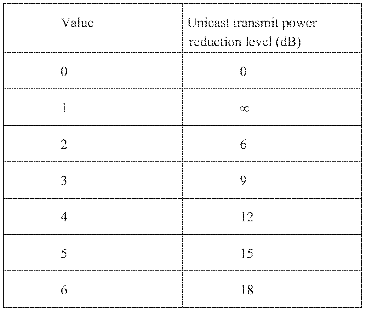
- the respective numerical element has a value selected from the group consisting of 0, 1, 2, 3, 4, 5, and 6, which represent the minimum transmit power reduction levels of the first cell at 0 dB, ⁇ dB, 6 dB, 9 dB, 12 dB, 15 dB, and 18 dB, respectively, from a nominal transmit power level.
- the minimum transmit power reduction level of 0 dB means that the first cell transmits signals at its nominal power and the second cell may not schedule any user equipment in a corresponding downlink subframe due to high interference.
- the minimum transmit power reduction level of oo dB means that the first cell will not schedule any user equipment in a corresponding downlink subirame.
- the minimum transmit power reduction level of 6 dB, 9 dB, 12 dB, 15 dB, and 18 dB means that the first cell schedules any user equipment in a corresponding downlink subframe below a
- the first cell is an aggressor cell and the second cell is a victim cell .
- the first cell is configured to transmit the data structure to the second cell in a message through an X2 interface between the two ceils defined by the 3GPP standard.
- the first cell is a macro eNB and the second cell is one selected from the group consisting of a remote radio head, a pico eNB, and a femto eNB.
- a method of conveying transmit power information from a first cell to a second cell comprises: preparing a first data structure at the first cell, the first data structure including a plurality of elements and each element corresponding to a respective downlink subframe in a radio frame associated with the first cell. Each element's value indicates whether the second cell can schedule any user equipment during a corresponding downlink subframe.
- the first cell also prepares a second data stnicture, the second data structure including a plurality of elements and each element corresponding to a respective downlink subframe during which the second cell can schedule user equipments.
- Each element's value indicates a respective minimum transmit power reduction level promised by the first cell during the corresponding downlink subframe.
- Both the first data structure and the second data structure are transmitted from the first cell to the second cell via a predefined interface.
- the second cell is configured to schedule one or more user equipments in one or more downlink subirames of the radio frame in accordance with the first data structure and the second data structure.
- the first data structure is an almost blank subframe (ABS) pattern bitmap, a binary value of 0 in the bitmap indicating that the second cell may not schedule any user equipment during a corresponding downlink subframe and a binary value of 1 indicating that the second cell may schedule user equipment in accordance with the second data structure.
- the value of an element in the second data structure is one selected from the group consisting of 0, 1 , 2, 3, 4, and 5, which correspond to the first cell's minimum transmit power reduction levels of ⁇ IB, 6 dB, 9 dB, 12 dB, 15 dB, and 18 dB, respectively, from a nominal transmit power level.
- the first cell is an aggressor cell and the second cell is a victim cell.
- the first cell is configured to transmit the first and second data structures to the second cell in a message through an X2 interface between the two cells defined by the 3G PP standard.
- the first cell is a macro eNB and the second cell is one selected from the group consisting of a remote radio head, a pico eNB, and a femto eNB.
- a method of conveying transmit power information from a first cell to a second cell comprises: preparing a first data structure at the firs t cell, the firs t data structure including a plurality of elements and each element corresponding to a respective downlink subframe in a radio frame associated with the first cell. Each element's value indicates whether the first cell promises a transmit power reduction during the corresponding downlink subframe.
- the first ceil also prepares a second data structure.
- the second data structure includes a plurality of elements, each element corresponding to a respective downlink subframe during which the first cell promises a transmit power reduction and its value indicating a respective threshold under which the first cell agrees to keep its maximum transmit power during the downlink subframe.
- the first data structure and the second data structure are transmitted from the first cell to the second cell via a predefined interface.
- the second cell is configured to schedule one or more user equipments in one or more downlink subframes of the radio frame in accordance with the first data structure and the second data structure.
- the first data structure is an almost blank subframe (ABS) pattern bitmap, a binary value of 0 in the bitmap indicating that the first cell does not promise any transmit power reduction during a corresponding downlink subframe and a binary value of 1 indicating that the first cell promises a predefined transmit power reduction in accordance with the second data structure.
- the threshold of an element in the second data structure is one selected from the group consisting of 6 dB, 7 dB, 8 dB, 9 dB, 10 dB, 1 1 dB, 12 dB, 13 dB, 14 dB, 15 dB, 16 dB, 17 dB, and 18 dB, and oo dB, respectively.
- the first cell is an aggressor ceil and the second cell is a victim ceil.
- the first cell is configured to transmit the first and second data structures to the second cell in one message through an X2 interface between the two cells defined by the 3G PP standard.
- the first cell is a macro eNB and the second cell is one selected from the group consisting of a remote radio head, a pico eNB, and a femto eNB.
- a method of exchanging resource status information between a first cell and a second cell comprises: the first cell transmitting a request to the second cell via a predefined interface; and in response to the request, the second cell transmitting a data structure to the first cell via a predefined interface.
- the first cell is an aggressor ceil and the second cell is a victim cell.
- the second cell is configured to transmit the data structure to the first cell in a message through an X2 interface between the two cells defined by the 3GPP standard.
- the data structure includes a percentage of the used reduced power ABS resource, the numerator of the percentage representing the number of resource blocks allocated (i.e., actually used) by the victim cell within the usable reduced power ABS and the denominator of the percentage representing the total number of resource blocks within the usable reduced power ABS in the victim cell.
- the first cell is a macro eNB and the second cell is one selected from the group consisting of a remote radio head, a pico eNB, and a femto eNB.
- FIGS. 1A and IB depict, respectively, the network architecture of LTE
- FIGS. 2A and 2B depict, respectively, the structure of a radio frame in the time domain and an almost blank subframe (ABS) pattern info bitmap.
- ABS almost blank subframe
- FIGS. 3A and 3B depict, respectively, a first exemplary implementation of conveying transmit power information from a first cell to a second cell and an associated data structure in accordance with some implementations.
- FIGS. 4A through 4C depict, respectively, a second exemplary
- FIGS. 5A through 5C depict, respectively, a third exemplary implementation of con veying transmit power information from a first cell to a second ceil and two associated data structures in accordance with some implementations.
- FIG. 6 depicts an exemplary implementation of conveying used ABS pattern information from a second ceil to a first cell in response to a request from the first cell.
- FIG. 7 depicts an exemplary implementation of conveying used reduced power ABS status information from a second cell to a first cell in response to a request from the first cell.
- FIGS. 1A and IB depict, respectively, the network architecture of LTE
- FIG. 1 A depicts that E-UTRAN 10, which stands for "Evolved UMTS Terrestrial Radio Access Network", is the air interface of 3GPP's Long Term Evolution Advanced (LTE-A).
- the E-UTRAN 10 consists of a plurality of eNBs (11, 12, 13) on the network side, each eN B having a specific coverage area and responsible for scheduling one or more User Equipments (UEs) in the coverage area,
- the eNBs are connected to each other via the X2 interface, and they connect to the Evolved Packet Core 20 (EPC) network via the S I interface.
- EPC Evolved Packet Core 20
- a typical high power node which has a maximum allowable transmit power of 46 dBm for a 10 MHz carrier bandwidth, can create a relatively large coverage area.
- low power nodes which have a smaller coverage area than the high power node but may improve the quality and reliability of the coverage pro vided by the high power node, have been introduced into the large coverage area.
- These low power nodes include remote radio heads, pico eNBs, home eNBs (HeNBs), and the like.
- the maximum allowable transmit power of a remote radio head/pico eNB or a HeNB is typically 30 dBm or 20 dBm for a 10 MHz carrier bandwidth.
- terms like "high power cell,” “high power node,” “macro cell,” and “micro eNB” are used interchangeably .
- the coverage area of a low power node is referred to as a pico eNB (or cell), a femto eNB (or cell), a hotzone eNB (or cell), a low power eNB (or cell), or the like, any f which might be used interchangeably herein.
- a pico cell is a small cellular base station with a dedicated backhaul connection to the sendee provider's core network (e.g., through SI interface in 3GPP) and other pico/macro cells (e.g., through X2 interface in 3GPP).
- a femto cell is also a small cellular base station designed for use at a home or small business. The femto cell connects to the service provider's network via the broadband (such as DSL or cable).
- the HeNB may have no direct interface to other femto cells or any macro cell,
- FIG. IB depicts one pico eNB 100 and one macro eNB 140.
- the macro eNB 140 has a large coverage area 160 and the pico eNB 100 has a small coverage area 180, which is inside the coverage area 160.
- the small coverage area 180 is di vided into an inner area 190 and an edge area 170. If a UE (e.g., the center UE 120) is located within the inner area 190, the user equipment is more likely connected to the pico eNB 100 and not affected by other neighboring cells including the macro eNB 140.
- a UE e.g., the center UE 120
- a UE located in the edge area 170 may receive both useful signal 130 from the pico eNB 100 and strong interference 150 from the macro eNB 140 such that the latter may affect the quality of the useful signal received by the edge UE 110.
- a macro ceil UE e.g., the macro UE 195
- the signal from the pico eNB 100 may also cause interference to the signal the macro cell UE receives from the macro eNB 140.
- the interference may be so strong that the affected UE cannot maintain a normal service from its serving cell.
- FIG. 2 A depicts an exemplary 10- nis radio frame 200, which is divided into ten 1-ms subframes.
- the data structure for storing the A BS configuration has the same number of bits as the number of subframes in a radio frame.
- the usable ABS Pattern Info 220 is defined as a bitmap, each position in the bitmap representing a corresponding downlink subframe.
- a binary value "1” corresponds to a subframe that has been designated as being protected from inter-cell interference from the aggressor cell, and is therefore available to be used by the victim cell for downlink scheduling.
- a binary ' value "0" is used for identifying other subframes that have been reserved by the aggressor cell for its own use.
- the ABS Pattern Info 220 identifies the subframes designated as almost blank subframes by the sending eNB (typically, of the aggressor cell) for the purpose of interference coordination.
- the recei ving eNB (typically, of the victim cell) may consider such information when scheduling its own serving UEs.
- the aggressor cell also sends a request for feedback to the victim cell in order to know the victim cell's used ABS pattern and evaluate the need for modification of the ABS Pattern Info 220.
- the victim cell ' s pattern represented by the bitmap is a subset of, or the same as, the corresponding "ABS Pattern Info" message from the aggressor cell.
- the aggressor cell periodically mutes the transmission that inflicts interference onto other victim cells for each designated subirame defined in the ABS
- Pattern info message so that the victim cells have a chance to serve their own UEs otherwise suffering the interference from the aggressor cell in these subframes.
- this muting is incomplete.
- Certain signals such as the common reference symbols, the primary and secondary synchronization signals (PSS and SSS), the physical broadcast channel (PBCH), and the system information block (SIB) and paging with their associated PDCCH, have to be transmitted even in the otherwise muted subframes, e.g., to avoid radio link failure or for reasons of backwards compatibility.
- Such muted subframes are thus referred to as almost blank subframes (ABS).
- the time domain muting (TDM) patterns are configured semi-statically and exchanged between different eNBs over the X2 interface.
- the UEs in the vicinity of a victim cell are categorized into two groups:
- muting e.g., the center UE 120 and the macro UE 195 in FIG. I B).
- the macro UEs with good coverage e.g., the macro UE 195
- the ABSs with reduced power transmission w r hiie still maintaining the interference to the pico eNB 100 below a predefined level
- the aggressor cell utilizes the resources that would otherwise be wasted for the sake of avoiding interference to pico cell(s ).
- terms like "Reduced power ABS” or "low power ABS” are used interchangeably herein to refer to the subframe(s) w r hich is designated by the aggressor cell as allowing lower than nominal transmit power on unicast PDSCH and associated physical downlink control channel (PDCCH).
- PDCH physical downlink control channel
- the ABS pattern information in FIG. 2B makes it difficult for the victim cell to distinguish the A13S supporting reduced power unicast PDSCH/PDCCH from the A13S without any unicast traffic.
- This limitation affects the performance of edge UE in the victim cell because a particular edge UE within the victim cell may still observe strong interference from the aggressor cell in the reduced power ABS.
- the victim cell i.e., the receiver of the ABS pattern information
- the victim cell eNB may schedule a particular edge UE in the reduced power ABS while believing that the ABS is a normal ABS.
- FIGS. 3A and 3B depict, respectively, a first implementation of conveying transmit power information from a first cell to a second cell and an associated data stmcture.
- the information of the reduced power ABS is conveyed by modifying the ABS Pattern info 220 shown in FIG. 2B.
- a numerical string is used to represent the ABS and the reduced power ABS allocation from the aggressor cell to the victim cell.
- Each position in the string of the "reduced power ABS pattern info" 300 represents a downlink subframe, for which the value " 1" indicates "ABS"; the value "0" indicates "non-ABS" and the value "2" indica tes "reduced power ABS".
- the ABS pattern is
- one reduced power ABS subframe could be reduced by at least 6 dB from the nominal transmit power while another reduced power ABS subframe could be reduced by at least 12 dB from the nominal transmit power.
- minimum transmit power reduction level stands for the minimum amount of transmit power reduction that an aggressor cell has promised or agreed relative to its nominal transmit power.
- a victim cell can leverage such information to determine if it can schedule a UE within a particular downlink subframe for a given minimum transmit power reduction level promised by the aggressor cell. This scheme gives more flexibility to both the aggressor cell and the victim cell in terms of scheduling their respective serving UEs.
- the table 1 belo is an example of different values in the string and their corresponding transmit power reduction levels.
- FIG. 3A illustrate the message from the first cell 310 (typically the aggressor cell) to the second cell 320 (typically the victim cell) regarding the "reduced power ABS pattern info" 300.
- FIGS. 4A-4C depict, respectively, a second implementation of conveying transmit power information from a first cell to a second cell and two associated data structures.
- the information of reduced power ABS can be conveyed without modifying the conventional "A BS Pattern Info" 410.
- a new information entity (IE) defined as "relative reduced power ABS position info” 420 is used for supplementing the "ABS Pattern Info” 410.
- a binary bitmap 410 shown in FIG. 4B represents the relative positions of reduced power ABSs in all the subframes designated as ABS by the aggressor cell.
- Each position in the bitmap represents a downlink subfrarne, for which the value "1" indicates “reduced power ABS” and the value "0" indicates "ABS”.
- the length of the bit siring in the "relative reduced power ABS position info” 420 is the number of positions in the "ABS Pattern info" bit string 300 whose value is " 1".
- a numerical string is used to indicate the different transmit power reduction levels in reduced power ABS.
- the table 2 is an example of different values in the string and their corresponding transmit power reduction levels in the "relative reduced power ABS position info" 420.
- FIG. 4A illustrates the messages from the first cell 310 (typically the aggressor cell) to the second cell 320 (typically the victim cell) regarding the "relative reduced power ABS position info” 420.
- the "ABS Pattern Info" 410 and the "relative reduced power ABS position info” 420 are contained into one message or kept in separated messages when transmitted between the two cells.
- FIGS. 5A-5C depict, respectively, a third implementation of conveying transmit power information from a first cell to a second ceil and two associated data
- information of the reduced power ABSs can be conveyed by defining a new information entity "Relative Reduced Tx Power" 510 (RRTP), which is again a bitmap. Each position in the bitmap represents a downlink subframe (i.e., first
- RRTP threshold mav b e one of the values RR TP mreshoid e ⁇ 6,7,8,9,10,11,12,13,14,15,16,17,18,
- a combination of the "RRTP threshold" 520 and the “Relative Reduced Tx Power” 510 provides an indication on the power restriction of each downlink subframe in a cell and other information needed by a neighbor cell for performing the interference coordination. Note that the length of the bit string of the "Relative Reduced Tx Power (RRTP)" 510 could be the same as that of the "ABS Pattern Info" 220 in FIG. 2B.
- FIG. 5A illustrates the messages from the first cell 310 (typically the aggressor cell) to the second cell 320 (typically the victim cell) using the "Relative Reduced Tx Power" 510, Note that the "Relative Reduced Tx Power" 510 and the "RRTP threshold” 520 could be contained into one message or kept in separated messages,
- an aggressor cell may request feedback from a victim cell about the ABS pattern information that is used by the victim cell. This feedback indicates the ABS sub frames actually used in the victim cell.
- the resource status reporting is defined as in 3 GPP TS 36.423: "Evolved Universal Terrestrial Radio Access Network (E ⁇ UTRAN); X2 application protocol (X2AP)," which is incorporated by reference in its entirety.
- FIG. 6 depicts that the aggressor cell (the first ceil 310) sends an ABS usage request 610 to the victim ceil (the second cell 320) for its used ABS pattern information and the victim cell then replies to the aggressor cell by providing its used ABS pattern information 620.
- a "downlink ABS status" information entity which represents the percentage of the used ABS resources, is specified in the feedback from the victim ceil to the aggressor cell.
- the numerator of the percentage represents the number of resource blocks within the ABS indicated in the Usable ABS Pattern Info IE, which have been allocated (i.e., actually used) by the victim cell.
- the denominator of the percentage represents the total number of resource blocks within the ABS indicated in the Usable ABS Pattern Info IE.
- such scheme cannot provide information about accura te ABS resource utilizat tion by the victim ceil if both ABS and reduced power ABS are contained in the usable ABS Pattern Info IE.
- the aggressor ceil (the recei ver of the downlink ABS status) cannot tell whether the ABS status feedback is for a normal ABS without no unicast traffic or a reduced power ABS.
- the aggressor cell eNB cannot adjust the normal ABS and the reduced power ABS patterns accurately.
- a "reduced power (RP) ABS status" IE is also proposed, which represents the percentage of used resources in the reduced power ABS.
- FIG. 7 depicts that the aggressor cell (first cell 310) sends an RP ABS status request 710 to the victim cell (second cell 320) for the used reduced power ABS status information and the victim cell then replies to the aggressor cell by providing an RP ABS status 720.
- the numerator of the percentage represents the number of resource blocks allocated by the victim cell within the usable reduced power ABS and the denominator of the percentage is the total number of resource blocks within the usable reduced power ABS in the victim cell.
- first, second, etc. may he used herein to describe various elements, these elements should not be limited by these terms. These terms are only used to distinguish one element from another.
- first ranking criteria could be termed second ranking criteria, and, similarly, second ranking criteria could be termed first ranking criteria, without departing from the scope of the present invention.
- First ranking criteria and second ranking criteria are both ranking criteria, but they are not the same ranking criteria.
- the phrase “if it is determined [that a stated condition precedent is true]” or “if [a stated condition precedent is true]” or “when [a stated condition precedent is true]” may be construed to mean “upon determining” or “in response to determining” or “in accordance with a determination” or “upon detecting” or “in response to detecting” that the stated condition precedent is true, depending on the context.
- stages that are not order dependent may be reordered and other stages may be combined or broken out. While some reordering or other groupings are specifically mentioned, others will be obvious to those of ordinary skill in the art and so do not present an exhaustive list of alternatives. Moreover, it should be recognized that the stages could be implemented in hardware, firmware, software or any combination thereof. [0050]
- the foregoing description, for purpose of explanation, has been described with reference to specific implementations. However, the illustrative discussions above are not intended to be exhaustive or to limit the invention to the precise forms disclosed. Many modifications and variations are possible in view of the above teachings. The
Landscapes
- Engineering & Computer Science (AREA)
- Computer Networks & Wireless Communication (AREA)
- Signal Processing (AREA)
- Mobile Radio Communication Systems (AREA)
Description
TECHNICAL FI ELD
[0001] The present invention generally relates to interference management in a heterogeneous network (HetNet) system, and in particular, to systems and methods of conveying transmit power information associated with different subframes between an aggressor cell and a victim cell.
BACKGROUND
[0002] Heterogeneous networks are one of many features in LTE Ad vanced (LTE-A).
The idea is that a network should not only consist of a single type of eNodeB (eNB) like the case of a homogeneous network, but also deploy eNBs of different capabilities, e.g., of different transmit-power classes. These eNBs are referred to as macro eNBs (MeNB), pico eNBs (PeNB) and femto/home eNBs (HeNB), which are meant for basic outdoor, outdoor hotspot, and indoor/enterprise coverage, respectively. In other words, the HetNet deployment consists of deploying both high-power and low-power nodes with the low-power nodes placed throughout the layout of high-power nodes, Although HetNet offers opportunities to enable large-scale, low-cost deployment of small base stations below rooftops to improve user experience at hotspots or to improve the network coverage, it introduces new challenges to inter-cell interference coordination within the same channel as well as load balancing and user mobility in idle and active mode.
SUMMARY
[0003] In accordance with some implementations, a method of conveying transmit power information from a first cell to a second cell includes: preparing a data structure at the first cell, the data structure including a plurality of elements and each element corresponding to a respective downlink subframe in a radio frame associated with the first cell. Each element's value corresponds to a respective minimum transmit power reduction level promised by the first cell during the downlink subframe. The data structure is transmitted from the first cell to the second cell via a predefined interface. The second cell is configured to schedule one or more user equipments in one or more downlink subframes of the radio frame in accordance with the data structure.
[0004] According to some implementations, the data structure is a string including a plurality of numerical elements, a relative position of a respective numerical element in the string corresponding to a relative position of a respective downlink subirame in the radio frame. The respective numerical element has a value selected from the group consisting of 0, 1, 2, 3, 4, 5, and 6, which represent the minimum transmit power reduction levels of the first cell at 0 dB,∞ dB, 6 dB, 9 dB, 12 dB, 15 dB, and 18 dB, respectively, from a nominal transmit power level.
[0005] According to some implementations, the minimum transmit power reduction level of 0 dB means that the first cell transmits signals at its nominal power and the second cell may not schedule any user equipment in a corresponding downlink subframe due to high interference. The minimum transmit power reduction level of oo dB means that the first cell will not schedule any user equipment in a corresponding downlink subirame. The minimum transmit power reduction level of 6 dB, 9 dB, 12 dB, 15 dB, and 18 dB means that the first cell schedules any user equipment in a corresponding downlink subframe below a
corresponding transmit power level, which is reduced by an amount defined by the minimum transmit power reduction level from a nominal transmit power level .
[0006] According to some implementations, the first cell is an aggressor cell and the second cell is a victim cell . The first cell is configured to transmit the data structure to the second cell in a message through an X2 interface between the two ceils defined by the 3GPP standard. For example, the first cell is a macro eNB and the second cell is one selected from the group consisting of a remote radio head, a pico eNB, and a femto eNB.
[0007] In accordance with some implementations, a method of conveying transmit power information from a first cell to a second cell comprises: preparing a first data structure at the first cell, the first data structure including a plurality of elements and each element corresponding to a respective downlink subframe in a radio frame associated with the first cell. Each element's value indicates whether the second cell can schedule any user equipment during a corresponding downlink subframe. The first cell also prepares a second data stnicture, the second data structure including a plurality of elements and each element corresponding to a respective downlink subframe during which the second cell can schedule user equipments. Each element's value indicates a respective minimum transmit power reduction level promised by the first cell during the corresponding downlink subframe. Both the first data structure and the second data structure are transmitted from the first cell to the second cell via a predefined interface. The second cell is configured to schedule one or more
user equipments in one or more downlink subirames of the radio frame in accordance with the first data structure and the second data structure.
[0008] According to some implementations, the first data structure is an almost blank subframe (ABS) pattern bitmap, a binary value of 0 in the bitmap indicating that the second cell may not schedule any user equipment during a corresponding downlink subframe and a binary value of 1 indicating that the second cell may schedule user equipment in accordance with the second data structure. The value of an element in the second data structure is one selected from the group consisting of 0, 1 , 2, 3, 4, and 5, which correspond to the first cell's minimum transmit power reduction levels of∞ IB, 6 dB, 9 dB, 12 dB, 15 dB, and 18 dB, respectively, from a nominal transmit power level.
[0009] According to some implementations, the first cell is an aggressor cell and the second cell is a victim cell. The first cell is configured to transmit the first and second data structures to the second cell in a message through an X2 interface between the two cells defined by the 3G PP standard. The first cell is a macro eNB and the second cell is one selected from the group consisting of a remote radio head, a pico eNB, and a femto eNB.
[0010] In accordance with some implementations, a method of conveying transmit power information from a first cell to a second cell comprises: preparing a first data structure at the firs t cell, the firs t data structure including a plurality of elements and each element corresponding to a respective downlink subframe in a radio frame associated with the first cell. Each element's value indicates whether the first cell promises a transmit power reduction during the corresponding downlink subframe. The first ceil also prepares a second data structure. The second data structure includes a plurality of elements, each element corresponding to a respective downlink subframe during which the first cell promises a transmit power reduction and its value indicating a respective threshold under which the first cell agrees to keep its maximum transmit power during the downlink subframe. The first data structure and the second data structure are transmitted from the first cell to the second cell via a predefined interface. The second cell is configured to schedule one or more user equipments in one or more downlink subframes of the radio frame in accordance with the first data structure and the second data structure.
[0011] According to some implementations, the first data structure is an almost blank subframe (ABS) pattern bitmap, a binary value of 0 in the bitmap indicating that the first cell does not promise any transmit power reduction during a corresponding downlink subframe
and a binary value of 1 indicating that the first cell promises a predefined transmit power reduction in accordance with the second data structure. The threshold of an element in the second data structure is one selected from the group consisting of 6 dB, 7 dB, 8 dB, 9 dB, 10 dB, 1 1 dB, 12 dB, 13 dB, 14 dB, 15 dB, 16 dB, 17 dB, and 18 dB, and oo dB, respectively.
[0012] According to some implementations, the first cell is an aggressor ceil and the second cell is a victim ceil. The first cell is configured to transmit the first and second data structures to the second cell in one message through an X2 interface between the two cells defined by the 3G PP standard. The first cell is a macro eNB and the second cell is one selected from the group consisting of a remote radio head, a pico eNB, and a femto eNB.
[0013] According to some impl ementations, a method of exchanging resource status information between a first cell and a second cell comprises: the first cell transmitting a request to the second cell via a predefined interface; and in response to the request, the second cell transmitting a data structure to the first cell via a predefined interface.
[0014] According to some implementations, the first cell is an aggressor ceil and the second cell is a victim cell. The second cell is configured to transmit the data structure to the first cell in a message through an X2 interface between the two cells defined by the 3GPP standard. The data structure includes a percentage of the used reduced power ABS resource, the numerator of the percentage representing the number of resource blocks allocated (i.e., actually used) by the victim cell within the usable reduced power ABS and the denominator of the percentage representing the total number of resource blocks within the usable reduced power ABS in the victim cell. The first cell is a macro eNB and the second cell is one selected from the group consisting of a remote radio head, a pico eNB, and a femto eNB.
BRIEF DESCRIPTION OF THE DRAWINGS
[0015] Different aspects of the present invention as well as features and advantages thereof will be more clearly understood hereinafter because of a detailed description of implementations of the present invention when taken in conjunction with the accompanying drawings, which are not necessarily drawn to scale. Like reference numerals refer to corresponding parts throughout the several views of the drawings.
[0016] FIGS. 1A and IB depict, respectively, the network architecture of LTE
Advanced (LTE-A) and the interference between a macro eNB and a pico eNB.
[0017] FIGS. 2A and 2B depict, respectively, the structure of a radio frame in the time domain and an almost blank subframe (ABS) pattern info bitmap.
[0018] FIGS. 3A and 3B depict, respectively, a first exemplary implementation of conveying transmit power information from a first cell to a second cell and an associated data structure in accordance with some implementations.
[0019] FIGS. 4A through 4C depict, respectively, a second exemplary
implementation of conveying transmit power information from a first ceil to a second cell and two associated data structures in accordance with some implementations.
[0020] FIGS. 5A through 5C depict, respectively, a third exemplary implementation of con veying transmit power information from a first cell to a second ceil and two associated data structures in accordance with some implementations.
[0021] FIG. 6 depicts an exemplary implementation of conveying used ABS pattern information from a second ceil to a first cell in response to a request from the first cell.
[0022] FIG. 7 depicts an exemplary implementation of conveying used reduced power ABS status information from a second cell to a first cell in response to a request from the first cell.
DESCRIPTION OF EMBODIMENTS
[0023] Reference will now be made in detail to implementations, examples of which are illustrated in the accompanying drawings. In the following detailed description, numerous non-limiting specific details are set forth in order to assist in understanding the subject matter presented herein. It will be apparent, however, to one of ordinary skill in the art that various alternati ves may be used without departing from the scope of the present invention and the subject matter may be practiced without these specific details. For example, it will be apparent to one of ordinary' skil l in the art that the subject matter presented herein can be implemented on many types of outdoor radios systems.
[0024] FIGS. 1A and IB depict, respectively, the network architecture of LTE
Advanced and the interference between a macro eNB and a pico eNB. FIG. 1 A depicts that E-UTRAN 10, which stands for "Evolved UMTS Terrestrial Radio Access Network", is the air interface of 3GPP's Long Term Evolution Advanced (LTE-A). The E-UTRAN 10 consists of a plurality of eNBs (11, 12, 13) on the network side, each eN B having a specific coverage area and responsible for scheduling one or more User Equipments (UEs) in the
coverage area, The eNBs are connected to each other via the X2 interface, and they connect to the Evolved Packet Core 20 (EPC) network via the S I interface.
[0025] A typical high power node, which has a maximum allowable transmit power of 46 dBm for a 10 MHz carrier bandwidth, can create a relatively large coverage area.
Several types of low power nodes (LPN), which have a smaller coverage area than the high power node but may improve the quality and reliability of the coverage pro vided by the high power node, have been introduced into the large coverage area. These low power nodes include remote radio heads, pico eNBs, home eNBs (HeNBs), and the like. The maximum allowable transmit power of a remote radio head/pico eNB or a HeNB is typically 30 dBm or 20 dBm for a 10 MHz carrier bandwidth. In the present application, terms like "high power cell," "high power node," "macro cell," and "micro eNB" are used interchangeably . As such, the coverage area of a low power node is referred to as a pico eNB (or cell), a femto eNB (or cell), a hotzone eNB (or cell), a low power eNB (or cell), or the like, any f which might be used interchangeably herein.
[0026] Besides the different transmit powers, these low power nodes have different connections to the core network (i.e., the EPC 20) and to their neighboring cells. For example, a pico cell is a small cellular base station with a dedicated backhaul connection to the sendee provider's core network (e.g., through SI interface in 3GPP) and other pico/macro cells (e.g., through X2 interface in 3GPP). A femto cell is also a small cellular base station designed for use at a home or small business. The femto cell connects to the service provider's network via the broadband (such as DSL or cable). The HeNB may have no direct interface to other femto cells or any macro cell,
[0027] When high power nodes and low power nodes are deployed in the same data/control channel, there may be interference problems for high power and low power cell User Equipments (UEs). For illustrative purposes, FIG. IB depicts one pico eNB 100 and one macro eNB 140. The macro eNB 140 has a large coverage area 160 and the pico eNB 100 has a small coverage area 180, which is inside the coverage area 160. The small coverage area 180 is di vided into an inner area 190 and an edge area 170. If a UE (e.g., the center UE 120) is located within the inner area 190, the user equipment is more likely connected to the pico eNB 100 and not affected by other neighboring cells including the macro eNB 140. In contrast, a UE (e.g., the edge UE 1 10) located in the edge area 170 may receive both useful signal 130 from the pico eNB 100 and strong interference 150 from the macro eNB 140 such that the latter may affect the quality of the useful signal received by the
edge UE 110. Alternatively, when a macro ceil UE (e.g., the macro UE 195) moves close to the pico eNB 100, the signal from the pico eNB 100 may also cause interference to the signal the macro cell UE receives from the macro eNB 140. In both cases, the interference may be so strong that the affected UE cannot maintain a normal service from its serving cell. Note that in the present application, terms like "aggressor cell" and "interfering cell" are used interchangeably herein and terms like "victim cell" and "interfered ceil" are also used interchangeably herein.
[0028] One method of solving this inter-cell interference problem is to use the so- called "Almost Blank Subframe" (ABS) at the interfering cell and inform the victim cell of this ABS configuration. The eNB of the victim cell then schedules its edge UEs during the subframes defined by the ABS of other interfering cell(s). FIG. 2 A depicts an exemplary 10- nis radio frame 200, which is divided into ten 1-ms subframes. As shown in FIG. 2B, the data structure for storing the A BS configuration has the same number of bits as the number of subframes in a radio frame. In this example, a binary value "0" corresponds to the subframes that have an even index (SFN::::0, 2, 4, 6, 8) and a binary value "1" corresponds to the subframe that have an odd index (SFN=1, 3, 5, 7, 9). In this example, the usable ABS Pattern Info 220 is defined as a bitmap, each position in the bitmap representing a corresponding downlink subframe. In particular, a binary value "1" corresponds to a subframe that has been designated as being protected from inter-cell interference from the aggressor cell, and is therefore available to be used by the victim cell for downlink scheduling. A binary' value "0" is used for identifying other subframes that have been reserved by the aggressor cell for its own use.
|0029] In short, the ABS Pattern Info 220 identifies the subframes designated as almost blank subframes by the sending eNB (typically, of the aggressor cell) for the purpose of interference coordination. The recei ving eNB (typically, of the victim cell) may consider such information when scheduling its own serving UEs. In some implementations, the aggressor cell also sends a request for feedback to the victim cell in order to know the victim cell's used ABS pattern and evaluate the need for modification of the ABS Pattern Info 220. The victim cell's pattern represented by the bitmap is a subset of, or the same as, the corresponding "ABS Pattern Info" message from the aggressor cell.
[0030] In this example, the aggressor cell periodically mutes the transmission that inflicts interference onto other victim cells for each designated subirame defined in the ABS
Pattern info message, so that the victim cells have a chance to serve their own UEs otherwise
suffering the interference from the aggressor cell in these subframes. In some im lementations, this muting is incomplete. Certain signals such as the common reference symbols, the primary and secondary synchronization signals (PSS and SSS), the physical broadcast channel (PBCH), and the system information block (SIB) and paging with their associated PDCCH, have to be transmitted even in the otherwise muted subframes, e.g., to avoid radio link failure or for reasons of backwards compatibility. Such muted subframes are thus referred to as almost blank subframes (ABS). In some implementations, the time domain muting (TDM) patterns are configured semi-statically and exchanged between different eNBs over the X2 interface.
[0031] As shown in FIG. IB, the UEs in the vicinity of a victim cell are categorized into two groups:
(i) U Es that are exposed to severe interference from another cell using TDM muting and hence should be scheduled in subframes muted by the corresponding aggressor cell (e.g., the edge UE 110 in FIG. I B).
(ii) UEs that are indifferent to the interference from another eNB using the TDM
muting (e.g., the center UE 120 and the macro UE 195 in FIG. I B).
[0032] Traditionally, there is no uni-cast (i.e., point-to-point) data traffic from the eNB of an aggressor cell to a ser ed UE during the ABSs of the aggressor cell. However, such restriction of not allowing uni-cast traffic during the subframes defined by the A BS Pattern info from an aggressor cell has negative impacts on the overall system performance. On the other hand, there are many benefits for an aggressor cell to allow uni-cast traffic with lowrer than nominal power during the ABSs. For example, by allowing the transmission of uni-cast physical downlink shared channel (PDSCH) and the corresponding control channel with reduced power information in the ABS, the aggressor cell has more flexibility in transmitting signals to some particular UEs. For example, in the macro-pico example shown in FIG, I B, the macro UEs with good coverage (e.g., the macro UE 195) could be scheduled in the ABSs with reduced power transmission wrhiie still maintaining the interference to the pico eNB 100 below a predefined level, By doing so, the aggressor cell utilizes the resources that would otherwise be wasted for the sake of avoiding interference to pico cell(s ). In this application, terms like "Reduced power ABS" or "low power ABS" are used interchangeably herein to refer to the subframe(s) wrhich is designated by the aggressor cell as allowing lower
than nominal transmit power on unicast PDSCH and associated physical downlink control channel (PDCCH).
[0033] The ABS pattern information in FIG. 2B makes it difficult for the victim cell to distinguish the A13S supporting reduced power unicast PDSCH/PDCCH from the A13S without any unicast traffic. This limitation affects the performance of edge UE in the victim cell because a particular edge UE within the victim cell may still observe strong interference from the aggressor cell in the reduced power ABS. The victim cell (i.e., the receiver of the ABS pattern information) cannot tell whether a particular ABS is a normal ABS without unicast traffic or a reduced power ABS. In turn, the victim cell eNB may schedule a particular edge UE in the reduced power ABS while believing that the ABS is a normal ABS. To solve this problem, it is proposed in this application to exchange information on the reduced power ABS in addition to the conventional ABS pattern information between the aggressor and the victim cells such that the victim cell's eNB can schedule its serving UEs accordingly. As will be described below, such information can be conveyed between two cells in several ways,
[0034] FIGS. 3A and 3B depict, respectively, a first implementation of conveying transmit power information from a first cell to a second cell and an associated data stmcture. In this implementation, the information of the reduced power ABS is conveyed by modifying the ABS Pattern info 220 shown in FIG. 2B. Instead of using a binary bitmap to represent the ABS subframe information, a numerical string is used to represent the ABS and the reduced power ABS allocation from the aggressor cell to the victim cell. Each position in the string of the "reduced power ABS pattern info" 300 represents a downlink subframe, for which the value " 1" indicates "ABS"; the value "0" indicates "non-ABS" and the value "2" indica tes "reduced power ABS". The first position of the ABS pattern corresponds to subframe zero (SFN=0) within a radio frame where SFN = 0. The ABS pattern is
continuously repeated for all radio frames.
[0035] In some implementations, one reduced power ABS subframe could be reduced by at least 6 dB from the nominal transmit power while another reduced power ABS subframe could be reduced by at least 12 dB from the nominal transmit power. In this application, the term "minimum transmit power reduction level" stands for the minimum amount of transmit power reduction that an aggressor cell has promised or agreed relative to its nominal transmit power. A victim cell can leverage such information to determine if it can schedule a UE within a particular downlink subframe for a given minimum transmit
power reduction level promised by the aggressor cell. This scheme gives more flexibility to both the aggressor cell and the victim cell in terms of scheduling their respective serving UEs. One way to support this scheme and convey the relative transmit power reduction level is to use different values in the "reduced power ABS pattern info" 300. For example, each position in the string of "reduced power ABS pattern info" 300 represents a downlink subframe, for which value " 1 " at SFN=1 indicates "ABS"; value "0" at SFN 0 and SFX 2 indicates "non ABS", value "2" at SFN=3 indicates "ABS with power reduced by 6 dB", value "3" at SFN=9 indicates "ABS with power reduced by 9 dB" and so on.
10036] The table 1 belo is an example of different values in the string and their corresponding transmit power reduction levels. FIG. 3A illustrate the message from the first cell 310 (typically the aggressor cell) to the second cell 320 (typically the victim cell) regarding the "reduced power ABS pattern info" 300.
Table 1
[0037] FIGS. 4A-4C depict, respectively, a second implementation of conveying transmit power information from a first cell to a second cell and two associated data structures. In this example, the information of reduced power ABS can be conveyed without modifying the conventional "A BS Pattern Info" 410. Instead, a new information entity (IE) defined as "relative reduced power ABS position info" 420 is used for supplementing the "ABS Pattern Info" 410.
[0038] In some implementations, a binary bitmap 410 shown in FIG. 4B represents the relative positions of reduced power ABSs in all the subframes designated as ABS by the
aggressor cell. Each position in the bitmap represents a downlink subfrarne, for which the value "1" indicates "reduced power ABS" and the value "0" indicates "ABS". Note that the length of the bit siring in the "relative reduced power ABS position info" 420 is the number of positions in the "ABS Pattern info" bit string 300 whose value is " 1". By combining "ABS Pattern Info" 410 and the "relative reduced power ABS position info" 420, the victim cell can obtain the information of subframes types n on- ABS, ABS, reduced power ABS) from the aggressor cell eNB.
[0039] In some implementations, a numerical string is used to indicate the different transmit power reduction levels in reduced power ABS. As shown in FIG. 4C, each position in the string of the "relative reduced power ABS position info" 420 represents a downlink subfrarne, for which the value "0" at SI X 1 and Si 'N 9 indicates "ABS" and the value "1 " at SFN=3 indicates "ABS with power reduced by 6 dB", and so on. The table 2 is an example of different values in the string and their corresponding transmit power reduction levels in the "relative reduced power ABS position info" 420. FIG. 4A illustrates the messages from the first cell 310 (typically the aggressor cell) to the second cell 320 (typically the victim cell) regarding the "relative reduced power ABS position info" 420. In some implementations, the "ABS Pattern Info" 410 and the "relative reduced power ABS position info" 420 are contained into one message or kept in separated messages when transmitted between the two cells.
Table 2

[0040] FIGS. 5A-5C depict, respectively, a third implementation of conveying transmit power information from a first cell to a second ceil and two associated data
- I I -
structures. In this example, information of the reduced power ABSs can be conveyed by defining a new information entity "Relative Reduced Tx Power" 510 (RRTP), which is again a bitmap. Each position in the bitmap represents a downlink subframe (i.e., first
bit=subframe 0 and so on), for which the bit value RR 1 !*(; } of "0" at SFN=0 indicates "no promise on the transmit power reduction is given" and the bit value RRTP(«) of "1" at SFN=9 indicates "Transmit power reduced exceeding RRTP threshold". In particular,
1 - p max on-pp
threshold
Pout (n)
RRTP (n)
0 if no promise about the lower limit of— [s made

where: out n ) is the intended base station output power in the considered subframe; « is the subframe index;
RRTPthreshold mav be one of the values RR TPmreshoid e {6,7,8,9,10,11,12,13,14,15,16,17,18,
[dB]; and
]: max is the base station maximum output transmit power.
A combination of the "RRTP threshold" 520 and the "Relative Reduced Tx Power" 510 provides an indication on the power restriction of each downlink subframe in a cell and other information needed by a neighbor cell for performing the interference coordination. Note that the length of the bit string of the "Relative Reduced Tx Power (RRTP)" 510 could be the same as that of the "ABS Pattern Info" 220 in FIG. 2B. FIG. 5A illustrates the messages from the first cell 310 (typically the aggressor cell) to the second cell 320 (typically the victim cell) using the "Relative Reduced Tx Power" 510, Note that the "Relative Reduced Tx Power" 510 and the "RRTP threshold" 520 could be contained into one message or kept in separated messages,
[0042] In some implementations, an aggressor cell may request feedback from a victim cell about the ABS pattern information that is used by the victim cell. This feedback indicates the ABS sub frames actually used in the victim cell. The resource status reporting is defined as in 3 GPP TS 36.423: "Evolved Universal Terrestrial Radio Access Network (E~ UTRAN); X2 application protocol (X2AP)," which is incorporated by reference in its entirety. FIG. 6 depicts that the aggressor cell (the first ceil 310) sends an ABS usage request 610 to the victim ceil (the second cell 320) for its used ABS pattern information and the
victim cell then replies to the aggressor cell by providing its used ABS pattern information 620.
[0043] In the current 3GPP specification, a "downlink ABS status" information entity, which represents the percentage of the used ABS resources, is specified in the feedback from the victim ceil to the aggressor cell. The numerator of the percentage represents the number of resource blocks within the ABS indicated in the Usable ABS Pattern Info IE, which have been allocated (i.e., actually used) by the victim cell. The denominator of the percentage represents the total number of resource blocks within the ABS indicated in the Usable ABS Pattern Info IE. However, such scheme cannot provide information about accura te ABS resource utiliza tion by the victim ceil if both ABS and reduced power ABS are contained in the usable ABS Pattern Info IE. For example, the aggressor ceil (the recei ver of the downlink ABS status) cannot tell whether the ABS status feedback is for a normal ABS without no unicast traffic or a reduced power ABS. In turn, the aggressor cell eNB cannot adjust the normal ABS and the reduced power ABS patterns accurately. Thus, a "reduced power (RP) ABS status" IE is also proposed, which represents the percentage of used resources in the reduced power ABS.
[0044] FIG. 7 depicts that the aggressor cell (first cell 310) sends an RP ABS status request 710 to the victim cell (second cell 320) for the used reduced power ABS status information and the victim cell then replies to the aggressor cell by providing an RP ABS status 720. The numerator of the percentage represents the number of resource blocks allocated by the victim cell within the usable reduced power ABS and the denominator of the percentage is the total number of resource blocks within the usable reduced power ABS in the victim cell.
[0045] While particular implementations are described above, it will be understood it is not intended to limit the invention to these particular implementations. On the contrary, the invention includes alternatives, modifications and equivalents that are within the spirit and scope of the appended claims. Numerous specific details are set forth in order to provide a thorough understanding of the subject matter presented herein. But it will be apparent to one of ordinary skill in the art that the subject matter may be practiced without these specific details. In other instances, well-known methods, procedures, components, and circuits have not been described in detail so as not to unnecessarily obscure aspects of the
imp lementati ons .
[0046] Although the terms first, second, etc. may he used herein to describe various elements, these elements should not be limited by these terms. These terms are only used to distinguish one element from another. For example, first ranking criteria could be termed second ranking criteria, and, similarly, second ranking criteria could be termed first ranking criteria, without departing from the scope of the present invention. First ranking criteria and second ranking criteria are both ranking criteria, but they are not the same ranking criteria.
[0047] The terminology used in the description of the in vention herein is for the purpose of describing particular implementations only and is not intended to be limiting of the invention. As used in the description of the invention and the appended claims, the singular forms "a," "an," and "the" are intended to include the plural forms as well, unless the context clearly indicates otherwise. It will also be understood that the term "and/or" as used herein refers to and encompasses any and all possible combinations of one or more of the associated listed items. It will be further understood that the terms "includes," "including," "comprises," and/or "comprising," when used in this specification, specify the presence of stated features, operations, elements, and/or components, but do not preclude the presence or addition of one or more other features, operations, elements, components, and/or groups thereof.
[0048] As used herein, the term "if may be construed to mean "when" or "upon" or "in response to determining" or "in accordance with a determination" or "in response to detecting," that a stated condition precedent is true, depending on the context. Similarly, the phrase "if it is determined [that a stated condition precedent is true]" or "if [a stated condition precedent is true]" or "when [a stated condition precedent is true]" may be construed to mean "upon determining" or "in response to determining" or "in accordance with a determination" or "upon detecting" or "in response to detecting" that the stated condition precedent is true, depending on the context.
[0049] Although some of the various draw ings illustrate a number of logical stages in a particular order, stages that are not order dependent may be reordered and other stages may be combined or broken out. While some reordering or other groupings are specifically mentioned, others will be obvious to those of ordinary skill in the art and so do not present an exhaustive list of alternatives. Moreover, it should be recognized that the stages could be implemented in hardware, firmware, software or any combination thereof.
[0050] The foregoing description, for purpose of explanation, has been described with reference to specific implementations. However, the illustrative discussions above are not intended to be exhaustive or to limit the invention to the precise forms disclosed. Many modifications and variations are possible in view of the above teachings. The
implementations were chosen and described in order to best explain principles of the invention and its practical applications, to thereby enable others skilled in the art to best utilize the invention and various implementations with various modifications as are suited to the particular use contemplated. Implementations include alternatives, modifications and equivalents that are within the spirit and scope of the appended claims, Numerous specific details are set forth in order to provide a thorough understanding of the subject matter presented herein. But it will be apparent to one of ordinary skill in the art that the subject matter may be practiced without these specific details. In other instances, well-known methods, procedures, components, and circuits have not been described in detail so as not to unnecessarily obscure aspects of the implementations.
Claims
1. A method of conveying transmit power information from a first cell to a second cell, comprising:
preparing a data structure at the first cell, wherein the data structure includes a plurality of elements, each element corresponding to a respective downlink subframe in a radio frame associated with the first cell and its value corresponding to a respective minimum transmit power reduction level promised by the first cell during the downlink subframe; and transmitting the data structure from the first cell to the second cell via a predefined interface, wherein the second cell is configured to schedule one or more user equipments in one or more downlink subframes of the radio frame in accordance with the data structure.
2. The method of claim 1, wherein the data structure is a string including a plurality of numerical elements, a relative position of a respective numerical element in the string corresponding to a relative position of the respective downlink subframe in the ra dio frame,
3. The method of claim 2, wherein the respective numerical element has a value selected from the group consisting of 0, 1 , 2, 3, 4, 5, and 6, which represents the first cell's minimum transmit power reduction levels at 0 dB,∞ dB. 6 dB, 9 dB, 12 dB, 15 dB, and 18 dB, respectively, from a nominal transmit power level.
4. The method of claim 3, wherein the minimum transmit power reduction level of 0 dB means that the first cell transmits at its nominal transmit power level and the second cell may not schedule any user equipment in a corresponding downlink subframe.
5. The method of claim 3, wherein the minimum transmit power reduction level of∞ dB means that the first cell will not schedule any user equipment in a corresponding downlink subframe.
6. The method of claim 3, wherein the minimum transmit power reduction level of one selected from the group consisting of 6 dB, 9 dB, 12 dB, 15 dB, and 18 dB means that the first cell will schedule any user equipment in a corresponding downlink subframe below a corresponding transmit power level, which is reduced at least an amount defined by the minimum transmit power reduction level from a nominal transmit power level.
7. The method of claim 1, wherein the first cell is an aggressor cell and the second cell is a victim cell.
8. The method of claim 1, wherein the first cell is configured to transmit the data structure to the second ceil using one message.
9. The method of claim 1, wherein the first cell is a macro eNB and the second cell is one selected from the group consisting of a remote radio head, a pico eNB, and a femto eNB.
10. The method of claim 1 , wherein the predefined interface is an X2 interface defined by 3 GPP.
1 L A method of conveying transmit power information from a first cell to a second cell, comprising:
preparing a first data structure at the first ceil, wherein the first data structure includes a plurality of elements, each element corresponding to a respective downlink subframe in a radio frame associated with the first cell and its value indicating whether or not the second cell can schedule any user equipment during the downlink subframe;
preparing a second data structure at the first cell, wherein the second data structure includes a plurality of elements, each element corresponding to a respective downlink subframe during which the second cell can schedule user equipments and its value indicating a respective minimum transmit power reduction level promised by the first cell during the downlink subframe; and
transmitting the first data structure and the second data structure from the first cell to the second ceil via a predefined interface, wherein the second cell is configured to schedule one or more user equipments in one or more downlink sub frames of the radio frame in accordance with the first data structure and the second data structure.
12. The method of claim 11 , wherein the first data structure is an almost blank subframe (ABS) pattern bitmap, a binary value of 0 in the bitmap indicating that the second cell may not schedule any user equipment during a corresponding downlink subframe and a binary value of 1 indicating that the second ceil may schedule equipments in accordance with the second data structure.
13. The method of claim 12, wherein the value of an element in the second data structure is one selected from the group consisting of 0, 1, 2, 3, 4, and 5, which coiTespond to the first cell's minimum transmit power reduction levels of∞ dB, 6 dB, 9 dB, 12 dB, 15 dB, and 18 dB, respectively, from a nominal transmit power level.
14. The method of claim 11, wherein the first cell is an aggressor cell and the second ceil is a victim ceil.
15. The method of claim 11, wherein the first cell is configured to transmit the first data structure and the second data structure to the second ceil using one message.
16. The method of claim 11, wherein the first cell is a macro eNB and the second cell is one selected from the group consisting of a remote radio head, a pico eNB, and a femto eNB.
17. The method of claim 1 1 , wherein the predefined interface is X2 interface defined by 3 GPP.
18. A method of conveying transmit power information from a first cell to a second cell, comprising:
preparing a first data structure at the first ceil, wherein the first data structure includes a plurality of elements, each element corresponding to a respective downlink subframe in a radio frame associated with the first ceil and its value indicating whether or not the first cell promises a transmit power reduction during the downlink subframe;
preparing a second data structure at the first cell, wherein the second data structure includes a plurality of elements, each element corresponding to a respective downlink subframe during which the first cell promises a transmit power reduction and its value indicating a respective threshold under which the first cell agrees to keep its maximum transmit power level during the downlink subframe; and
transmitting the first data structure and the second data structure from the first cell to the second ceil via a predefined interface, wherein the second cell is configured to schedule one or more user equipments in one or more downlink sub frames of the radio frame in accordance with the first data structure and the second data structure.
19. The method of claim 18, wherein the first data structure is an almost blank subframe (ABS) pattern bitmap, a binary value of 0 in the bitmap indicating that the first ceil does not promise any transmit power reduction during a corresponding downlink subframe and a binary value of 1 indicating that the first cell promises a predefined transmit power reduction in accordance with the second data structure.
20. The method of claim 19, wherein the threshold of an element in the second data structure is one selected from the group consisting of 6 dB, 7 dB, 8 dB, 9 dB, 10 dB, 11 dB. 12 dB, 13 dB, 14 dB, 15 dB, 16 dB, 17 dB, and 18 dB, and∞ dB, respectively.
21. The method of claim 18, wherein the first cell is an aggressor cell and the second ceil is a victim cell.
22. The method of claim 18, wherein the first cell is configured to transmit the first data structure and the second data structure to the second ceil using one message.
23. The method of claim 18, wherein the first cell is a macro eNB and the second cell is one selected from the group consisting of a remote radio head, a pico eNB, a femto eNB.
24. The method of claim 18, wherein the predefined interface is X2 interface defined by 3 GPP.
25. A method of exchanging resource status information between a first cell and a second cell, comprising:
the first cell transmitting a request to the second cell via a predefined interface; and in response to the request, the second cell transmitting a data structure to the first cell via a predefined interface.
26. The method of claim 25, wherein the data structure includes a percentage of used resources in the second cell within one or more downlink subfranies corresponding to transmit power reduction promised by the first cell during the one or more downlink subframes.
27. The method of claim 26, wherein a numerator of the percentage consists of resource blocks allocated by the second cell within the one or more downlink subframes
corresponding to transmit power reduction promised by the first ceil during the one or more downlink subframes.
28. The method of claim 26, wherein a denominator of the percentage is a total number of resource blocks in the second cell within the one or more downlink subframes corresponding to transmit power reduction promised by the first ceil during the one or more downlink subframes.
29. The method of claim 25, wherein the first cell is an aggressor cell and the second cell is a victim ceil,
30. The method of claim 25, wherein the second cell is configured to transmit the data structure to the first cell using one message.
31. The method of claim 25, wherein the first cell is a macro eNB and the second cell is one selected from the group consisting of a remote radio head, a pico eNB, and a femto eNB.
32. The method of claim 25, wherein the predefined interface is X2 interface defined by 3 GPP.
Priority Applications (3)
| Application Number | Priority Date | Filing Date | Title |
|---|---|---|---|
| CN201380014398.8A CN104170278B (en) | 2012-03-13 | 2013-02-27 | Interference management method in heterogeneous network |
| US14/379,254 US9736788B2 (en) | 2012-03-13 | 2013-02-27 | Interference management in the heterogeneous network |
| EP13761672.8A EP2826169B1 (en) | 2012-03-13 | 2013-02-27 | Interference management in the heterogeneous network |
Applications Claiming Priority (4)
| Application Number | Priority Date | Filing Date | Title |
|---|---|---|---|
| US201261610385P | 2012-03-13 | 2012-03-13 | |
| US61/610,385 | 2012-03-13 | ||
| US201261668912P | 2012-07-06 | 2012-07-06 | |
| US61/668,912 | 2012-07-06 |
Publications (1)
| Publication Number | Publication Date |
|---|---|
| WO2013138068A1 true WO2013138068A1 (en) | 2013-09-19 |
Family
ID=49161658
Family Applications (1)
| Application Number | Title | Priority Date | Filing Date |
|---|---|---|---|
| PCT/US2013/028051 Ceased WO2013138068A1 (en) | 2012-03-13 | 2013-02-27 | Interference management in the heterogeneous network |
Country Status (4)
| Country | Link |
|---|---|
| US (1) | US9736788B2 (en) |
| EP (1) | EP2826169B1 (en) |
| CN (1) | CN104170278B (en) |
| WO (1) | WO2013138068A1 (en) |
Cited By (1)
| Publication number | Priority date | Publication date | Assignee | Title |
|---|---|---|---|---|
| US20160088571A1 (en) * | 2014-09-24 | 2016-03-24 | Samsung Electronics Co., Ltd. | Method and apparatus for controlling transmission power in transmitter of wireless communication system |
Families Citing this family (10)
| Publication number | Priority date | Publication date | Assignee | Title |
|---|---|---|---|---|
| US10164693B2 (en) | 2013-05-09 | 2018-12-25 | Intel IP Corporation | Reduction of buffer overflow |
| US20160295597A1 (en) * | 2013-07-26 | 2016-10-06 | Intel IP Corporation | Signaling interference information for user equipment assistance |
| WO2015072902A1 (en) * | 2013-11-12 | 2015-05-21 | Telefonaktiebolaget L M Ericsson (Publ) | Reducing interference between network nodes |
| KR101781015B1 (en) * | 2013-12-02 | 2017-09-25 | 후아웨이 테크놀러지 컴퍼니 리미티드 | Method and system for muting radio resources in a wireless communication system |
| WO2015089840A1 (en) * | 2013-12-20 | 2015-06-25 | 华为技术有限公司 | Method, centralized controller, and device for radio resource optimization management |
| US9692581B1 (en) * | 2015-02-02 | 2017-06-27 | Sprint Spectrum L.P. | Systems and methods for load and interference coordination in a wireless communication network |
| US10615276B2 (en) | 2017-12-22 | 2020-04-07 | International Business Machines Corporation | Integration of input/output device in vertical field-effect transistor technology |
| WO2019137406A1 (en) * | 2018-01-12 | 2019-07-18 | 华为技术有限公司 | Transmission method and network device |
| US11304151B2 (en) * | 2019-05-01 | 2022-04-12 | Jio Platforms Limited | System and method for mitigation of interference |
| CN112533275B (en) * | 2020-11-13 | 2022-01-25 | 北京科技大学 | Power control and interference pricing method and device for renewable energy heterogeneous network |
Citations (1)
| Publication number | Priority date | Publication date | Assignee | Title |
|---|---|---|---|---|
| KR20120017005A (en) * | 2010-08-17 | 2012-02-27 | 한국전자통신연구원 | Uplink transmission power control method of mobile communication system |
Family Cites Families (10)
| Publication number | Priority date | Publication date | Assignee | Title |
|---|---|---|---|---|
| US8730861B2 (en) | 2010-06-21 | 2014-05-20 | Qualcomm Incorporated | Rate matching for data and control channels in wireless communication systems |
| CN102340344B (en) | 2010-07-27 | 2015-03-25 | 电信科学技术研究院 | Method for avoiding interference between base stations in heterogeneous network, and equipment |
| KR20120080493A (en) * | 2011-01-07 | 2012-07-17 | 주식회사 팬택 | Method and apparatus for transmitting and receiving measurement pattern in comp system |
| WO2012096604A1 (en) * | 2011-01-11 | 2012-07-19 | Telefonaktiebolaget L M Ericsson (Publ) | Methods for uplink interference mitigation in non-allowed csg |
| CN102065490B (en) | 2011-01-17 | 2014-04-02 | 大唐移动通信设备有限公司 | Method and equipment for coordinating downlink transmitting power between base stations |
| EP2708075B1 (en) * | 2011-05-09 | 2019-11-13 | Telefonaktiebolaget LM Ericsson (publ) | Methods and arrangements for transmitting and receiving sub - frame specific power offset information |
| US20140198744A1 (en) * | 2011-05-17 | 2014-07-17 | Interdigital Patent Holdings, Inc. | Method and apparatus for data-splitting transmission from multiple sites |
| WO2013068041A1 (en) * | 2011-11-10 | 2013-05-16 | Nokia Siemens Networks Oy | Configuring a communication channel within a cell of a cellular network comprising another cell which uses muting patterns |
| US9332505B2 (en) * | 2011-11-11 | 2016-05-03 | Telefonaktiebolaget L M Ericsson (Publ) | Methods and apparatus for performing measurements in adaptive downlink power transmission |
| EP2781127A1 (en) * | 2011-11-14 | 2014-09-24 | Telefonaktiebolaget L M Ericsson (publ) | Methods and arrangements in a wireless communication system |
-
2013
- 2013-02-27 WO PCT/US2013/028051 patent/WO2013138068A1/en not_active Ceased
- 2013-02-27 EP EP13761672.8A patent/EP2826169B1/en active Active
- 2013-02-27 US US14/379,254 patent/US9736788B2/en active Active
- 2013-02-27 CN CN201380014398.8A patent/CN104170278B/en active Active
Patent Citations (1)
| Publication number | Priority date | Publication date | Assignee | Title |
|---|---|---|---|---|
| KR20120017005A (en) * | 2010-08-17 | 2012-02-27 | 한국전자통신연구원 | Uplink transmission power control method of mobile communication system |
Non-Patent Citations (7)
| Title |
|---|
| "3GPP; TSGRAN; Evolved Universal Terrestrial Radio Access Network (E-UTRAN); X2 application protocol (X2AP) (Release 10", 3GPP TS 36.423 V10.1.0, March 2011 (2011-03-01) |
| "3GPP; TSGRAN; Evolved Universal Terrestrial Radio Access Network(E-UTRAN); X2 application protocol(X2AP) (Release 10)", 3GPP TS 36.423 V10.1.0, March 2011 (2011-03-01), XP055162231 * |
| "On Signalling for reduced power ABS", 3GPP TSG RAN WG1 1 MEETING #68 RL-120285, 6 February 2012 (2012-02-06) |
| NEC GROUP: "Macro cell transmission power adjustment in ABS subframes for FeICIC in non-CA Scenario", 3GPP TSG-RAN WG1 #67 R1-113870, 14 November 2011 (2011-11-14), SAN FRANCISCO, USA, XP050562259 * |
| PANASONIC: "Performance Study on ABS with Reduced Macro Power", 3GPP TSG-RAN WG1 MEETING #67 R1-113806, 14 November 2011 (2011-11-14), SAN FRANCISCO, USA, XP050562255 * |
| See also references of EP2826169A4 * |
| ZTE: "On Signalling for reduced power ABS", 3GPP TSG RAN WG1 MEETING #68 R1-120285, 6 February 2012 (2012-02-06), DRESDEN, GERMANY, XP050562823 * |
Cited By (2)
| Publication number | Priority date | Publication date | Assignee | Title |
|---|---|---|---|---|
| US20160088571A1 (en) * | 2014-09-24 | 2016-03-24 | Samsung Electronics Co., Ltd. | Method and apparatus for controlling transmission power in transmitter of wireless communication system |
| US10541797B2 (en) * | 2014-09-24 | 2020-01-21 | Samsung Electronics Co., Ltd. | Method and apparatus for controlling transmission power in transmitter of wireless communication system |
Also Published As
| Publication number | Publication date |
|---|---|
| EP2826169A1 (en) | 2015-01-21 |
| EP2826169A4 (en) | 2015-10-28 |
| US20160021621A1 (en) | 2016-01-21 |
| CN104170278A (en) | 2014-11-26 |
| US9736788B2 (en) | 2017-08-15 |
| EP2826169B1 (en) | 2016-12-28 |
| CN104170278B (en) | 2017-07-28 |
Similar Documents
| Publication | Publication Date | Title |
|---|---|---|
| EP2826169B1 (en) | Interference management in the heterogeneous network | |
| JP6910409B2 (en) | Mobile communication system and base station equipment | |
| US10674407B2 (en) | Adaptive resource negotiation between base stations for enhanced interference coordination | |
| JP5674958B2 (en) | Method and apparatus for conveying measurement signaling | |
| EP2709406B1 (en) | Method and apparatus for cell selection in a wireless communication system | |
| JP2025160469A (en) | Mobile communication system and base station | |
| EP2696645B1 (en) | Method and device for inter-cell interference coordination | |
| KR101411345B1 (en) | Method and device for inter-cell interference coordination | |
| US8423072B2 (en) | Methods and devices for reducing interference in an uplink | |
| CN103202053B (en) | Configuring non-scheduled periods in heterogeneous networks for interference reduction | |
| EP2988551B1 (en) | Signal transmission method and device | |
| US20140016598A1 (en) | Device and method for transmitting control information for inter-heterogeneous cell interference adjustment in a wireless communication system | |
| US10477570B2 (en) | Advance communication resource notification in wireless communication systems having overlapping service areas | |
| TW201332382A (en) | Method for instructing user terminal to alleviate interference in a base station | |
| US20120082047A1 (en) | User equipment measurement for interference management in heterogeneous networks with femto cells | |
| JP2015529041A (en) | Apparatus, method and computer program for mobile transceiver and base station transceiver | |
| JP2015534358A (en) | Centralized management for mitigation of pilot pollution in small cell networks | |
| CN103227689B (en) | The processing method and processing device of power parameter | |
| CN102118753B (en) | Spectrum reservation and carrier switching method based on micro base station-home base station system | |
| WO2013135301A1 (en) | Power control in wireless communications | |
| WO2010032848A1 (en) | Mobile communication method, mobile communication system, and radio base station | |
| CN103200691B (en) | Control information transmission method and device | |
| GB2508604A (en) | Inter-cell interference coordination in a cellular communication system |
Legal Events
| Date | Code | Title | Description |
|---|---|---|---|
| 121 | Ep: the epo has been informed by wipo that ep was designated in this application |
Ref document number: 13761672 Country of ref document: EP Kind code of ref document: A1 |
|
| WWE | Wipo information: entry into national phase |
Ref document number: 14379254 Country of ref document: US |
|
| NENP | Non-entry into the national phase |
Ref country code: DE |
|
| REEP | Request for entry into the european phase |
Ref document number: 2013761672 Country of ref document: EP |
|
| WWE | Wipo information: entry into national phase |
Ref document number: 2013761672 Country of ref document: EP |