WO2013140502A1 - 電力変換装置 - Google Patents
電力変換装置 Download PDFInfo
- Publication number
- WO2013140502A1 WO2013140502A1 PCT/JP2012/057034 JP2012057034W WO2013140502A1 WO 2013140502 A1 WO2013140502 A1 WO 2013140502A1 JP 2012057034 W JP2012057034 W JP 2012057034W WO 2013140502 A1 WO2013140502 A1 WO 2013140502A1
- Authority
- WO
- WIPO (PCT)
- Prior art keywords
- power conversion
- conversion device
- main body
- recess
- electrical component
- Prior art date
- Legal status (The legal status is an assumption and is not a legal conclusion. Google has not performed a legal analysis and makes no representation as to the accuracy of the status listed.)
- Ceased
Links
Images


Classifications
-
- H—ELECTRICITY
- H05—ELECTRIC TECHNIQUES NOT OTHERWISE PROVIDED FOR
- H05K—PRINTED CIRCUITS; CASINGS OR CONSTRUCTIONAL DETAILS OF ELECTRIC APPARATUS; MANUFACTURE OF ASSEMBLAGES OF ELECTRICAL COMPONENTS
- H05K7/00—Constructional details common to different types of electric apparatus
- H05K7/20—Modifications to facilitate cooling, ventilating, or heating
- H05K7/2089—Modifications to facilitate cooling, ventilating, or heating for power electronics, e.g. for inverters for controlling motor
- H05K7/20927—Liquid coolant without phase change
-
- B—PERFORMING OPERATIONS; TRANSPORTING
- B60—VEHICLES IN GENERAL
- B60L—PROPULSION OF ELECTRICALLY-PROPELLED VEHICLES; SUPPLYING ELECTRIC POWER FOR AUXILIARY EQUIPMENT OF ELECTRICALLY-PROPELLED VEHICLES; ELECTRODYNAMIC BRAKE SYSTEMS FOR VEHICLES IN GENERAL; MAGNETIC SUSPENSION OR LEVITATION FOR VEHICLES; MONITORING OPERATING VARIABLES OF ELECTRICALLY-PROPELLED VEHICLES; ELECTRIC SAFETY DEVICES FOR ELECTRICALLY-PROPELLED VEHICLES
- B60L15/00—Methods, circuits, or devices for controlling the traction-motor speed of electrically-propelled vehicles
- B60L15/007—Physical arrangements or structures of drive train converters specially adapted for the propulsion motors of electric vehicles
-
- B—PERFORMING OPERATIONS; TRANSPORTING
- B60—VEHICLES IN GENERAL
- B60L—PROPULSION OF ELECTRICALLY-PROPELLED VEHICLES; SUPPLYING ELECTRIC POWER FOR AUXILIARY EQUIPMENT OF ELECTRICALLY-PROPELLED VEHICLES; ELECTRODYNAMIC BRAKE SYSTEMS FOR VEHICLES IN GENERAL; MAGNETIC SUSPENSION OR LEVITATION FOR VEHICLES; MONITORING OPERATING VARIABLES OF ELECTRICALLY-PROPELLED VEHICLES; ELECTRIC SAFETY DEVICES FOR ELECTRICALLY-PROPELLED VEHICLES
- B60L3/00—Electric devices on electrically-propelled vehicles for safety purposes; Monitoring operating variables, e.g. speed, deceleration or energy consumption
- B60L3/0023—Detecting, eliminating, remedying or compensating for drive train abnormalities, e.g. failures within the drive train
- B60L3/003—Detecting, eliminating, remedying or compensating for drive train abnormalities, e.g. failures within the drive train relating to inverters
-
- B—PERFORMING OPERATIONS; TRANSPORTING
- B60—VEHICLES IN GENERAL
- B60L—PROPULSION OF ELECTRICALLY-PROPELLED VEHICLES; SUPPLYING ELECTRIC POWER FOR AUXILIARY EQUIPMENT OF ELECTRICALLY-PROPELLED VEHICLES; ELECTRODYNAMIC BRAKE SYSTEMS FOR VEHICLES IN GENERAL; MAGNETIC SUSPENSION OR LEVITATION FOR VEHICLES; MONITORING OPERATING VARIABLES OF ELECTRICALLY-PROPELLED VEHICLES; ELECTRIC SAFETY DEVICES FOR ELECTRICALLY-PROPELLED VEHICLES
- B60L53/00—Methods of charging batteries, specially adapted for electric vehicles; Charging stations or on-board charging equipment therefor; Exchange of energy storage elements in electric vehicles
- B60L53/20—Methods of charging batteries, specially adapted for electric vehicles; Charging stations or on-board charging equipment therefor; Exchange of energy storage elements in electric vehicles characterised by converters located in the vehicle
- B60L53/22—Constructional details or arrangements of charging converters specially adapted for charging electric vehicles
-
- H—ELECTRICITY
- H05—ELECTRIC TECHNIQUES NOT OTHERWISE PROVIDED FOR
- H05K—PRINTED CIRCUITS; CASINGS OR CONSTRUCTIONAL DETAILS OF ELECTRIC APPARATUS; MANUFACTURE OF ASSEMBLAGES OF ELECTRICAL COMPONENTS
- H05K7/00—Constructional details common to different types of electric apparatus
- H05K7/20—Modifications to facilitate cooling, ventilating, or heating
- H05K7/2089—Modifications to facilitate cooling, ventilating, or heating for power electronics, e.g. for inverters for controlling motor
- H05K7/209—Heat transfer by conduction from internal heat source to heat radiating structure
-
- B—PERFORMING OPERATIONS; TRANSPORTING
- B60—VEHICLES IN GENERAL
- B60L—PROPULSION OF ELECTRICALLY-PROPELLED VEHICLES; SUPPLYING ELECTRIC POWER FOR AUXILIARY EQUIPMENT OF ELECTRICALLY-PROPELLED VEHICLES; ELECTRODYNAMIC BRAKE SYSTEMS FOR VEHICLES IN GENERAL; MAGNETIC SUSPENSION OR LEVITATION FOR VEHICLES; MONITORING OPERATING VARIABLES OF ELECTRICALLY-PROPELLED VEHICLES; ELECTRIC SAFETY DEVICES FOR ELECTRICALLY-PROPELLED VEHICLES
- B60L2210/00—Converter types
- B60L2210/10—DC to DC converters
-
- B—PERFORMING OPERATIONS; TRANSPORTING
- B60—VEHICLES IN GENERAL
- B60L—PROPULSION OF ELECTRICALLY-PROPELLED VEHICLES; SUPPLYING ELECTRIC POWER FOR AUXILIARY EQUIPMENT OF ELECTRICALLY-PROPELLED VEHICLES; ELECTRODYNAMIC BRAKE SYSTEMS FOR VEHICLES IN GENERAL; MAGNETIC SUSPENSION OR LEVITATION FOR VEHICLES; MONITORING OPERATING VARIABLES OF ELECTRICALLY-PROPELLED VEHICLES; ELECTRIC SAFETY DEVICES FOR ELECTRICALLY-PROPELLED VEHICLES
- B60L2210/00—Converter types
- B60L2210/30—AC to DC converters
-
- B—PERFORMING OPERATIONS; TRANSPORTING
- B60—VEHICLES IN GENERAL
- B60L—PROPULSION OF ELECTRICALLY-PROPELLED VEHICLES; SUPPLYING ELECTRIC POWER FOR AUXILIARY EQUIPMENT OF ELECTRICALLY-PROPELLED VEHICLES; ELECTRODYNAMIC BRAKE SYSTEMS FOR VEHICLES IN GENERAL; MAGNETIC SUSPENSION OR LEVITATION FOR VEHICLES; MONITORING OPERATING VARIABLES OF ELECTRICALLY-PROPELLED VEHICLES; ELECTRIC SAFETY DEVICES FOR ELECTRICALLY-PROPELLED VEHICLES
- B60L2210/00—Converter types
- B60L2210/40—DC to AC converters
-
- B—PERFORMING OPERATIONS; TRANSPORTING
- B60—VEHICLES IN GENERAL
- B60L—PROPULSION OF ELECTRICALLY-PROPELLED VEHICLES; SUPPLYING ELECTRIC POWER FOR AUXILIARY EQUIPMENT OF ELECTRICALLY-PROPELLED VEHICLES; ELECTRODYNAMIC BRAKE SYSTEMS FOR VEHICLES IN GENERAL; MAGNETIC SUSPENSION OR LEVITATION FOR VEHICLES; MONITORING OPERATING VARIABLES OF ELECTRICALLY-PROPELLED VEHICLES; ELECTRIC SAFETY DEVICES FOR ELECTRICALLY-PROPELLED VEHICLES
- B60L2240/00—Control parameters of input or output; Target parameters
- B60L2240/10—Vehicle control parameters
- B60L2240/36—Temperature of vehicle components or parts
-
- B—PERFORMING OPERATIONS; TRANSPORTING
- B60—VEHICLES IN GENERAL
- B60L—PROPULSION OF ELECTRICALLY-PROPELLED VEHICLES; SUPPLYING ELECTRIC POWER FOR AUXILIARY EQUIPMENT OF ELECTRICALLY-PROPELLED VEHICLES; ELECTRODYNAMIC BRAKE SYSTEMS FOR VEHICLES IN GENERAL; MAGNETIC SUSPENSION OR LEVITATION FOR VEHICLES; MONITORING OPERATING VARIABLES OF ELECTRICALLY-PROPELLED VEHICLES; ELECTRIC SAFETY DEVICES FOR ELECTRICALLY-PROPELLED VEHICLES
- B60L2240/00—Control parameters of input or output; Target parameters
- B60L2240/40—Drive Train control parameters
- B60L2240/52—Drive Train control parameters related to converters
- B60L2240/525—Temperature of converter or components thereof
-
- H—ELECTRICITY
- H01—ELECTRIC ELEMENTS
- H01F—MAGNETS; INDUCTANCES; TRANSFORMERS; SELECTION OF MATERIALS FOR THEIR MAGNETIC PROPERTIES
- H01F27/00—Details of transformers or inductances, in general
- H01F27/02—Casings
- H01F27/025—Constructional details relating to cooling
-
- H—ELECTRICITY
- H01—ELECTRIC ELEMENTS
- H01F—MAGNETS; INDUCTANCES; TRANSFORMERS; SELECTION OF MATERIALS FOR THEIR MAGNETIC PROPERTIES
- H01F27/00—Details of transformers or inductances, in general
- H01F27/08—Cooling; Ventilating
- H01F27/10—Liquid cooling
- H01F27/105—Cooling by special liquid or by liquid of particular composition
-
- Y—GENERAL TAGGING OF NEW TECHNOLOGICAL DEVELOPMENTS; GENERAL TAGGING OF CROSS-SECTIONAL TECHNOLOGIES SPANNING OVER SEVERAL SECTIONS OF THE IPC; TECHNICAL SUBJECTS COVERED BY FORMER USPC CROSS-REFERENCE ART COLLECTIONS [XRACs] AND DIGESTS
- Y02—TECHNOLOGIES OR APPLICATIONS FOR MITIGATION OR ADAPTATION AGAINST CLIMATE CHANGE
- Y02T—CLIMATE CHANGE MITIGATION TECHNOLOGIES RELATED TO TRANSPORTATION
- Y02T10/00—Road transport of goods or passengers
- Y02T10/60—Other road transportation technologies with climate change mitigation effect
- Y02T10/64—Electric machine technologies in electromobility
-
- Y—GENERAL TAGGING OF NEW TECHNOLOGICAL DEVELOPMENTS; GENERAL TAGGING OF CROSS-SECTIONAL TECHNOLOGIES SPANNING OVER SEVERAL SECTIONS OF THE IPC; TECHNICAL SUBJECTS COVERED BY FORMER USPC CROSS-REFERENCE ART COLLECTIONS [XRACs] AND DIGESTS
- Y02—TECHNOLOGIES OR APPLICATIONS FOR MITIGATION OR ADAPTATION AGAINST CLIMATE CHANGE
- Y02T—CLIMATE CHANGE MITIGATION TECHNOLOGIES RELATED TO TRANSPORTATION
- Y02T10/00—Road transport of goods or passengers
- Y02T10/60—Other road transportation technologies with climate change mitigation effect
- Y02T10/70—Energy storage systems for electromobility, e.g. batteries
-
- Y—GENERAL TAGGING OF NEW TECHNOLOGICAL DEVELOPMENTS; GENERAL TAGGING OF CROSS-SECTIONAL TECHNOLOGIES SPANNING OVER SEVERAL SECTIONS OF THE IPC; TECHNICAL SUBJECTS COVERED BY FORMER USPC CROSS-REFERENCE ART COLLECTIONS [XRACs] AND DIGESTS
- Y02—TECHNOLOGIES OR APPLICATIONS FOR MITIGATION OR ADAPTATION AGAINST CLIMATE CHANGE
- Y02T—CLIMATE CHANGE MITIGATION TECHNOLOGIES RELATED TO TRANSPORTATION
- Y02T10/00—Road transport of goods or passengers
- Y02T10/60—Other road transportation technologies with climate change mitigation effect
- Y02T10/7072—Electromobility specific charging systems or methods for batteries, ultracapacitors, supercapacitors or double-layer capacitors
-
- Y—GENERAL TAGGING OF NEW TECHNOLOGICAL DEVELOPMENTS; GENERAL TAGGING OF CROSS-SECTIONAL TECHNOLOGIES SPANNING OVER SEVERAL SECTIONS OF THE IPC; TECHNICAL SUBJECTS COVERED BY FORMER USPC CROSS-REFERENCE ART COLLECTIONS [XRACs] AND DIGESTS
- Y02—TECHNOLOGIES OR APPLICATIONS FOR MITIGATION OR ADAPTATION AGAINST CLIMATE CHANGE
- Y02T—CLIMATE CHANGE MITIGATION TECHNOLOGIES RELATED TO TRANSPORTATION
- Y02T10/00—Road transport of goods or passengers
- Y02T10/60—Other road transportation technologies with climate change mitigation effect
- Y02T10/72—Electric energy management in electromobility
-
- Y—GENERAL TAGGING OF NEW TECHNOLOGICAL DEVELOPMENTS; GENERAL TAGGING OF CROSS-SECTIONAL TECHNOLOGIES SPANNING OVER SEVERAL SECTIONS OF THE IPC; TECHNICAL SUBJECTS COVERED BY FORMER USPC CROSS-REFERENCE ART COLLECTIONS [XRACs] AND DIGESTS
- Y02—TECHNOLOGIES OR APPLICATIONS FOR MITIGATION OR ADAPTATION AGAINST CLIMATE CHANGE
- Y02T—CLIMATE CHANGE MITIGATION TECHNOLOGIES RELATED TO TRANSPORTATION
- Y02T90/00—Enabling technologies or technologies with a potential or indirect contribution to GHG emissions mitigation
- Y02T90/10—Technologies relating to charging of electric vehicles
- Y02T90/12—Electric charging stations
-
- Y—GENERAL TAGGING OF NEW TECHNOLOGICAL DEVELOPMENTS; GENERAL TAGGING OF CROSS-SECTIONAL TECHNOLOGIES SPANNING OVER SEVERAL SECTIONS OF THE IPC; TECHNICAL SUBJECTS COVERED BY FORMER USPC CROSS-REFERENCE ART COLLECTIONS [XRACs] AND DIGESTS
- Y02—TECHNOLOGIES OR APPLICATIONS FOR MITIGATION OR ADAPTATION AGAINST CLIMATE CHANGE
- Y02T—CLIMATE CHANGE MITIGATION TECHNOLOGIES RELATED TO TRANSPORTATION
- Y02T90/00—Enabling technologies or technologies with a potential or indirect contribution to GHG emissions mitigation
- Y02T90/10—Technologies relating to charging of electric vehicles
- Y02T90/14—Plug-in electric vehicles
Definitions
- the present invention is mounted on, for example, a plug-in hybrid vehicle, an electric vehicle, etc., and converts a AC input power source into a direct current to charge a high voltage battery, or converts a high voltage battery voltage into a 12V system voltage.
- the present invention relates to a power converter such as a DCDC converter that charges an auxiliary battery.
- heat generating electrical components such as transformers and reactors incorporated in in-vehicle power converters are housed in a metal case and joined to another cooling component via an insulating heat transfer sheet to be cooled.
- heat generating electrical components such as transformers and reactors incorporated in in-vehicle power converters are housed in a metal case and joined to another cooling component via an insulating heat transfer sheet to be cooled.
- the number of parts is large, and the heat generated by the heat generating electrical parts is transferred to the cooling parts via the metal case and the insulating heat transfer sheet, so that heat transfer The path is long and the thermal resistance is large, and the heat dissipation surface is only from the fins formed on the metal housing the heat generating electrical parts and the bottom surface of the metal case, the heat dissipation area is small, and the heat dissipation performance is poor. there were.
- An object of the present invention is to solve such problems, and an object of the present invention is to obtain a power conversion device in which heat dissipation of a heat generating electrical component is improved and the number of components is reduced and assembly is improved.
- the power conversion device includes a first metal member, a second metal member that is joined to the first metal member to form a space through which a coolant flows, and the space in the first metal member. And a heat generating electrical component main body housed in a recess formed to project inside.
- the heat generating electrical component main body is embedded in the concave portion of the first metal component, so that the periphery is surrounded by the space in which the refrigerant flows through the concave portion.
- the area is increased, and the heat dissipation of the heat generating electrical component body can be improved.
- the concave portions of the first metal parts also serve as the containers for the heat generating electric parts that house the heat generating electric part main bodies, the number of parts is reduced and the heat between the refrigerant and the heat generating electric part main body is reduced.
- the transmission path is shortened and the thermal resistance value is reduced.
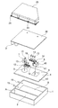
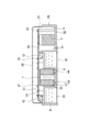
- FIG. 1 is a plan sectional view showing a main part of an in-vehicle power conversion device according to Embodiment 1 of the present invention. It is arrow sectional drawing along the II-II line of the vehicle-mounted power converter device of FIG. It is a disassembled perspective view which shows the vehicle-mounted power converter device of FIG. It is a sectional side view which shows the vehicle-mounted power converter device of Embodiment 2 of this invention. It is a disassembled perspective view which shows the principal part of the vehicle-mounted power converter device of FIG.
- FIG. 1 is a plan sectional view showing a main part (under the circuit board 20) of an in-vehicle power converter (hereinafter referred to as a power converter) according to Embodiment 1 of the present invention
- FIG. FIG. 3 is an exploded perspective view showing the power conversion device of FIG. 1 when the power conversion device including the circuit board 20 and the cover 25 is cut along the line II-II.
- the power conversion device is mounted on a plug-in hybrid vehicle, an electric vehicle or the like, and converts a AC input power source into a direct current to charge a high voltage battery, and converts the voltage of the high voltage battery to a 12V system voltage. It is a power converter such as a DCDC converter that converts and charges an auxiliary battery.
- the case 1 made of aluminum, which is the second metal member, opened on the upper side is divided into two by the first wall 2.
- a capacitor 3 is accommodated in one of the first spaces A partitioned by the first wall 2.
- the other second space B is covered with an aluminum lid 4 that is a first metal member to form a sealed space.
- the lid 4 is formed with a first recess 5 and a second recess 6 that are spaced apart from each other.
- the first recess 5 houses a reactor body 7 that is a heat generating electrical component body.
- the second recess 6 houses a transformer main body 8 having a core 40 and a coil 41, which is a heat generating electric component main body.
- the first recess 5 is filled with an insulating resin 10 which is a resin such as silicon, and the reactor body 7 is fixed.
- the reactor body 7 is held by the resin holder 9, and the leg portion 44 of the resin holder 9 is fitted in the groove portion 45 of the lid 4 and positioned at the center of the first recess 5.
- the transformer body 8 in the second recess 6 is positioned at the center of the second recess 6 by a resin holder (not shown), and is an insulating material such as a resin such as silicon filled in the second recess 6. It is fixed with resin 11.
- a resin holder not shown
- a plurality of semiconductor components 12 that perform high-frequency switching operations facing each other are secured by the fixing screws 13 via the heat dissipation sheet 42. It is fixed.
- a second wall 14 connecting the first recess 5 and the second recess 6 is formed on the back surface side of the lid 4, and this second wall 14 allows U to enter the second space B.
- a letter-shaped refrigerant passage 50 is formed.
- the end portion of the inflow pipe 15 passes through the side surface of the case 1, and the ethylene glycol liquid that is a refrigerant flows into the second space B through the inflow pipe 15. Further, the end portion of the outflow pipe 16 passes through the side surface of the case 1, and the ethylene glycol liquid in the second space B flows out through the outflow pipe 16.
- the reactor terminal 17 of the reactor body 7, the transformer terminal 18 of the transformer body 8, and the semiconductor terminal 19 of the semiconductor component 12 have their tips extending in a direction perpendicular to the flat surface 43 of the lid 4, and the back side of the circuit board 20. It is inserted from the surface and joined by soldering or laser welding.
- the circuit board 20 is fixed to the first boss 21 extending in the vertical direction from the surface of the lid 4 and the second boss 22 extending in the vertical direction from the surface of the case 1.
- 23 is fixed. 1 and 3, the first boss 21 and the second boss 22 are omitted.
- a cover 25 is provided on the upper side of the circuit board 20. The cover 25 is fixed to the case 1 and the lid 4 with fixing screws 24 at the peripheral edge thereof.
- the lid 4 that is the first metal member is formed with a pair of first recesses 5 and second recesses 6 that protrude into the second space B, and the first recesses are respectively formed.
- a reactor main body 7 which is a heat generating electric component main body is accommodated in 5
- a transformer main body 8 which is a heat generating electric component main body is accommodated in the second recess 6.
- an ethylene glycol liquid as a refrigerant flows from the inflow pipe 15, passes through the refrigerant passage 50, and flows out from the outflow pipe 16 to the outside.
- the reactor body 7 and the transformer body 8 are surrounded by the ethylene glycol liquid through the recesses 5 and 6 of the aluminum lid 4 having high thermal conductivity, a sufficient heat radiation area is secured. Since ethylene glycol liquid is flowing and heat transfer is increased, heat is efficiently radiated.
- the reactor main body 7 in the first recess 5 and the transformer main body 8 in the second recess 6 are simply fixed by the filled insulating resins 10 and 11, respectively, and a part of the lid 4 is respectively a reactor. Since the reactor 7 and the transformer body 8 are housed in the main body 7 and the transformer main body 8, the number of parts is reduced and the heat transfer path between the ethylene glycol liquid and the reactor main body 7 and the transformer main body 8 is shortened. And reduced to a thermal resistance value.
- the lid 4 having the first recess 5 and the second recess 6 has a plurality of semiconductor components 12 that perform high-frequency switching operation mounted on the flat surface 43 on the surface side thereof, so that the electrical power on the circuit board 20 is increased accordingly.
- the mounting area of components can be reduced.
- the back side of the lid 4 on which the semiconductor component 12 is mounted is the second space B, and the semiconductor component 12 is efficiently radiated through the ethylene glycol liquid flowing in the second space B, so that the circuit Thermal interference with other electrical components on the substrate 20 can be further suppressed, and the power converter can be downsized.
- the reactor main body 7 in the first concave portion 5 and the transformer main body 8 in the second concave portion 6 are easily positioned at the centers of the concave portions 5 and 6 by the resin holder 9, respectively, so that the assembly workability is improved. Will improve.
- the reactor terminal 17 of the reactor main body 7, the transformer terminal 18 of the transformer main body 8, and the semiconductor terminal 19 of the semiconductor component 12 have their tips extending in the vertical direction from the flat surface 43 of the lid 4, so that the circuit board 20 And assembly reliability and assembly reliability are improved. Further, by directly assembling the reactor terminal 17 of the reactor body 7, the transformer terminal 18 of the transformer body 8, and the semiconductor terminal 19 of the semiconductor component 12 to the circuit board 20, the number of components can be reduced and the distance of the wiring through which a large current flows. Can be minimized. Thereby, the influence on the circuit board 20 of the electrical noise which generate
- the direction in which the reactor body 7 is embedded in the first recess 5 of the lid 4 and the direction in which the transformer body 8 is embedded in the second recess 6 of the lid 4 are the directions in which the semiconductor component 12 is mounted on the flat surface 43 of the lid 4.
- the resin holder 9 attached to the reactor body 7 and the resin holder (not shown) attached to the transformer body 8 positioning with respect to the circuit board 20 becomes easy. Thereby, an assembling property improves.
- the first recess 5 and the second recess 6 are connected by the second wall 14, and the ethylene glycol liquid enters from the inflow pipe 15 and flows out through the outflow pipe 16.
- the reactor body 7 embedded in the first recess 5 and the transformer body 8 embedded in the second recess 6 are reliably cooled by the ethylene glycol liquid flowing in the forward path and the return path.
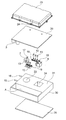
- FIG. 4 is a side sectional view showing a power conversion apparatus according to Embodiment 2 of the present invention
- FIG. 5 is an exploded perspective view of FIG.
- the aluminum case 30 as the first metal member has a bottom portion 32 in which the capacitor 3 is housed in the first space A and a protruding portion 31 protruding upward.
- the bottom surface of the protruding portion 31 of the case 30 is covered with an aluminum lid 35 that is a second metal member, and the second space B inside the protruding portion 31 is sealed by the lid 35.
- the protrusion 31 is formed with a first recess 33 and a second recess 34 that are spaced apart from each other.
- the reactor main body 7 is accommodated in the first recess 33.
- a transformer body 8 having a core 40 and a coil 41 is accommodated in the second recess 34.
- the reactor body 7 in the first recess 33 is positioned at the center of the first recess 33 by the resin holder 9 and is fixed by the insulating resin 10 filled in the first recess 33.
- the transformer main body 8 in the second recess 34 is positioned at the center of the second recess 34 by a resin holder (not shown), and is fixed by an insulating resin filled in the second recess 34. .
- a plurality of semiconductor components 12 are fixed to the surface of the protruding portion 31 of the case 30 with fixing screws 13 via a heat dissipation sheet (not shown).
- a wall (not shown) that connects the first recess 33 and the second recess 34 is formed in the second space B inside the protrusion 31, and this wall allows the interior of the protrusion 31 to be formed.
- a U-shaped refrigerant passage 50 is formed in the second space B.
- Other configurations are the same as those of the power conversion apparatus according to the first embodiment.
- the reactor main body 7 and the transformer main body 8 are surrounded by the second space B in which the outer periphery of each of the reactor main body 7 and the transformer main body 8 flows. It can be secured greatly.
- the semiconductor component 12 is mounted on a flat surface 43 on which the first concave portion 33 and the second concave portion 34 are formed, and the heat of the semiconductor component 12 is ethylene glycol through the heat dissipation sheet and the flat surface 43 of the case 30. The heat is dissipated by being transmitted to the liquid, and the heat dissipation of the semiconductor component 12 is improved.
- the semiconductor component 12, the reactor main body 7, the transformer main body 8, and the capacitor 3 are arranged in a space closed by the case 30 and the cover 25, and the ethylene glycol liquid in the second space B is covered with a cover outside the case 30. Therefore, even if the ethylene glycol liquid in the second space B leaks from the joint portion between the case 30 and the lid 35, it does not flow into the power converter. Accordingly, it is possible to avoid the occurrence of problems such as short circuit and poor lead due to the ethylene glycol liquid adhering to the semiconductor component 12, the reactor main body 7, the transformer main body 8, the capacitor 3, and the like.
- the refrigerant passage 50 is a U-shaped passage in the second space B, but may be an I passage through which the refrigerant flows in one direction.
Landscapes
- Engineering & Computer Science (AREA)
- Microelectronics & Electronic Packaging (AREA)
- Power Engineering (AREA)
- Transportation (AREA)
- Mechanical Engineering (AREA)
- Physics & Mathematics (AREA)
- Thermal Sciences (AREA)
- Life Sciences & Earth Sciences (AREA)
- Sustainable Development (AREA)
- Sustainable Energy (AREA)
- Dc-Dc Converters (AREA)
- Inverter Devices (AREA)
Description
また、フィンから放熱される熱により、装置内部の温度が上昇するという問題点があった。
しかも、第1の金属部品の凹部がそれぞれ発熱電気部品本体を収納した、発熱電気部品の容器を兼ねているので、部品点数が削減されるとともに、冷媒と、発熱電気部品本体との間の熱伝達経路が短縮化され、熱抵抗値に低減される。
実施の形態1.
図1はこの発明の実施の形態1の車載用電力変換装置(以下、電力変換装置と呼ぶ。)の主要部(回路基板20の下側)を示す平断面図、図2は図1のものに回路基板20及びカバー25を加えた電力変装置をII-II線に沿って切断したときの矢視断面図、図3は図1の電力変換装置を示す分解斜視図である。
この発明の電力変換装置は、プラグインハイブリッド車、電気自動車等に搭載され、AC入力電源を直流に変換して高電圧バッテリに充電する充電器や、高電圧バッテリの電圧を、12V系電圧に変換して補機バッテリを充電するDCDCコンバータ等の電力変換装置である。
この電力変換装置では、上側が開放した、第2の金属部材であるアルミニウム製のケース1は、内部が第1の壁2で2分割されている。第1の壁2で区画された一方の第1の空間Aには、コンデンサ3が収納されている。他方の第2の空間Bは、第1の金属部材であるアルミニウム製の蓋4で覆われて密閉された空間を形成している。
第1の凹部5内には、シリコン等の樹脂である絶縁樹脂10が充填されてリアクトル本体7が固定されている。
このリアクトル本体7は、樹脂ホルダ9で保持されているとともに、樹脂ホルダ9の脚部44が蓋4の溝部45に嵌着されて第1の凹部5の中心に位置決めされている。
第2の凹部6内のトランス本体8は、樹脂ホルダ(図示せず)により、第2の凹部6の中心に位置決めされ、また第2の凹部6内に充填されたシリコン等の樹脂である絶縁樹脂11で固定されている。
第1の凹部5と第2の凹部6との間であって、蓋4の平面43には、互いに対向した高周波スイッチング動作を行う複数の半導体部品12が放熱シート42を介して固定ねじ13で固定されている。
ケース1の側面には、流入配管15の先端部が貫通しており、この流入配管15を通じて第2の空間Bには、冷媒であるエチレングリコール液が流入する。また、ケース1の側面には、流出配管16の先端部が貫通しており、この流出配管16を通じて第2の空間B内のエチレングリコール液が外部に流出する。
回路基板20は、図2に示すように、蓋4の表面から垂直方向に延設された第1のボス21、ケース1の表面から垂直方向に延設された第2のボス22に固定ねじ23で固定されている。なお、図1及び図3では、第1のボス21及び第2のボス22は、省略されている。
回路基板20の上側には、カバー25が設けられている。このカバー25は、その周縁部の固定ねじ24で、ケース1及び蓋4に固定されている。
この第2の空間B内には、流入配管15から冷媒であるエチレングリコール液が流入し、冷媒通路50を通過して流出配管16から外部に流出する。
従って、リアクトル本体7及びトランス本体8は、周囲が熱伝導性の高いアルミニウム製の蓋4の凹部5,6を介してエチレングリコール液で囲まれているので、放熱面積が充分に確保され、しかもエチレングリコール液は流動しており、熱伝達が増加するので、効率よく放熱される。
また、半導体部品12が搭載された蓋4の裏側は、第2の空間Bであり、半導体部品12は、この第2の空間B内を流通するエチレングリコール液を通じて効率よく放熱されるので、回路基板20上の他の電気部品への熱干渉をより抑制することができ、電力変換装置を小型化することができる。
また、リアクトル本体7のリアクトル端子17、トランス本体8のトランス端子18及び半導体部品12の半導体端子19を直接回路基板20に組付けることで、部品点数が削減できるとともに、大電流が流れる配線の距離を最短化できる。
これにより、熱損失、及び高周波駆動する際に発生する、電気的なノイズの回路基板20への影響を抑制することができる。
これにより、組付性が向上する。
図4はこの発明の実施の形態2の電力変換装置を示す側断面図、図5は図4の分解斜視図である。
この発明の電力変換装置では、第1の金属部材であるアルミニウム製のケース30は、第1の空間A内にコンデンサ3が収納された底部32及び上側に突出した突出部31を有している。ケース30の突出部31の底面は、第2の金属部材であるアルミニウム製の蓋35で覆われており、突出部31の内部の第2の空間Bは、この蓋35により密閉されている。
第1の凹部33内のリアクトル本体7は、樹脂ホルダ9により、第1の凹部33の中心に位置決めされ、また第1の凹部33内に充填された絶縁樹脂10により固定されている。
第2の凹部34内のトランス本体8は、樹脂ホルダ(図示せず)により、第2の凹部34の中心に位置決めされ、また第2の凹部34内に充填された絶縁樹脂により固定されている。
ケース30の突出部31の表面には、放熱シート(図示せず)を介して複数の半導体部品12が固定ねじ13で固定されている。
突出部31の内部の第2の空間Bには、第1の凹部33と第2の凹部34とを接続する壁(図示せず)が形成されており、この壁により、突出部31の内部の第2の空間BにはU字状の冷媒通路50が形成されている。
他の構成は、実施の形態1の電力変換装置と同じである。
また、第1の凹部33及び第2の凹部34を形成した表面側の平面43に、半導体部品12が搭載されており、半導体部品12の熱は、放熱シート及びケース30の平面43を通じてエチレングリコール液に伝達されて放熱され、半導体部品12の放熱性が向上する。
従って、半導体部品12、リアクトル本体7、トランス本体8、コンデンサ3等にエチレングリコール液が付着してショート、導線不良等の不具合が生じるのを回避することができる。
また、冷媒通路50は、第2の空間B内にU字路であるが、一方向に冷媒が流れるI通路であってもよい。
Claims (8)
- 第1の金属部材と、
この第1の金属部材と接合して冷媒が流通する空間を形成した第2の金属部材と、
前記第1の金属部材に前記空間の内部に突出して形成された凹部に収納された発熱電気部品本体と、
を備えたことを特徴とする電力変換装置。 - 前記第1の金属部材は、前記凹部を形成した平面に高周波スイッチング動作を行う半導体部品が搭載されていることを特徴とする請求項1に記載の電力変換装置。
- 前記発熱電気部品本体及び前記半導体部品は、それぞれの端子の先端部が前記平面に対して垂直方向に延出していることを特徴とする請求項2に記載の電力変換装置。
- 前記平面に対向して、回路基板が配設されており、この回路基板には、前記端子が電気的に接続されていることを特徴とする請求項3に記載の電力変換装置。
- 前記発熱電気部品本体は、前記凹部に充填された絶縁樹脂により凹部内に固定されていることを特徴とする請求項1~4の何れか1項に記載の電力変換装置。
- 前記発熱電気部品本体は、前記発熱電気部品本体を保持した樹脂ホルダにより、前記凹部の中心に位置決めされていることを特徴とする請求項1~5の何れか1項に記載の電力変換装置。
- 前記凹部は、離間して一対形成されており、
それぞれの前記凹部間は、前記冷媒の往路と復路とを区分けする壁で接続されており、
前記空間内と連通した流入配管から流入した前記冷媒は、前記復路及び前記復路を通り、前記空間内と連通した流出配管から外部に流出することを特徴とする請求項1~6の何れか1項に記載の電力変換装置。 - 前記電力変換装置は、車載用電力変換装置であり、
一方の前記凹部には、前記発熱電気部品本体であるリアクトル本体が収納されており、 他方の前記凹部には、前記発熱電気部品本体であるトランス本体が収納されていることを特徴とする請求項7に記載の電力変換装置。
Priority Applications (5)
| Application Number | Priority Date | Filing Date | Title |
|---|---|---|---|
| PCT/JP2012/057034 WO2013140502A1 (ja) | 2012-03-19 | 2012-03-19 | 電力変換装置 |
| EP12871882.2A EP2830073B1 (en) | 2012-03-19 | 2012-03-19 | Power conversion apparatus |
| JP2014505833A JP5823020B2 (ja) | 2012-03-19 | 2012-03-19 | 電力変換装置 |
| US14/372,664 US9578790B2 (en) | 2012-03-19 | 2012-03-19 | Power conversion apparatus |
| CN201280071613.3A CN104205260B (zh) | 2012-03-19 | 功率转换装置 |
Applications Claiming Priority (1)
| Application Number | Priority Date | Filing Date | Title |
|---|---|---|---|
| PCT/JP2012/057034 WO2013140502A1 (ja) | 2012-03-19 | 2012-03-19 | 電力変換装置 |
Publications (1)
| Publication Number | Publication Date |
|---|---|
| WO2013140502A1 true WO2013140502A1 (ja) | 2013-09-26 |
Family
ID=49221996
Family Applications (1)
| Application Number | Title | Priority Date | Filing Date |
|---|---|---|---|
| PCT/JP2012/057034 Ceased WO2013140502A1 (ja) | 2012-03-19 | 2012-03-19 | 電力変換装置 |
Country Status (4)
| Country | Link |
|---|---|
| US (1) | US9578790B2 (ja) |
| EP (1) | EP2830073B1 (ja) |
| JP (1) | JP5823020B2 (ja) |
| WO (1) | WO2013140502A1 (ja) |
Cited By (15)
| Publication number | Priority date | Publication date | Assignee | Title |
|---|---|---|---|---|
| JP2015103800A (ja) * | 2013-11-26 | 2015-06-04 | 台達電子企業管理(上海)有限公司 | 放熱ベースと電子装置 |
| JP2015103816A (ja) * | 2013-11-26 | 2015-06-04 | 台達電子企業管理(上海)有限公司 | 電子装置と自動車の充電装置 |
| JP2016171709A (ja) * | 2015-03-13 | 2016-09-23 | 株式会社豊田自動織機 | 送電機器 |
| JP2017055521A (ja) * | 2015-09-08 | 2017-03-16 | Tdk株式会社 | 電源装置 |
| JP2017175165A (ja) * | 2013-11-26 | 2017-09-28 | 台達電子企業管理(上海)有限公司 | 電源変換装置及びその組立方法 |
| WO2017187478A1 (ja) * | 2016-04-25 | 2017-11-02 | 三菱電機株式会社 | 電力変換装置 |
| WO2017187479A1 (ja) * | 2016-04-25 | 2017-11-02 | 三菱電機株式会社 | 車載充電器およびその製造方法 |
| WO2019208250A1 (ja) * | 2018-04-25 | 2019-10-31 | パナソニックIpマネジメント株式会社 | 電源装置 |
| JP2020022288A (ja) * | 2018-08-01 | 2020-02-06 | 株式会社デンソー | 電力変換装置 |
| KR20220020002A (ko) * | 2020-08-11 | 2022-02-18 | 센서나인(주) | 고전압 트랜스포머 |
| US20220346286A1 (en) * | 2021-04-22 | 2022-10-27 | Hyundai Motor Company | Power inverter |
| JP2024075654A (ja) * | 2020-06-10 | 2024-06-04 | パナソニックオートモーティブシステムズ株式会社 | 車載充電器およびインバータ |
| DE102015218071B4 (de) | 2014-11-05 | 2024-11-07 | Hyundai Motor Company | Seite Induktorvorrichtung für ein Fahrzeug |
| JP2025024071A (ja) * | 2020-07-09 | 2025-02-19 | ビーワイディー カンパニー リミテッド | 車載電源装置及びそれを有する車両 |
| US12278450B2 (en) | 2019-07-25 | 2025-04-15 | ABB E-mobility B.V. | Vehicle charging system for charging an electrical vehicle |
Families Citing this family (29)
| Publication number | Priority date | Publication date | Assignee | Title |
|---|---|---|---|---|
| JP6045340B2 (ja) * | 2012-12-28 | 2016-12-14 | 日立オートモティブシステムズ株式会社 | Dc−dcコンバータ装置 |
| DE102014217552A1 (de) * | 2014-09-03 | 2016-03-03 | Conti Temic Microelectronic Gmbh | Steuergerätevorrichtung für ein Kraftfahrzeug sowie Verfahren zum Herstellen einer solchen |
| JP6459418B2 (ja) * | 2014-11-13 | 2019-01-30 | 富士電機株式会社 | 半導体装置およびその製造方法 |
| JP6488194B2 (ja) * | 2015-05-26 | 2019-03-20 | 株式会社日立製作所 | 電源装置 |
| JP6471050B2 (ja) * | 2015-06-17 | 2019-02-13 | 本田技研工業株式会社 | 電動車両 |
| CN106655710B (zh) | 2015-10-29 | 2019-02-22 | 台达电子企业管理(上海)有限公司 | 电源转换装置 |
| CN106655806B (zh) * | 2015-10-29 | 2019-02-26 | 台达电子企业管理(上海)有限公司 | 电源转换装置 |
| JP6710283B2 (ja) * | 2016-09-20 | 2020-06-17 | 三菱電機株式会社 | 電力変換装置 |
| EP3608957A4 (en) | 2017-04-03 | 2020-04-08 | Mitsubishi Electric Corporation | CONTROL UNIT DRIVE UNIT |
| CN108336892B (zh) * | 2017-05-25 | 2021-11-16 | 泰达电子股份有限公司 | 电源模块及其组装结构与组装方法 |
| JP2019033624A (ja) * | 2017-08-09 | 2019-02-28 | 株式会社デンソー | 電力変換装置 |
| CN108076617B (zh) * | 2018-01-04 | 2021-02-02 | 深圳威迈斯新能源股份有限公司 | 用于车载充电机或电压变换器的散热结构 |
| JP6509414B1 (ja) | 2018-07-30 | 2019-05-08 | 三菱電機株式会社 | 電力変換装置 |
| JP6541859B1 (ja) | 2018-11-01 | 2019-07-10 | 三菱電機株式会社 | 電力変換装置 |
| US11855528B2 (en) * | 2018-12-26 | 2023-12-26 | Panasonic Intellectual Property Management Co., Ltd. | Power conversion apparatus |
| JP7620567B2 (ja) * | 2019-04-19 | 2025-01-23 | メタ システム エス.ピー.エー. | 電気車両またはハイブリッド車両の電子電力変換装置 |
| US11670443B2 (en) * | 2019-11-18 | 2023-06-06 | Ford Global Technologies, Llc | Liquid cooled inductor via nozzle spray |
| JP7304540B2 (ja) * | 2019-12-12 | 2023-07-07 | パナソニックIpマネジメント株式会社 | 電力変換装置、及び電力変換装置の製造方法 |
| KR20220099022A (ko) * | 2021-01-05 | 2022-07-12 | 엘지이노텍 주식회사 | 컨버터 |
| JP7366077B2 (ja) * | 2021-03-09 | 2023-10-20 | 三菱電機株式会社 | 電力変換装置 |
| CN113079678A (zh) * | 2021-03-29 | 2021-07-06 | 阳光电源股份有限公司 | 液冷散热装置及功率模块 |
| AT525115B1 (de) * | 2021-06-10 | 2025-05-15 | Avl List Gmbh | Elektronikvorrichtung für eine Leistungselektronik einer elektrischen Antriebsvorrichtung eines Fahrzeugs |
| CN116437624A (zh) * | 2022-01-11 | 2023-07-14 | 开利公司 | 机械封壳 |
| JP7180805B1 (ja) * | 2022-03-08 | 2022-11-30 | 富士電機株式会社 | 電力変換装置および直流直流コンバータ装置 |
| JP7439155B2 (ja) * | 2022-03-25 | 2024-02-27 | 本田技研工業株式会社 | 電力変換装置 |
| FR3157055B1 (fr) * | 2023-12-13 | 2026-02-13 | Sogefi Air & Cooling | Module électronique de puissance, son procédé de fabrication et véhicule comportant un tel module |
| CN222302247U (zh) * | 2024-03-05 | 2025-01-03 | 华为数字能源技术有限公司 | 功率模组和充电设备 |
| CN120980829A (zh) * | 2024-05-16 | 2025-11-18 | 法雷奥新能源汽车德国有限责任公司 | 电气装置、电驱动系统和车辆 |
| DE102024208601A1 (de) * | 2024-09-10 | 2026-03-12 | Robert Bosch Gesellschaft mit beschränkter Haftung | Kühleranordnung |
Citations (5)
| Publication number | Priority date | Publication date | Assignee | Title |
|---|---|---|---|---|
| JPH08149621A (ja) * | 1994-11-18 | 1996-06-07 | Sansha Electric Mfg Co Ltd | 密閉型電源冷却装置 |
| JP2002050527A (ja) | 2000-07-31 | 2002-02-15 | Honda Motor Co Ltd | 冷却装置付きリアクトル |
| JP2010135369A (ja) * | 2008-12-02 | 2010-06-17 | Denso Corp | リアクトル |
| JP2011151193A (ja) * | 2010-01-21 | 2011-08-04 | Toyota Motor Corp | 冷却器 |
| JP2011228508A (ja) * | 2010-04-21 | 2011-11-10 | Toyota Motor Corp | パワーモジュール |
Family Cites Families (29)
| Publication number | Priority date | Publication date | Assignee | Title |
|---|---|---|---|---|
| US5159529A (en) * | 1991-05-15 | 1992-10-27 | International Business Machines Corporation | Composite liquid cooled plate for electronic equipment |
| JP3066726B2 (ja) | 1995-11-08 | 2000-07-17 | 富士通電装株式会社 | 半導体装置の取付け構造 |
| JP4218184B2 (ja) | 2000-05-19 | 2009-02-04 | 株式会社デンソー | 半導体装置の実装構造 |
| JP2002198477A (ja) | 2000-12-25 | 2002-07-12 | Toyota Motor Corp | 半導体装置 |
| JP3946018B2 (ja) * | 2001-09-18 | 2007-07-18 | 株式会社日立製作所 | 液冷却式回路装置 |
| US6865080B2 (en) * | 2002-01-16 | 2005-03-08 | Rockwell Automation Technologies, Inc. | Compact fluid cooled power converter supporting multiple circuit boards |
| JP4003719B2 (ja) | 2003-08-22 | 2007-11-07 | 株式会社デンソー | 電力変換装置 |
| JP4154325B2 (ja) * | 2003-12-19 | 2008-09-24 | 株式会社日立産機システム | 電気回路モジュール |
| JP2005229033A (ja) * | 2004-02-16 | 2005-08-25 | Hitachi Ltd | 液冷システムおよびそれを備えた電子機器 |
| US20080117602A1 (en) * | 2006-11-20 | 2008-05-22 | Korich Mark D | Power inverter having liquid cooled capacitor and low inductance bus structure |
| US7710723B2 (en) * | 2007-07-17 | 2010-05-04 | Gm Global Technology Operations, Inc. | Vehicle inverter assembly with cooling channels |
| JP4819071B2 (ja) * | 2008-02-06 | 2011-11-16 | 本田技研工業株式会社 | 電気車両及び車両用dc/dcコンバータの冷却方法 |
| JP4580997B2 (ja) * | 2008-03-11 | 2010-11-17 | 日立オートモティブシステムズ株式会社 | 電力変換装置 |
| US8169780B2 (en) * | 2009-06-18 | 2012-05-01 | Honda Motor Co., Ltd. | Power conversion device |
| US8064198B2 (en) * | 2009-06-29 | 2011-11-22 | Honda Motor Co., Ltd. | Cooling device for semiconductor element module and magnetic part |
| JP5099086B2 (ja) | 2009-07-28 | 2012-12-12 | 株式会社デンソー | 電源装置 |
| US8570132B2 (en) | 2009-10-27 | 2013-10-29 | GM Global Technology Operations LLC | Power electronics assembly with multi-sided inductor cooling |
| JP5422466B2 (ja) * | 2010-04-01 | 2014-02-19 | 日立オートモティブシステムズ株式会社 | 電力変換装置 |
| JP5618595B2 (ja) * | 2010-04-01 | 2014-11-05 | 日立オートモティブシステムズ株式会社 | パワーモジュール、およびパワーモジュールを備えた電力変換装置 |
| JP5380376B2 (ja) * | 2010-06-21 | 2014-01-08 | 日立オートモティブシステムズ株式会社 | パワー半導体装置 |
| JP5563383B2 (ja) * | 2010-06-21 | 2014-07-30 | 日立オートモティブシステムズ株式会社 | 電力変換装置 |
| DE102010043446B3 (de) * | 2010-11-05 | 2012-01-12 | Semikron Elektronik Gmbh & Co. Kg | Leistungshalbleitersystem |
| JP2012174856A (ja) * | 2011-02-21 | 2012-09-10 | Hitachi Cable Ltd | ヒートシンク及びその製造方法 |
| JP5506741B2 (ja) * | 2011-06-02 | 2014-05-28 | 日立オートモティブシステムズ株式会社 | 電力変換装置 |
| JP5502805B2 (ja) * | 2011-06-08 | 2014-05-28 | 日立オートモティブシステムズ株式会社 | パワーモジュールおよびそれを用いた電力変換装置 |
| EP2787529B1 (en) | 2011-11-30 | 2018-05-23 | Mitsubishi Electric Corporation | Semiconductor device, and on-board power conversion device |
| JP5783212B2 (ja) * | 2013-09-06 | 2015-09-24 | Tdk株式会社 | 電源装置 |
| CN104684338B (zh) * | 2013-11-26 | 2018-01-30 | 台达电子企业管理(上海)有限公司 | 散热基座与电子装置 |
| US9362040B2 (en) * | 2014-05-15 | 2016-06-07 | Lear Corporation | Coldplate with integrated electrical components for cooling thereof |
-
2012
- 2012-03-19 US US14/372,664 patent/US9578790B2/en active Active
- 2012-03-19 EP EP12871882.2A patent/EP2830073B1/en active Active
- 2012-03-19 JP JP2014505833A patent/JP5823020B2/ja active Active
- 2012-03-19 WO PCT/JP2012/057034 patent/WO2013140502A1/ja not_active Ceased
Patent Citations (5)
| Publication number | Priority date | Publication date | Assignee | Title |
|---|---|---|---|---|
| JPH08149621A (ja) * | 1994-11-18 | 1996-06-07 | Sansha Electric Mfg Co Ltd | 密閉型電源冷却装置 |
| JP2002050527A (ja) | 2000-07-31 | 2002-02-15 | Honda Motor Co Ltd | 冷却装置付きリアクトル |
| JP2010135369A (ja) * | 2008-12-02 | 2010-06-17 | Denso Corp | リアクトル |
| JP2011151193A (ja) * | 2010-01-21 | 2011-08-04 | Toyota Motor Corp | 冷却器 |
| JP2011228508A (ja) * | 2010-04-21 | 2011-11-10 | Toyota Motor Corp | パワーモジュール |
Non-Patent Citations (1)
| Title |
|---|
| See also references of EP2830073A4 |
Cited By (31)
| Publication number | Priority date | Publication date | Assignee | Title |
|---|---|---|---|---|
| JP2015103800A (ja) * | 2013-11-26 | 2015-06-04 | 台達電子企業管理(上海)有限公司 | 放熱ベースと電子装置 |
| JP2015103816A (ja) * | 2013-11-26 | 2015-06-04 | 台達電子企業管理(上海)有限公司 | 電子装置と自動車の充電装置 |
| US9655288B2 (en) | 2013-11-26 | 2017-05-16 | Delta Electronics (Shanghai) Co., Ltd. | Electronic device and car battery charger |
| JP2017126776A (ja) * | 2013-11-26 | 2017-07-20 | 台達電子企業管理(上海)有限公司 | 放熱ベースと電子装置 |
| JP2017175165A (ja) * | 2013-11-26 | 2017-09-28 | 台達電子企業管理(上海)有限公司 | 電源変換装置及びその組立方法 |
| DE102015218071B8 (de) | 2014-11-05 | 2025-01-09 | Hyundai Motor Company | Induktorvorrichtung für ein Fahrzeug |
| DE102015218071B4 (de) | 2014-11-05 | 2024-11-07 | Hyundai Motor Company | Seite Induktorvorrichtung für ein Fahrzeug |
| JP2016171709A (ja) * | 2015-03-13 | 2016-09-23 | 株式会社豊田自動織機 | 送電機器 |
| JP2017055521A (ja) * | 2015-09-08 | 2017-03-16 | Tdk株式会社 | 電源装置 |
| WO2017187478A1 (ja) * | 2016-04-25 | 2017-11-02 | 三菱電機株式会社 | 電力変換装置 |
| WO2017187479A1 (ja) * | 2016-04-25 | 2017-11-02 | 三菱電機株式会社 | 車載充電器およびその製造方法 |
| JPWO2017187478A1 (ja) * | 2016-04-25 | 2018-08-09 | 三菱電機株式会社 | 電力変換装置 |
| JP2024091990A (ja) * | 2018-04-25 | 2024-07-05 | パナソニックオートモーティブシステムズ株式会社 | 電源装置および電力変換装置 |
| JPWO2019208250A1 (ja) * | 2018-04-25 | 2021-05-27 | パナソニックIpマネジメント株式会社 | 電源装置 |
| WO2019208250A1 (ja) * | 2018-04-25 | 2019-10-31 | パナソニックIpマネジメント株式会社 | 電源装置 |
| JP7483963B2 (ja) | 2018-04-25 | 2024-05-15 | パナソニックオートモーティブシステムズ株式会社 | 電源装置 |
| JP2023053038A (ja) * | 2018-04-25 | 2023-04-12 | パナソニックIpマネジメント株式会社 | 電源装置 |
| JP7233026B2 (ja) | 2018-04-25 | 2023-03-06 | パナソニックIpマネジメント株式会社 | 電源装置 |
| JP7073969B2 (ja) | 2018-08-01 | 2022-05-24 | 株式会社デンソー | 電力変換装置 |
| JP2020022288A (ja) * | 2018-08-01 | 2020-02-06 | 株式会社デンソー | 電力変換装置 |
| US12278450B2 (en) | 2019-07-25 | 2025-04-15 | ABB E-mobility B.V. | Vehicle charging system for charging an electrical vehicle |
| JP2024075654A (ja) * | 2020-06-10 | 2024-06-04 | パナソニックオートモーティブシステムズ株式会社 | 車載充電器およびインバータ |
| JP7823246B2 (ja) | 2020-06-10 | 2026-03-03 | パナソニックオートモーティブシステムズ株式会社 | 車載充電器およびインバータ |
| JP2025083416A (ja) * | 2020-06-10 | 2025-05-30 | パナソニックオートモーティブシステムズ株式会社 | 車載充電器およびインバータ |
| JP7649898B2 (ja) | 2020-06-10 | 2025-03-21 | パナソニックオートモーティブシステムズ株式会社 | 車載充電器およびインバータ |
| JP7788525B2 (ja) | 2020-07-09 | 2025-12-18 | ビーワイディー カンパニー リミテッド | 車載電源装置及びそれを有する車両 |
| JP2025024071A (ja) * | 2020-07-09 | 2025-02-19 | ビーワイディー カンパニー リミテッド | 車載電源装置及びそれを有する車両 |
| KR20220020002A (ko) * | 2020-08-11 | 2022-02-18 | 센서나인(주) | 고전압 트랜스포머 |
| KR102385919B1 (ko) | 2020-08-11 | 2022-04-18 | 센서나인(주) | 고전압 트랜스포머 |
| US12150286B2 (en) * | 2021-04-22 | 2024-11-19 | Hyundai Motor Company | Power inverter with extrusion cooler with flow holes |
| US20220346286A1 (en) * | 2021-04-22 | 2022-10-27 | Hyundai Motor Company | Power inverter |
Also Published As
| Publication number | Publication date |
|---|---|
| EP2830073A1 (en) | 2015-01-28 |
| US9578790B2 (en) | 2017-02-21 |
| US20150208556A1 (en) | 2015-07-23 |
| CN104205260A (zh) | 2014-12-10 |
| EP2830073B1 (en) | 2017-09-13 |
| JP5823020B2 (ja) | 2015-11-25 |
| EP2830073A4 (en) | 2015-11-18 |
| JPWO2013140502A1 (ja) | 2015-08-03 |
Similar Documents
| Publication | Publication Date | Title |
|---|---|---|
| JP5823020B2 (ja) | 電力変換装置 | |
| JP5535292B2 (ja) | 電力変換装置 | |
| US9750147B2 (en) | Power converter | |
| US11682516B2 (en) | Reactor cooling structure | |
| US11864362B2 (en) | Power supply device with a heat generating component | |
| JP6180857B2 (ja) | 電力変換装置 | |
| JP6945671B2 (ja) | 電力変換装置 | |
| US9992915B2 (en) | Power conversion device | |
| WO2014103614A1 (ja) | Dc-dcコンバータ装置 | |
| JP5783212B2 (ja) | 電源装置 | |
| WO2013061799A1 (ja) | 電力変換装置 | |
| WO2014020806A1 (ja) | 冷却構造体及び電力変換装置 | |
| JP4937326B2 (ja) | パワーモジュール | |
| US12021459B2 (en) | Power conversion device | |
| JP2010087002A (ja) | 発熱部品冷却構造 | |
| US20140284028A1 (en) | Cooler | |
| WO2018110275A1 (ja) | 電気接続箱 | |
| JP2015167069A (ja) | 蓄電モジュール | |
| JP2019170158A (ja) | 電力変換装置 | |
| JP7081525B2 (ja) | 電力変換装置 | |
| CN104205260B (zh) | 功率转换装置 | |
| JP6200716B2 (ja) | 積層構造体および積層ユニット | |
| JP2024020757A (ja) | 電力変換装置 | |
| JP2016092868A (ja) | 積層ユニット |
Legal Events
| Date | Code | Title | Description |
|---|---|---|---|
| 121 | Ep: the epo has been informed by wipo that ep was designated in this application |
Ref document number: 12871882 Country of ref document: EP Kind code of ref document: A1 |
|
| ENP | Entry into the national phase |
Ref document number: 2014505833 Country of ref document: JP Kind code of ref document: A |
|
| WWE | Wipo information: entry into national phase |
Ref document number: 14372664 Country of ref document: US |
|
| REEP | Request for entry into the european phase |
Ref document number: 2012871882 Country of ref document: EP |
|
| WWE | Wipo information: entry into national phase |
Ref document number: 2012871882 Country of ref document: EP |
|
| NENP | Non-entry into the national phase |
Ref country code: DE |