WO2013140513A1 - 衝突回避支援装置 - Google Patents
衝突回避支援装置 Download PDFInfo
- Publication number
- WO2013140513A1 WO2013140513A1 PCT/JP2012/057054 JP2012057054W WO2013140513A1 WO 2013140513 A1 WO2013140513 A1 WO 2013140513A1 JP 2012057054 W JP2012057054 W JP 2012057054W WO 2013140513 A1 WO2013140513 A1 WO 2013140513A1
- Authority
- WO
- WIPO (PCT)
- Prior art keywords
- vehicle
- collision avoidance
- assistance
- lateral acceleration
- support
- Prior art date
- Legal status (The legal status is an assumption and is not a legal conclusion. Google has not performed a legal analysis and makes no representation as to the accuracy of the status listed.)
- Ceased
Links
Images


Classifications
-
- B—PERFORMING OPERATIONS; TRANSPORTING
- B60—VEHICLES IN GENERAL
- B60W—CONJOINT CONTROL OF VEHICLE SUB-UNITS OF DIFFERENT TYPE OR DIFFERENT FUNCTION; CONTROL SYSTEMS SPECIALLY ADAPTED FOR HYBRID VEHICLES; ROAD VEHICLE DRIVE CONTROL SYSTEMS FOR PURPOSES NOT RELATED TO THE CONTROL OF A PARTICULAR SUB-UNIT
- B60W30/00—Purposes of road vehicle drive control systems not related to the control of a particular sub-unit, e.g. of systems using conjoint control of vehicle sub-units
- B60W30/08—Active safety systems predicting or avoiding probable or impending collision or attempting to minimise its consequences
- B60W30/095—Predicting travel path or likelihood of collision
- B60W30/0953—Predicting travel path or likelihood of collision the prediction being responsive to vehicle dynamic parameters
-
- B—PERFORMING OPERATIONS; TRANSPORTING
- B60—VEHICLES IN GENERAL
- B60W—CONJOINT CONTROL OF VEHICLE SUB-UNITS OF DIFFERENT TYPE OR DIFFERENT FUNCTION; CONTROL SYSTEMS SPECIALLY ADAPTED FOR HYBRID VEHICLES; ROAD VEHICLE DRIVE CONTROL SYSTEMS FOR PURPOSES NOT RELATED TO THE CONTROL OF A PARTICULAR SUB-UNIT
- B60W30/00—Purposes of road vehicle drive control systems not related to the control of a particular sub-unit, e.g. of systems using conjoint control of vehicle sub-units
- B60W30/08—Active safety systems predicting or avoiding probable or impending collision or attempting to minimise its consequences
- B60W30/09—Taking automatic action to avoid collision, e.g. braking and steering
-
- B—PERFORMING OPERATIONS; TRANSPORTING
- B62—LAND VEHICLES FOR TRAVELLING OTHERWISE THAN ON RAILS
- B62D—MOTOR VEHICLES; TRAILERS
- B62D15/00—Steering not otherwise provided for
- B62D15/02—Steering position indicators ; Steering position determination; Steering aids
- B62D15/025—Active steering aids, e.g. helping the driver by actively influencing the steering system after environment evaluation
- B62D15/0265—Automatic obstacle avoidance by steering
-
- G—PHYSICS
- G08—SIGNALLING
- G08G—TRAFFIC CONTROL SYSTEMS
- G08G1/00—Traffic control systems for road vehicles
- G08G1/16—Anti-collision systems
-
- B—PERFORMING OPERATIONS; TRANSPORTING
- B60—VEHICLES IN GENERAL
- B60W—CONJOINT CONTROL OF VEHICLE SUB-UNITS OF DIFFERENT TYPE OR DIFFERENT FUNCTION; CONTROL SYSTEMS SPECIALLY ADAPTED FOR HYBRID VEHICLES; ROAD VEHICLE DRIVE CONTROL SYSTEMS FOR PURPOSES NOT RELATED TO THE CONTROL OF A PARTICULAR SUB-UNIT
- B60W2520/00—Input parameters relating to overall vehicle dynamics
- B60W2520/12—Lateral speed
- B60W2520/125—Lateral acceleration
-
- B—PERFORMING OPERATIONS; TRANSPORTING
- B60—VEHICLES IN GENERAL
- B60W—CONJOINT CONTROL OF VEHICLE SUB-UNITS OF DIFFERENT TYPE OR DIFFERENT FUNCTION; CONTROL SYSTEMS SPECIALLY ADAPTED FOR HYBRID VEHICLES; ROAD VEHICLE DRIVE CONTROL SYSTEMS FOR PURPOSES NOT RELATED TO THE CONTROL OF A PARTICULAR SUB-UNIT
- B60W2554/00—Input parameters relating to objects
-
- B—PERFORMING OPERATIONS; TRANSPORTING
- B60—VEHICLES IN GENERAL
- B60W—CONJOINT CONTROL OF VEHICLE SUB-UNITS OF DIFFERENT TYPE OR DIFFERENT FUNCTION; CONTROL SYSTEMS SPECIALLY ADAPTED FOR HYBRID VEHICLES; ROAD VEHICLE DRIVE CONTROL SYSTEMS FOR PURPOSES NOT RELATED TO THE CONTROL OF A PARTICULAR SUB-UNIT
- B60W2554/00—Input parameters relating to objects
- B60W2554/80—Spatial relation or speed relative to objects
Definitions
- the present invention relates to a collision avoidance support device.
- a driving support device such as a collision avoidance support device that supports collision avoidance with respect to an obstacle around the vehicle is known.
- a collision avoidance support device that supports collision avoidance with respect to an obstacle around the vehicle.
- the collision avoidance support is provided despite the situation in which the collision can be easily avoided by normal steering. It may be executed. In this case, the vehicle occupant feels uncomfortable in performing the support or feels complicated performing the support.
- the present invention intends to provide a collision avoidance support device that can appropriately perform collision avoidance support.
- the collision avoidance assistance device includes a support area setting unit that sets a support area around a vehicle based on a set lateral acceleration determined according to a vehicle speed during steering, and an obstacle is detected in the support area.
- a support control unit that permits support for avoiding a collision of the vehicle.
- the assistance area is set around the vehicle based on the set lateral acceleration determined according to the vehicle speed during steering.
- the set lateral acceleration is set based on the steering characteristics of the driver during normal turning, that is, the maximum lateral acceleration (maximum lateral acceleration) observed when the driver steers during normal turning. The This is because even when a collision is avoided by normal steering, it is considered that the driver performs steering so as not to exceed the maximum lateral acceleration.
- the maximum lateral acceleration depends on the vehicle speed at the time of turning, and decreases as the vehicle speed increases.
- the collision avoidance assistance can be executed only in a situation where the collision cannot be easily avoided by normal steering by allowing the collision avoidance assistance. Therefore, in a situation where a collision can be easily avoided by normal steering, execution of inappropriate support is suppressed. For this reason, it can suppress that the passenger
- the support area setting unit may further set the support area based on the time until the lateral acceleration of the vehicle reaches the set lateral acceleration. As a result, it is possible to set an appropriate support area reflecting the steering characteristics.
- the support area setting unit may further set the support area based on a lateral interval set in the vehicle width direction. As a result, it is possible to set an appropriate support area that secures a lateral interval in the vehicle width direction.
- the support area setting unit may set the support area based on the turning trajectory of the vehicle. Thereby, an appropriate support area can be set based on the turning trajectory of the vehicle.
- the support area may be set based on an approximate expression of a clothoid curve.
- the support area setting unit may update the setting of the support area according to the lateral acceleration that changes during the turning of the vehicle. Thereby, an optimal support area can be set according to the lateral acceleration that changes during the turn. Further, the support area setting unit may update the setting of the support area so as to narrow toward the vehicle as the lateral acceleration of the vehicle increases.
- the collision avoidance assistance device sets a support area around the vehicle based on the set lateral acceleration Gyd determined according to the vehicle speed Vs during steering, and an obstacle is detected in the support area. If this happens, it will allow assistance for avoiding the collision of the vehicle.
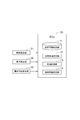
- FIG. 1 is a block diagram showing the configuration of the collision avoidance assistance device according to the first embodiment.
- the collision avoidance assistance device is realized as an ECU 10 (Electronic Control Unit) mounted on a vehicle.
- ECU10 is connected to the object detection part 21 and the vehicle speed detection part 22 via the vehicle-mounted bus etc. which are not shown in figure.
- the object detection unit 21 detects an object around the vehicle, particularly an object in front of the vehicle.
- a millimeter wave radar sensor or the like is used as the object detection unit 21 .
- the object detection unit 21 detects an object by transmitting a radio wave to the periphery of the vehicle and receiving a radio wave reflected from the surrounding object. Thereby, a relative distance from the vehicle, a relative speed with respect to the vehicle, and the like are detected for surrounding objects.
- a camera sensor that captures surrounding objects as an image may be used.
- the vehicle speed detection unit 22 detects the speed of the vehicle.
- a wheel speed sensor or the like is used as the vehicle speed detection unit 22.
- the ECU 10 includes a setting information storage unit 11, a support area setting unit 12, a support control unit 13, and a collision avoidance support unit 14.
- the ECU 10 includes a CPU, a ROM, a RAM, and the like (not shown), and the CPU stores and executes a program stored in the ROM or the like on the RAM, so that the setting information storage unit 11, the support area setting The functions of the unit 12, the support control unit 13, and the collision avoidance support unit 14 are realized.
- the setting information storage unit 11, the support area setting unit 12, the support control unit 13, and the collision avoidance support unit 14 may be realized by a combination with another computer, an electric circuit, or the like instead of the ECU 10 alone.
- the setting information storage unit 11 stores setting information used for setting the support area.
- the support area is set as an area that supports collision avoidance.
- the setting information includes a set lateral acceleration Gyd, a relaxation curve portion passage time T, and a lateral interval W.
- a method for setting the set lateral acceleration Gyd will be described with reference to FIGS.
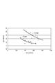
- FIG. 2 is a diagram showing the relationship between the vehicle speed Vs and the lateral acceleration Gy during normal turning.
- FIG. 2 shows approximate curves Cmax and Cmin indicating the maximum value and the minimum value for each vehicle speed Vs with respect to the lateral acceleration Gy observed in the running test on curved roads having various curvature radii. This means that the driver performs steering so as not to exceed the maximum value of the lateral acceleration Gy (maximum lateral acceleration) during normal turning.
- the lateral acceleration Gy depends on the vehicle speed Vs at the time of turning, and decreases as the vehicle speed Vs increases.
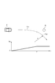
- FIG. 3 is a diagram showing the relationship between the traveling locus of the vehicle C and the lateral acceleration Gy when a collision is avoided by normal steering.
- the traveling locus of the vehicle C when the collision with the obstacle O is avoided by normal steering, the traveling locus of the vehicle C includes a relaxation curve portion Tr1 that is a smooth locus.
- the relaxation curve portion Tr1 when avoiding a collision at a constant steering speed and vehicle speed Vs, the relaxation curve portion Tr1 is a clothoid curve portion represented by a clothoid curve.
- the traveling locus of the vehicle C includes a curved portion Tr2 (an arc portion having a radius of curvature R) following the relaxation curve portion Tr1.
- the lateral acceleration Gy acts on the vehicle C from the start of travel of the relaxation curve portion Tr1, and the maximum value of the lateral acceleration Gy acts at the end of travel of the relaxation curve portion Tr1, that is, at the start of travel of the curved portion Tr2.
- the maximum value of the lateral acceleration Gy acts continuously.
- the set lateral acceleration Gyd is set so as to define the maximum value of the lateral acceleration Gy acting on the vehicle C when the travel of the relaxation curve portion Tr1 ends.
- the set lateral acceleration Gyd is set according to the vehicle speed Vs during steering based on the maximum value (maximum lateral acceleration) of the lateral acceleration Gy during normal turning, that is, the relationship shown in FIG.
- the setting information storage unit 11 stores, for example, a data map indicating the relationship shown in FIG.
- the relaxation curve portion passing time T is set in advance as the time required for traveling of the relaxation curve portion, particularly the clothoid curve portion.
- the relaxation curve portion passing time T corresponds to a steering continuation time (a steering wheel increasing time) until the lateral acceleration Gy reaches the set lateral acceleration Gyd from 0.0 G.
- the relaxation curve passage time T is set to 2.0 to 4.0 seconds, for example, 3.0 seconds as a provisional value in consideration of the road alignment design criteria and the result of the steering sensory evaluation.
- the relaxation curve portion passing time T may be adapted to an appropriate value in consideration of the impact due to the lateral acceleration Gy, the steering speed, the responsiveness of the lateral acceleration Gy to steering, and the like.
- the lateral interval W is set in advance as a lateral distance in the vehicle width direction, which is a distance obtained by adding a marginal distance w to 1/2 of the vehicle width B.
- the marginal distance w is a separation distance secured between the side surface of the vehicle and the obstacle.
- the marginal distance w is set to 0.2 m to 1.0 m, for example, 0.5 m as a provisional value in consideration of the minimum value of the approaching distance at which the driver feels the danger of collision.
- the marginal distance w may be adapted to an appropriate value in consideration of the vehicle speed Vs or the condition of the travel path.
- the support area setting unit 12 sets a support area around the vehicle, particularly in front of the vehicle, based on the set lateral acceleration Gyd determined according to the vehicle speed Vs during steering.
- the support area is set as an area where a collision cannot be easily avoided by normal steering, that is, an area where a collision cannot be easily avoided unless steering exceeding the maximum lateral acceleration is performed.
- the assistance area is also understood as an area where no obstacle can exist in the area as long as collision is avoided by normal steering. Therefore, a situation where an obstacle exists in the assistance area means a situation where there is a high need for assistance in avoiding a collision.
- the support area setting unit 12 acquires vehicle speed information and setting information from the vehicle speed detection unit 22 and the setting information storage unit 11, and sets a support area based on these information.
- the support area setting unit 12 sets the support area when the vehicle turns by steering, that is, when the vehicle starts to travel along the relaxation curve section, or immediately before that.
- the support area of the present embodiment is set as a constant area while traveling on a curved road or a relaxation curve portion.
- FIG. 4 is a diagram illustrating an example of setting a support area.
- the support area A is set as a tapered or bullet-shaped area extending from the front surface of the vehicle C in the traveling direction.
- the boundary between the support area A and the non-support area is an x axis (relative distance) in the traveling direction from the front center of the vehicle C and a y axis (lateral position) in the vehicle width direction from the front center of the vehicle C
- the following equation ( 1L) and (1R) as defined by an approximate expression of a clothoid curve.
- Formula (1L) and Formula (1R) respectively define the boundary in the negative region of the y-axis (the left front of the vehicle C in the example shown in FIG. 4) and the positive region (also the right front of the vehicle C).
- the support area A is set as an area sandwiched between the trajectory at the time of turning left and the trajectory at the time of turning right, and is set in particular as an area (hatching area in FIG. 4) sandwiched between the expressions (1L) and (1R).
- R is the radius of curvature of the curved portion that follows the relaxation curve portion
- L is the section length of the relaxation curve portion
- W is the lateral interval.
- the support control unit 13 permits the collision avoidance support for avoiding the collision. Based on the detection result of the object detection unit 21, the support control unit 13 determines whether the object detected by the object detection unit 21 is an obstacle. When an obstacle is detected, the support control unit 13 performs support based on a comparison between the support area A set by the support area setting unit 12 and the position of the obstacle detected by the object detection unit 21. It is determined whether or not to do.
- the assistance control unit 13 permits collision avoidance assistance when an obstacle is detected in the assistance area A, but does not permit collision avoidance assistance when the obstacle is not detected.
- the collision avoidance support unit 14 performs collision avoidance support for avoiding a collision.
- the collision avoidance support unit 14 performs support when collision avoidance support is permitted, and does not perform support when permission is not permitted.
- collision avoidance assistance is permitted, the collision avoidance assistance unit 14 performs collision avoidance assistance by warning notification, steering intervention, braking intervention, operation of a safety device, and the like.
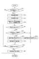
- FIG. 5 is a flowchart showing the operation of the collision avoidance assistance device according to the first embodiment.
- the ECU 10 repeatedly executes the process shown in FIG. 5 at a predetermined cycle.
- the support area setting unit 12 determines whether or not the vehicle C turns by steering, that is, whether or not to start traveling of the relaxation curve unit (step S11).
- the start of travel of the relaxation curve portion Tr1 may be determined based on, for example, the change state of the steering angle, or may be predicted based on the detection state of the object by the object detection unit 21.
- the support area setting unit 12 acquires vehicle speed information from the vehicle speed detection unit 22 (S12). Next, the support area setting unit 12 acquires setting information from the setting information storage unit 11, that is, the set lateral acceleration Gyd, the relaxation curve portion passing time T, and the lateral interval W determined according to the vehicle speed Vs during steering. (S13). Then, the assistance area setting unit 12 substitutes the setting information into the equations (2L) and (2R), and sets the assistance area ahead of the vehicle based on the set lateral acceleration Gyd determined according to the vehicle speed Vs during steering. (S14).
- the support control unit 13 starts the collision avoidance support control.
- the support control unit 13 determines whether an obstacle is detected by the object detection unit 21 (S15). If it is determined in S15 that an obstacle has been detected, the support control unit 13 further determines whether an obstacle has been detected in the support area (S16).
- the support control unit 13 When it is determined that an obstacle is detected in the support area, the support control unit 13 permits the collision avoidance support (S17), and the collision avoidance support unit 14 executes the collision avoidance support (S18). . On the other hand, if it is not determined that an obstacle has been detected in the support area, the support control unit 13 does not permit support for collision avoidance (S19).
- the support area setting unit 12 determines whether or not the vehicle has finished traveling on the curved road, that is, the curved part or the relaxation curve part (S20). The end of traveling of the curved portion or the relaxation curve portion is also determined by the same method as that for starting the traveling of the relaxation curve portion. When it is determined in S20 that the traveling of the curved portion or the relaxation curve portion is finished, the support area setting unit 12 stops the setting of the support area (S21). The collision avoidance assistance device repeatedly executes the processes of steps S15 to S19 until it is determined in step S20 that the running of the curved portion or the relaxation curve portion is finished.
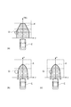
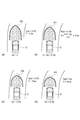
- FIG. 6 is a diagram showing the operation of the collision avoidance support device in comparison with the prior art.
- the support area A ′ is set in front of the vehicle C based on a predicted time TTC (Time To Collision) until the collision according to the vehicle speed Vs. Therefore, even when a collision can be easily avoided by normal steering, if the obstacle O is detected in the support area A ′, the support may be executed. In this case, the occupant of the vehicle C feels uncomfortable in performing the support or feels complicated performing the support.
- TTC Time To Collision
- the assistance area A is set in front of the vehicle C based on the setting information described above.
- the support area A is set as an area where a collision cannot be easily avoided by normal steering.
- the collision avoidance support is permitted, and therefore the collision avoidance support is executed only in a situation where the collision cannot be easily avoided by normal steering.
- FIG. 6B since the obstacle O is not detected in the support area A, the collision avoidance support is not executed. This is because in the state shown in FIG. 6B, collision with the obstacle O can be easily avoided by normal steering.
- FIG. 6C since the obstacle O is detected in the support area A when the vehicle further approaches the obstacle O, collision avoidance assistance is executed. This is because in the state shown in FIG. 6C, collision with the obstacle O cannot be easily avoided by normal steering.
- a collision can be easily performed by normal steering based on the set lateral acceleration Gyd determined according to the vehicle speed Vs during steering.
- An area that cannot be avoided can be set as a support area.
- the collision avoidance assistance can be executed only in a situation where the collision cannot be easily avoided by normal steering by allowing the collision avoidance assistance. Therefore, in a situation where a collision can be easily avoided by normal steering, execution of inappropriate support is suppressed. For this reason, it can suppress that the passenger
- the support area may be set based on a time T until the lateral acceleration Gy of the vehicle reaches the set lateral acceleration Gyd. As a result, it is possible to set an appropriate support area reflecting the steering characteristics.
- the support area may be set based on the side interval W set in the vehicle width direction. As a result, it is possible to set an appropriate support area that secures the lateral interval W in the vehicle width direction.
- the support area may be set based on the turning trajectory of the vehicle. Thereby, an appropriate support area can be set based on the turning trajectory of the vehicle.
- the support area may be set based on an approximate expression of a clothoid curve.
- the support area includes a distance from the front center of the vehicle in the vehicle width direction y, a set lateral acceleration Gyd, a distance from the front center of the vehicle in the traveling direction x, and a time until the vehicle's lateral acceleration reaches the set lateral acceleration.
- May be set based on the equation y Gyd ⁇ x 3 / (6T ⁇ Vs 3 ) ⁇ W, where T is the vehicle speed, Vs is the vehicle speed, and W is the lateral interval.
- the collision avoidance assistance device updates the setting of the assistance area according to the lateral acceleration that changes during the turning of the vehicle.
- FIG. 7 is a block diagram showing the configuration of the collision avoidance assistance device according to the second embodiment.
- the ECU 10 is connected to the lateral acceleration detection unit 23 together with the object detection unit 21 and the vehicle speed detection unit 22.
- the lateral acceleration detector 23 detects the lateral acceleration of the vehicle.
- An acceleration sensor or the like is used as the lateral acceleration detection unit 23.
- the ECU 10 includes a setting information storage unit 11, a support area setting unit 31, a support control unit 13, and a collision avoidance support unit 14.
- the functions of the setting information storage unit 11, the support control unit 13, and the collision avoidance support unit 14 are as follows. This is the same as in the first embodiment.
- the support area setting unit 31 sets the support area in front of the vehicle based on the set lateral acceleration Gyd determined according to the vehicle speed Vs during steering, and sets the support area according to the lateral acceleration Gy that changes during the turn. Update.
- the assistance area setting unit 12 sets an assistance area when the vehicle turns by steering, that is, immediately before or when the vehicle starts traveling on the relaxation curve portion, and the lateral acceleration while the vehicle is traveling on the relaxation curve portion and the bending portion. Based on the lateral acceleration information acquired from the detection unit 23, the setting of the support area is updated. That is, the support area of the present embodiment is set as a variable area during traveling on the relaxation curve portion and the bending portion.
- FIG. 8 is a diagram showing an example of updating the support area A according to the lateral acceleration Gy that changes during turning.
- the set lateral acceleration Gyd 0.3 G
- the relaxation curve section passage time T 3.0 seconds
- the lateral interval W 1.2 m.
- the setting of the support area A is performed as shown in FIG. 8B until the vehicle C is traveling along the relaxation curve portion, that is, until the lateral acceleration Gy acting on the vehicle C reaches 0.0G to 0.3G. It is updated according to the lateral acceleration Gy that changes during turning.
- the relaxation curve section passage time T (0.3 ⁇ Gy) /0.3 ⁇ (3.0 ⁇ Tmin) + Tmin seconds.
- Tmin is given as Tmin ⁇ 0.3 seconds in the update example shown in FIG. 8, for example, so that the support area A equivalent to that in the case of steady circle turning is set.
- the setting of the support area A is updated so that the lateral acceleration Gy acting on the vehicle C increases as the vehicle C travels on the relaxation curve portion and the curved portion, and narrows toward the vehicle C side.
- the setting of the assistance area is updated according to the lateral acceleration Gy that changes during the turning of the vehicle, so that An optimum support area can be set according to the changing lateral acceleration Gy.
- the setting of the support area may be updated so as to narrow toward the vehicle as the lateral acceleration Gy of the vehicle increases.
- the embodiment described above describes the best embodiment of the collision avoidance support device according to the present invention, and the collision avoidance support device according to the present invention is limited to the one described in the present embodiment. is not.
- the collision avoidance assistance device according to the present invention may be a modification of the collision avoidance assistance device according to the present embodiment or application to other devices without departing from the gist of the invention described in each claim. .
- the present invention can be similarly applied to a program for appropriately executing collision avoidance support or a computer-readable recording medium storing the program according to the above-described method.
Landscapes
- Engineering & Computer Science (AREA)
- Transportation (AREA)
- Mechanical Engineering (AREA)
- Automation & Control Theory (AREA)
- Physics & Mathematics (AREA)
- General Physics & Mathematics (AREA)
- Chemical & Material Sciences (AREA)
- Combustion & Propulsion (AREA)
- Traffic Control Systems (AREA)
- Steering Control In Accordance With Driving Conditions (AREA)
- Control Of Driving Devices And Active Controlling Of Vehicle (AREA)
Abstract
Description
y=-{x3/(6R・L)-W} … (1R)
y=-{Gyd・x3/(6T・Vs3)-W} … (2R)
Claims (8)
- 操舵の際の車速に応じて定められる設定横加速度に基づいて、車両の周辺に支援領域を設定する支援領域設定部と、
前記支援領域内に障害物が検出された場合、前記車両の衝突回避の支援を許可する支援制御部と、
を備える衝突回避支援装置。 - 前記支援領域設定部は、さらに前記車両の横加速度が前記設定横加速度に達するまでの時間に基づいて前記支援領域を設定する、請求項1に記載の衝突回避支援装置。
- 前記支援領域設定部は、さらに車幅方向に設定される側方間隔に基づいて前記支援領域を設定する、請求項1または2に記載の衝突回避支援装置。
- 前記支援領域設定部は、前記車両の旋回軌跡に基づいて前記支援領域を設定する、請求項1~3のいずれか一項に記載の衝突回避支援装置。
- 前記支援領域設定部は、クロソイド曲線の近似式に基づいて前記支援領域を設定する、請求項4に記載の衝突回避支援装置。
- 前記支援領域設定部は、
前記車両の前面中央から車幅方向の距離をy、前記設定横加速度をGyd、前記車両の前面中央から進行方向の距離をx、前記車両の横加速度が前記設定横加速度に達するまでの時間をT、前記車速をVs、前記側方間隔をWとした場合、
y=Gyd・x3/(6T・Vs3)-W
の式に基づいて前記支援領域を設定する、請求項5に記載の衝突回避支援装置。 - 前記支援領域設定部は、前記車両の旋回中に変化する横加速度に応じて前記支援領域の設定を更新する、請求項1~6のいずれか一項に記載の衝突回避支援装置。
- 前記支援領域設定部は、前記車両の横加速度が大きくなるほど前記車両の側に狭まるように前記支援領域の設定を更新する、請求項7に記載の衝突回避支援装置
Priority Applications (5)
| Application Number | Priority Date | Filing Date | Title |
|---|---|---|---|
| US14/386,203 US9604640B2 (en) | 2012-03-19 | 2012-03-19 | Collision avoidance assistance device |
| CN201280072434.1A CN104246849B (zh) | 2012-03-19 | 2012-03-19 | 防撞辅助装置 |
| JP2014505844A JP5935875B2 (ja) | 2012-03-19 | 2012-03-19 | 衝突回避支援装置 |
| EP12872152.9A EP2830031A4 (en) | 2012-03-19 | 2012-03-19 | DEVICE FOR SUPPORTING COLLISION PREVENTION |
| PCT/JP2012/057054 WO2013140513A1 (ja) | 2012-03-19 | 2012-03-19 | 衝突回避支援装置 |
Applications Claiming Priority (1)
| Application Number | Priority Date | Filing Date | Title |
|---|---|---|---|
| PCT/JP2012/057054 WO2013140513A1 (ja) | 2012-03-19 | 2012-03-19 | 衝突回避支援装置 |
Publications (1)
| Publication Number | Publication Date |
|---|---|
| WO2013140513A1 true WO2013140513A1 (ja) | 2013-09-26 |
Family
ID=49222007
Family Applications (1)
| Application Number | Title | Priority Date | Filing Date |
|---|---|---|---|
| PCT/JP2012/057054 Ceased WO2013140513A1 (ja) | 2012-03-19 | 2012-03-19 | 衝突回避支援装置 |
Country Status (5)
| Country | Link |
|---|---|
| US (1) | US9604640B2 (ja) |
| EP (1) | EP2830031A4 (ja) |
| JP (1) | JP5935875B2 (ja) |
| CN (1) | CN104246849B (ja) |
| WO (1) | WO2013140513A1 (ja) |
Cited By (2)
| Publication number | Priority date | Publication date | Assignee | Title |
|---|---|---|---|---|
| JP2019148856A (ja) * | 2018-02-26 | 2019-09-05 | 本田技研工業株式会社 | 車両制御装置 |
| JP2023165550A (ja) * | 2022-05-06 | 2023-11-16 | 京セラ株式会社 | 情報処理装置 |
Families Citing this family (19)
| Publication number | Priority date | Publication date | Assignee | Title |
|---|---|---|---|---|
| US9139202B2 (en) * | 2014-01-21 | 2015-09-22 | Elwha Llc | Vehicle collision management responsive to adverse circumstances in an avoidance path |
| US9199642B2 (en) | 2014-01-21 | 2015-12-01 | Elwha Llc | Vehicle collision management responsive to traction conditions in an avoidance path |
| US10309792B2 (en) | 2016-06-14 | 2019-06-04 | nuTonomy Inc. | Route planning for an autonomous vehicle |
| US11092446B2 (en) | 2016-06-14 | 2021-08-17 | Motional Ad Llc | Route planning for an autonomous vehicle |
| US10126136B2 (en) | 2016-06-14 | 2018-11-13 | nuTonomy Inc. | Route planning for an autonomous vehicle |
| US20180001893A1 (en) * | 2016-06-30 | 2018-01-04 | Delphi Technologies, Inc. | Automated vehicle acceleration management system |
| US10857994B2 (en) | 2016-10-20 | 2020-12-08 | Motional Ad Llc | Identifying a stopping place for an autonomous vehicle |
| US10331129B2 (en) | 2016-10-20 | 2019-06-25 | nuTonomy Inc. | Identifying a stopping place for an autonomous vehicle |
| US10681513B2 (en) | 2016-10-20 | 2020-06-09 | nuTonomy Inc. | Identifying a stopping place for an autonomous vehicle |
| US10473470B2 (en) | 2016-10-20 | 2019-11-12 | nuTonomy Inc. | Identifying a stopping place for an autonomous vehicle |
| JP6574407B2 (ja) * | 2016-11-17 | 2019-09-11 | 株式会社デンソー | 車両制御装置、及び車両制御方法 |
| US10379538B1 (en) * | 2017-03-20 | 2019-08-13 | Zoox, Inc. | Trajectory generation using motion primitives |
| US11008039B2 (en) * | 2017-04-12 | 2021-05-18 | Toyota Jidosha Kabushiki Kaisha | Lane change assist apparatus for vehicle |
| MY188554A (en) * | 2017-08-24 | 2021-12-22 | Nissan Motor | Method and device for controlling travel of drive-assisted vehicle |
| US10509410B2 (en) * | 2017-12-06 | 2019-12-17 | Zoox, Inc. | External control of an autonomous vehicle |
| FR3085782B1 (fr) * | 2018-09-11 | 2020-11-27 | Transdev Group | Procede et dispositif d'identification d'obstacles sur un trajet de vehicule automobile |
| EP3886076B1 (en) * | 2020-03-27 | 2025-09-10 | Aptiv Technologies AG | Warning system for a host automotive vehicle |
| JP7468409B2 (ja) | 2021-03-01 | 2024-04-16 | トヨタ自動車株式会社 | 車両衝突回避支援装置 |
| DE102022210507A1 (de) * | 2022-10-05 | 2024-04-11 | Continental Automotive Technologies GmbH | Alarmsystem zur Warnung vulnerabler Verkehrsteilnehmer in einem vorgegebenen Straßenabschnitt |
Citations (5)
| Publication number | Priority date | Publication date | Assignee | Title |
|---|---|---|---|---|
| JP2002211428A (ja) * | 2001-01-18 | 2002-07-31 | Nissan Motor Co Ltd | 車線追従制御装置 |
| JP2009012493A (ja) * | 2007-06-29 | 2009-01-22 | Hitachi Ltd | 車両運転補助装置 |
| JP2009199583A (ja) * | 2008-01-22 | 2009-09-03 | Advanced Telecommunication Research Institute International | 危険運転予防意識判定システムおよび危険運転予防意識判定方法 |
| JP2010173511A (ja) * | 2009-01-30 | 2010-08-12 | Nissan Motor Co Ltd | 車両用運転支援装置および車両用運転支援方法 |
| JP2011210102A (ja) | 2010-03-30 | 2011-10-20 | Mazda Motor Corp | 車両用運転支援装置 |
Family Cites Families (14)
| Publication number | Priority date | Publication date | Assignee | Title |
|---|---|---|---|---|
| JPH05203737A (ja) * | 1992-01-29 | 1993-08-10 | Mazda Motor Corp | 車両の障害物検出装置 |
| JP2799375B2 (ja) * | 1993-09-30 | 1998-09-17 | 本田技研工業株式会社 | 衝突防止装置 |
| US8364366B2 (en) * | 2005-06-24 | 2013-01-29 | Deere & Company | System and method for providing a safety zone associated with a vehicle |
| JP2007137126A (ja) * | 2005-11-15 | 2007-06-07 | Mazda Motor Corp | 車両の障害物検知装置 |
| JP5130638B2 (ja) * | 2006-03-22 | 2013-01-30 | 日産自動車株式会社 | 回避操作算出装置、回避制御装置、各装置を備える車両、回避操作算出方法および回避制御方法 |
| DE102006042666A1 (de) * | 2006-09-12 | 2008-03-27 | Robert Bosch Gmbh | Verfahren zur Vermeidung bzw. Folgenminderung der Kollision eines Fahrzeugs mit mindestens einem Objekt |
| JP2009124930A (ja) * | 2007-11-12 | 2009-06-04 | Shizuo Shirata | 永久モーター |
| DE102008016377A1 (de) * | 2008-03-29 | 2009-10-01 | Daimler Ag | Verfahren zum Betrieb eines Kraftfahrzeuges |
| JP5174609B2 (ja) * | 2008-10-10 | 2013-04-03 | 日立オートモティブシステムズ株式会社 | 走行支援装置 |
| JP5347499B2 (ja) * | 2008-12-27 | 2013-11-20 | 日産自動車株式会社 | 車両制御装置及び車両制御方法 |
| DE102009012226A1 (de) * | 2009-03-07 | 2010-09-09 | Daimler Ag | Verfahren zur Vermeidung oder Folgenminderung einer Kollision eines Fahrzeugs mit einem Hindernis |
| DE102009020649A1 (de) | 2009-05-08 | 2010-11-18 | Daimler Ag | Verfahren und Vorrichtung zur Kollisionsvermeidung für ein Fahrzeug durch Ausweichen vor einem Hindernis |
| JP5248451B2 (ja) | 2009-09-04 | 2013-07-31 | 本田技研工業株式会社 | 車両用接触回避支援装置 |
| EP2763119B1 (en) * | 2011-09-26 | 2019-04-03 | Toyota Jidosha Kabushiki Kaisha | Vehicle driving assistance system |
-
2012
- 2012-03-19 EP EP12872152.9A patent/EP2830031A4/en not_active Ceased
- 2012-03-19 CN CN201280072434.1A patent/CN104246849B/zh not_active Expired - Fee Related
- 2012-03-19 US US14/386,203 patent/US9604640B2/en not_active Expired - Fee Related
- 2012-03-19 JP JP2014505844A patent/JP5935875B2/ja not_active Expired - Fee Related
- 2012-03-19 WO PCT/JP2012/057054 patent/WO2013140513A1/ja not_active Ceased
Patent Citations (5)
| Publication number | Priority date | Publication date | Assignee | Title |
|---|---|---|---|---|
| JP2002211428A (ja) * | 2001-01-18 | 2002-07-31 | Nissan Motor Co Ltd | 車線追従制御装置 |
| JP2009012493A (ja) * | 2007-06-29 | 2009-01-22 | Hitachi Ltd | 車両運転補助装置 |
| JP2009199583A (ja) * | 2008-01-22 | 2009-09-03 | Advanced Telecommunication Research Institute International | 危険運転予防意識判定システムおよび危険運転予防意識判定方法 |
| JP2010173511A (ja) * | 2009-01-30 | 2010-08-12 | Nissan Motor Co Ltd | 車両用運転支援装置および車両用運転支援方法 |
| JP2011210102A (ja) | 2010-03-30 | 2011-10-20 | Mazda Motor Corp | 車両用運転支援装置 |
Non-Patent Citations (1)
| Title |
|---|
| See also references of EP2830031A4 |
Cited By (3)
| Publication number | Priority date | Publication date | Assignee | Title |
|---|---|---|---|---|
| JP2019148856A (ja) * | 2018-02-26 | 2019-09-05 | 本田技研工業株式会社 | 車両制御装置 |
| US11054832B2 (en) | 2018-02-26 | 2021-07-06 | Honda Motor Co., Ltd. | Vehicle control device for setting vehicle offset spacing |
| JP2023165550A (ja) * | 2022-05-06 | 2023-11-16 | 京セラ株式会社 | 情報処理装置 |
Also Published As
| Publication number | Publication date |
|---|---|
| US9604640B2 (en) | 2017-03-28 |
| CN104246849A (zh) | 2014-12-24 |
| EP2830031A1 (en) | 2015-01-28 |
| JPWO2013140513A1 (ja) | 2015-08-03 |
| CN104246849B (zh) | 2018-01-02 |
| US20150094943A1 (en) | 2015-04-02 |
| EP2830031A4 (en) | 2016-08-10 |
| JP5935875B2 (ja) | 2016-06-15 |
Similar Documents
| Publication | Publication Date | Title |
|---|---|---|
| JP5935875B2 (ja) | 衝突回避支援装置 | |
| CN113734159B (zh) | 用于车辆的控制设备和车辆的控制方法 | |
| JP6859902B2 (ja) | 車両制御装置 | |
| JP6491596B2 (ja) | 車両制御装置及び車両制御方法 | |
| US11427166B2 (en) | Adaptive AEB system considering steerable path and control method thereof | |
| JP6524943B2 (ja) | 走行支援装置 | |
| JP5804032B2 (ja) | 車両制御装置 | |
| JP6740970B2 (ja) | 走行支援装置 | |
| JP6384495B2 (ja) | 追い越し支援装置 | |
| CN109311476B (zh) | 用于实施至少部分自动化的行驶机动操纵的方法和设备 | |
| JP5900293B2 (ja) | 衝突回避支援装置及び衝突回避支援方法 | |
| CN105015546B (zh) | 预防车辆追尾的主动紧急转向系统及方法 | |
| WO2016017494A1 (ja) | 運転支援装置 | |
| JP2018156290A (ja) | 衝突回避装置 | |
| CN111565981B (zh) | 车辆控制装置 | |
| WO2018074541A1 (ja) | 車両制御装置 | |
| JP2016037203A (ja) | 運転支援装置 | |
| US12570277B2 (en) | Lateral movement system for collision avoidance | |
| CN108216209B (zh) | 驾驶支持器 | |
| JP6834633B2 (ja) | 運転支援装置 | |
| JP5915441B2 (ja) | 車両制御装置 | |
| EP4414234B1 (en) | Method and apparatus for collision avoidance or impact force reduction | |
| CN116486638B (zh) | 路径生成装置和路径生成方法 | |
| JP6988717B2 (ja) | 衝突判定装置 | |
| CN117774951A (zh) | 驾驶辅助装置、驾驶辅助方法以及记录介质 |
Legal Events
| Date | Code | Title | Description |
|---|---|---|---|
| 121 | Ep: the epo has been informed by wipo that ep was designated in this application |
Ref document number: 12872152 Country of ref document: EP Kind code of ref document: A1 |
|
| ENP | Entry into the national phase |
Ref document number: 2014505844 Country of ref document: JP Kind code of ref document: A |
|
| NENP | Non-entry into the national phase |
Ref country code: DE |
|
| WWE | Wipo information: entry into national phase |
Ref document number: 2012872152 Country of ref document: EP |
|
| WWE | Wipo information: entry into national phase |
Ref document number: 14386203 Country of ref document: US |