WO2013140548A1 - 過給機付き内燃機関の制御装置 - Google Patents
過給機付き内燃機関の制御装置 Download PDFInfo
- Publication number
- WO2013140548A1 WO2013140548A1 PCT/JP2012/057188 JP2012057188W WO2013140548A1 WO 2013140548 A1 WO2013140548 A1 WO 2013140548A1 JP 2012057188 W JP2012057188 W JP 2012057188W WO 2013140548 A1 WO2013140548 A1 WO 2013140548A1
- Authority
- WO
- WIPO (PCT)
- Prior art keywords
- cylinder
- fuel
- abnormal combustion
- ignition
- fuel supply
- Prior art date
- Legal status (The legal status is an assumption and is not a legal conclusion. Google has not performed a legal analysis and makes no representation as to the accuracy of the status listed.)
- Ceased
Links
Images


Classifications
-
- F—MECHANICAL ENGINEERING; LIGHTING; HEATING; WEAPONS; BLASTING
- F02—COMBUSTION ENGINES; HOT-GAS OR COMBUSTION-PRODUCT ENGINE PLANTS
- F02P—IGNITION, OTHER THAN COMPRESSION IGNITION, FOR INTERNAL-COMBUSTION ENGINES; TESTING OF IGNITION TIMING IN COMPRESSION-IGNITION ENGINES
- F02P5/00—Advancing or retarding ignition; Control therefor
- F02P5/04—Advancing or retarding ignition; Control therefor automatically, as a function of the working conditions of the engine or vehicle or of the atmospheric conditions
- F02P5/045—Advancing or retarding ignition; Control therefor automatically, as a function of the working conditions of the engine or vehicle or of the atmospheric conditions combined with electronic control of other engine functions, e.g. fuel injection
-
- F—MECHANICAL ENGINEERING; LIGHTING; HEATING; WEAPONS; BLASTING
- F02—COMBUSTION ENGINES; HOT-GAS OR COMBUSTION-PRODUCT ENGINE PLANTS
- F02D—CONTROLLING COMBUSTION ENGINES
- F02D41/00—Electrical control of supply of combustible mixture or its constituents
- F02D41/008—Controlling each cylinder individually
- F02D41/0087—Selective cylinder activation, i.e. partial cylinder operation
-
- F—MECHANICAL ENGINEERING; LIGHTING; HEATING; WEAPONS; BLASTING
- F02—COMBUSTION ENGINES; HOT-GAS OR COMBUSTION-PRODUCT ENGINE PLANTS
- F02D—CONTROLLING COMBUSTION ENGINES
- F02D41/00—Electrical control of supply of combustible mixture or its constituents
- F02D41/0002—Controlling intake air
- F02D41/0007—Controlling intake air for control of turbo-charged or super-charged engines
-
- F—MECHANICAL ENGINEERING; LIGHTING; HEATING; WEAPONS; BLASTING
- F02—COMBUSTION ENGINES; HOT-GAS OR COMBUSTION-PRODUCT ENGINE PLANTS
- F02D—CONTROLLING COMBUSTION ENGINES
- F02D41/00—Electrical control of supply of combustible mixture or its constituents
- F02D41/22—Safety or indicating devices for abnormal conditions
-
- F—MECHANICAL ENGINEERING; LIGHTING; HEATING; WEAPONS; BLASTING
- F02—COMBUSTION ENGINES; HOT-GAS OR COMBUSTION-PRODUCT ENGINE PLANTS
- F02P—IGNITION, OTHER THAN COMPRESSION IGNITION, FOR INTERNAL-COMBUSTION ENGINES; TESTING OF IGNITION TIMING IN COMPRESSION-IGNITION ENGINES
- F02P5/00—Advancing or retarding ignition; Control therefor
- F02P5/04—Advancing or retarding ignition; Control therefor automatically, as a function of the working conditions of the engine or vehicle or of the atmospheric conditions
- F02P5/145—Advancing or retarding ignition; Control therefor automatically, as a function of the working conditions of the engine or vehicle or of the atmospheric conditions using electrical means
- F02P5/15—Digital data processing
- F02P5/1502—Digital data processing using one central computing unit
- F02P5/1516—Digital data processing using one central computing unit with means relating to exhaust gas recirculation, e.g. turbo
-
- F—MECHANICAL ENGINEERING; LIGHTING; HEATING; WEAPONS; BLASTING
- F02—COMBUSTION ENGINES; HOT-GAS OR COMBUSTION-PRODUCT ENGINE PLANTS
- F02P—IGNITION, OTHER THAN COMPRESSION IGNITION, FOR INTERNAL-COMBUSTION ENGINES; TESTING OF IGNITION TIMING IN COMPRESSION-IGNITION ENGINES
- F02P5/00—Advancing or retarding ignition; Control therefor
- F02P5/04—Advancing or retarding ignition; Control therefor automatically, as a function of the working conditions of the engine or vehicle or of the atmospheric conditions
- F02P5/145—Advancing or retarding ignition; Control therefor automatically, as a function of the working conditions of the engine or vehicle or of the atmospheric conditions using electrical means
- F02P5/15—Digital data processing
- F02P5/152—Digital data processing dependent on pinking
- F02P5/1528—Digital data processing dependent on pinking for turbocompressed engine
-
- F—MECHANICAL ENGINEERING; LIGHTING; HEATING; WEAPONS; BLASTING
- F02—COMBUSTION ENGINES; HOT-GAS OR COMBUSTION-PRODUCT ENGINE PLANTS
- F02D—CONTROLLING COMBUSTION ENGINES
- F02D35/00—Controlling engines, dependent on conditions exterior or interior to engines, not otherwise provided for
- F02D35/02—Controlling engines, dependent on conditions exterior or interior to engines, not otherwise provided for on interior conditions
- F02D35/023—Controlling engines, dependent on conditions exterior or interior to engines, not otherwise provided for on interior conditions by determining the cylinder pressure
-
- F—MECHANICAL ENGINEERING; LIGHTING; HEATING; WEAPONS; BLASTING
- F02—COMBUSTION ENGINES; HOT-GAS OR COMBUSTION-PRODUCT ENGINE PLANTS
- F02D—CONTROLLING COMBUSTION ENGINES
- F02D41/00—Electrical control of supply of combustible mixture or its constituents
- F02D41/008—Controlling each cylinder individually
-
- F—MECHANICAL ENGINEERING; LIGHTING; HEATING; WEAPONS; BLASTING
- F02—COMBUSTION ENGINES; HOT-GAS OR COMBUSTION-PRODUCT ENGINE PLANTS
- F02D—CONTROLLING COMBUSTION ENGINES
- F02D41/00—Electrical control of supply of combustible mixture or its constituents
- F02D41/30—Controlling fuel injection
- F02D41/32—Controlling fuel injection of the low pressure type
- F02D41/34—Controlling fuel injection of the low pressure type with means for controlling injection timing or duration
-
- F—MECHANICAL ENGINEERING; LIGHTING; HEATING; WEAPONS; BLASTING
- F02—COMBUSTION ENGINES; HOT-GAS OR COMBUSTION-PRODUCT ENGINE PLANTS
- F02P—IGNITION, OTHER THAN COMPRESSION IGNITION, FOR INTERNAL-COMBUSTION ENGINES; TESTING OF IGNITION TIMING IN COMPRESSION-IGNITION ENGINES
- F02P5/00—Advancing or retarding ignition; Control therefor
- F02P5/04—Advancing or retarding ignition; Control therefor automatically, as a function of the working conditions of the engine or vehicle or of the atmospheric conditions
- F02P5/145—Advancing or retarding ignition; Control therefor automatically, as a function of the working conditions of the engine or vehicle or of the atmospheric conditions using electrical means
- F02P5/15—Digital data processing
- F02P5/1502—Digital data processing using one central computing unit
- F02P5/1512—Digital data processing using one central computing unit with particular means concerning an individual cylinder
-
- Y—GENERAL TAGGING OF NEW TECHNOLOGICAL DEVELOPMENTS; GENERAL TAGGING OF CROSS-SECTIONAL TECHNOLOGIES SPANNING OVER SEVERAL SECTIONS OF THE IPC; TECHNICAL SUBJECTS COVERED BY FORMER USPC CROSS-REFERENCE ART COLLECTIONS [XRACs] AND DIGESTS
- Y02—TECHNOLOGIES OR APPLICATIONS FOR MITIGATION OR ADAPTATION AGAINST CLIMATE CHANGE
- Y02T—CLIMATE CHANGE MITIGATION TECHNOLOGIES RELATED TO TRANSPORTATION
- Y02T10/00—Road transport of goods or passengers
- Y02T10/10—Internal combustion engine [ICE] based vehicles
- Y02T10/12—Improving ICE efficiencies
-
- Y—GENERAL TAGGING OF NEW TECHNOLOGICAL DEVELOPMENTS; GENERAL TAGGING OF CROSS-SECTIONAL TECHNOLOGIES SPANNING OVER SEVERAL SECTIONS OF THE IPC; TECHNICAL SUBJECTS COVERED BY FORMER USPC CROSS-REFERENCE ART COLLECTIONS [XRACs] AND DIGESTS
- Y02—TECHNOLOGIES OR APPLICATIONS FOR MITIGATION OR ADAPTATION AGAINST CLIMATE CHANGE
- Y02T—CLIMATE CHANGE MITIGATION TECHNOLOGIES RELATED TO TRANSPORTATION
- Y02T10/00—Road transport of goods or passengers
- Y02T10/10—Internal combustion engine [ICE] based vehicles
- Y02T10/40—Engine management systems
Definitions
- This invention relates to a control device for an internal combustion engine with a supercharger.
- the spark plug is a device that ignites an air-fuel mixture by electrically generating sparks in a spark ignition internal combustion engine.
- a high voltage is applied between the center electrode of the spark plug and the ground electrode, the insulation between the electrodes is broken and a discharge phenomenon occurs in which a current flows, and an electric spark is generated.
- the voltage level required to form a spark between the electrodes of the spark plug (hereinafter referred to as ignition required voltage) tends to increase as the air-fuel ratio becomes leaner. Therefore, the ignition request voltage increases during the fuel cut.
- Patent Document 1 discloses that the required ignition voltage is increased during fuel cut, and leakage is likely to occur in the ignition circuit. Further, a control device that maintains the required ignition voltage low by correcting the ignition timing to the advance side under the fuel cut condition has been disclosed. Furthermore, it is disclosed that the correction of the ignition timing to the advance side is performed when the fuel cut condition continues a plurality of times.
- the applicant has recognized the following documents including the above-mentioned documents as related to the present invention.
- abnormal combustion such as a sudden pre-ignition in a supercharging region (for example, a low rotation high load region) (combustion starts earlier than the ignition timing and an excessive in-cylinder pressure is generated. Phenomenon).
- a supercharging region for example, a low rotation high load region
- Phenomenon In order to suppress the continuous occurrence of abnormal combustion in the supercharging region, it is conceivable to execute fuel cut. If the fuel cut is executed as described above, the ignition request voltage increases. Therefore, it is necessary to take measures so that the required ignition voltage does not exceed the withstand voltage of the entire ignition system (ignition plug, plug tube, each connecting portion, etc.). As one countermeasure, it is conceivable to advance the ignition timing as in the control device of Patent Document 1.
- the load based on the in-cylinder charged air amount in the supercharging region is higher than that of a non-supercharged NA (Natural Aspiration) engine. Therefore, the compression pressure is higher than that of the NA engine, and the ignition request voltage is also higher. As a result, higher ignition energy is required. Therefore, further improvement is desired from the viewpoint of improving fuel efficiency.
- NA Natural Aspiration
- An object of the present invention is to provide a control device for an internal combustion engine with a supercharger capable of improving fuel consumption.
- a first invention is a control device for an internal combustion engine with a supercharger comprising a fuel supply means for supplying fuel into each cylinder and a spark plug for each cylinder, Ignition timing setting means for setting a basic ignition timing for generating a spark by the spark plug according to the operating state of the internal combustion engine; An abnormal combustion occurrence cylinder detecting means for detecting an abnormal combustion occurrence cylinder in which abnormal combustion has occurred in the supercharging region for each cycle; A fuel cut execution means for executing a fuel cut for stopping the fuel supply by the fuel supply means for the abnormal combustion occurrence cylinder; For the abnormal combustion occurrence cylinder, the ignition timing is changed so that the crank angle width between the compression top dead center and the basic ignition timing is expanded for several cycles after starting the fuel cut, and after the several cycles have elapsed. And a fuel cut execution ignition control means for executing an ignition cut prohibiting the generation of sparks by the spark plug.
- the second invention is the first invention, wherein A fuel supply amount setting means for setting a basic fuel supply amount of the fuel supply means according to an operating state of the internal combustion engine; Fuel supply amount increase correction means for increasing and correcting the basic fuel supply amount for a predetermined cycle for the abnormal combustion occurrence cylinder, The fuel cut executing means executes the fuel cut when abnormal combustion is still occurring in the abnormal combustion generating cylinder after the predetermined cycle has elapsed.
- the third invention is the first or second invention, wherein
- the fuel supply means includes an in-cylinder injector that directly injects fuel into the cylinder, and a port injector that injects fuel into the intake port,
- the fuel cut execution means detects that the predetermined cylinder is an abnormal combustion generation cylinder in the current cycle by the abnormal combustion generation cylinder detection means after the port injector starts fuel injection for the next cycle for the predetermined cylinder. In this case, the fuel injection amount for the next cycle of the in-cylinder injector is corrected to be increased, and the fuel cut is executed from the next cycle of the next cycle.
- the ignition timing is changed so that the crank angle width between the compression top dead center and the basic ignition timing is expanded for several cycles after the fuel cut is started. Therefore, it is possible to ignite with a low in-cylinder pressure. Since the in-cylinder pressure is low, an excessive increase in the ignition request voltage can be suppressed.
- the supercharged engine is particularly effective because the cylinder pressure is higher than that of the NA engine. Moreover, the unburned fuel remaining in the cylinder by ignition can be stably burned.
- an ignition cut that prohibits the generation of sparks by the spark plug is further executed. Therefore, fuel consumption can be improved by reducing power consumption.
- the ignition cut is effective in improving fuel efficiency.
- the fuel cut is performed in order to suppress the continuous occurrence of abnormal combustion in the supercharging region, it is possible to suppress the excessive increase in the ignition request voltage and improve the fuel consumption.
- the basic fuel supply amount is increased and corrected for a predetermined cycle for the abnormal combustion-occurring cylinder. Further, after the predetermined cycle, when the abnormal combustion is still occurring in the abnormal combustion generation cylinder, the fuel cut is executed. Therefore, when the occurrence of abnormal combustion can be suppressed by A / F enrichment, it is not necessary to perform fuel cut. Therefore, abnormal combustion can be suppressed without fear of high voltage leakage.
- the predetermined cylinder is an abnormal combustion generating cylinder in the current cycle after the port injector starts fuel injection for the next cycle for the predetermined cylinder
- the fuel injection amount for the next cycle is corrected to be increased. Therefore, even when the fuel cut cannot be executed immediately, the occurrence of abnormal combustion can be suppressed by A / F enrichment. Further, according to the third invention, fuel cut is executed from the next cycle of the next cycle, and the occurrence of abnormal combustion can be suppressed more reliably.
- Embodiment 1 of this invention It is a conceptual diagram showing the system configuration
- MFB Mass Fraction Burnt
- MFB Mass Fraction Burnt
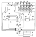
- FIG. 1 is a conceptual diagram showing a system configuration according to the first embodiment of the present invention.
- the system shown in FIG. 1 includes an internal combustion engine (hereinafter, also simply referred to as an engine) 10 in which the exhaust amount is downsized by supercharging.
- the internal combustion engine 10 is mounted on a vehicle or the like and used as a power source.
- the internal combustion engine 10 shown in FIG. 1 is an in-line four-cylinder type, in the present invention, the number of cylinders and the cylinder arrangement are not limited thereto.
- the first to fourth cylinders are denoted as # 1 to # 4, respectively.
- Each cylinder of the internal combustion engine 10 has an in-cylinder injector 12 that directly injects fuel (for example, gasoline, ethanol) into the cylinder (combustion chamber), an ignition plug 13 for igniting the air-fuel mixture, and an in-cylinder pressure.
- An in-cylinder pressure sensor 14 is provided for outputting a signal.
- An intake passage 16 and an exhaust passage 18 are connected to each cylinder of the internal combustion engine 10.
- An intake valve 20 that opens and closes between the cylinder (combustion chamber) and the intake passage 16 is provided at the downstream end of the intake passage 16.
- An exhaust valve 22 that opens and closes between the cylinder (combustion chamber) and the exhaust passage 18 is provided at the upstream end of the exhaust passage 18.
- An air-fuel ratio sensor 23 that outputs a signal corresponding to the exhaust air-fuel ratio is provided in the vicinity of the joining portion of the exhaust passage 18.
- the internal combustion engine 10 includes a turbocharger 24 that performs supercharging with the energy of exhaust gas.
- the turbocharger 24 includes a turbine 24a that is rotated by the energy of the exhaust gas, and a compressor 24b that is rotated by being driven by the turbine 24a.
- the turbine 24 a is disposed in the exhaust passage 18 downstream of the air-fuel ratio sensor 23.
- the compressor 24 b is provided in the middle of the intake passage 16.
- a catalyst 26 for purifying harmful components in the exhaust gas is provided in the exhaust passage 18 downstream of the turbine 24a.
- the catalyst 26 for example, a three-way catalyst is used.
- an air cleaner 28 is provided Near the inlet of the intake passage 16, an air cleaner 28 is provided.
- An air flow meter 30 that outputs a signal corresponding to the flow rate of air taken into the intake passage 16 is provided in the vicinity of the downstream side of the air cleaner 28.
- a compressor 24 b is provided downstream of the air flow meter 30.
- a supercharging pressure sensor 31 that outputs a signal corresponding to the supercharging pressure is provided downstream of the compressor 24b.
- An intercooler 32 is provided downstream of the supercharging pressure sensor 31.
- An electronically controlled throttle valve 34 is provided downstream of the intercooler 32.
- An intake port 36 is provided for each cylinder downstream of the throttle valve 34.
- the fresh air drawn through the air cleaner 28 is compressed by the compressor 24b of the turbocharger 24 and then cooled by the intercooler 32.
- the cooled fresh air passes through the throttle valve 34 and is distributed to each cylinder and flows in.
- the system of this embodiment further includes an ECU (Electronic Control Unit) 50.
- ECU50 is comprised by the arithmetic processing apparatus provided with the memory circuit containing ROM, RAM, etc., for example.
- the air-fuel ratio sensor 23 On the input side of the ECU 50, in addition to the in-cylinder pressure sensor 14, the air-fuel ratio sensor 23, the air flow meter 30, the supercharging pressure sensor 31, the crank angle sensor 52 for detecting the crank angle and the crank angular speed, and the knocking intensity are detected.
- Various sensors for detecting the operation state of the internal combustion engine 10 such as a knock sensor 54 for performing the operation and a water temperature sensor 56 for detecting the temperature of the cooling water for cooling the internal combustion engine 10 are connected.
- Various actuators for controlling the operating state of the internal combustion engine 10 such as the in-cylinder injector 12, the ignition plug 13, and the throttle valve 34 are connected to the output side of the ECU 50.
- the ECU 50 has a function of storing various data that changes according to the crank angle as time series data together with the crank angle.
- the time series data includes various sensor outputs and various indexes, parameters, and the like calculated based on the outputs.
- ECU50 controls the driving
- the crank angle and the engine speed are calculated based on the output of the crank angle sensor 52, and the intake air amount is calculated based on the output of the air flow meter 30.
- the engine load (load factor) is calculated based on the intake air amount, the engine speed, and the like.
- the fuel injection amount is calculated based on the intake air amount, the load, and the like.
- a basic fuel injection amount (basic fuel supply amount) that sets the exhaust air-fuel ratio to the stoichiometric air-fuel ratio (stoichiometric) is set (fuel supply amount setting function).
- the fuel injection timing and the ignition timing for energizing the spark plug 13 are determined based on the crank angle.
- a basic value of the ignition timing a basic ignition timing is set in accordance with an operation region determined by the engine speed and the load (basic ignition timing setting function). When these times arrive, the in-cylinder injector 12 and the spark plug 13 are driven. Thereby, the air-fuel mixture is combusted in the cylinder, and the internal combustion engine 10 can be operated.
- Measures to enrich the air-fuel ratio (hereinafter also simply referred to as A / F) by increasing the fuel can be considered in order to prevent the continuous occurrence of abnormal combustion.
- a / F air-fuel ratio
- the compression end temperature is lowered by the latent heat of vaporization of the fuel.
- F / C fuel cut
- F / C fuel cut
- the fuel cut is executed when the continuous occurrence of abnormal combustion does not stop even in the A / F rich state.
- the fuel cut is executed, no fuel is injected. Therefore, the fuel in the cylinder is only in-cylinder fuel wet or port fuel wet. As a result, an A / F lean state is set.
- the required ignition voltage of the ignition system increases. Therefore, there is a possibility that the required ignition voltage exceeds the withstand voltage of the entire ignition system (ignition plug 13, plug tube, each connecting portion, etc.).
- the withstand voltage of the entire ignition system is exceeded with high probability. In particular, it becomes severe at low revolutions when the boost pressure is high and the in-cylinder temperature is low.
- a misfire may occur after the fuel cut has returned to normal.
- unburned fuel and air may flow into the catalyst 26 due to misfire, resulting in catalyst melting damage at a high temperature due to an oxidation reaction.
- a supercharged engine is difficult to ignite and is not flammable.
- the reason why it is difficult to ignite is that the compression pressure is higher than the NA engine and the ignition required voltage is also higher.
- the compression pressure is higher than the NA engine and the ignition required voltage is also higher.
- it is desired to discharge for a long time but it requires many times as much ignition energy as NA engine. Therefore, improvement in fuel consumption by reducing power consumption is desired.
- this system aims to improve fuel efficiency by reducing power consumption due to ignition cut.
- the merit of fuel efficiency improvement by ignition cut is larger than that of NA engine.
- the control device for an internal combustion engine with a supercharger executes fuel cut for the abnormal combustion generation cylinder in which abnormal combustion has occurred in the supercharging region.
- the ignition timing is changed so that the crank angle width between the compression top dead center and the basic ignition timing is expanded for several cycles after the fuel cut is started. Further, after the above several cycles, the ignition cut is executed while the fuel cut is continued.
- the basic fuel supply amount is increased and corrected for a predetermined cycle for the abnormal combustion-occurring cylinder prior to the fuel cut. If abnormal combustion is still occurring after the predetermined cycle has elapsed, fuel cut is executed.
- abnormal combustion can be suppressed by A / F enrichment, it is not necessary to perform fuel cut. Therefore, abnormal combustion can be suppressed without fear of high voltage leakage.
- the control for changing the ignition timing is a control for retarding the ignition timing.
- the basic fuel supply amount is corrected to be increased, so that the fuel wet amount such as the in-cylinder fuel wet amount and the port fuel wet amount due to blowback is large.
- the crank angle width is expanded to the retard side. The ignition timing is greatly retarded to burn a large amount of residual fuel and reduce the amount of unburned gas.
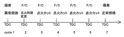
- FIG. 2 is a time chart showing an example of characteristic control in the system of the present embodiment.
- the ECU 50 detects an abnormal combustion generation cylinder in which abnormal combustion has occurred near the compression top dead center (TDC).
- TDC compression top dead center
- the ECU 50 performs fuel cut for the abnormal combustion-occurring cylinder and changes the ignition timing as described above.
- the ECU 50 executes the ignition cut while continuing the fuel cut.
- fuel cut and ignition cut are continued.
- the fuel cut return condition is satisfied, the fuel cut returns to normal, and normal combustion is performed.
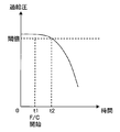
- FIG. 3 is a diagram showing a change in supercharging pressure when the fuel cut is executed.
- the state where the supercharging pressure is higher than the threshold continues until time t2.
- This threshold value corresponds to the withstand voltage of the ignition system.
- the state where the supercharging pressure is higher than the threshold value may continue for several cycles. Since the ignition request voltage is high during these several cycles, the ignition timing is changed as described above in the system of this embodiment. Thereby, high voltage leakage can be suppressed.
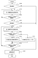
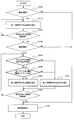
- FIG. 4 is a flowchart of a control routine executed by the ECU 50 in order to realize the above-described operation.
- the ECU 50 determines whether or not abnormal combustion has occurred for each cylinder (step S100). For example, the ECU 50 determines whether or not abnormal combustion such as pre-ignition has occurred based on the relationship between the crank angle at which the in-cylinder pressure sensor 14 or the knock sensor 54 outputs a peak value and the ignition timing. If the peak value is output at a crank angle advanced by a predetermined value or more than during normal combustion, it is determined that abnormal combustion has occurred. Further, when the MFB (Mass Fraction Burnt) 50% point is earlier than the normal combustion by a predetermined value or more, it can be determined that abnormal combustion has occurred. If abnormal combustion has not occurred, normal control is executed (step S190), and the routine is terminated.
- MFB Mass Fraction Burnt
- step S110 the ECU 50 executes first continuous generation prevention control in order to suppress the continuous occurrence of abnormal combustion (step S110).
- the basic fuel injection amount supplied into the cylinder of the abnormal combustion generation cylinder is corrected to be increased.
- the A / F rich state is obtained by the increase correction. For example, the air-fuel ratio is changed from 14.6 (stoichi) to 12. If it is determined that abnormal combustion has occurred in a plurality of cylinders during one cycle, the basic fuel injection amount is corrected to be increased in all cylinders.
- ECU 50 determines whether or not a predetermined cycle or a predetermined time has elapsed after executing the first continuous occurrence prevention control (step S120). If the predetermined cycle or the predetermined time has not yet elapsed, the process returns to step S110.
- the ECU 50 determines whether or not abnormal combustion is still occurring in the abnormal combustion generation cylinder detected in step S100, that is, whether abnormal combustion is continuously occurring. It is determined whether or not (step S130). If abnormal combustion has not occurred, normal control is executed (step S190), and the routine is terminated.
- step S130 when it is determined that abnormal combustion is continuously generated, the ECU 50 determines that the continuous generation of abnormal combustion has not been suppressed by the first continuous generation prevention control. Therefore, the ECU 50 executes the second continuous occurrence prevention control (step S140).
- the second continuous generation prevention control a fuel cut (F / C) for stopping the fuel supply to the abnormal combustion generation cylinder is executed.
- fuel cut is executed in all cylinders.
- ECU50 determines whether it is within several cycles after starting fuel cut (step S150).
- the several cycles may be, for example, a preset time based on experiments or simulations from the start of fuel cut until the supercharging pressure falls below a threshold value (FIG. 3). Further, it may be determined whether or not the supercharging pressure is lower than the threshold value for each cycle, and the determination condition of step S150 may be satisfied when the supercharging pressure is lower than the threshold value.
- the ECU 50 changes the ignition timing of the abnormal combustion-occurring cylinder during the fuel cut (step S160). Specifically, the ECU 50 advances or retards the ignition timing so as to increase the crank angle width from the compression top dead center to the basic ignition timing. Since the in-cylinder pressure is determined by the crank position, the basic ignition timing is changed not by relative correction from the basic ignition timing, but by replacement of a map that defines the basic ignition timing.
- the ECU 50 has a corrected map in which the corrected basic ignition timing corresponding to the engine speed and load is determined, and the map is replaced in step S160. Further, preferably, a water temperature parameter is added to the corrected map. Since the ignition demand voltage increases as the temperature in the cylinder decreases, the angle of advance or retard increases greatly as the water temperature in the warm-up process (during cold) decreases, considering safety.
- the compression top dead center is 0 °
- the position advanced by 20 ° is expressed as 20BTDC
- the position delayed by 20 ° is expressed as 20ATDC.
- the basic ignition timing corresponding to the operation region is 5ATDC in the initial map, but can be 20ATDC or 20BTDC in the corrected map.
- the calculation of the basic ignition timing is executed, for example, at 240 BTDC, and the recalculation using the corrected map is executed, for example, at 90 BTDC. These calculations are performed in a routine different from fuel injection.
- step S160 After the process of step S160, after the fuel cut is started, the process returns to the process of S140 until a predetermined cycle or a predetermined time elapses (step S180). Thereafter, when several cycles have elapsed after the fuel cut is started and the determination condition in step S150 is satisfied, the ECU 50 cuts off the ignition of the cylinder during the fuel cut (step S170). After a predetermined cycle or a predetermined time has elapsed after the start of fuel cut (step S180), normal control is restored from the fuel cut (step S180), and the processing of this routine is terminated.
- abnormal combustion suppression control by A / F enrichment is executed.
- abnormal combustion can be suppressed by A / F enrichment, it is not necessary to perform fuel cut. Therefore, abnormal combustion can be suppressed without fear of high voltage leakage.
- the ignition timing can be changed and ignition can be performed with a low in-cylinder pressure. Since the in-cylinder pressure is low, an excessive increase in the ignition request voltage can be suppressed.
- the supercharged engine is effective because it has a higher in-cylinder pressure than the NA engine.
- unburned fuel can be burned by ignition.
- the warm-up process (during cold) is effective because of the large amount of fuel adhering (fuel wet amount).
- ignition cut can be executed during fuel cut. Therefore, fuel consumption can be improved by reducing power consumption.
- the ignition cut is effective in improving fuel efficiency.
- one in-cylinder injector 12 is provided for each cylinder.
- the arrangement and number of injectors are not limited to this.
- an in-cylinder injector and a port injector may be provided for each cylinder.
- the ECU 50 stores a corrected map that defines the relationship between the engine speed, load, water temperature, and basic ignition timing.
- a fixed value for example, 20ATDC may be used instead of the corrected map.
- the in-cylinder injector 12 serves as the “fuel supply means” in the first invention
- the spark plug 13 serves as the “ignition plug” in the first invention
- the basic ignition timing setting function corresponds to the “ignition timing setting means” in the first invention
- the fuel supply amount setting function corresponds to the “fuel supply amount setting means” in the second invention.
- the ECU 50 executes the processes of steps S100 and S130, so that the “abnormal combustion occurrence cylinder detecting means” in the first aspect of the invention executes the process of step S110.
- the “fuel supply amount increase correcting means” in the invention executes the process in step S140, and the “fuel cut executing means” in the first invention executes the processes in steps S150 to S170.
- the “fuel cut execution ignition control means” according to the first aspect of the invention is realized.
- FIG. 2 System Configuration of Embodiment 2
- FIG. 7 System Configuration of Embodiment 2
- the system of the present embodiment can be realized by causing the ECU 50 to execute a routine of FIG. 7 described later in the configuration shown in FIG.
- FIG. 5 is a conceptual diagram showing the system configuration of the second embodiment of the present invention.
- the system of the present embodiment includes two injectors, a port injector 11 and an in-cylinder injector 12 for each cylinder.
- the port injector 11 is provided in the intake port 36 and injects fuel into the cylinder (combustion chamber).
- the in-cylinder injector 12 directly injects fuel into the cylinder (combustion chamber).
- Other main configurations are the same as those in FIG. In FIG. 5, the same components as those in FIG. 1 are denoted by the same reference numerals, and the description thereof is omitted or simplified.
- the ECU 50 of the system of the present embodiment sets, for example, a basic fuel injection amount (total amount of fuel injection amounts of two injections) that makes the exhaust air / fuel ratio the stoichiometric air / fuel ratio according to the operating state (fuel supply amount setting function). .
- the fuel supply amount setting function calculates the fuel injection amount of the in-cylinder injector 12 and the fuel injection amount of the port injector 11 based on the basic fuel injection amount.
- the fuel injection amount of the next cycle is calculated by the expansion stroke of the current cycle. Thereafter, the port injector 11 starts fuel injection in the exhaust stroke, and the in-cylinder injector 12 starts fuel injection in the intake stroke.
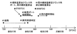
- the fuel injection amount of the port injector 11 is calculated for a predetermined cylinder and the port injector starts fuel injection for the next cycle, it is detected that the predetermined cylinder is an abnormal combustion generating cylinder in the current cycle. There is. This is because if the abnormal combustion detection timing is late, the injection stop control for the port injector 11 is not in time, and it may not be possible to shift to fuel cut. In this case, the fuel cut cannot be executed in the next cycle.
- FIG. 6 is a time chart showing an example of characteristic control in the system of the present embodiment.
- the compression top dead center is 0 °
- the position advanced by 20 ° is expressed as 20ATDC.
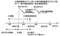
- the timing for calculating the fuel injection amount of the port injector 11 and the fuel injection amount of the in-cylinder injector 12 (# 1 injection amount calculation crank angle) of the first cylinder (# 1) is # 1 abnormal combustion. It is earlier than the judgment time. Therefore, the fuel cut cannot be executed in time, and fuel injection by the # 1 port injector 11 is started. In this case, the ECU 50 corrects the amount of fuel injected by the # 1 in-cylinder injector 12 by increasing. By this increase correction, the compression end temperature is lowered due to the rich A / F.
- FIG. 7 is a flowchart of a control routine executed by the ECU 50 in order to realize the above-described operation.
- This routine is the same as the routine shown in FIG. 4 except that the processing in steps S140 to S170 is replaced with the processing in steps S240 to S270.
- the same steps as those shown in FIG. 4 are denoted by the same reference numerals, and the description thereof is omitted or simplified.
- step S240 the ECU 50 determines whether or not the detection of the occurrence of abnormal combustion in step S130 is the first time in this routine. If it is the first time, the ECU 50 determines whether or not the current crank angle is on the retard side with respect to the injection amount calculation crank angle (step S250). In other words, the ECU 50 determines whether or not the injection amount calculation crank angle is faster than the crank angle at which the abnormal combustion occurrence cylinder is detected.
- step S250 if the current crank angle is more advanced than the injection amount calculation crank angle in step S250, the fuel injection amount for the next cycle of the port injector 11 has not yet been calculated at the current crank angle. In this case, since the fuel cut is executed in time, the second continuous occurrence prevention control described in the first embodiment is executed.
- step S250 is executed. This is because one cycle has passed and the fuel cut is in time.
- the amount of fuel injection can be corrected to increase.
- the fuel injection amount that has been increased in the first continuous occurrence prevention control can be further increased. Therefore, the compression end temperature is further lowered due to A / F rich, and as a result, the occurrence of abnormal combustion can be suppressed. Even if it occurs, it has the effect of reducing the in-cylinder peak pressure and weakening vibration / noise and engine damage. Further, in the next cycle, fuel cut is executed, and the occurrence of abnormal combustion can be more reliably suppressed.
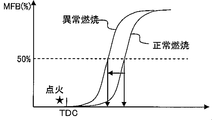
- FIG. 8 shows an example in which an abnormal combustion occurrence cylinder is detected based on the MFB 50% point.
- the abnormal combustion-occurring cylinder can be detected based on the difference in MFB 50% between normal combustion and abnormal combustion.
- MFB Mass Fraction Burnt
- the in-cylinder pressure until the end of combustion needs to be measured by the in-cylinder pressure sensor 14.
- the MFB 50% point calculation timing may be later than the injection amount calculation crank angle and the port injection start timing. Therefore, the characteristic control of the present embodiment described above is effective.
- FIG. 10 is an example in which an abnormal combustion occurrence cylinder is detected based on the in-cylinder peak pressure.
- the detection based on the in-cylinder peak pressure generation timing there is a high possibility that the result of the abnormal combustion determination is in time for the in-cylinder injection amount calculation crank angle.
- the characteristic control of the present embodiment described above is effective.
- the port injector 11 and the in-cylinder injector 12 are provided for each cylinder.
- fuel can be increased by additional injection by injecting fuel in synchronization with the intake stroke. Therefore, the present invention can be applied even if only the port injector 11 is configured.
- routine of FIG. 4 in the system of the first embodiment to the routine of FIG. 7 in the system of the second embodiment described above. Specifically, after the process of step S270 of the routine of FIG. 7, the process after step S140 of the routine of FIG. 4 may be added.
- the port injector 11 corresponds to the “port injector” in the third invention
- the in-cylinder injector 12 corresponds to the “in-cylinder injector” in the third invention.
- the “fuel cut execution means” in the third aspect of the present invention is realized by the ECU 50 executing the processing of steps S240 to S270.
Landscapes
- Engineering & Computer Science (AREA)
- Chemical & Material Sciences (AREA)
- Combustion & Propulsion (AREA)
- Mechanical Engineering (AREA)
- General Engineering & Computer Science (AREA)
- Signal Processing (AREA)
- Theoretical Computer Science (AREA)
- Combined Controls Of Internal Combustion Engines (AREA)
- Electrical Control Of Air Or Fuel Supplied To Internal-Combustion Engine (AREA)
- Output Control And Ontrol Of Special Type Engine (AREA)
- Electrical Control Of Ignition Timing (AREA)
- Fuel-Injection Apparatus (AREA)
Abstract
Description
尚、出願人は、本発明に関連するものとして、上記の文献を含めて、以下に記載する文献を認識している。
前記内燃機関の運転状態に応じて、前記点火プラグにより火花を発生させる基本点火時期を設定する点火時期設定手段と、
サイクル毎に、過給領域で異常燃焼が発生した異常燃焼発生気筒を検出する異常燃焼発生気筒検出手段と、
前記異常燃焼発生気筒について、前記燃料供給手段による燃料供給を停止する燃料カットを実行する燃料カット実行手段と、
前記異常燃焼発生気筒について、前記燃料カットを開始して数サイクルの間は、圧縮上死点と前記基本点火時期とのクランク角度幅を拡大するように点火時期を変更し、前記数サイクル経過後さらに、前記点火プラグによる火花発生を禁止する点火カットを実行する燃料カット実行中点火制御手段と、を備えることを特徴とする。
前記内燃機関の運転状態に応じて、前記燃料供給手段の基本燃料供給量を設定する燃料供給量設定手段と、
前記異常燃焼発生気筒について、所定サイクルの間、前記基本燃料供給量を増量補正する燃料供給量増量補正手段と、を更に備え、
前記燃料カット実行手段は、前記所定サイクル経過後に、前記異常燃焼発生気筒で未だに異常燃焼が発生している場合に、前記燃料カットを実行すること、を特徴とする。
前記燃料供給手段は、気筒内に直接燃料を噴射する筒内インジェクタと、吸気ポート内に燃料を噴射するポートインジェクタとを含み、
前記燃料カット実行手段は、所定気筒について、前記ポートインジェクタが次サイクルのための燃料噴射を開始した後に、前記異常燃焼発生気筒検出手段により前記所定気筒が現サイクルにおける異常燃焼発生気筒であると検出された場合に、前記筒内インジェクタの前記次サイクルのための燃料噴射量を増量補正し、前記次サイクルの次のサイクルから前記燃料カットを実行すること、を特徴とする。
[実施の形態1のシステム構成]
図1は、本発明の実施の形態1のシステム構成を表した概念図である。図1に示すシステムは、過給による排気量のダウンサイジングが図られた内燃機関(以下、単にエンジンとも記す。)10を備えている。内燃機関10は、車両等に搭載され、その動力源とされる。図1に示す内燃機関10は、直列4気筒型であるが、本発明において、気筒数および気筒配置はこれに限定されるものではない。便宜上、以下の説明において、第1気筒~第4気筒をそれぞれ#1~#4と表記する。
本実施形態のシステムのような過給エンジンでは、過給領域(例えば、低回転高負荷領域)において、突発的なプレイグニッション等の異常燃焼が発生し易い。この異常燃焼の発生要因として、オイルミストや、燃焼室やピストンに堆積したデポジットが挙げられる。この異常燃焼の連続発生は、振動や騒音の増加、エンジンのストレス増大の要因となる。
そこで、本実施の形態の過給機付き内燃機関の制御装置は、過給領域で異常燃焼が発生した異常燃焼発生気筒について燃料カットを実行する。ここで、燃料カットを開始して数サイクルの間は、圧縮上死点と基本点火時期とのクランク角度幅を拡大するように点火時期を変更する。さらに、上記数サイクル経過後は、燃料カットを継続しつつ点火カットを実行する。
これらの計算は、燃料噴射とは別ルーチンで行われる。
[実施の形態2のシステム構成]
次に、図5~図10を参照して本発明の実施の形態2について説明する。本実施形態のシステムは図5に示す構成において、ECU50に後述する図7のルーチンを実施させることで実現することができる。
そこで、本実施形態のシステムでは、所定気筒について、排気行程においてポートインジェクタ11が次サイクルための燃料噴射を開始した後に、上記所定気筒が現サイクルにおける異常燃焼発生気筒であると検出された場合に、筒内インジェクタ12の上記次サイクルの燃料噴射量を増量補正する。そして、上記次サイクルの次のサイクルから燃料カットを実行することとした。
上述した異常燃焼発生気筒が検出される時期について図8~図10を用いて説明する。図8は、MFB50%点に基づいて異常燃焼発生気筒を検出する例である。図9に示すように、正常燃焼時と異常燃焼時とのMFB50%点の違いに基づいて異常燃焼発生気筒を検出することができる。MFB(Mass Fraction Burnt)50%点を算出するため、燃焼終了までの筒内圧を筒内圧センサ14で計測する必要がある。その結果、図8に示すように、MFB50%点算出タイミングが噴射量算出クランク角及びポート噴射開始タイミングよりも遅くなる場合がある。そのため、上述した本実施形態の特徴的制御が有効である。
11 ポートインジェクタ
12 筒内インジェクタ
13 点火プラグ
14 筒内圧センサ
16 吸気通路
18 排気通路
20 吸気バルブ
22 排気バルブ
23 空燃比センサ
24 ターボチャージャ
24a タービン
24b コンプレッサ
26 触媒
28 エアクリーナ
30 エアフローメータ
31 過給圧センサ
32 インタークーラ
34 スロットルバルブ
36 吸気ポート
50 ECU
52 クランク角センサ
54 ノックセンサ
56 水温センサ
Claims (3)
- 気筒毎に、気筒内に燃料を供給する燃料供給手段と、点火プラグとを備える過給機付き内燃機関の制御装置において、
前記内燃機関の運転状態に応じて、前記点火プラグにより火花を発生させる基本点火時期を設定する点火時期設定手段と、
サイクル毎に、過給領域で異常燃焼が発生した異常燃焼発生気筒を検出する異常燃焼発生気筒検出手段と、
前記異常燃焼発生気筒について、前記燃料供給手段による燃料供給を停止する燃料カットを実行する燃料カット実行手段と、
前記異常燃焼発生気筒について、前記燃料カットを開始して数サイクルの間は、圧縮上死点と前記基本点火時期とのクランク角度幅を拡大するように点火時期を変更し、前記数サイクル経過後さらに、前記点火プラグによる火花発生を禁止する点火カットを実行する燃料カット実行中点火制御手段と、
を備えることを特徴とする過給機付き内燃機関の制御装置。 - 前記内燃機関の運転状態に応じて、前記燃料供給手段の基本燃料供給量を設定する燃料供給量設定手段と、
前記異常燃焼発生気筒について、所定サイクルの間、前記基本燃料供給量を増量補正する燃料供給量増量補正手段と、を更に備え、
前記燃料カット実行手段は、前記所定サイクル経過後に、前記異常燃焼発生気筒で未だに異常燃焼が発生している場合に、前記燃料カットを実行すること、
を特徴とする請求項1記載の過給機付き内燃機関の制御装置。 - 前記燃料供給手段は、気筒内に直接燃料を噴射する筒内インジェクタと、吸気ポート内に燃料を噴射するポートインジェクタとを含み、
前記燃料カット実行手段は、所定気筒について、前記ポートインジェクタが次サイクルのための燃料噴射を開始した後に、前記異常燃焼発生気筒検出手段により前記所定気筒が現サイクルにおける異常燃焼発生気筒であると検出された場合に、前記筒内インジェクタの前記次サイクルのための燃料噴射量を増量補正し、前記次サイクルの次のサイクルから前記燃料カットを実行すること、
を特徴とする請求項1又は2記載の過給機付き内燃機関の制御装置。
Priority Applications (12)
| Application Number | Priority Date | Filing Date | Title |
|---|---|---|---|
| PCT/JP2012/057188 WO2013140548A1 (ja) | 2012-03-21 | 2012-03-21 | 過給機付き内燃機関の制御装置 |
| IN7861DEN2014 IN2014DN07861A (ja) | 2012-03-21 | 2012-03-21 | |
| US14/386,385 US9850874B2 (en) | 2012-03-21 | 2012-03-21 | Controller of internal combustion engine with supercharger |
| AU2012374447A AU2012374447B2 (en) | 2012-03-21 | 2012-03-21 | Control device of internal combustion engine with supercharger |
| KR1020147026117A KR101542540B1 (ko) | 2012-03-21 | 2012-03-21 | 과급기 부착 내연 기관의 제어 장치 |
| EP12871771.7A EP2829723B1 (en) | 2012-03-21 | 2012-03-21 | Control device of internal combustion engine with supercharger |
| MYPI2014702634A MY174097A (en) | 2012-03-21 | 2012-03-21 | Controller of internal combustion engine with supercharger |
| CN201280071505.6A CN104204507B (zh) | 2012-03-21 | 2012-03-21 | 带增压器的内燃机的控制装置 |
| JP2014505879A JP5761449B2 (ja) | 2012-03-21 | 2012-03-21 | 過給機付き内燃機関の制御装置 |
| MX2014011269A MX2014011269A (es) | 2012-03-21 | 2012-03-21 | Controlador de motor de combustion interna con sobrealimentador. |
| RU2014138030/07A RU2572591C1 (ru) | 2012-03-21 | 2012-03-21 | Контроллер двигателя внутреннего сгорания с наддувом |
| PH12014502105A PH12014502105B1 (en) | 2012-03-21 | 2014-09-22 | Controller of internal combustion engine with supercharger |
Applications Claiming Priority (1)
| Application Number | Priority Date | Filing Date | Title |
|---|---|---|---|
| PCT/JP2012/057188 WO2013140548A1 (ja) | 2012-03-21 | 2012-03-21 | 過給機付き内燃機関の制御装置 |
Publications (1)
| Publication Number | Publication Date |
|---|---|
| WO2013140548A1 true WO2013140548A1 (ja) | 2013-09-26 |
Family
ID=49222042
Family Applications (1)
| Application Number | Title | Priority Date | Filing Date |
|---|---|---|---|
| PCT/JP2012/057188 Ceased WO2013140548A1 (ja) | 2012-03-21 | 2012-03-21 | 過給機付き内燃機関の制御装置 |
Country Status (11)
| Country | Link |
|---|---|
| US (1) | US9850874B2 (ja) |
| EP (1) | EP2829723B1 (ja) |
| JP (1) | JP5761449B2 (ja) |
| KR (1) | KR101542540B1 (ja) |
| CN (1) | CN104204507B (ja) |
| AU (1) | AU2012374447B2 (ja) |
| IN (1) | IN2014DN07861A (ja) |
| MX (1) | MX2014011269A (ja) |
| PH (1) | PH12014502105B1 (ja) |
| RU (1) | RU2572591C1 (ja) |
| WO (1) | WO2013140548A1 (ja) |
Families Citing this family (8)
| Publication number | Priority date | Publication date | Assignee | Title |
|---|---|---|---|---|
| KR101393567B1 (ko) * | 2012-10-30 | 2014-05-12 | 현대자동차 주식회사 | 차량 엔진의 실화 판정방법과 제어방법 및 제어장치 |
| US9670823B2 (en) * | 2015-03-24 | 2017-06-06 | GM Global Technology Operations LLC | Engine with a turbocharger cooling module |
| US10422296B2 (en) * | 2015-06-11 | 2019-09-24 | Ford Global Technologies, Llc | Methods and system for improving fuel delivery amount accuracy |
| US20180195455A1 (en) * | 2017-01-12 | 2018-07-12 | GM Global Technology Operations LLC | Engine combustion phasing control during transient state |
| JP7225593B2 (ja) * | 2018-07-26 | 2023-02-21 | マツダ株式会社 | 圧縮着火式エンジンの制御装置 |
| JP7314870B2 (ja) * | 2020-06-30 | 2023-07-26 | トヨタ自動車株式会社 | エンジン装置 |
| JP7354984B2 (ja) * | 2020-10-15 | 2023-10-03 | トヨタ自動車株式会社 | 内燃機関の判定装置 |
| JP2025018644A (ja) * | 2023-07-27 | 2025-02-06 | ヤンマーホールディングス株式会社 | エンジン装置及びエンジン装置の制御方法 |
Citations (7)
| Publication number | Priority date | Publication date | Assignee | Title |
|---|---|---|---|---|
| JPS61192836A (ja) | 1985-02-22 | 1986-08-27 | Toyota Motor Corp | 内燃機関の点火時期及び空燃比制御方法 |
| JPS62170754A (ja) | 1986-01-24 | 1987-07-27 | Toyota Motor Corp | 内燃機関の点火時期制御装置 |
| JPH0255876A (ja) | 1988-08-20 | 1990-02-26 | Toyota Motor Corp | 内燃機関の点火時期制御装置 |
| JPH06147073A (ja) | 1992-11-16 | 1994-05-27 | Mitsubishi Electric Corp | 内燃機関制御装置 |
| JP2008088826A (ja) * | 2006-09-29 | 2008-04-17 | Mitsubishi Heavy Ind Ltd | エンジンの異常燃焼時運転方法及び運転制御装置 |
| JP2009114942A (ja) * | 2007-11-06 | 2009-05-28 | Mazda Motor Corp | エンジンの始動制御装置 |
| JP2012002088A (ja) * | 2010-06-15 | 2012-01-05 | Nippon Soken Inc | 内燃機関の制御装置 |
Family Cites Families (25)
| Publication number | Priority date | Publication date | Assignee | Title |
|---|---|---|---|---|
| DE2747806A1 (de) * | 1977-10-25 | 1979-04-26 | Audi Nsu Auto Union Ag | Gemischverdichtende, fremdgezuendete brennkraftmaschine |
| JPS5765830A (en) * | 1980-10-13 | 1982-04-21 | Hitachi Ltd | Supercharger controller for internal combustion engine |
| JPS57179372A (en) * | 1981-04-28 | 1982-11-04 | Nippon Soken Inc | Ignition timing control system for internal-combustion engine equipped with supercharger |
| JPS62168950A (ja) * | 1986-01-20 | 1987-07-25 | Mazda Motor Corp | エンジンの点火装置 |
| JPS6365173A (ja) * | 1986-09-08 | 1988-03-23 | Mazda Motor Corp | エンジンの点火時期制御装置 |
| JPS6469775A (en) * | 1987-09-10 | 1989-03-15 | Nippon Denso Co | Ignitor for internal combustion engine |
| JPH01195949A (ja) * | 1988-02-01 | 1989-08-07 | Mitsubishi Electric Corp | エンジンの制御装置 |
| US5096016A (en) * | 1989-07-19 | 1992-03-17 | Toyota Jidosha Kabushiki Kaisha | Traction control system for a vehicle with an internal combustion engine |
| US5076098A (en) * | 1990-02-21 | 1991-12-31 | Nissan Motor Company, Limited | System for detecting combustion state in internal combustion engine |
| JP2874377B2 (ja) * | 1990-05-22 | 1999-03-24 | トヨタ自動車株式会社 | 内燃機関の点火装置 |
| WO1997013063A1 (en) * | 1995-10-02 | 1997-04-10 | Hitachi, Ltd. | Control device for an internal combustion engine |
| IT1298944B1 (it) * | 1998-02-24 | 2000-02-07 | Automobili Lamborghini Spa | Procedimento per rilevare il mancato scoppio in un motore a combustione interna e sistema che realizza tale procedimento |
| DE19912741A1 (de) * | 1999-03-22 | 2000-09-28 | Bosch Gmbh Robert | Zündsteuervorrichtung und -verfahren |
| US6371074B1 (en) * | 1999-06-29 | 2002-04-16 | John M. Keller | Method and apparatus for preventing backfiring in spark ignition, internal combustion engines |
| JP3968711B2 (ja) * | 2003-04-11 | 2007-08-29 | 株式会社デンソー | 内燃機関用点火装置およびそのイグナイタ |
| JP2005163696A (ja) * | 2003-12-04 | 2005-06-23 | Denso Corp | 内燃機関の失火検出装置 |
| US7079941B2 (en) * | 2004-03-29 | 2006-07-18 | Mazda Motor Corporation | Engine starting system |
| JP4424178B2 (ja) * | 2004-11-30 | 2010-03-03 | スズキ株式会社 | 多気筒エンジンの失火検出装置 |
| US7707822B2 (en) * | 2006-08-08 | 2010-05-04 | Denso Corporation | Cylinder air-fuel ratio controller for internal combustion engine |
| JP2008069713A (ja) * | 2006-09-14 | 2008-03-27 | Toyota Motor Corp | 内燃機関の燃焼制御装置 |
| US7757666B2 (en) * | 2007-11-05 | 2010-07-20 | Gm Global Technology Operations, Inc. | Cylinder fueling coordination for torque estimation and control |
| JP2010064664A (ja) * | 2008-09-12 | 2010-03-25 | Yamaha Motor Co Ltd | 舶用推進機 |
| JP5119216B2 (ja) * | 2009-07-21 | 2013-01-16 | トヨタ自動車株式会社 | 内燃機関の異常診断装置 |
| US8346418B2 (en) * | 2009-11-30 | 2013-01-01 | GM Global Technology Operations LLC | Method of smoothing output torque |
| US8224559B2 (en) * | 2010-01-21 | 2012-07-17 | GM Global Technology Operations LLC | Method and apparatus to monitor a mass airflow metering device in an internal combustion engine |
-
2012
- 2012-03-21 AU AU2012374447A patent/AU2012374447B2/en not_active Ceased
- 2012-03-21 CN CN201280071505.6A patent/CN104204507B/zh not_active Expired - Fee Related
- 2012-03-21 US US14/386,385 patent/US9850874B2/en not_active Expired - Fee Related
- 2012-03-21 JP JP2014505879A patent/JP5761449B2/ja not_active Expired - Fee Related
- 2012-03-21 EP EP12871771.7A patent/EP2829723B1/en not_active Not-in-force
- 2012-03-21 WO PCT/JP2012/057188 patent/WO2013140548A1/ja not_active Ceased
- 2012-03-21 KR KR1020147026117A patent/KR101542540B1/ko not_active Expired - Fee Related
- 2012-03-21 MX MX2014011269A patent/MX2014011269A/es active IP Right Grant
- 2012-03-21 IN IN7861DEN2014 patent/IN2014DN07861A/en unknown
- 2012-03-21 RU RU2014138030/07A patent/RU2572591C1/ru not_active IP Right Cessation
-
2014
- 2014-09-22 PH PH12014502105A patent/PH12014502105B1/en unknown
Patent Citations (7)
| Publication number | Priority date | Publication date | Assignee | Title |
|---|---|---|---|---|
| JPS61192836A (ja) | 1985-02-22 | 1986-08-27 | Toyota Motor Corp | 内燃機関の点火時期及び空燃比制御方法 |
| JPS62170754A (ja) | 1986-01-24 | 1987-07-27 | Toyota Motor Corp | 内燃機関の点火時期制御装置 |
| JPH0255876A (ja) | 1988-08-20 | 1990-02-26 | Toyota Motor Corp | 内燃機関の点火時期制御装置 |
| JPH06147073A (ja) | 1992-11-16 | 1994-05-27 | Mitsubishi Electric Corp | 内燃機関制御装置 |
| JP2008088826A (ja) * | 2006-09-29 | 2008-04-17 | Mitsubishi Heavy Ind Ltd | エンジンの異常燃焼時運転方法及び運転制御装置 |
| JP2009114942A (ja) * | 2007-11-06 | 2009-05-28 | Mazda Motor Corp | エンジンの始動制御装置 |
| JP2012002088A (ja) * | 2010-06-15 | 2012-01-05 | Nippon Soken Inc | 内燃機関の制御装置 |
Non-Patent Citations (1)
| Title |
|---|
| See also references of EP2829723A4 |
Also Published As
| Publication number | Publication date |
|---|---|
| AU2012374447B2 (en) | 2015-06-11 |
| IN2014DN07861A (ja) | 2015-04-24 |
| JP5761449B2 (ja) | 2015-08-12 |
| KR20140133584A (ko) | 2014-11-19 |
| PH12014502105A1 (en) | 2014-12-10 |
| MX2014011269A (es) | 2014-10-15 |
| JPWO2013140548A1 (ja) | 2015-08-03 |
| EP2829723B1 (en) | 2017-04-26 |
| RU2572591C1 (ru) | 2016-01-20 |
| KR101542540B1 (ko) | 2015-08-06 |
| EP2829723A1 (en) | 2015-01-28 |
| US20150047606A1 (en) | 2015-02-19 |
| US9850874B2 (en) | 2017-12-26 |
| AU2012374447A1 (en) | 2014-10-09 |
| CN104204507B (zh) | 2016-07-27 |
| PH12014502105B1 (en) | 2014-12-10 |
| EP2829723A4 (en) | 2015-10-07 |
| CN104204507A (zh) | 2014-12-10 |
Similar Documents
| Publication | Publication Date | Title |
|---|---|---|
| JP5761449B2 (ja) | 過給機付き内燃機関の制御装置 | |
| JP5565364B2 (ja) | 火花点火式エンジンの異常燃焼検出方法および火花点火式エンジン | |
| EP3514359B1 (en) | Method to be performed by a control device for an engine, and engine | |
| US8910615B2 (en) | Control apparatus for internal combustion engine | |
| JP2009019538A (ja) | 筒内噴射式内燃機関の制御装置 | |
| JP6549551B2 (ja) | 内燃機関の制御装置 | |
| JP2009108777A (ja) | 圧縮着火式内燃機関 | |
| JP4868242B2 (ja) | 車両用エンジンの制御装置 | |
| JP5625842B2 (ja) | 内燃機関の制御装置 | |
| JP4806998B2 (ja) | 内燃機関 | |
| JP7712181B2 (ja) | エンジン制御装置及びエンジン制御方法 | |
| JP5487978B2 (ja) | 内燃機関の制御装置 | |
| JP6054766B2 (ja) | 内燃機関の制御装置 | |
| JP2011208540A (ja) | 内燃機関の制御装置 | |
| JP2015014229A (ja) | 内燃機関の異常燃焼回避装置 | |
| JP2010265815A (ja) | 内燃機関の燃料噴射システム | |
| JP2010138720A (ja) | エンジンの点火制御装置 | |
| JP5892311B2 (ja) | 内燃機関のノック制御装置 | |
| JP4884516B2 (ja) | 内燃機関の点火制御装置 | |
| JP2012026395A (ja) | 内燃機関の制御装置 | |
| JP2025018644A (ja) | エンジン装置及びエンジン装置の制御方法 | |
| JP2008267292A (ja) | 内燃機関の制御システム | |
| WO2015063874A1 (ja) | 火花点火式エンジンの制御装置 | |
| JP2020084891A (ja) | 副室付内燃機関の制御装置 | |
| JP2006057494A (ja) | 内燃機関の減速制御装置 |
Legal Events
| Date | Code | Title | Description |
|---|---|---|---|
| 121 | Ep: the epo has been informed by wipo that ep was designated in this application |
Ref document number: 12871771 Country of ref document: EP Kind code of ref document: A1 |
|
| ENP | Entry into the national phase |
Ref document number: 2014505879 Country of ref document: JP Kind code of ref document: A |
|
| ENP | Entry into the national phase |
Ref document number: 20147026117 Country of ref document: KR Kind code of ref document: A |
|
| REEP | Request for entry into the european phase |
Ref document number: 2012871771 Country of ref document: EP |
|
| WWE | Wipo information: entry into national phase |
Ref document number: IDP00201405620 Country of ref document: ID Ref document number: 14386385 Country of ref document: US Ref document number: MX/A/2014/011269 Country of ref document: MX Ref document number: 2012871771 Country of ref document: EP |
|
| NENP | Non-entry into the national phase |
Ref country code: DE |
|
| ENP | Entry into the national phase |
Ref document number: 2012374447 Country of ref document: AU Date of ref document: 20120321 Kind code of ref document: A |
|
| ENP | Entry into the national phase |
Ref document number: 2014138030 Country of ref document: RU Kind code of ref document: A |
|
| REG | Reference to national code |
Ref country code: BR Ref legal event code: B01A Ref document number: 112014023351 Country of ref document: BR |
|
| ENP | Entry into the national phase |
Ref document number: 112014023351 Country of ref document: BR Kind code of ref document: A2 Effective date: 20140919 |