WO2013140577A1 - 内燃機関の制御装置 - Google Patents
内燃機関の制御装置 Download PDFInfo
- Publication number
- WO2013140577A1 WO2013140577A1 PCT/JP2012/057357 JP2012057357W WO2013140577A1 WO 2013140577 A1 WO2013140577 A1 WO 2013140577A1 JP 2012057357 W JP2012057357 W JP 2012057357W WO 2013140577 A1 WO2013140577 A1 WO 2013140577A1
- Authority
- WO
- WIPO (PCT)
- Prior art keywords
- temperature
- catalyst
- cylinder wall
- cylinder
- wall temperature
- Prior art date
- Legal status (The legal status is an assumption and is not a legal conclusion. Google has not performed a legal analysis and makes no representation as to the accuracy of the status listed.)
- Ceased
Links
Images




Classifications
-
- F—MECHANICAL ENGINEERING; LIGHTING; HEATING; WEAPONS; BLASTING
- F02—COMBUSTION ENGINES; HOT-GAS OR COMBUSTION-PRODUCT ENGINE PLANTS
- F02D—CONTROLLING COMBUSTION ENGINES
- F02D17/00—Controlling engines by cutting out individual cylinders; Rendering engines inoperative or idling
-
- F—MECHANICAL ENGINEERING; LIGHTING; HEATING; WEAPONS; BLASTING
- F02—COMBUSTION ENGINES; HOT-GAS OR COMBUSTION-PRODUCT ENGINE PLANTS
- F02D—CONTROLLING COMBUSTION ENGINES
- F02D13/00—Controlling the engine output power by varying inlet or exhaust valve operating characteristics, e.g. timing
- F02D13/02—Controlling the engine output power by varying inlet or exhaust valve operating characteristics, e.g. timing during engine operation
- F02D13/0203—Variable control of intake and exhaust valves
-
- F—MECHANICAL ENGINEERING; LIGHTING; HEATING; WEAPONS; BLASTING
- F01—MACHINES OR ENGINES IN GENERAL; ENGINE PLANTS IN GENERAL; STEAM ENGINES
- F01N—GAS-FLOW SILENCERS OR EXHAUST APPARATUS FOR MACHINES OR ENGINES IN GENERAL; GAS-FLOW SILENCERS OR EXHAUST APPARATUS FOR INTERNAL-COMBUSTION ENGINES
- F01N3/00—Exhaust or silencing apparatus having means for purifying, rendering innocuous, or otherwise treating exhaust
- F01N3/08—Exhaust or silencing apparatus having means for purifying, rendering innocuous, or otherwise treating exhaust for rendering innocuous
- F01N3/10—Exhaust or silencing apparatus having means for purifying, rendering innocuous, or otherwise treating exhaust for rendering innocuous by thermal or catalytic conversion of noxious components of exhaust
- F01N3/18—Exhaust or silencing apparatus having means for purifying, rendering innocuous, or otherwise treating exhaust for rendering innocuous by thermal or catalytic conversion of noxious components of exhaust characterised by methods of operation; Control
- F01N3/20—Exhaust or silencing apparatus having means for purifying, rendering innocuous, or otherwise treating exhaust for rendering innocuous by thermal or catalytic conversion of noxious components of exhaust characterised by methods of operation; Control specially adapted for catalytic conversion
- F01N3/2006—Periodically heating or cooling catalytic reactors, e.g. at cold starting or overheating
-
- F—MECHANICAL ENGINEERING; LIGHTING; HEATING; WEAPONS; BLASTING
- F02—COMBUSTION ENGINES; HOT-GAS OR COMBUSTION-PRODUCT ENGINE PLANTS
- F02D—CONTROLLING COMBUSTION ENGINES
- F02D13/00—Controlling the engine output power by varying inlet or exhaust valve operating characteristics, e.g. timing
- F02D13/02—Controlling the engine output power by varying inlet or exhaust valve operating characteristics, e.g. timing during engine operation
- F02D13/0203—Variable control of intake and exhaust valves
- F02D13/0215—Variable control of intake and exhaust valves changing the valve timing only
-
- F—MECHANICAL ENGINEERING; LIGHTING; HEATING; WEAPONS; BLASTING
- F02—COMBUSTION ENGINES; HOT-GAS OR COMBUSTION-PRODUCT ENGINE PLANTS
- F02D—CONTROLLING COMBUSTION ENGINES
- F02D15/00—Varying compression ratio
-
- F—MECHANICAL ENGINEERING; LIGHTING; HEATING; WEAPONS; BLASTING
- F02—COMBUSTION ENGINES; HOT-GAS OR COMBUSTION-PRODUCT ENGINE PLANTS
- F02D—CONTROLLING COMBUSTION ENGINES
- F02D19/00—Controlling engines characterised by their use of non-liquid fuels, pluralities of fuels, or non-fuel substances added to the combustible mixtures
- F02D19/06—Controlling engines characterised by their use of non-liquid fuels, pluralities of fuels, or non-fuel substances added to the combustible mixtures peculiar to engines working with pluralities of fuels, e.g. alternatively with light and heavy fuel oil, other than engines indifferent to the fuel consumed
- F02D19/08—Controlling engines characterised by their use of non-liquid fuels, pluralities of fuels, or non-fuel substances added to the combustible mixtures peculiar to engines working with pluralities of fuels, e.g. alternatively with light and heavy fuel oil, other than engines indifferent to the fuel consumed simultaneously using pluralities of fuels
- F02D19/082—Premixed fuels, i.e. emulsions or blends
- F02D19/084—Blends of gasoline and alcohols, e.g. E85
-
- F—MECHANICAL ENGINEERING; LIGHTING; HEATING; WEAPONS; BLASTING
- F02—COMBUSTION ENGINES; HOT-GAS OR COMBUSTION-PRODUCT ENGINE PLANTS
- F02D—CONTROLLING COMBUSTION ENGINES
- F02D19/00—Controlling engines characterised by their use of non-liquid fuels, pluralities of fuels, or non-fuel substances added to the combustible mixtures
- F02D19/06—Controlling engines characterised by their use of non-liquid fuels, pluralities of fuels, or non-fuel substances added to the combustible mixtures peculiar to engines working with pluralities of fuels, e.g. alternatively with light and heavy fuel oil, other than engines indifferent to the fuel consumed
- F02D19/08—Controlling engines characterised by their use of non-liquid fuels, pluralities of fuels, or non-fuel substances added to the combustible mixtures peculiar to engines working with pluralities of fuels, e.g. alternatively with light and heavy fuel oil, other than engines indifferent to the fuel consumed simultaneously using pluralities of fuels
- F02D19/082—Premixed fuels, i.e. emulsions or blends
- F02D19/085—Control based on the fuel type or composition
- F02D19/087—Control based on the fuel type or composition with determination of densities, viscosities, composition, concentration or mixture ratios of fuels
-
- F—MECHANICAL ENGINEERING; LIGHTING; HEATING; WEAPONS; BLASTING
- F02—COMBUSTION ENGINES; HOT-GAS OR COMBUSTION-PRODUCT ENGINE PLANTS
- F02D—CONTROLLING COMBUSTION ENGINES
- F02D41/00—Electrical control of supply of combustible mixture or its constituents
- F02D41/02—Circuit arrangements for generating control signals
- F02D41/021—Introducing corrections for particular conditions exterior to the engine
- F02D41/0235—Introducing corrections for particular conditions exterior to the engine in relation with the state of the exhaust gas treating apparatus
- F02D41/024—Introducing corrections for particular conditions exterior to the engine in relation with the state of the exhaust gas treating apparatus to increase temperature of the exhaust gas treating apparatus
- F02D41/0245—Introducing corrections for particular conditions exterior to the engine in relation with the state of the exhaust gas treating apparatus to increase temperature of the exhaust gas treating apparatus by increasing temperature of the exhaust gas leaving the engine
-
- F—MECHANICAL ENGINEERING; LIGHTING; HEATING; WEAPONS; BLASTING
- F02—COMBUSTION ENGINES; HOT-GAS OR COMBUSTION-PRODUCT ENGINE PLANTS
- F02D—CONTROLLING COMBUSTION ENGINES
- F02D41/00—Electrical control of supply of combustible mixture or its constituents
- F02D41/02—Circuit arrangements for generating control signals
- F02D41/04—Introducing corrections for particular operating conditions
- F02D41/12—Introducing corrections for particular operating conditions for deceleration
- F02D41/123—Introducing corrections for particular operating conditions for deceleration the fuel injection being cut-off
-
- F—MECHANICAL ENGINEERING; LIGHTING; HEATING; WEAPONS; BLASTING
- F02—COMBUSTION ENGINES; HOT-GAS OR COMBUSTION-PRODUCT ENGINE PLANTS
- F02D—CONTROLLING COMBUSTION ENGINES
- F02D41/00—Electrical control of supply of combustible mixture or its constituents
- F02D41/02—Circuit arrangements for generating control signals
- F02D41/04—Introducing corrections for particular operating conditions
- F02D41/12—Introducing corrections for particular operating conditions for deceleration
- F02D41/123—Introducing corrections for particular operating conditions for deceleration the fuel injection being cut-off
- F02D41/126—Introducing corrections for particular operating conditions for deceleration the fuel injection being cut-off transitional corrections at the end of the cut-off period
-
- F—MECHANICAL ENGINEERING; LIGHTING; HEATING; WEAPONS; BLASTING
- F02—COMBUSTION ENGINES; HOT-GAS OR COMBUSTION-PRODUCT ENGINE PLANTS
- F02B—INTERNAL-COMBUSTION PISTON ENGINES; COMBUSTION ENGINES IN GENERAL
- F02B75/00—Other engines
- F02B75/12—Other methods of operation
- F02B2075/125—Direct injection in the combustion chamber for spark ignition engines, i.e. not in pre-combustion chamber
-
- F—MECHANICAL ENGINEERING; LIGHTING; HEATING; WEAPONS; BLASTING
- F02—COMBUSTION ENGINES; HOT-GAS OR COMBUSTION-PRODUCT ENGINE PLANTS
- F02D—CONTROLLING COMBUSTION ENGINES
- F02D41/00—Electrical control of supply of combustible mixture or its constituents
- F02D41/0002—Controlling intake air
- F02D2041/001—Controlling intake air for engines with variable valve actuation
-
- F—MECHANICAL ENGINEERING; LIGHTING; HEATING; WEAPONS; BLASTING
- F02—COMBUSTION ENGINES; HOT-GAS OR COMBUSTION-PRODUCT ENGINE PLANTS
- F02D—CONTROLLING COMBUSTION ENGINES
- F02D2200/00—Input parameters for engine control
- F02D2200/02—Input parameters for engine control the parameters being related to the engine
- F02D2200/021—Engine temperature
-
- F—MECHANICAL ENGINEERING; LIGHTING; HEATING; WEAPONS; BLASTING
- F02—COMBUSTION ENGINES; HOT-GAS OR COMBUSTION-PRODUCT ENGINE PLANTS
- F02D—CONTROLLING COMBUSTION ENGINES
- F02D2200/00—Input parameters for engine control
- F02D2200/02—Input parameters for engine control the parameters being related to the engine
- F02D2200/08—Exhaust gas treatment apparatus parameters
- F02D2200/0802—Temperature of the exhaust gas treatment apparatus
-
- Y—GENERAL TAGGING OF NEW TECHNOLOGICAL DEVELOPMENTS; GENERAL TAGGING OF CROSS-SECTIONAL TECHNOLOGIES SPANNING OVER SEVERAL SECTIONS OF THE IPC; TECHNICAL SUBJECTS COVERED BY FORMER USPC CROSS-REFERENCE ART COLLECTIONS [XRACs] AND DIGESTS
- Y02—TECHNOLOGIES OR APPLICATIONS FOR MITIGATION OR ADAPTATION AGAINST CLIMATE CHANGE
- Y02T—CLIMATE CHANGE MITIGATION TECHNOLOGIES RELATED TO TRANSPORTATION
- Y02T10/00—Road transport of goods or passengers
- Y02T10/10—Internal combustion engine [ICE] based vehicles
- Y02T10/12—Improving ICE efficiencies
-
- Y—GENERAL TAGGING OF NEW TECHNOLOGICAL DEVELOPMENTS; GENERAL TAGGING OF CROSS-SECTIONAL TECHNOLOGIES SPANNING OVER SEVERAL SECTIONS OF THE IPC; TECHNICAL SUBJECTS COVERED BY FORMER USPC CROSS-REFERENCE ART COLLECTIONS [XRACs] AND DIGESTS
- Y02—TECHNOLOGIES OR APPLICATIONS FOR MITIGATION OR ADAPTATION AGAINST CLIMATE CHANGE
- Y02T—CLIMATE CHANGE MITIGATION TECHNOLOGIES RELATED TO TRANSPORTATION
- Y02T10/00—Road transport of goods or passengers
- Y02T10/10—Internal combustion engine [ICE] based vehicles
- Y02T10/30—Use of alternative fuels, e.g. biofuels
Definitions
- the present invention relates to a control device for an internal combustion engine, and more particularly, to a control device for an internal combustion engine that controls valve timing during fuel cut.
- the valve timing is controlled during the fuel cut, so that the heat around the combustion chamber is transmitted to the catalyst using fresh air flowing into the cylinder as a medium.
- the wall surface temperature of the combustion chamber is low, heat conduction to the fresh air does not occur, and the heat of the fresh air heated by the compression in the cylinder is absorbed by the wall surface of the combustion chamber.
- the temperature of the fresh air does not increase in the control according to the conventional technology, there is a problem that the decrease in the catalyst temperature cannot be sufficiently suppressed.
- the present invention has been made to solve the above-described problems, and an object of the present invention is to improve the combustibility while maintaining the exhaust purification catalyst at an appropriate temperature during the fuel cut.
- An object of the present invention is to provide a control device for an internal combustion engine.
- an exhaust purification catalyst that purifies exhaust gas discharged from a cylinder of an internal combustion engine;
- An exhaust valve timing variable mechanism for variably setting the valve opening characteristics of the exhaust valve;
- Catalyst temperature acquisition means for detecting or estimating the temperature of the exhaust purification catalyst as an actual catalyst temperature;
- Target catalyst temperature setting means for setting a catalyst temperature suitable for the operation of the exhaust purification catalyst as a target catalyst temperature;
- Cylinder wall temperature detecting means for detecting cylinder wall temperature which is the wall surface temperature of the cylinder;
- a required cylinder wall temperature calculating means for calculating a required cylinder wall temperature as a required cylinder wall temperature when returning from the fuel cut;
- the exhaust valve timing variable mechanism controls the exhaust gas based on the magnitude relationship between the actual catalyst temperature and the target catalyst temperature and the magnitude relationship between the cylinder wall temperature and the required cylinder wall temperature.
- Temperature balance control means for controlling valve opening characteristics; It is characterized by providing.
- the second invention comprises an alcohol concentration detection means for detecting the alcohol concentration in the fuel,
- the required cylinder wall temperature calculating means calculates the required cylinder wall temperature to a higher temperature as the alcohol concentration in the fuel is higher.
- the target catalyst temperature includes a predetermined activity lowering temperature corresponding to a lower limit value of a catalyst temperature range in which the exhaust purification catalyst is activated,
- the temperature balance control means compresses the opening timing of the exhaust valve at a compression top dead center.
- the catalyst low temperature / cylinder high temperature control means set immediately after is provided.
- the fourth invention includes an intake valve timing variable mechanism that variably sets the valve opening characteristic of the intake valve, When the temperature difference between the actual catalyst temperature and the activity lowering temperature is larger than a predetermined large temperature difference determination value, the temperature balance control means takes the intake valve closing timing into the intake valve timing by the intake valve timing variable mechanism. The control means at the time of catalyst cryogenic temperature set near the bottom dead center is provided.
- the 5th invention is equipped with the compression ratio variable mechanism which can set the mechanical compression ratio of the said cylinder variably,
- the temperature balance control means increases the mechanical compression ratio by the variable compression ratio mechanism when the actual catalyst temperature is lower than the activity lowering temperature and the cylinder wall temperature is lower than the required cylinder wall temperature.
- a temperature raising means for raising the gas temperature in the cylinder and the cylinder wall temperature.
- the temperature balance control means closes the intake valve when the actual catalyst temperature is lower than the activity lowering temperature and the cylinder wall temperature is lower than the required cylinder wall temperature.
- a temperature raising means for setting the valve timing in the vicinity of the intake bottom dead center and raising the gas temperature in the cylinder and the cylinder wall temperature.
- the seventh invention comprises in-cylinder temperature estimation means for estimating an in-cylinder temperature that is a temperature in the cylinder at the compression top dead center based on at least the alcohol concentration in the fuel,
- the temperature balance control means includes cylinder wall temperature increasing means for setting the opening timing of the exhaust valve to a timing at which the cylinder wall temperature and the in-cylinder temperature become equal.
- the target catalyst temperature includes a predetermined catalyst deterioration temperature corresponding to a lower limit value of a catalyst temperature range in which deterioration of the exhaust purification catalyst proceeds
- the temperature balance control means determines the opening timing of the exhaust valve as the cylinder wall temperature.
- exhaust temperature lowering priority means for setting the timing at which the in-cylinder temperature becomes equal.
- a ninth invention includes a compression ratio variable mechanism capable of variably setting the mechanical compression ratio of the cylinder,
- the temperature balance control means increases the mechanical compression ratio by the variable compression ratio mechanism when the actual catalyst temperature is equal to or higher than the catalyst deterioration temperature and the cylinder wall temperature is lower than the required cylinder wall temperature.
- temperature adjusting means for raising the cylinder wall temperature and lowering the exhaust temperature.
- a tenth aspect of the invention includes an intake valve timing variable mechanism that variably sets the valve opening characteristic of the intake valve,
- the temperature balance control means closes the intake valve by the intake valve timing variable mechanism when the actual catalyst temperature is equal to or higher than the catalyst deterioration temperature and the cylinder wall temperature is lower than the required cylinder wall temperature.
- In-cylinder temperature raising means for setting the timing in the vicinity of the intake bottom dead center is provided.
- both temperatures can be controlled in a well-balanced manner so that the actual catalyst temperature becomes a temperature suitable for the operation of the exhaust purification catalyst and the cylinder wall temperature is close to the required cylinder wall temperature. Therefore, when the fuel is cut, it is possible to prevent the catalyst from deteriorating at a high temperature or the catalyst from becoming low temperature and the exhaust emission from being deteriorated. Deterioration can be suppressed.
- the required cylinder wall temperature is calculated to be a high temperature, and the cylinder wall temperature is determined according to the calculation result. Can be raised. Therefore, the cylinder wall temperature can be appropriately controlled according to the alcohol concentration in the fuel.
- the opening timing of the exhaust valve can be set immediately after the compression top dead center. Thereby, the temperature of the exhaust gas supplied to a catalyst can be raised and the warming-up property of a catalyst can be improved.
- the closing timing of the intake valve can be set in the vicinity of the intake bottom dead center.
- the in-cylinder temperature at the compression top dead center can be raised, the exhaust gas temperature can be raised, and the warm-up property of the catalyst can be further improved.
- the mechanical compression ratio can be increased by the compression ratio variable mechanism.
- the in-cylinder temperature at the compression top dead center can be increased, and the cylinder wall temperature can be increased by increasing the cooling loss.
- the exhaust gas temperature can be raised together with the in-cylinder gas temperature, and the warm-up property of the catalyst can be improved.
- the valve closing timing of the intake valve is set in the vicinity of the intake bottom dead center, and the gas temperature in the cylinder and the cylinder wall temperature are increased. be able to. Thereby, the warm-up property of the catalyst can also be improved.
- the valve opening timing of the exhaust valve is synchronized with the timing at which the cylinder wall temperature and the in-cylinder temperature become equal, thereby reducing the heat absorption amount from the cylinder wall surface to the in-cylinder gas.
- the temperature can be raised.
- the alcohol concentration in the fuel is reflected in the estimated value of the in-cylinder temperature, when the alcohol concentration is high, the amount of increase in the cylinder wall temperature can be increased, and according to the alcohol concentration
- the cylinder wall temperature can be appropriately controlled.
- the opening timing of the exhaust valve is determined based on the cylinder wall temperature and the in-cylinder temperature. It can be advanced to the same timing. Thereby, the amount of heat absorption from the cylinder wall surface to the in-cylinder gas can be reduced, and the temperature of the in-cylinder gas and the exhaust gas temperature can be relatively lowered. As a result, the catalyst temperature can be lowered and the deterioration of the catalyst can be suppressed.
- the mechanical compression ratio is increased by the variable compression ratio mechanism to increase the cylinder wall temperature.
- the exhaust temperature can be relatively lowered. Thereby, a catalyst can be protected from deterioration at high temperature.
- the closing timing of the intake valve is set near the intake bottom dead center.
- the actual compression ratio can be increased.
- Embodiment 1 of this invention It is a block diagram for demonstrating the system configuration
- FIG. 1 is a configuration diagram for explaining a system configuration according to the first embodiment of the present invention.
- the system according to the present embodiment includes an engine 10 as a multi-cylinder internal combustion engine.
- FIG. 1 illustrates only one cylinder of the engine 10, the present invention is applied to an engine having an arbitrary number of cylinders including a single cylinder.
- the engine 10 is mounted on a vehicle such as FFV (Flexible-Fuel Vehicle), for example, and alcohol fuel containing ethanol or the like can be used.
- FFV Flexible-Fuel Vehicle
- a combustion chamber 14 is defined by a piston 12, and the piston 12 is connected to a crankshaft 16 of the engine.
- the engine 10 also includes an intake passage 18 that sucks intake air into each cylinder, and an exhaust passage 20 through which exhaust gas is discharged from each cylinder.
- the intake passage 18 is provided with an electronically controlled throttle valve 22 that adjusts the intake air amount based on the accelerator opening and the like.
- Exhaust gas purification catalysts 24 and 26 for purifying exhaust gas are disposed in the exhaust passage 20. As these catalysts 24 and 26, a three-way catalyst can be used.
- Each cylinder has a fuel injection valve 28 for injecting fuel into the combustion chamber 14, an ignition plug 30 for igniting an air-fuel mixture in the cylinder, and an intake valve 32 for opening and closing the intake passage 18 with respect to the cylinder.
- An exhaust valve 34 for opening and closing the exhaust passage 20 with respect to the inside of the cylinder is provided.
- the engine 10 variably changes the valve opening characteristics of the intake valve 32 and the exhaust valve 34 as an intake valve timing variable mechanism that variably sets the valve opening characteristics (opening / closing timing, phase, etc.) of the intake valve 32.
- an exhaust variable valve mechanism 38 as an exhaust valve timing variable mechanism to be set.
- variable valve mechanisms 36 and 38 for example, as described in Japanese Patent Application Laid-Open No. 2006-97602, a variable operating angle type variable operating mechanism capable of changing the operating angle along with the valve opening / closing timing.
- a valve mechanism may be used.
- the engine 10 includes a compression ratio variable mechanism 40 that can variably set the mechanical compression ratio of each cylinder.
- the compression ratio variable mechanism 40 has a known configuration as described in, for example, Japanese Unexamined Patent Publication No. 2012-7591. More specifically, the variable compression ratio mechanism 40 moves the cylinder block and the crankcase relative to each other to change the distance between the cylinder block and the crankshaft. The value of top dead center cylinder volume + stroke volume) / top dead center cylinder volume is variable. Note that the intake variable valve mechanism 36 and the compression ratio variable mechanism 40 described above are not essential components in the present invention, and may be mounted only when necessary in each control described later.
- the system of the present embodiment includes a sensor system including various sensors necessary for driving the engine and the vehicle, and an ECU (Electronic Control Unit) 60 for controlling the operating state of the engine 10.
- the crank angle sensor 42 outputs a signal synchronized with the rotation of the crankshaft 16
- the air flow sensor 44 detects the intake air amount
- the water temperature sensor 46 detects the water temperature of the engine cooling water. Thw is detected.
- the water temperature Thw is adopted as a parameter corresponding to the wall surface temperature (cylinder wall temperature) of the cylinder (combustion chamber 14), and the water temperature sensor 46 constitutes a cylinder wall temperature detecting means.
- the main air-fuel ratio sensor 48 detects the exhaust air-fuel ratio as a continuous value on the upstream side of the exhaust purification catalyst 24.
- the sub O2 sensor 50 detects the oxygen concentration in the exhaust gas between the exhaust purification catalysts 24 and 26.
- the catalyst temperature sensor 52 constitutes catalyst temperature acquisition means for detecting the temperature of the exhaust purification catalyst 24 as the actual catalyst temperature Ts.
- the actual catalyst temperature is estimated based on parameters (for example, the integrated value of the intake air amount, the exhaust air-fuel ratio) reflecting the operating state of the engine without using the catalyst temperature sensor 52.
- the alcohol concentration sensor 54 constitutes alcohol concentration detection means for detecting the alcohol concentration in the fuel.
- the sensor system includes a throttle sensor that detects the throttle opening, an accelerator opening sensor that detects the accelerator opening, an intake air temperature sensor that detects the intake air temperature, and the like.
- the ECU 60 is configured by an arithmetic processing unit including a storage circuit such as a ROM, a RAM, and a nonvolatile memory and an input / output circuit, and the various sensors described above are connected to the input side of the ECU 60.
- Various actuators including the throttle valve 22, the fuel injection valve 28, the spark plug 30, the variable valve mechanisms 36 and 38, the compression ratio variable mechanism 40 and the like are connected to the output side of the ECU 60. Then, the ECU 60 detects operation information of the engine with a sensor system, and performs operation control by driving each actuator based on the detection result.
- the engine speed and the crank angle are detected based on the output of the crank angle sensor 42, and the engine load is calculated based on the intake air amount detected by the air flow sensor 44 and the engine speed. Further, the fuel injection timing, ignition timing, etc. are determined based on the detected value of the crank angle. Then, the fuel injection amount is calculated based on the intake air amount, the engine load, etc., and the fuel injection valve 28 is driven and the spark plug 30 is driven.
- the ECU 60 executes a known fuel cut when the engine is in a decelerating state, for example. When the engine is shifted from the decelerating state to the accelerating state, the ECU 60 ends the fuel cut and performs normal fuel injection control.
- the ECU 60 constitutes target catalyst temperature setting means for setting a catalyst temperature suitable for the operation of the exhaust purification catalyst 24 as a target catalyst temperature. More specifically, the ECU 60 corresponds to a predetermined catalyst deterioration temperature T1 corresponding to the lower limit value of the catalyst temperature range where the deterioration of the exhaust purification catalyst 24 proceeds and a lower limit value of the catalyst temperature range where the exhaust purification catalyst 24 is activated.
- the predetermined activity lowering temperature T2 is stored in advance.
- the catalyst deterioration temperature T1 is set to a high temperature of about 800 ° C., for example, and the activity lowering temperature T2 is set to a low temperature of about 400 ° C., for example.
- the target catalyst temperature is set as a temperature range not lower than the activity lowering temperature T2 and not higher than the catalyst deterioration temperature T1, and the actual catalyst temperature Ts is controlled to fall within this temperature range (T1 ⁇ Ts ⁇ T2).
- the present embodiment is characterized in that temperature balance control is executed when fuel cut is executed.
- both temperatures are controlled in a balanced manner so that the actual catalyst temperature Ts and the cylinder wall temperature (in this embodiment, the water temperature Thw) are close to the individual target temperatures.
- the temperature balance control is based on the magnitude relationship between the actual catalyst temperature Ts and the target catalyst temperature (catalyst degradation temperature T1 or activity decrease temperature T2) and the magnitude relationship between the water temperature Thw and the required cylinder wall temperature Ty. Based on this, the valve opening characteristics of the intake valve 32 and the exhaust valve 34 are controlled.
- the specific processing of the temperature balance control will be described later. First, the required cylinder wall temperature Ty and the in-cylinder temperature Th used in the control will be described.
- the required cylinder wall temperature Ty corresponds to a target value of the cylinder wall temperature (water temperature Thw) required at the time of return from the fuel cut, and as shown in FIG. 4 described later, at least the alcohol concentration in the fuel Calculated based on The required cylinder wall temperature Ty is calculated based on the alcohol concentration for the following reason.
- the required cylinder wall temperature Ty corresponds to a cylinder wall temperature that can realize exhaust emission equivalent to non-alcohol fuel (gasoline or the like) when returning from a fuel cut.
- Alcohol has a high boiling point and is difficult to vaporize, so NMOG emissions (total amount of non-methane organic gases, hydrocarbons, etc.
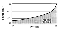
- the required cylinder wall temperature Ty is calculated based on the alcohol concentration in the fuel, and is set to a higher temperature as the alcohol concentration in the fuel is higher as shown in FIG.
- FIG. 2 is a timing chart showing the state of each control parameter when returning from a fuel cut.
- the solid line in this figure shows the control when the alcohol concentration in the fuel is high in the prior art.
- the alternate long and short dash line indicates the control when the alcohol concentration in the fuel is high in the present embodiment, and the dotted line indicates the control when the alcohol concentration is low in the present embodiment.
- the control shown in FIG. 2 is executed when returning from fuel cut (F / C). That is, when returning from the fuel cut, the cylinder wall temperature (water temperature Thw) is maintained at a high temperature to prevent NMOG (HC) from deteriorating. Further, when the alcohol concentration in the fuel increases, NMOG worsens, so the required cylinder wall temperature Ty is set high.
- the required cylinder wall temperature Ty can also be set based on the following concept.
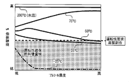
- the rate at which the fuel injection amount is increased to ensure the required torque can be calculated from the data shown in FIG. 3 based on the engine temperature (water temperature or oil temperature) and the alcohol concentration in the fuel. it can.
- FIG. 3 is a characteristic diagram showing the alcohol distillation rate at each water temperature and alcohol concentration. As shown in this figure, the alcohol distillation ratio calculated from the characteristic line in FIG.
- the required cylinder wall temperature Ty is preferably set as shown in FIG. 4 based on the alcohol concentration in the fuel.
- FIG. 4 is a characteristic diagram showing the relationship between the alcohol concentration in the fuel and the required cylinder wall temperature. Therefore, in the present embodiment, for example, the required cylinder wall temperature Ty is calculated based on the alcohol concentration in the fuel by referring to the data of FIG. 4 stored in advance in the ECU 60.
- the in-cylinder temperature Th during compression is a parameter corresponding to the gas temperature in the cylinder at the compression top dead center, and is estimated based on at least the alcohol concentration E1 in the fuel. More specifically, as shown in the following equation (1), the in-cylinder temperature Th at the time of compression is the combustion temperature due to the specific heat difference between the non-alcohol fuel estimated combustion temperature T0 before fuel cut and the non-alcohol fuel E0 and the fuel in use. It is calculated based on the decrease amount ⁇ T, the heat flow rate Qcw from the cylinder wall surface to the cooling water, and the specific heat difference ⁇ Cv due to the change in scavenging efficiency (residual gas ratio) due to the valve timing.
- the non-alcohol fuel E0 means gasoline or the like whose alcohol concentration is zero.
- the estimated non-alcohol fuel combustion temperature T0 before fuel cut represents the combustion temperature before the start of fuel cut when the non-alcohol fuel E0 is used.
- the input energy intake air amount Ga
- ignition timing water temperature Thw
- the combustion temperature decrease amount ⁇ T represents the difference in combustion temperature between when the non-alcohol fuel E0 is used and when the current alcohol fuel (alcohol concentration E1) is used.
- the combustion temperature decrease amount ⁇ T is calculated based on the difference (specific heat difference) between the specific heat of the non-alcohol fuel E0 and the specific heat of the alcohol component in the used fuel, and the alcohol concentration E1 in the fuel.
- the specific heat of the combustion gas for the calculation process of the combustion temperature decrease amount ⁇ T.
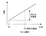
- the specific heat (gas component) of the combustion gas changes depending on the operating condition, so the combustion gas at each alcohol concentration It is difficult to specify the specific heat. Therefore, the combustion temperature decrease amount ⁇ T is calculated based on the specific heat difference between the specific heat of the non-alcohol fuel E0 and the specific heat of the alcohol component in the used fuel and the alcohol concentration E1 in the fuel with reference to FIG.
- FIG. 5 is a characteristic diagram showing the relationship between the alcohol concentration in the fuel and the specific heat.
- FIG. 6 is a PV characteristic diagram showing one cycle of the engine.
- t1 and t2 represent the in-cylinder temperature
- V1 and V2 represent the in-cylinder volume
- ⁇ represents the specific heat ratio.
- the in-cylinder temperature at the compression top dead center at the time of fuel cut can be obtained.
- the heat flow rate Qcw from the cylinder wall surface to the cooling water is calculated by calculating the heat transfer coefficient hg using an experimental formula such as the Woschni formula for heat transfer shown in the following formula (3). Ask for.
- hg 3.26D ⁇ 0.2 ⁇ P 0.8 ⁇ T ⁇ 0.53 ⁇ w 0.8 (3)
- hg spatial average instantaneous heat transfer coefficient (W / m 2 K)
- D Cylinder inner diameter (m)
- P Gas pressure (kPa)
- T Gas temperature (K)
- w Average piston speed (m / s)
- the specific heat difference ⁇ Cv due to the change in scavenging efficiency (residual gas ratio) due to the valve timing is calculated based on the residual gas ratio obtained from the valve timing before the start of fuel cut.
- the ECU 60 can estimate the in-cylinder temperature Th during compression based on the above parameters.
- FIG. 7 is a flowchart showing temperature balance control according to the first embodiment of the present invention.
- the routine shown in this figure is repeatedly executed during engine operation.
- IVO indicates the opening timing of the intake valve 32
- IVC indicates the closing timing of the intake valve 32
- EVO indicates the opening timing of the exhaust valve 34
- EVC indicates the closing timing of the exhaust valve 34.
- the IVO, IVC, EVO and EVC are controlled by the ECU 60 via the variable valve mechanisms 36 and 38.
- step 100 the alcohol concentration E1 in the fuel and the engine coolant water temperature Thw are detected.
- step 102 fuel cut is executed when an F / C request is generated due to engine deceleration or the like.
- step 104 as described above, the required cylinder wall temperature Ty and the in-cylinder temperature Th are calculated based on the alcohol concentration E1 in the fuel.
- step 106 it is determined whether or not the actual catalyst temperature Ts is lower than the activation decrease temperature T2. If this determination is established, in step 108, the water temperature Thw is higher than the required cylinder wall temperature Ty. It is determined whether or not. If both the determinations in steps 106 and 108 are established, the process proceeds to step 110 described below. If the determination in step 106 is not established, the process proceeds to step 130 described later. If the determination in step 108 is not established, the process proceeds to step 122 described later.
- step 110 when the actual catalyst temperature Ts is lower than the activity lowering temperature T2 and the water temperature Thw is higher than the required cylinder wall temperature Ty, the EVO is changed immediately after the compression top dead center (compression TDC) (catalyst). Control at low temperature / high temperature of cylinder).
- FIG. 8 is an explanatory diagram showing changes in the in-cylinder gas temperature when the catalyst low temperature / cylinder high temperature control is executed. In this case, since it is desired to prioritize the rise in the exhaust temperature over the maintenance of the cylinder wall temperature, the EVO is set immediately after the compression top dead center (the exhaust valve 34 is opened quickly). Thereby, the temperature of the exhaust gas supplied to the catalysts 24 and 25 can be raised, and the warm-up property of the catalyst can be improved.
- the control that makes EVO variable can obtain a remarkable effect when alcohol fuel is used. More specifically, alcohol fuel contains oxygen, so the laminar flame speed is high. As a result, when the alcohol concentration in the fuel is increased, the combustion speed is improved and the rise / fall time of the combustion temperature is shortened. Therefore, it is possible to cope with a change in the combustion speed by changing the EVO according to the alcohol concentration in the fuel. That is, for example, when it is desired to increase the exhaust temperature by reducing the cooling loss, or when the alcohol concentration in the fuel is high, it is possible to appropriately cope with the problem by increasing the EVO.
- the catalyst cryogenic temperature described below is further reduced. Time control may be executed. The determination as to whether or not Ts ⁇ T2 is established is realized based on whether or not the temperature difference between the actual catalyst temperature Ts and the activity decrease temperature T2 is larger than a predetermined large temperature difference determination value. Then, in the control at the catalyst cryogenic temperature, as shown in FIG. 8, IVC is set in the vicinity of the intake bottom dead center (early closing), and the actual compression ratio that changes according to the valve timing is increased. Thereby, the cylinder temperature Th at the time of compression can be raised, the exhaust gas temperature can be raised, and the warm-up property of the catalyst can be further improved.
- FIG. 9 is an explanatory diagram showing the contents of the operating angle expansion control. As shown in this figure, when the EVO is accelerated by the control at the catalyst low temperature and the cylinder high temperature, the EVC is also accelerated when the operating angle of the exhaust valve 34 is constant. In this case, a period (negative overlap) in which both the intake valve 32 and the exhaust valve 34 are closed occurs, the pump loss increases, and the drivability deteriorates.
- the operation angle of the exhaust valve is expanded to delay the EVC and to ensure a positive overlap period.
- the working angle of the intake valve can be expanded (adopting a variable working angle intake variable valve mechanism 36) and there is no fear of valve attack, the IVO is advanced by the advance amount of the EVO. Also good.
- step 116 it is determined in step 116 whether or not a return request from the fuel cut has occurred, and if this determination is satisfied, in step 118, The compression ratio, valve timing, throttle opening, etc. are changed to normal operation, and the fuel cut is canceled in step 120. On the other hand, if the determination in step 116 is not established, the process returns to step 106 to determine the actual catalyst temperature Ts.
- step 122 is performed. Then, it is determined whether or not the mechanical compression ratio is variable. If the compression ratio variable mechanism 40 is mounted, the determination in step 122 is established, and therefore, in step 124, equal Ga compression ratio increase control is executed. In the equal Ga compression ratio increase control, the mechanical compression ratio is increased by the compression ratio variable mechanism 40 while the intake air amount is kept constant by the throttle valve 22 or the like.
- the in-cylinder temperature Th can be increased by increasing the compression ratio, and the cylinder wall temperature can be increased by increasing the cooling loss. Further, the exhaust gas temperature is raised together with the in-cylinder gas temperature, and the warm-up performance of the catalysts 24 and 25 can be improved.
- step 126 control for changing EVO to timing when Th ⁇ Thw, that is, control for synchronizing EVO at timing when water temperature Thw and in-cylinder temperature Th become equal (cylinder wall temperature at low catalyst temperature).
- FIG. 10 is an explanatory diagram showing a change in the in-cylinder gas temperature when the cylinder wall temperature increase control is performed at a low catalyst temperature.
- the shaded area near the compression top dead center indicates the heat release area from the in-cylinder gas to the cylinder wall surface in the equal Ga compression ratio increase control
- the shaded area located near the conventional EVO represents the cylinder wall temperature.
- the cylinder wall surface ⁇ the endothermic region to the cylinder interior gas when the ascent control is not executed is shown.
- IVC may be set in the same manner as in the past.
- the cylinder wall temperature rise control when the catalyst temperature is low by synchronizing the EVO at the timing when the water temperature Thw and the in-cylinder temperature become equal, the endothermic amount from the cylinder wall surface to the in-cylinder gas is reduced. This can reduce the cylinder wall temperature.
- the alcohol concentration in the fuel is reflected in the compression cylinder temperature Th, when the alcohol concentration is high, the cylinder wall temperature can be increased, and the cylinder temperature can be increased according to the alcohol concentration. Wall temperature can be controlled appropriately.
- FIG. 11 is an explanatory diagram showing a change in in-cylinder gas temperature when IVC bottom dead center control is executed at a low catalyst temperature.
- the shaded area near the compression top dead center indicates the heat release area from the in-cylinder gas to the cylinder wall surface in IVC bottom dead center control, and the shaded area located near the conventional EVO indicates that the cylinder wall temperature rises. The endothermic region from cylinder wall surface to in-cylinder gas when control is not executed is shown.
- the actual compression ratio can be increased and the in-cylinder gas temperature can be increased. Thereby, the warm-up property of the catalyst and the cylinder wall temperature can be improved. Further, when the IVC bottom dead center control is executed, as shown in FIG. 11, the cylinder wall temperature rise control (step 126) at the time of low catalyst temperature may be executed. Thereby, cylinder wall temperature can be raised still more smoothly.
- IVC bottom dead center control can achieve a remarkable effect when using alcohol fuel. More specifically, when the alcohol fuel is burned, a large amount of water having a large specific heat is generated as compared to when gasoline is burned, so that the combustion temperature is lowered. Further, since alcohol has a large latent heat of vaporization and a small calorific value, for example, about 1.5 times as much fuel injection amount is required to maintain the same torque as gasoline. As a result, especially when high-concentration alcohol fuel is injected in the cold, a large amount of unburned fuel is mixed into the oil as the fuel injection amount increases, and at the compression top dead center at the time of fuel cut. The in-cylinder temperature decreases. For this reason, when using fuel with a high alcohol concentration, the compression end temperature, the actual compression ratio, and the in-cylinder temperature are increased by IVC bottom dead center control, thereby effectively suppressing a decrease in the combustion temperature (in-cylinder temperature). be able to.
- step 106 determines whether or not the catalyst deterioration temperature T1. If this determination is established, it is determined in step 132 whether or not the water temperature Thw is higher than the required cylinder wall temperature Ty. If the determination in step 132 is satisfied, that is, if the actual catalyst temperature Ts is higher than the catalyst deterioration temperature T1 and the water temperature Thw is higher than the required cylinder wall temperature Ty, in step 134, the catalyst temperature is high.
- the cylinder wall temperature rise control is executed. In this control, EVO is set at a timing at which the water temperature Thw becomes equal to the in-cylinder temperature.
- FIG. 12 is an explanatory diagram showing a change in the in-cylinder gas temperature when the cylinder wall temperature increase control is performed when the catalyst temperature is high.
- the hatched portion near the compression top dead center indicates the heat release area from the in-cylinder gas to the cylinder wall surface in the conventional control
- the mesh portion located in the vicinity of the conventional EVO is the cylinder in the EVO of the conventional control. The endothermic region from the wall surface to the in-cylinder gas is shown.
- step 140 it is determined in step 140 whether or not the mechanical compression ratio is variable. If the compression ratio variable mechanism 40 is mounted, the determination of step 140 is established, and therefore, an equal Ga compression ratio increase control is executed in step 142. In step 144, as in step 134, when the catalyst temperature is high. The cylinder wall temperature rise control is executed.
- FIG. 13 is an explanatory diagram showing changes in the in-cylinder gas temperature when the equal Ga compression ratio increase control and the cylinder wall temperature increase control at the high catalyst temperature are executed at the high catalyst temperature.
- step 142 when the actual catalyst temperature Ts is higher than the catalyst deterioration temperature T1 and the water temperature Thw is lower than the required cylinder wall temperature Ty, the mechanical compression ratio is set by the compression ratio variable mechanism 40. Increase the cylinder wall temperature and lower the exhaust temperature relatively.
- step 144 the EVO is synchronized with the timing at which the water temperature Thw becomes equal to the in-cylinder temperature. As a result, the cylinder wall temperature and the in-cylinder gas temperature can be raised as described above, and the exhaust gas temperature can be lowered relatively, and the catalysts 24 and 25 can be protected from deterioration.
- FIG. 14 is an explanatory diagram showing a change in in-cylinder gas temperature when IVC bottom dead center control is executed at a high catalyst temperature. That is, in step 146, when the actual catalyst temperature Ts is higher than the catalyst deterioration temperature T1 and the water temperature Thw is lower than the required cylinder wall temperature Ty, the IVC is set near the intake bottom dead center. According to this control, the actual compression ratio can be increased and the in-cylinder gas temperature can be increased. Thereby, the warm-up property of the catalyst and the cylinder wall temperature can be improved.
- step 116 it is determined in step 116 whether or not a return request from the fuel cut has occurred. If this determination is established, as described above, first, after returning to normal operation in step 118, the fuel cut is canceled in step 120.
- both the actual catalyst temperature Ts falls within the temperature range (T1 to T2) suitable for the operation of the catalysts 24 and 25, and the water temperature Thw becomes close to the required cylinder wall temperature Ty.
- T1 to T2 the temperature range
- step 104 in FIG. 7 shows a specific example of the required cylinder wall temperature calculating means in claim 1 and the in-cylinder temperature estimating means in claim 7, and steps 106 to 144 are claimed in claim 1.
- the specific example of the temperature balance control means in is shown.
- step 110 shows a specific example of the catalyst low temperature / cylinder high temperature control means in claim 3
- step 124 shows a specific example of the temperature raising means in claim 5
- step 126 shows the cylinder in claim 7.
- a concrete example of the wall temperature raising means is shown
- step 128 shows a concrete example of the temperature raising means in claim 6.
- step 134 shows a specific example of the exhaust gas temperature lowering priority means in claim 8
- step 142 shows a specific example of the temperature adjustment means in claim 9
- step 146 shows in-cylinder temperature increase in claim 10.
- a specific example of the means is shown.
- FIG. 8 shows a specific example of the control means at the catalyst cryogenic temperature in claim 4.
- the intake valve 32, the exhaust valve 34, the compression ratio variable mechanism 40, and the like are controlled.
- the present invention controls at least the valve opening characteristics of the exhaust valve 34, and it is not always necessary to control the intake valve 32 and the compression ratio variable mechanism 40.
- the water temperature Thw is exemplified as an example of the parameter corresponding to the cylinder wall temperature.
- the present invention is not limited to this, and an oil temperature or the like may be used as the cylinder wall temperature.
- the actual catalyst temperature Ts is detected by the catalyst temperature sensor 52 .
- the present invention is not limited to this.
- the actual catalyst temperature may be estimated based on a parameter reflecting the operating state of the engine without using the catalyst temperature sensor 52.
- the input energy can be calculated based on the integrated value (integrated intake air amount) of the intake air amount and the exhaust air-fuel ratio, and the catalyst temperature can be estimated based on the input energy.
- an estimated value of the catalyst temperature calculated in this way may be adopted.
Landscapes
- Engineering & Computer Science (AREA)
- Chemical & Material Sciences (AREA)
- Combustion & Propulsion (AREA)
- Mechanical Engineering (AREA)
- General Engineering & Computer Science (AREA)
- Oil, Petroleum & Natural Gas (AREA)
- Chemical Kinetics & Catalysis (AREA)
- Health & Medical Sciences (AREA)
- Toxicology (AREA)
- Output Control And Ontrol Of Special Type Engine (AREA)
- Electrical Control Of Air Or Fuel Supplied To Internal-Combustion Engine (AREA)
- Combined Controls Of Internal Combustion Engines (AREA)
Abstract
Description
尚、出願人は、本発明に関連するものとして、上記の文献を含めて、以下に記載する文献を認識している。
排気バルブの開弁特性を可変に設定する排気バルブタイミング可変機構と、
前記排気浄化触媒の温度を実触媒温度として検出または推定する触媒温度取得手段と、
前記排気浄化触媒の作動に適した触媒温度を目標触媒温度として設定する目標触媒温度設定手段と、
前記シリンダの壁面温度であるシリンダ壁温を検出するシリンダ壁温検出手段と、
燃料カットからの復帰時に必要とされるシリンダ壁温を要求シリンダ壁温として算出する要求シリンダ壁温算出手段と、
燃料カットが実行されるときに、前記実触媒温度と前記目標触媒温度との大小関係及び前記シリンダ壁温と前記要求シリンダ壁温との大小関係に基いて、前記排気バルブタイミング可変機構により前記排気バルブの開弁特性を制御する温度バランス制御手段と、
を備えることを特徴とする。
前記要求シリンダ壁温算出手段は、燃料中のアルコール濃度が高いほど、前記要求シリンダ壁温を高い温度に算出する構成としている。
前記温度バランス制御手段は、前記実触媒温度が前記活性低下温度よりも低く、かつ、前記シリンダ壁温が前記要求シリンダ壁温よりも高い場合に、前記排気バルブの開弁タイミングを圧縮上死点の直後に設定する触媒低温・シリンダ高温時制御手段を備える。
前記温度バランス制御手段は、前記実触媒温度と前記活性低下温度との温度差が所定の大温度差判定値よりも大きい場合に、前記吸気バルブタイミング可変機構により前記吸気バルブの閉弁タイミングを吸気下死点の近傍に設定する触媒極低温時制御手段を備える。
前記温度バランス制御手段は、前記実触媒温度が前記活性低下温度よりも低く、かつ、前記シリンダ壁温が前記要求シリンダ壁温よりも低い場合に、前記圧縮比可変機構により機械圧縮比を増加させ、前記シリンダ内のガス温度及び前記シリンダ壁温を上昇させる温度上昇手段を備える。
前記温度バランス制御手段は、前記排気バルブの開弁タイミングを、前記シリンダ壁温と前記筒内温度とが等しくなるタイミングに設定するシリンダ壁温上昇手段を備える。
前記温度バランス制御手段は、前記実触媒温度が前記触媒劣化温度以上となり、かつ、前記シリンダ壁温が前記要求シリンダ壁温よりも高い場合に、前記排気バルブの開弁タイミングを、前記シリンダ壁温と前記筒内温度とが等しくなるタイミングに設定する排気温度低下優先手段を備える。
前記温度バランス制御手段は、前記実触媒温度が前記触媒劣化温度以上となり、かつ、前記シリンダ壁温が前記要求シリンダ壁温よりも低い場合に、前記圧縮比可変機構により機械圧縮比を増加させ、前記シリンダ壁温を上昇させて排気温度を低下させる温度調整手段を備える。
前記温度バランス制御手段は、前記実触媒温度が前記触媒劣化温度以上となり、かつ、前記シリンダ壁温が前記要求シリンダ壁温よりも低い場合に、前記吸気バルブタイミング可変機構により前記吸気バルブの閉弁タイミングを吸気下死点の近傍に設定する筒内温度上昇手段を備える。
[実施の形態1の構成]
以下、図1乃至図14を参照して、本発明の実施の形態1について説明する。図1は、本発明の実施の形態1のシステム構成を説明するための構成図である。本実施の形態のシステムは、多気筒型の内燃機関としてのエンジン10を備えている。なお、図1では、エンジン10の1気筒のみを例示しているが、本発明は、単気筒を含む任意の気筒数のエンジンに適用されるものである。また、エンジン10は、例えばFFV(Flexible-Fuel Vehicle)等の車両に搭載されるもので、エタノール等を含むアルコール燃料が使用可能となっている。
本実施の形態では、燃料カットが実行されるときに、温度バランス制御を実行することを特徴としている。温度バランス制御は、実触媒温度Ts及びシリンダ壁温(本実施の形態では、水温Thw)が個々の目標の温度に近くなるように、両方の温度をバランス良く制御する。より具体的に述べると、温度バランス制御は、実触媒温度Tsと目標触媒温度(触媒劣化温度T1または活性低下温度T2)との大小関係、及び水温Thwと要求シリンダ壁温Tyとの大小関係に基いて、吸気バルブ32や排気バルブ34の開弁特性を制御するものである。温度バランス制御の具体的な処理については後述するものとし、まず、同制御で用いられる要求シリンダ壁温Tyと圧縮時筒内温度Thについて説明する。
要求シリンダ壁温Tyとは、燃料カットからの復帰時に必要とされるシリンダ壁温(水温Thw)の目標値に対応するものであり、後述の図4に示すように、少なくとも燃料中のアルコール濃度に基いて算出される。アルコール濃度に基いて要求シリンダ壁温Tyを算出するのは、以下の理由による。まず、要求シリンダ壁温Tyは、燃料カットからの復帰時に非アルコール燃料(ガソリン等)と同等の排気エミッションを実現することが可能なシリンダ壁温に相当している。アルコールは沸点が高くて気化し難いので、特に冷間始動時(シリンダ壁温が低い時)には、NMOGエミッション(排気ガス中に含まれる非メタン有機ガス、炭化水素等の合計量)が悪化し易い。この場合、シリンダ壁温が低いほど、噴射燃料がシリンダの壁面に付着して液膜を形成するので、排気エミッションが悪化する。このため、要求シリンダ壁温Tyは、燃料中のアルコール濃度に基いて算出され、図2に示すように、燃料中のアルコール濃度が高いほど、高い温度に設定される。
圧縮時筒内温度Thとは、圧縮上死点におけるシリンダ内のガス温度に対応するパラメータであり、少なくとも燃料中のアルコール濃度E1に基いて推定される。詳しく述べると、圧縮時筒内温度Thは、下記(1)式に示すように、燃料カット前非アルコール燃料推定燃焼温度T0と、非アルコール燃料E0と使用中の燃料との比熱差による燃焼温度低下量ΔTと、シリンダ壁面から冷却水への熱流量Qcwと、バルブタイミングに起因する掃気効率(残留ガス割合)の変化による比熱差ΔCvとに基いて算出される。なお、非アルコール燃料E0とは、アルコール濃度が零であるガソリン等を意味している。
但し、hg:空間平均瞬間熱伝達率(W/m2K)
D:シリンダ内径(m)
P:ガス圧力(kPa)
T:ガス温度(K)
w:ピストン平均速度(m/s)
次に、図7を参照して、温度バランス制御の具体的な処理について説明する。図7は、本発明の実施の形態1による温度バランス制御を示すフローチャートである。この図に示すルーチンは、エンジンの運転中に繰返し実行されるものである。また、以下の説明において、「IVO」は吸気バルブ32の開弁タイミングを示し、「IVC」は吸気バルブ32の閉弁タイミングを示し、「EVO」は排気バルブ34の開弁タイミングを示し、「EVC」は排気バルブ34の閉弁タイミングを示すものとする。上記IVO、IVC、EVO及びEVCは、ECU60により可変動弁機構36,38を介して制御される。
ステップ110では、実触媒温度Tsが活性低下温度T2よりも低く、かつ、水温Thwが要求シリンダ壁温Tyよりも高い場合に、EVOを圧縮上死点(圧縮TDC)の直後に変更する(触媒低温・シリンダ高温時制御)。図8は、触媒低温・シリンダ高温時制御を実行した場合の筒内ガス温度の変化を示す説明図である。この場合には、シリンダ壁温の維持よりも排気温度の上昇を優先したいので、EVOを圧縮上死点の直後に設定(排気バルブ34を早開き)する。これにより、触媒24,25に供給される排気ガスの温度を上昇させ、触媒の暖機性を向上させることができる。
ステップ106の判定が成立してステップ108の判定が不成立の場合、即ち、実触媒温度Tsが活性低下温度T2よりも低く、かつ、水温Thwが要求シリンダ壁温Ty以下の場合には、ステップ122に移行して機械圧縮比が可変であるか否かを判定する。圧縮比可変機構40が搭載されている場合には、ステップ122の判定が成立するので、ステップ124において、等Ga圧縮比増加制御を実行する。等Ga圧縮比増加制御は、スロットルバルブ22等により吸入空気量を一定に保持した状態で、圧縮比可変機構40により機械圧縮比を増加させるものである。この制御によれば、圧縮比の増加により圧縮時筒内温度Thを上昇させ、冷却損失の増大によりシリンダ壁温を高めることができる。また、筒内ガス温度と共に排気温度も上昇させ、触媒24,25の暖機性を向上させることができる。
一方、図7において、ステップ106の判定が不成立の場合には、ステップ130に移行し、実触媒温度Tsが触媒劣化温度T1よりも高いか否かを判定する。この判定が成立した場合には、ステップ132において、水温Thwが要求シリンダ壁温Tyよりも高いか否かを判定する。そして、ステップ132の判定が成立した場合、即ち、実触媒温度Tsが触媒劣化温度T1よりも高く、かつ、水温Thwが要求シリンダ壁温Tyよりも高い場合には、ステップ134において、触媒高温時のシリンダ壁温上昇制御を実行する。この制御では、水温Thwと筒内温度とが等しくなるタイミングにEVOを設定する。図12は、触媒高温時のシリンダ壁温上昇制御を実行した場合の筒内ガス温度の変化を示す説明図である。この図において、圧縮上死点近傍の斜線部は、従来制御での筒内ガス→シリンダ壁面への放熱域を示し、従来のEVOの近傍に位置する網線部は、従来制御のEVOにおけるシリンダ壁面→筒内ガスへの吸熱域を示している。
12 ピストン
14 燃焼室
16 クランク軸
18 吸気通路
20 排気通路
22 スロットルバルブ
24,26 触媒
28 燃料噴射弁
30 点火プラグ
32 吸気バルブ
34 排気バルブ
36 吸気可変動弁機構(吸気バルブタイミング可変機構)
38 排気可変動弁機構(排気バルブタイミング可変機構)
40 圧縮比可変機構
42 クランク角センサ
44 エアフローセンサ
46 水温センサ(シリンダ壁温検出手段)
48 メイン空燃比センサ
50 サブO2センサ
52 触媒温度センサ(触媒温度取得手段)
54 アルコール濃度センサ(アルコール濃度検出手段)
60 ECU(目標触媒温度設定手段)
Thw 水温(シリンダ壁温)
Ts 実触媒温度
T1 触媒劣化温度(目標触媒温度)
T2 活性低下温度(目標触媒温度)
Ty 要求シリンダ壁温
Th 圧縮時筒内温度(筒内温度)
Claims (10)
- 内燃機関のシリンダから排出される排気ガスを浄化する排気浄化触媒と、
排気バルブの開弁特性を可変に設定する排気バルブタイミング可変機構と、
前記排気浄化触媒の温度を実触媒温度として検出または推定する触媒温度取得手段と、
前記排気浄化触媒の作動に適した触媒温度を目標触媒温度として設定する目標触媒温度設定手段と、
前記シリンダの壁面温度であるシリンダ壁温を検出するシリンダ壁温検出手段と、
燃料カットからの復帰時に必要とされるシリンダ壁温を要求シリンダ壁温として算出する要求シリンダ壁温算出手段と、
燃料カットが実行されるときに、前記実触媒温度と前記目標触媒温度との大小関係及び前記シリンダ壁温と前記要求シリンダ壁温との大小関係に基いて、前記排気バルブタイミング可変機構により前記排気バルブの開弁特性を制御する温度バランス制御手段と、
を備えることを特徴とする内燃機関の制御装置。 - 燃料中のアルコール濃度を検出するアルコール濃度検出手段を備え、
前記要求シリンダ壁温算出手段は、燃料中のアルコール濃度が高いほど、前記要求シリンダ壁温を高い温度に算出する構成としてなる請求項1に記載の内燃機関の制御装置。 - 前記目標触媒温度は、前記排気浄化触媒が活性化する触媒温度範囲の下限値に対応する所定の活性低下温度を含む構成とし、
前記温度バランス制御手段は、前記実触媒温度が前記活性低下温度よりも低く、かつ、前記シリンダ壁温が前記要求シリンダ壁温よりも高い場合に、前記排気バルブの開弁タイミングを圧縮上死点の直後に設定する触媒低温・シリンダ高温時制御手段を備えてなる請求項1または2に記載の内燃機関の制御装置。 - 吸気バルブの開弁特性を可変に設定する吸気バルブタイミング可変機構を備え、
前記温度バランス制御手段は、前記実触媒温度と前記活性低下温度との温度差が所定の大温度差判定値よりも大きい場合に、前記吸気バルブタイミング可変機構により前記吸気バルブの閉弁タイミングを吸気下死点の近傍に設定する触媒極低温時制御手段を備えてなる請求項3に記載の内燃機関の制御装置。 - 前記シリンダの機械圧縮比を可変に設定することが可能な圧縮比可変機構を備え、
前記温度バランス制御手段は、前記実触媒温度が前記活性低下温度よりも低く、かつ、前記シリンダ壁温が前記要求シリンダ壁温よりも低い場合に、前記圧縮比可変機構により機械圧縮比を増加させ、前記シリンダ内のガス温度及び前記シリンダ壁温を上昇させる温度上昇手段を備えてなる請求項1乃至4のうち何れか1項に記載の内燃機関の制御装置。 - 前記温度バランス制御手段は、前記実触媒温度が前記活性低下温度よりも低く、かつ、前記シリンダ壁温が前記要求シリンダ壁温よりも低い場合に、前記吸気バルブの閉弁タイミングを吸気下死点の近傍に設定し、前記シリンダ内のガス温度及び前記シリンダ壁温を上昇させる温度上昇手段を備えてなる請求項1乃至4のうち何れか1項に記載の内燃機関の制御装置。
- 少なくとも燃料中のアルコール濃度に基いて、圧縮上死点における前記シリンダ内の温度である筒内温度を推定する筒内温度推定手段を備え、
前記温度バランス制御手段は、前記排気バルブの開弁タイミングを、前記シリンダ壁温と前記筒内温度とが等しくなるタイミングに設定するシリンダ壁温上昇手段を備えてなる請求項5または6に記載の内燃機関の制御装置。 - 前記目標触媒温度は、前記排気浄化触媒の劣化が進行する触媒温度範囲の下限値に対応する所定の触媒劣化温度を含む構成とし、
前記温度バランス制御手段は、前記実触媒温度が前記触媒劣化温度以上となり、かつ、前記シリンダ壁温が前記要求シリンダ壁温よりも高い場合に、前記排気バルブの開弁タイミングを、前記シリンダ壁温と前記筒内温度とが等しくなるタイミングに設定する排気温度低下優先手段を備えてなる請求項1乃至7のうち何れか1項に記載の内燃機関の制御装置。 - 前記シリンダの機械圧縮比を可変に設定することが可能な圧縮比可変機構を備え、
前記温度バランス制御手段は、前記実触媒温度が前記触媒劣化温度以上となり、かつ、前記シリンダ壁温が前記要求シリンダ壁温よりも低い場合に、前記圧縮比可変機構により機械圧縮比を増加させ、前記シリンダ壁温を上昇させて排気温度を低下させる温度調整手段を備えてなる請求項1乃至8のうち何れか1項に記載の内燃機関の制御装置。 - 吸気バルブの開弁特性を可変に設定する吸気バルブタイミング可変機構を備え、
前記温度バランス制御手段は、前記実触媒温度が前記触媒劣化温度以上となり、かつ、前記シリンダ壁温が前記要求シリンダ壁温よりも低い場合に、前記吸気バルブタイミング可変機構により前記吸気バルブの閉弁タイミングを吸気下死点の近傍に設定する筒内温度上昇手段を備えてなる請求項1乃至8のうち何れか1項に記載の内燃機関の制御装置。
Priority Applications (5)
| Application Number | Priority Date | Filing Date | Title |
|---|---|---|---|
| EP12871958.0A EP2829710B1 (en) | 2012-03-22 | 2012-03-22 | Control device for internal combustion engine |
| JP2014505905A JP5854126B2 (ja) | 2012-03-22 | 2012-03-22 | 内燃機関の制御装置 |
| US14/383,963 US9249740B2 (en) | 2012-03-22 | 2012-03-22 | Control device for internal combustion engine |
| CN201280071688.1A CN104204471B (zh) | 2012-03-22 | 2012-03-22 | 内燃机的控制装置 |
| PCT/JP2012/057357 WO2013140577A1 (ja) | 2012-03-22 | 2012-03-22 | 内燃機関の制御装置 |
Applications Claiming Priority (1)
| Application Number | Priority Date | Filing Date | Title |
|---|---|---|---|
| PCT/JP2012/057357 WO2013140577A1 (ja) | 2012-03-22 | 2012-03-22 | 内燃機関の制御装置 |
Publications (1)
| Publication Number | Publication Date |
|---|---|
| WO2013140577A1 true WO2013140577A1 (ja) | 2013-09-26 |
Family
ID=49222071
Family Applications (1)
| Application Number | Title | Priority Date | Filing Date |
|---|---|---|---|
| PCT/JP2012/057357 Ceased WO2013140577A1 (ja) | 2012-03-22 | 2012-03-22 | 内燃機関の制御装置 |
Country Status (5)
| Country | Link |
|---|---|
| US (1) | US9249740B2 (ja) |
| EP (1) | EP2829710B1 (ja) |
| JP (1) | JP5854126B2 (ja) |
| CN (1) | CN104204471B (ja) |
| WO (1) | WO2013140577A1 (ja) |
Cited By (1)
| Publication number | Priority date | Publication date | Assignee | Title |
|---|---|---|---|---|
| JP2014202153A (ja) * | 2013-04-08 | 2014-10-27 | マツダ株式会社 | 火花点火式エンジンの制御装置 |
Families Citing this family (18)
| Publication number | Priority date | Publication date | Assignee | Title |
|---|---|---|---|---|
| US9239018B2 (en) * | 2010-06-16 | 2016-01-19 | Toyota Jidosha Kabushiki Kaisha | Fuel control apparatus for internal combustion engine |
| JP5880708B2 (ja) * | 2012-06-25 | 2016-03-09 | トヨタ自動車株式会社 | 内燃機関の制御装置 |
| WO2016166859A1 (ja) * | 2015-04-16 | 2016-10-20 | 日産自動車株式会社 | エンジン制御装置及びエンジン制御方法 |
| JP6217724B2 (ja) * | 2015-09-24 | 2017-10-25 | トヨタ自動車株式会社 | 内燃機関の制御装置 |
| US10563549B2 (en) | 2015-09-25 | 2020-02-18 | Eaton Intelligent Power Limited | Cylinder deactivation control and methods |
| JP6296045B2 (ja) * | 2015-12-08 | 2018-03-20 | トヨタ自動車株式会社 | 内燃機関の制御装置 |
| CN108431390B (zh) * | 2016-01-19 | 2022-03-18 | 伊顿智能动力有限公司 | 针对热管理的汽缸停用和发动机制动 |
| JP6697374B2 (ja) | 2016-12-19 | 2020-05-20 | 日立オートモティブシステムズ株式会社 | 内燃機関の制御装置及び燃焼室壁温推定方法 |
| GB2560872B (en) * | 2016-12-23 | 2020-03-18 | Ricardo Uk Ltd | Split cycle engine |
| WO2018203360A1 (ja) * | 2017-05-01 | 2018-11-08 | 日産自動車株式会社 | 内燃機関の制御方法及び内燃機関の制御装置 |
| DE102017219172A1 (de) | 2017-10-25 | 2019-04-25 | Bayerische Motoren Werke Aktiengesellschaft | Steuereinrichtung zum Ansteuern eines Verbrennungsmotors und Verfahren zum Erwärmen einer Abgasreinigungseinrichtung |
| US10156219B1 (en) * | 2017-11-27 | 2018-12-18 | GM Global Technology Operations LLC | Method for controlling spark timing in a cold start condition for an engine in a vehicle propulsion system and controller for executing the method |
| JP7348715B2 (ja) * | 2018-04-26 | 2023-09-21 | 株式会社三井E&S Du | エンジンシステム |
| US20220001851A1 (en) * | 2018-11-06 | 2022-01-06 | Hitachi Astemo, Ltd. | Internal Combustion Engine Control Device |
| CA3140048A1 (en) | 2019-05-15 | 2020-11-19 | Clearflame Engines, Inc. | Cold-start for high-octane fuels in a diesel engine architecture |
| JP2023516273A (ja) | 2020-02-26 | 2023-04-19 | クリアフレーム エンジンズ,インコーポレイテッド | 燃料に依存しない圧縮着火エンジン |
| BR112023000330A2 (pt) | 2020-07-09 | 2023-03-28 | Clearflame Engines Inc | Sistemas e métodos de desativação de cilindro em motores com controle de mistura em alta temperatura |
| CN116255266A (zh) * | 2023-04-25 | 2023-06-13 | 浙江吉利控股集团有限公司 | 甲醇发动机控制方法、电子设备及存储介质 |
Citations (11)
| Publication number | Priority date | Publication date | Assignee | Title |
|---|---|---|---|---|
| JP2000087769A (ja) | 1998-09-09 | 2000-03-28 | Toyota Motor Corp | 内燃機関のバルブ特性制御装置 |
| JP2001164970A (ja) * | 1999-12-06 | 2001-06-19 | Toyota Motor Corp | 車両の燃料供給停止時の制御装置 |
| JP2006097602A (ja) | 2004-09-30 | 2006-04-13 | Toyota Motor Corp | 可変動弁機構 |
| JP2006342680A (ja) | 2005-06-07 | 2006-12-21 | Toyota Motor Corp | 内燃機関の冷却装置 |
| JP2007016710A (ja) | 2005-07-08 | 2007-01-25 | Hitachi Ltd | 内燃機関の動弁制御システム |
| JP2007132326A (ja) | 2005-11-14 | 2007-05-31 | Toyota Motor Corp | 内燃機関の制御装置 |
| JP2008261350A (ja) * | 2008-08-07 | 2008-10-30 | Toyota Motor Corp | 可変動弁機構を有する内燃機関 |
| JP2009079517A (ja) | 2007-09-26 | 2009-04-16 | Toyota Motor Corp | 内燃機関の制御装置 |
| JP2010127260A (ja) * | 2008-12-01 | 2010-06-10 | Toyota Motor Corp | 内燃機関の制御装置 |
| JP2010196650A (ja) * | 2009-02-26 | 2010-09-09 | Toyota Motor Corp | 内燃機関の可変気筒制御装置 |
| JP2012007591A (ja) | 2010-06-28 | 2012-01-12 | Toyota Motor Corp | 圧縮比可変機構を備える内燃機関の制御装置 |
Family Cites Families (12)
| Publication number | Priority date | Publication date | Assignee | Title |
|---|---|---|---|---|
| US5813383A (en) * | 1996-09-04 | 1998-09-29 | Cummings; Henry W. | Variable displacement diesel engine |
| JP3325230B2 (ja) * | 1998-08-03 | 2002-09-17 | マツダ株式会社 | 筒内噴射式エンジンの触媒暖機方法及び同装置 |
| JP2001289093A (ja) * | 2000-03-31 | 2001-10-19 | Hitachi Ltd | 筒内噴射エンジンの排気制御装置 |
| JP3680217B2 (ja) * | 2000-06-26 | 2005-08-10 | トヨタ自動車株式会社 | 内燃機関の空燃比制御装置 |
| EP1457653B1 (en) * | 2003-03-11 | 2009-04-15 | Nissan Motor Co., Ltd. | Engine fuel injection control |
| US6990968B2 (en) * | 2003-07-24 | 2006-01-31 | Nissan Motor Co., Ltd. | Engine fuel injection amount control device |
| JP4367398B2 (ja) * | 2005-10-19 | 2009-11-18 | トヨタ自動車株式会社 | 内燃機関の制御装置 |
| JP5145789B2 (ja) * | 2007-06-22 | 2013-02-20 | スズキ株式会社 | 内燃機関の可変バルブタイミング制御装置 |
| JP2009185658A (ja) * | 2008-02-05 | 2009-08-20 | Hitachi Ltd | 多気筒内燃機関の排気処理装置 |
| DE102008036635B4 (de) * | 2008-08-06 | 2018-10-04 | Continental Automotive Gmbh | Verfahren und Vorrichtung zum Steuern einer Brennkraftmaschine mit variablem Ventiltrieb und einem steuerbaren Ladeluftkühler |
| JP4725653B2 (ja) * | 2009-01-30 | 2011-07-13 | トヨタ自動車株式会社 | 多気筒内燃機関の運転制御装置 |
| WO2011158326A1 (ja) * | 2010-06-15 | 2011-12-22 | トヨタ自動車株式会社 | 内燃機関の制御装置 |
-
2012
- 2012-03-22 EP EP12871958.0A patent/EP2829710B1/en not_active Not-in-force
- 2012-03-22 JP JP2014505905A patent/JP5854126B2/ja not_active Expired - Fee Related
- 2012-03-22 CN CN201280071688.1A patent/CN104204471B/zh not_active Expired - Fee Related
- 2012-03-22 US US14/383,963 patent/US9249740B2/en not_active Expired - Fee Related
- 2012-03-22 WO PCT/JP2012/057357 patent/WO2013140577A1/ja not_active Ceased
Patent Citations (11)
| Publication number | Priority date | Publication date | Assignee | Title |
|---|---|---|---|---|
| JP2000087769A (ja) | 1998-09-09 | 2000-03-28 | Toyota Motor Corp | 内燃機関のバルブ特性制御装置 |
| JP2001164970A (ja) * | 1999-12-06 | 2001-06-19 | Toyota Motor Corp | 車両の燃料供給停止時の制御装置 |
| JP2006097602A (ja) | 2004-09-30 | 2006-04-13 | Toyota Motor Corp | 可変動弁機構 |
| JP2006342680A (ja) | 2005-06-07 | 2006-12-21 | Toyota Motor Corp | 内燃機関の冷却装置 |
| JP2007016710A (ja) | 2005-07-08 | 2007-01-25 | Hitachi Ltd | 内燃機関の動弁制御システム |
| JP2007132326A (ja) | 2005-11-14 | 2007-05-31 | Toyota Motor Corp | 内燃機関の制御装置 |
| JP2009079517A (ja) | 2007-09-26 | 2009-04-16 | Toyota Motor Corp | 内燃機関の制御装置 |
| JP2008261350A (ja) * | 2008-08-07 | 2008-10-30 | Toyota Motor Corp | 可変動弁機構を有する内燃機関 |
| JP2010127260A (ja) * | 2008-12-01 | 2010-06-10 | Toyota Motor Corp | 内燃機関の制御装置 |
| JP2010196650A (ja) * | 2009-02-26 | 2010-09-09 | Toyota Motor Corp | 内燃機関の可変気筒制御装置 |
| JP2012007591A (ja) | 2010-06-28 | 2012-01-12 | Toyota Motor Corp | 圧縮比可変機構を備える内燃機関の制御装置 |
Non-Patent Citations (1)
| Title |
|---|
| See also references of EP2829710A4 |
Cited By (1)
| Publication number | Priority date | Publication date | Assignee | Title |
|---|---|---|---|---|
| JP2014202153A (ja) * | 2013-04-08 | 2014-10-27 | マツダ株式会社 | 火花点火式エンジンの制御装置 |
Also Published As
| Publication number | Publication date |
|---|---|
| EP2829710A4 (en) | 2015-12-16 |
| US9249740B2 (en) | 2016-02-02 |
| JP5854126B2 (ja) | 2016-02-09 |
| EP2829710B1 (en) | 2016-11-30 |
| CN104204471A (zh) | 2014-12-10 |
| JPWO2013140577A1 (ja) | 2015-08-03 |
| CN104204471B (zh) | 2016-11-23 |
| EP2829710A1 (en) | 2015-01-28 |
| US20150152793A1 (en) | 2015-06-04 |
Similar Documents
| Publication | Publication Date | Title |
|---|---|---|
| JP5854126B2 (ja) | 内燃機関の制御装置 | |
| US9624855B2 (en) | Catalyst heating with exhaust back-pressure | |
| US8997457B2 (en) | Catalyst heating with exhaust back-pressure | |
| JP2008069785A (ja) | エンジン・システム及びエンジンの制御方法 | |
| JP6094599B2 (ja) | 内燃機関の制御装置および制御方法 | |
| US20150218999A1 (en) | Methods and systems for an exhaust gas treatment system | |
| US8868319B2 (en) | System and method for controlling intake valve timing in homogeneous charge compression ignition engines | |
| US20150337744A1 (en) | Control device for internal combustion engine | |
| JP2009191649A (ja) | 内燃機関の制御装置 | |
| JP6421802B2 (ja) | エンジンの制御装置 | |
| JP5364636B2 (ja) | 内燃機関の制御装置 | |
| JP4998400B2 (ja) | 内燃機関の始動制御装置 | |
| JP2013011176A (ja) | 内燃機関の制御装置 | |
| JP2018044480A (ja) | 可変動弁装置及び可変動弁装置のコントローラ | |
| JP4353252B2 (ja) | 内燃機関の制御システム | |
| JP5303349B2 (ja) | 内燃機関のegr制御装置 | |
| JP2007032415A (ja) | エンジンのバルブタイミング制御装置 | |
| JP2010024970A (ja) | 駆動力制御装置 | |
| JP2010270708A (ja) | 内燃機関の制御装置 | |
| US11739708B2 (en) | Methods for transient fuel control compensation | |
| JP2014066221A (ja) | 筒内噴射エンジンの制御装置 | |
| JP2011144721A (ja) | 内燃機関の点火時期制御装置 | |
| JP4359272B2 (ja) | 圧縮着火内燃機関の制御装置 | |
| CN105121820A (zh) | 用于内燃发动机的控制装置 | |
| JP2008202570A (ja) | 内燃機関の制御システム |
Legal Events
| Date | Code | Title | Description |
|---|---|---|---|
| 121 | Ep: the epo has been informed by wipo that ep was designated in this application |
Ref document number: 12871958 Country of ref document: EP Kind code of ref document: A1 |
|
| REEP | Request for entry into the european phase |
Ref document number: 2012871958 Country of ref document: EP |
|
| WWE | Wipo information: entry into national phase |
Ref document number: 2012871958 Country of ref document: EP |
|
| ENP | Entry into the national phase |
Ref document number: 2014505905 Country of ref document: JP Kind code of ref document: A |
|
| NENP | Non-entry into the national phase |
Ref country code: DE |
|
| WWE | Wipo information: entry into national phase |
Ref document number: 14383963 Country of ref document: US |