WO2013140747A1 - レーダ装置 - Google Patents
レーダ装置 Download PDFInfo
- Publication number
- WO2013140747A1 WO2013140747A1 PCT/JP2013/001621 JP2013001621W WO2013140747A1 WO 2013140747 A1 WO2013140747 A1 WO 2013140747A1 JP 2013001621 W JP2013001621 W JP 2013001621W WO 2013140747 A1 WO2013140747 A1 WO 2013140747A1
- Authority
- WO
- WIPO (PCT)
- Prior art keywords
- vehicle
- unit
- radar
- template
- output
- Prior art date
- Legal status (The legal status is an assumption and is not a legal conclusion. Google has not performed a legal analysis and makes no representation as to the accuracy of the status listed.)
- Ceased
Links
Images


Classifications
-
- G—PHYSICS
- G01—MEASURING; TESTING
- G01S—RADIO DIRECTION-FINDING; RADIO NAVIGATION; DETERMINING DISTANCE OR VELOCITY BY USE OF RADIO WAVES; LOCATING OR PRESENCE-DETECTING BY USE OF THE REFLECTION OR RERADIATION OF RADIO WAVES; ANALOGOUS ARRANGEMENTS USING OTHER WAVES
- G01S7/00—Details of systems according to groups G01S13/00, G01S15/00, G01S17/00
- G01S7/02—Details of systems according to groups G01S13/00, G01S15/00, G01S17/00 of systems according to group G01S13/00
- G01S7/41—Details of systems according to groups G01S13/00, G01S15/00, G01S17/00 of systems according to group G01S13/00 using analysis of echo signal for target characterisation; Target signature; Target cross-section
- G01S7/411—Identification of targets based on measurements of radar reflectivity
-
- G—PHYSICS
- G01—MEASURING; TESTING
- G01S—RADIO DIRECTION-FINDING; RADIO NAVIGATION; DETERMINING DISTANCE OR VELOCITY BY USE OF RADIO WAVES; LOCATING OR PRESENCE-DETECTING BY USE OF THE REFLECTION OR RERADIATION OF RADIO WAVES; ANALOGOUS ARRANGEMENTS USING OTHER WAVES
- G01S13/00—Systems using the reflection or reradiation of radio waves, e.g. radar systems; Analogous systems using reflection or reradiation of waves whose nature or wavelength is irrelevant or unspecified
- G01S13/02—Systems using reflection of radio waves, e.g. primary radar systems; Analogous systems
- G01S13/06—Systems determining position data of a target
- G01S13/08—Systems for measuring distance only
- G01S13/10—Systems for measuring distance only using transmission of interrupted, pulse modulated waves
- G01S13/26—Systems for measuring distance only using transmission of interrupted, pulse modulated waves wherein the transmitted pulses use a frequency- or phase-modulated carrier wave
- G01S13/28—Systems for measuring distance only using transmission of interrupted, pulse modulated waves wherein the transmitted pulses use a frequency- or phase-modulated carrier wave with time compression of received pulses
- G01S13/284—Systems for measuring distance only using transmission of interrupted, pulse modulated waves wherein the transmitted pulses use a frequency- or phase-modulated carrier wave with time compression of received pulses using coded pulses
-
- G—PHYSICS
- G01—MEASURING; TESTING
- G01S—RADIO DIRECTION-FINDING; RADIO NAVIGATION; DETERMINING DISTANCE OR VELOCITY BY USE OF RADIO WAVES; LOCATING OR PRESENCE-DETECTING BY USE OF THE REFLECTION OR RERADIATION OF RADIO WAVES; ANALOGOUS ARRANGEMENTS USING OTHER WAVES
- G01S13/00—Systems using the reflection or reradiation of radio waves, e.g. radar systems; Analogous systems using reflection or reradiation of waves whose nature or wavelength is irrelevant or unspecified
- G01S13/02—Systems using reflection of radio waves, e.g. primary radar systems; Analogous systems
- G01S13/50—Systems of measurement based on relative movement of target
- G01S13/58—Velocity or trajectory determination systems; Sense-of-movement determination systems
- G01S13/581—Velocity or trajectory determination systems; Sense-of-movement determination systems using transmission of interrupted pulse modulated waves and based upon the Doppler effect resulting from movement of targets
-
- G—PHYSICS
- G01—MEASURING; TESTING
- G01S—RADIO DIRECTION-FINDING; RADIO NAVIGATION; DETERMINING DISTANCE OR VELOCITY BY USE OF RADIO WAVES; LOCATING OR PRESENCE-DETECTING BY USE OF THE REFLECTION OR RERADIATION OF RADIO WAVES; ANALOGOUS ARRANGEMENTS USING OTHER WAVES
- G01S13/00—Systems using the reflection or reradiation of radio waves, e.g. radar systems; Analogous systems using reflection or reradiation of waves whose nature or wavelength is irrelevant or unspecified
- G01S13/88—Radar or analogous systems specially adapted for specific applications
- G01S13/91—Radar or analogous systems specially adapted for specific applications for traffic control
- G01S13/92—Radar or analogous systems specially adapted for specific applications for traffic control for velocity measurement
-
- G—PHYSICS
- G01—MEASURING; TESTING
- G01S—RADIO DIRECTION-FINDING; RADIO NAVIGATION; DETERMINING DISTANCE OR VELOCITY BY USE OF RADIO WAVES; LOCATING OR PRESENCE-DETECTING BY USE OF THE REFLECTION OR RERADIATION OF RADIO WAVES; ANALOGOUS ARRANGEMENTS USING OTHER WAVES
- G01S7/00—Details of systems according to groups G01S13/00, G01S15/00, G01S17/00
- G01S7/02—Details of systems according to groups G01S13/00, G01S15/00, G01S17/00 of systems according to group G01S13/00
- G01S7/41—Details of systems according to groups G01S13/00, G01S15/00, G01S17/00 of systems according to group G01S13/00 using analysis of echo signal for target characterisation; Target signature; Target cross-section
-
- G—PHYSICS
- G08—SIGNALLING
- G08G—TRAFFIC CONTROL SYSTEMS
- G08G1/00—Traffic control systems for road vehicles
- G08G1/01—Detecting movement of traffic to be counted or controlled
- G08G1/015—Detecting movement of traffic to be counted or controlled with provision for distinguishing between two or more types of vehicles, e.g. between motor-cars and cycles
-
- G—PHYSICS
- G08—SIGNALLING
- G08G—TRAFFIC CONTROL SYSTEMS
- G08G1/00—Traffic control systems for road vehicles
- G08G1/01—Detecting movement of traffic to be counted or controlled
- G08G1/052—Detecting movement of traffic to be counted or controlled with provision for determining speed or overspeed
-
- G—PHYSICS
- G01—MEASURING; TESTING
- G01S—RADIO DIRECTION-FINDING; RADIO NAVIGATION; DETERMINING DISTANCE OR VELOCITY BY USE OF RADIO WAVES; LOCATING OR PRESENCE-DETECTING BY USE OF THE REFLECTION OR RERADIATION OF RADIO WAVES; ANALOGOUS ARRANGEMENTS USING OTHER WAVES
- G01S13/00—Systems using the reflection or reradiation of radio waves, e.g. radar systems; Analogous systems using reflection or reradiation of waves whose nature or wavelength is irrelevant or unspecified
- G01S13/003—Bistatic radar systems; Multistatic radar systems
-
- G—PHYSICS
- G01—MEASURING; TESTING
- G01S—RADIO DIRECTION-FINDING; RADIO NAVIGATION; DETERMINING DISTANCE OR VELOCITY BY USE OF RADIO WAVES; LOCATING OR PRESENCE-DETECTING BY USE OF THE REFLECTION OR RERADIATION OF RADIO WAVES; ANALOGOUS ARRANGEMENTS USING OTHER WAVES
- G01S13/00—Systems using the reflection or reradiation of radio waves, e.g. radar systems; Analogous systems using reflection or reradiation of waves whose nature or wavelength is irrelevant or unspecified
- G01S13/87—Combinations of radar systems, e.g. primary radar and secondary radar
- G01S13/878—Combination of several spaced transmitters or receivers of known location for determining the position of a transponder or a reflector
-
- G—PHYSICS
- G01—MEASURING; TESTING
- G01S—RADIO DIRECTION-FINDING; RADIO NAVIGATION; DETERMINING DISTANCE OR VELOCITY BY USE OF RADIO WAVES; LOCATING OR PRESENCE-DETECTING BY USE OF THE REFLECTION OR RERADIATION OF RADIO WAVES; ANALOGOUS ARRANGEMENTS USING OTHER WAVES
- G01S7/00—Details of systems according to groups G01S13/00, G01S15/00, G01S17/00
- G01S7/02—Details of systems according to groups G01S13/00, G01S15/00, G01S17/00 of systems according to group G01S13/00
- G01S7/40—Means for monitoring or calibrating
- G01S7/4052—Means for monitoring or calibrating by simulation of echoes
- G01S7/4082—Means for monitoring or calibrating by simulation of echoes using externally generated reference signals, e.g. via remote reflector or transponder
- G01S7/4091—Means for monitoring or calibrating by simulation of echoes using externally generated reference signals, e.g. via remote reflector or transponder during normal radar operation
Definitions
- the present disclosure relates to a radar device that determines the traveling speed or vehicle type of a vehicle.
- the vehicle sensor is provided, for example, on the road or at the top of a column beside the road, and determines the traveling speed of the vehicle passing through the vehicle traveling lane directly below the vehicle sensor or the type of the vehicle.
- application of a radar device using microwaves or millimeter waves to a vehicle sensor has been considered.
- the present disclosure has been made in view of the above-described conventional circumstances, and an object of the present disclosure is to provide a radar device that improves the accuracy of vehicle type identification regardless of the shape of the vehicle, even with one radar device. .
- the present disclosure is a radar device installed at a predetermined height from a road surface, and a high-frequency radar transmission signal from a transmitting antenna tilted in a predetermined depression direction from the road at the predetermined height.
- Transmitter for transmitting toward the vehicle and radar receiver for estimating position parameters and vehicle speed of the vehicle traveling on the road using the reflected wave signal which is the radar transmission signal reflected by the vehicle traveling on the road
- the radar reception unit includes a correlation operation unit that performs correlation operation based on the reflected wave signal and the transmission code of the radar transmission signal, the N according to position parameters of the vehicle and the vehicle speed.
- a template generation unit that generates, as N templates, variation amounts of phase components in the reflected wave signal, any of the generated N templates, and the reflected wave signal N templates generated based on outputs of N template correlation operation units that perform correlation operation based on correlation values with the transmission code of the radar transmission signal, and N template correlation operation units
- an output selection unit that determines a vehicle type based on a position parameter of the vehicle and a vehicle speed according to any one of the templates.
- FIG. 1 A schematic view showing the arrangement of the radar device according to the first embodiment on the YZ plane, and (b) a schematic view showing the arrangement of the radar device according to the first embodiment on the XZ plane
- Block diagram schematically showing the internal configuration of the radar device of the first embodiment Block diagram showing in detail the internal configuration of the radar device of the first embodiment Diagram showing the relationship between the transmission interval Tw of the radar transmission signal and the transmission period Tr
- FIG. 1 A) Graph showing change in path difference at antenna height 5 m, vehicle height 3 m, frequency 60 GHz
- (b) Graph showing change in phase component at antenna height 5 m, vehicle height 3 m, frequency 60 GHz Graph showing change of real component of phase of template for each vehicle speed at antenna height 5m, same vehicle height 3m, frequency 60GHz, (a) when vehicle speed is 30km /
- Block diagram simply showing the internal configuration of the radar device of the sixth embodiment Block diagram showing in detail the internal configuration of the radar device of the sixth embodiment Configuration diagram of a conventional vehicle measurement system embodiment
- a schematic diagram showing the relationship between the measurement speed of the conventional millimeter wave radar and the vehicle speed in the road coordinate system (A) Doppler signal detection band diagram of the conventional radar device, (b) Doppler signal speed information diagram of the conventional radar device
- FIG. 19 is a block diagram of an embodiment of a conventional vehicle measurement system shown in Patent Document 1.
- a plurality of (for example, two) radar units 10a and 10b are used.
- the radar units 10a and 10b emit radio waves 16a and 16b from the antennas 11a and 11b toward the reference surface 5ba, and receive the radio waves 18a and 18b reflected from the reference surface 5ba or the vehicle 2TR.
- the radar units 10a and 10b calculate the time for the vehicle 2TR to pass the distance R between the two radar units 10a and 10b from the radio waves 18a and 18b, and further calculate the vehicle length and the vehicle speed based on the passing time. Do.
- FIG. 20 is a schematic view showing the relationship between the measurement speed of the conventional millimeter wave radar shown in Non-Patent Document 1 and the vehicle speed in the road coordinate system.
- the millimeter wave radar emits radio waves from the upper part of the pole provided on the roadside toward the road obliquely downward, and receives the reflected waves from the road surface and road structure within the detection beam width of the radio wave. Do.
- the millimeter wave radar receives the reflected wave from the vehicle and calculates the distance r (t), r (t + ⁇ t) between the millimeter wave radar and the vehicle at time t, (t + ⁇ t) And calculate the traveling speed of the vehicle. Furthermore, the millimeter wave radar calculates the relative velocity v based on the distances r (t), r (t + ⁇ t) and the time interval ⁇ t, calculates the vehicle length of the vehicle from the relative speed v and the time interval ⁇ t, Determine the type of car.
- FIG. 21 (a) is a Doppler signal detection band diagram of the conventional radar device shown in Patent Document 2
- FIG. 21 (b) is a Doppler signal speed information diagram of the conventional radar device.
- the radar device emits radio waves from the upper part of the support provided on the roadside toward the road obliquely downward.
- the velocity information of the Doppler signal obtained as the vehicle travels decreases as the vehicle approaches the antenna of the radar device, reaches a minimum value immediately under the antenna, and rises when passing under the antenna .
- the radar apparatus detects the vehicle speed v 1 based on the change in the velocity information of the Doppler signal when the angle ⁇ between the traveling direction of the vehicle and the straight line connecting the set position of the antenna and the reflection point of the radio wave is small. Based on the vehicle type signal (time T) in which the speed component v, which changes as it passes, v ⁇ v 1 (0 ⁇ ⁇ 1), v 1 T is calculated. Thus, the radar device can determine the vehicle type and the vehicle length of the vehicle.
- the radar device detects a vehicle based on the reflected wave signal reflected at the front end of the vehicle, and further determines the type of the vehicle. Therefore, depending on the shape of the vehicle, the reception level of the reflected wave signal at the front end of the vehicle front may be small.
- the radar apparatus detects a reflected wave signal in the middle of the vehicle as a reflected wave signal from the front end of the vehicle, an error occurs in the measurement of the vehicle length. For this reason, the vehicle type determination accuracy in the radar device may be degraded.
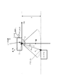
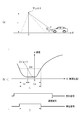
- FIG. 1 (a) is a schematic view showing the arrangement of the radar device 1 in the first embodiment on the YZ plane
- FIG. 1 (b) is the arrangement of the radar device 1 in the first embodiment on the XZ plane.
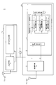
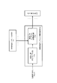
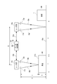
- FIG. 2 is a block diagram schematically showing the internal configuration of the radar device 1 of the first embodiment
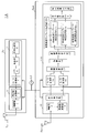
- FIG. 3 is a block diagram showing the internal configuration of the radar device 1 of the first embodiment in detail.
- FIG. 4 is a diagram showing the relationship between the transmission interval Tw of the radar transmission signal and the transmission period Tr.
- FIG. 5 is a block diagram showing an internal configuration of a modification of the transmission signal generation unit 2.
- the traveling direction of the vehicle TK to be detected by the radar device 1 is taken as the positive direction of the Y axis
- the direction perpendicular to the road surface GND is taken as the positive direction of the Z axis
- perpendicular to the YZ plane is taken as the positive direction of the Z axis
- the X axis is an axis
- the position on the XY plane directly below the radar device 1 is an origin O.
- a vehicle TK having a vehicle height z travels in the + Y-axis direction at a vehicle speed v.
- the radar device 1 is also inclined in the direction of a predetermined depression angle ⁇ on the ZY plane. In the present embodiment, the depression angle ⁇ of the radar device 1 is 90 ° (see FIG. 1A).
- the angle between the direction toward the road surface immediately below the radar device 1 and the direction of the path to the vehicle TK of the vehicle height z of the radar transmission signal transmitted from the radar device It is referred to as the prospect angle ⁇ (z) (see FIG. 1 (b)).
- the included angle ⁇ (z) in the XZ plane is ⁇ / 2 ⁇ (z).
- the radar device 1 transmits a radar transmission signal generated by the radar transmission unit Tx from the transmission antenna Tx-ant, and receives a reflected wave signal in which the radar transmission signal is reflected by the vehicle TK at the reception antenna Rx-Ant.
- the radar device 1 performs signal processing on the received reflected wave signal to estimate the vehicle height z and the vehicle speed v of the vehicle TK.
- the vehicle TK is illustrated as a detection target of the radar device 1.
- the detection target is not limited to the vehicle TK, and may be, for example, a person.
- the radar device 1 shown in FIG. 2 is configured to include a reference signal oscillator Lo, a radar transmitter Tx, and a radar receiver Rx.
- the radar transmission unit Tx is configured to include the transmission signal generation unit 2 and the transmission RF unit 3 to which the transmission antenna Tx-ant is connected.
- the reference signal oscillator Lo is connected to the radar transmitter Tx and the radar receiver Rx, and supplies a signal from the reference signal oscillator Lo to the radar transmitter Tx and the radar receiver Rx in common, thereby enabling the radar transmitter Tx and the radar.
- the processing of the receiving unit Rx is synchronized.
- the radar reception unit Rx has a reception RF unit 10 to which the reception antenna Rx-ant is connected, and a signal processing unit 11.
- the transmission signal generation unit 2 shown in FIG. 3 includes a code generation unit 4, a modulation unit 5, an LPF (Low Pass Filter) 6, and a D / A conversion unit 7.
- the LPF 6 may be provided outside the transmission signal generation unit 2, and the output of the LPF 6 is input to the D / A conversion unit 7.
- the transmission RF unit 3 shown in FIG. 3 includes a frequency converter 8 and an amplifier 9.
- the transmission signal generation unit 2 generates a transmission reference clock signal obtained by multiplying the reference signal by a predetermined factor based on the reference signal generated by the reference signal oscillator Lo. Each unit of the transmission signal generation unit 2 operates based on the generated transmission reference clock signal.
- the transmission signal generation unit 2 periodically generates the transmission signal r (k, M) of the baseband shown in Expression (1) by modulating the code sequence C n of the code length Lp.
- n 1 to Lp
- Lp represents the code length of the code sequence C n .
- the transmission signal r (k, M) represents a transmission signal at discrete time k of the Mth transmission period Tr, and is a quadrature signal component Q in which the in-phase signal component I (k, M) is multiplied by an imaginary unit j.
- the result is the addition result with (k, M) (see equation (1)).
- the code generation unit 4 generates a transmission code of a code sequence C n of a code length Lp for each transmission cycle Tr.
- the elements of the code sequence C n are configured using, for example, a binary value of [ ⁇ 1, 1] or a quaternary value of [1, ⁇ 1, j, ⁇ j].
- the transmission code is, for example, a code sequence forming a pair of complementary codes, a Barker code sequence, a Golay code sequence, an M-sequence code, and a code forming a spano code, because the radar device 1 has low range side lobe characteristics. It is preferable that it is a code including at least one of the sequences.
- the code generation unit 4 outputs the generated transmission code of the code sequence C n to the modulation unit 5.
- the transmission code of the code sequence C n are described as conveniently transmission code C n.
- the code generation unit 4 uses two transmission cycles (2Tr), and transmits codes P n and Q that are alternately paired at each transmission cycle. Generate n respectively. That is, the code generation unit 4 generates one transmission code P n constituting the pair of complementary codes in the Mth transmission cycle, and outputs the generated transmission code P n to the modulation unit 5, and complements in the subsequent (M + 1) th transmission cycle. The other transmission code Q n constituting the code pair is generated and output to the modulation unit 5. Similarly, in the (M + 2) th and subsequent transmission cycles, the code generation unit 4 repeats the transmission codes P n and Q n using the Mth and (M + 1) th two transmission cycles as one unit. It is generated and output to the modulation unit 5.
- 2Tr two transmission cycles
- the modulation unit 5 receives the transmission code C n output from the code generation unit 4, pulse-modulates the input transmission code C n, and transmits the baseband transmission signal r (k Tx , M) of Expression (2). Generate The pulse modulation is amplitude modulation, amplitude shift keying (ASK), or phase shift keying (PSK), and the same applies to each of the following embodiments.
- ASK amplitude shift keying
- PSK phase shift keying
- phase modulation the code sequence C n is, for example, BPSK (Binary Phase Shift Keying) in binary phase modulation of [ ⁇ 1, 1], and the code sequence C n is, for example, [1, ⁇ 1, j, QPSK (Quadrature Phase Shift Keying) or 4-phase PSK is used in 4-value phase modulation of -j]. That is, in phase modulation (PSK), predetermined modulation symbols in the constellation on the IQ plane are assigned.
- the modulation unit 5 outputs the transmission signal r (k, M) below the limited band set in advance among the generated transmission signals r (k, M) to the D / A conversion unit 7 via the LPF 6. .
- the LPF 6 may be omitted in the transmission signal generation unit 2, and the same applies to the following embodiments.
- the D / A converter 7 converts the digital transmission signal r (k, M) output from the modulator 5 into an analog transmission signal.
- the D / A converter 7 outputs an analog transmission signal to the transmission RF unit 3.
- the transmission RF unit 3 generates a transmission reference signal of a carrier frequency band obtained by multiplying the reference signal by a predetermined multiple based on the reference signal generated by the reference signal oscillator Lo. Each unit of the transmission RF unit 3 operates based on the generated transmission reference signal.
- the frequency converter 8 receives the analog transmission signal output from the D / A converter 7 and up-converts the baseband transmission signal using the input transmission signal and the transmission reference signal.
- the frequency converter 8 generates a high frequency (for example, a millimeter wave band) radar transmission signal, and outputs the generated radar transmission signal to the amplifier 9.
- the amplifier 9 receives the radar transmission signal output from the frequency conversion unit 8, amplifies the signal level of the input radar transmission signal to a predetermined signal level, and outputs the signal level to the transmission antenna Tx-ant.
- the amplified radar transmission signal is transmitted via the transmission antenna Tx-ant.
- the transmission antenna Tx-ant transmits the radar transmission signal output from the transmission RF unit 3.
- the radar transmission signal shown in FIG. 4 is transmitted during the transmission period Tw in the transmission period Tr, and is not transmitted during the non-signal period (Tr-Tw).
- a signal obtained by multiplying the reference signal generated by the reference signal oscillator Lo by a predetermined multiple is commonly supplied to the transmission RF unit 3 and the reception RF unit 10. Thereby, the processing between the transmission RF unit 3 and the plurality of reception RF units is synchronized.
- the transmission signal generation unit 2 may be provided with a transmission code storage unit CM which stores the transmission code C n generated by the transmission signal generation unit 2 in advance without the code generation unit 4 (see FIG. 5). .
- the transmission code storage unit CM may store a pair of complementary codes, for example, transmission codes P n and Q n in response to a case where the transmission signal generation unit 2 generates a transmission code that is a pair of complementary codes.
- the transmission code storage unit CM is applicable not only to the first embodiment but also to each embodiment described later.
- the transmission signal generation unit 2r shown in FIG. 5 includes a transmission code storage unit CM, a transmission code control unit CT3, a modulation unit 5r, an LPF 6r, and a D / A conversion unit 7.
- the transmission code control unit CT3 transmits a transmission code C n (or a pair of complementary codes for each transmission cycle Tr based on a reference clock signal obtained by multiplying the reference signal output from the reference signal oscillator Lo by a predetermined factor.
- the code P n and the transmission code Q n are cyclically read out from the transmission code storage unit CM and output to the modulation unit 5 r.
- the operations after being output to the modulation unit 5r are the same as those of the modulation unit 5 and the LPF 6 described above, and thus the description of the operation is omitted.
- the radar receiver Rx shown in FIG. 3 has a reception RF unit 10 to which the reception antenna Rx-ant is connected, and a signal processor 11.
- the reception RF unit 10 includes an amplifier 12, a frequency conversion unit 13, and a quadrature detection unit 14.
- the signal processing unit 11 includes A / D conversion units 15 and 16, a correlation operation unit 17, an addition unit 18, a vehicle height vehicle speed template generation unit 19, Nrep vehicle height vehicle speed template correlation operation units #p (p is 1 to Nrep Nrep is a predetermined natural number), an output selection unit 20, and a detection result output unit 21.
- the radar reception unit Rx periodically calculates a signal processing section in the signal processing unit 11 every transmission cycle Tr.
- the reception antenna Rx-ant receives a reflected wave signal in which the radar transmission signal transmitted from the radar transmission unit Tx is reflected by the vehicle reflection unit P (see FIG. 1A) of the vehicle TK.
- the reception signal received by the reception antenna Rx-ant is input to the reception RF unit 10.
- the reception RF unit 10 Similar to the transmission RF unit 3, the reception RF unit 10 generates a reception reference signal of a carrier frequency band obtained by multiplying the reference signal by a predetermined factor based on the reference signal generated by the reference signal oscillator Lo. Each unit of the reception RF unit 10 operates based on the generated reception reference signal.
- the amplifier 12 receives the high frequency reception signal received by the reception antenna Rx-ant, amplifies the signal level of the input reception signal, and outputs the amplified signal to the frequency conversion unit 13.
- the frequency converter 13 receives the received signal output from the amplifier 12 and down-converts the received high frequency signal using the received high frequency received signal and the received reference signal.
- the frequency converter 13 generates a baseband received signal, and outputs the generated received signal to the quadrature detector 14.
- the quadrature detection unit 14 performs quadrature detection on the reception signal output from the frequency conversion unit 13 to generate a reception signal configured using an in-phase signal and a quadrature signal. .
- the quadrature detection unit 14 outputs the in-phase signal of the generated reception signals to the A / D conversion unit 15 and outputs the quadrature signal to the A / D conversion unit 16.
- the A / D conversion unit 15 samples the in-phase signal of the baseband output from the quadrature detection unit 14 every discrete time k, and converts the in-phase signal of analog data into digital data.
- the A / D conversion unit 15 outputs the in-phase signal component of the converted digital data to the correlation operation unit 17.
- the A / D conversion unit 16 operates on the baseband quadrature signal output from the quadrature detection unit 14 in the same manner as the A / D conversion unit 15, and converts the quadrature signal component of the converted digital data into , And output to the correlation operation unit 17. Also, the sampling rate of the A / D converter 16 is Ns / Tp.
- the received signal at the discrete time k of the Mth transmission period Tr converted by the A / D conversion units 15 and 16 has the in-phase signal component Ir (k, M) of the received signal and the quadrature signal component of the received signal.
- Ir in-phase signal component
- Qr quadrature signal component
- the first stage of FIG. 6 represents the transmission timing of the radar transmission signal.
- the digital received signal x (k, M) output from the A / D conversion units 15 and 16 is referred to as “discrete sample value x (k, M)”.
- the correlation operation unit 17 calculates the discrete sample values Ir (k, M) and Qr (k, M) output from the A / D converters 15 and 16, that is, discrete sample values x (k, M) as received signals. Enter The correlation operation unit 17 transmits the code length Lp transmitted in each transmission cycle Tr shown in the first stage of FIG. 6 at every discrete time k based on the reception reference clock signal obtained by multiplying the reference signal by a predetermined multiple. Code C n is generated periodically. n is 1 to Lp, and Lp represents the code length of the code sequence C n .
- the correlation operation unit 17 calculates a sliding correlation value AC (k, M) between the input discrete sample value x (k, M) and the transmission code C n .
- AC (k, M) represents a sliding correlation value at discrete time k.
- the sliding correlation value is simply referred to as a correlation value.
- the correlation operation unit 17 outputs the correlation value AC (k, M) for each discrete time k calculated according to the equation (3) to the addition unit 18.
- * (Asterisk) is a complex conjugate operator.
- the second and third stages of FIG. 6 represent the reception timing for the radar transmission signal.
- the range of the measurement period is shown in the case where the received signal is received at the receiving antenna Rx-ant after a delay time tau 1 from the time of start of transmission of the radar transmission signal.
- the range of the measurement period is shown in the case where the received signal is received at the receiving antenna Rx-ant after a delay time tau 2 from the time start of transmission of the radar transmission signal.
- the delay times .tau.1 and .tau.2 are given by equations (4) and (5), respectively.
- the correlation operation unit 17 may limit the measurement range, that is, the range of the discrete time k, in accordance with the existing range of the vehicle TK to be measured by the radar device 1. Thereby, the radar device 1 can further reduce the amount of calculation of the correlation calculation unit 17. That is, the radar device 1 can further reduce the amount of power consumption based on the reduction of the amount of calculation in the signal processing unit 11.
- the radar apparatus 1 transmits the radar transmission signal. It is possible to omit the measurement of the reflected wave signal in the transmission section Tw of
- the radar device 1 can measure the influence of the wraparound without being measured.
- the measurement range range of discrete time k
- each unit after addition unit 18 operates in the same limited measurement range, so that the processing amount of each unit can be reduced, and the power consumption in the radar device 1 can be reduced. It can be reduced.
- the adder 18 inputs the correlation value AC (k, M) for each discrete time k output from the correlation calculator 17.
- the adding unit 18 is a period (Nc ⁇ Tr) of a transmission cycle Tr a predetermined number of times (Nc times) based on the correlation value AC (k, M) calculated for each discrete time k in the Mth transmission cycle Tr.
- the correlation value AC (k, M) is added over.
- the adding unit 18 adds the m-th addition by adding the correlation value AC (k, M) every discrete time k over a predetermined number of times (Nc times) of the transmission cycle Tr (Nc ⁇ Tr).
- the correlation value CI (k, m) is calculated according to equation (6) every discrete time k.
- Nc represents the number of additions in the addition unit 18.
- m represents the ordinal number of the number of additions when the number of additions Nc of the addition unit 18 is one unit.
- the adder 18 suppresses noise components included in the reflected wave signal in a time range in which the reflected wave signal from the vehicle TK has a high correlation by adding Nc times of the correlation value AC (k, M), and the reflected wave signal Signal to Noise Ratio (SNR) can be improved. Furthermore, since the adding unit 18 can improve the reception quality of the reflected wave signal, the estimation accuracy of the vehicle height and the vehicle speed of the vehicle TK can be improved.
- the phase components of the correlation value AC (k, M) need to be in a certain range in the addition section of the number Nc of additions of the correlation value AC (k, M). That is, when the target is moving, the phase component fluctuates due to the movement, so the number of additions Nc is preferably set based on the estimated maximum moving speed of the vehicle TK.
- the adding unit 18 is provided in front of Nrep vehicle height vehicle speed template correlation calculating units # 1 to #Nrep. Thereby, the addition gain of the output of the correlation operation unit 17 can be obtained by the addition operation of the addition unit 18, and further, the downsampling effect of the sample point can be obtained, so the template length of each vehicle height vehicle speed template correlation operation unit can be reduced. . That is, it is possible to reduce the circuit size of the buffer size of each vehicle height vehicle speed template correlation operation unit.
- the downsample effect of the sample point can not be obtained. It can respond by increasing the operation amount of.
- the vehicle height vehicle speed template generation unit 19 varies the reflection points of the radar transmission signal in the vehicle from the parameters indicating the positional relationship between the radar device 1 and the traveling vehicle.
- a high vehicle speed template is generated based on the shape of various vehicle types.
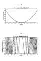
- FIG. 7 (a) is a graph showing changes in path difference at an antenna height of 5 m, a vehicle height of 3 m, and a frequency of 60 GHz
- FIG. 7 (b) is a change of phase components at an antenna height of 5 m, a vehicle height of 3 m, and a frequency of 60 GHz. Is a graph showing
- the reflection wave signal reflected by the vehicle reflection portion P is generated from the road surface GND Path difference 2 (D ( ⁇ (L, z)) ⁇ D ( ⁇ (0 (0) depending on the height z to the vehicle reflection portion P and the distance L from the position directly under the radar device 1 to the vehicle reflection portion P in the Y axis direction) , 3))) occurs (see Equations (7) and (8)).
- the reference of the path difference in FIG. 7A is immediately below the radar device 1.
- the delay time Td until the reflected wave signal reflected by the vehicle reflection portion P of the radar transmission signal is received by the radar device 1 is expressed by Formula (9).
- C represents the speed of light.
- a phase change of exp (j4 ⁇ D ( ⁇ (L, z)) / ⁇ ) occurs in the reflected wave signal reflected by the vehicle reflection portion P.
- L changes the range from Lmin to Lmax with 0 directly below the radar device 1 as zero.
- Lmin to Lmax correspond to the position on the Y axis of the range included in the beam width ⁇ BW .
- the vehicle height vehicle speed template generation unit 19 combines a plurality of vehicle heights zu and vehicle speeds v q [m / s] in one vehicle TK. the phase change of the corresponding reflected wave signal, and generates a template REP #p [z u, v q ] as according to equation (10).
- # p represents the ordinal number of combinations of parameter sets in total Nrep pieces become the vehicle height z u and the vehicle speed v q
- # p is from # 1 to #Nrep.
- u ⁇ q Nrep holds.
- n i is the template REP #p [z u, v q ]
- a number of samples of the phase component of is from 0 to floor [(Lmax-Lmin) / (v q ⁇ Trs)].
- floor [x] is an operator that rounds off the decimal point of x.
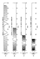
- FIG. 8 is a graph showing the change of the real component of the phase of the template for each vehicle speed at an antenna height of 5 m, the same vehicle height of 3 m, and a frequency of 60 GHz
- FIG. 8 (a) shows a case where the vehicle speed is 30 km / h b) shows the case where the vehicle speed is 60 km / h
- FIG. 8 (c) shows the case where the vehicle speed is 90 km / h
- FIG. 8 (d) shows the case where the vehicle speed is 120 km / h.
- the waveform extends in the time axis direction according to the vehicle speed.
- the vehicle height vehicle speed template generation unit 19 quantizes the phase change of the reflected wave signal according to the combination of the plurality of vehicle heights zu and the vehicle speed v q by a predetermined number of bits (for example, 1 bit or 2 bits) You may generate a template. When quantizing with one bit, the template can be expressed using two values, and when quantizing with two bits, the template can be expressed using four values. Therefore, the storage capacity of the vehicle height vehicle speed template generation unit 19 can be reduced, and the circuit scale of each of the vehicle height vehicle speed template correlation operation units # 1 to #Nrep can be reduced.
- the vehicle height vehicle speed template is generated using the height of the vehicle traveling in the vehicle travel lane as one parameter in this embodiment, the vehicle height z passes through the area detected as the radar device 1 instead of the vehicle height z.
- a template may be generated using parameters (positional parameters) that represent positional relationships with the vehicle TK.
- the vehicle height vehicle speed template correlation operation unit #p has a template length Length (REP #p ) representing the number of samples of the p-th template REP #p [z u , v q ] (n i ) (see equation (11))
- the vehicle height vehicle speed template correlation operation unit #p outputs the correlation value HV_CI (k, p, m) as the result of the correlation operation to the output selection unit 20.
- Output selecting unit 20 sets a predetermined threshold TH_Level based on each correlation value HV_CI (k, p, m) from a total of N rep vehicle height vehicle speed template correlation operation units #p (p is a natural number from 1 to Nrep). It is determined whether there is a correlation value HV_CI (k, p, m) that exceeds.
- the output selection unit 20 determines that there is a correlation value HV_CI (k, p, m) exceeding a predetermined threshold TH_Level, that is, when the equation (13) is satisfied, the vehicle TK is a beam of the radar device 1 Assuming that the vehicle travels within the width ⁇ BW , the vehicle TK is counted as the number of vehicle passages for the vehicle flow rate.
- p sel represents the ordinal number of the template for which equation (13) holds.
- Output selection unit 20 the template REP #psel [z u, v q ] a (n i) height z u and the vehicle speed v q corresponding to is selected as the estimated value of the vehicle height and speed of the vehicle TK, further, Determine the car type.
- the output selection unit 20 determines whether the vehicle is a large vehicle or a small vehicle based on the vehicle height, for example, as the vehicle type determination.
- the output selection unit 20 outputs the estimated values of the vehicle height and the vehicle speed and the vehicle type determination result to the detection result output unit 21.
- output selection unit 20 uses the maximum value among the plurality of correlation values HV_CI (k, p sel , m). The estimated value of the vehicle height and the vehicle speed of the vehicle TK may be selected.
- the output selection unit 20 may select the estimated value of the vehicle height and the vehicle speed of the vehicle TK by performing interpolation processing using each correlation value of the plurality of vehicle height vehicle speed template correlation operation units satisfying the equation (13) .
- the radar device 1 can improve the estimation accuracy of the vehicle height and the vehicle speed of the vehicle TK without increasing the number of templates, and can reduce the circuit scale.
- the detection result output unit 21 outputs the output information from the output selection unit 20 (estimated result of the vehicle type of the vehicle TK, estimated value of vehicle height and vehicle speed) to a predetermined interface in a traffic system (not shown) for monitoring road traffic volume. Send over the network.
- the radar apparatus 1 is able to reflect the vehicle TK according to the shape of the vehicle TK by correlation calculation between the template of the phase change in the reflected wave signal according to the vehicle height and vehicle speed of the vehicle TK and the reflected wave signal. Even when the reception level of the reflected wave signal from part P is small, the estimation accuracy of the vehicle height and the vehicle speed can be improved. Furthermore, since the radar device 1 adds the correlation value between the reflected wave signal and the radar transmission signal a predetermined number of times, the SNR of the reflected wave signal can be improved, and the estimation accuracy of the vehicle height and the vehicle speed can be further improved.
- the radar device 1 is installed at a height H from the ground, and the phase change amount of the reflected wave signal caused by the fluctuation amount of the Doppler frequency is small in the range of about the beam width ⁇ BW close to immediately below the radar device 1 . Therefore, the radar device 1 can set the A / D conversion units 15 and 16 to a low sampling rate, and can reduce the circuit scale.
- Vehicle height vehicle speed template generation unit 19 is a real component or an imaginary component of phase change of the reflected wave signal according to a combination of a plurality of vehicle height zu and vehicle speed v q [m / s] in one vehicle TK.
- the template may be generated in accordance with equation (14) using the above, and the same applies to the following embodiments.
- Re [x] is an operator that gives real values of complex number x.
- the vehicle height vehicle speed template correlation operation unit #p has a template length Length (REP #p ) representing the number of samples of the p-th template REP #p [z u , v q ] (n i ) (see equation (14))
- Length (REP #p ) pieces of CI (k, m) of the adding unit 18 obtained for each discrete time k the timing of the discrete time k is aligned according to the equation (12), and the correlation operation is performed.
- the processes after the output selection unit 20 are the same, and thus the description thereof is omitted.
- Vehicle height vehicle speed template generation unit 19 uses the imaginary number component of the phase change of the reflected wave signal according to the combination of a plurality of vehicle height z u and vehicle speed v q [m / s] in one vehicle TK.
- the template may be generated according to Equation (15), and the same applies to the following embodiments.
- Im [x] is an operator that gives a real value of complex number x.
- the vehicle height vehicle speed template correlation operation unit #p has a template length Length (REP #p ) representing the number of samples of the p-th template REP #p [z u , v q ] (n i ) (see equation (15))
- Length (REP #p ) pieces of CI (k, m) of the adding unit 18 obtained for each discrete time k the timing of the discrete time k is aligned according to the equation (12), and the correlation operation is performed.
- the processes after the output selection unit 20 are the same, and thus the description thereof is omitted.
- the radar device 1 generates the radar transmission signal using a code sequence of a predetermined code length Lp.
- the correlation operation unit 17 calculates the correlation value in the Mth transmission period Tr according to equation (3).
- each of the vehicle height and vehicle speed template correlation operation units performs thinning processing or down sampling processing on the template and the output of the addition unit 18 so that the template lengths used by the respective vehicle height speed template correlation operation units become equivalent. Correlation calculation may be performed later.
- each vehicle height vehicle speed template correlation operation unit performs the correlation operation in the time domain using the template length according to the vehicle speed vq , but is not limited to this, for example, high speed
- the same effect can be obtained by converting to the frequency domain using Fourier transform processing and performing correlation calculation in the frequency domain.
- the vehicle height vehicle speed template correlation operation unit #p is the p-th template REP # p [z u , v q ] (n i ) and the Length (REP # p of the addition unit 18 obtained for each discrete time k
- the FFT operation of FFT size N_FFT (#p) to be converted to the frequency domain is performed using each CI (k, m), and the product operation for each frequency element obtained is obtained using equation (16) Do.
- FFT size N_FFT (#p) as a size greater than the template length Length (REP #p), data exceeding the template length Length (REP #p) is zero-padding.
- the FFT size is preferably a power of two (power of two).
- IFFT represents the inverse Fourier transform of FFT size N_FFT (#p).
- the correlation operation using the frequency domain can reduce the circuit scale as compared with the correlation operation in the time domain.
- the template REP #p [z u, v q ] (n it) was previously carried out FFT calculation result is converted into the frequency domain, may be stored in the vehicle height speed template generating unit 19.
- the circuit scale can be reduced because the FFT operation for converting the template to the frequency domain is unnecessary.
- the vehicle height / vehicle speed template correlation operation unit #p which performs correlation operation at the discrete time k, outputs the correlation value HV_CI (k, p, m) as a result of the correlation operation to the output selection unit 20.
- FIG. 9 is a block diagram showing an internal configuration of a vehicle height vehicle speed template correlation operation unit #p in a modification of the first embodiment.
- Vehicle height speed template correlation calculating unit #p is configured to include a vehicle speed v q downsampling unit 31p and the vehicle speed v template correlation calculation unit 32p for q.
- the downsampling unit 31 p for the vehicle speed v q performs thinning processing or downsampling processing on the output CI (k, m) from the adding unit 18 at an interval of predetermined ⁇ m (v q ).
- ⁇ m (v q ) is expressed by equation (17).
- v max is the assumed maximum speed of the vehicle TK.
- the downsampling unit 31p for the vehicle speed v q outputs the correlation value after the thinning process or the downsampling process to the template correlation calculating unit 32p for the vehicle speed v q .
- the template correlation operation unit 32p for the vehicle speed v q is obtained for each discrete time k and a template length Length (REP #p ) representing the number of samples of the p-th template REP #p [z u , v q ] (n i ).
- the template correlation calculating unit 32 p for the vehicle speed v q outputs the correlation value HV_CI (k, p, m) as a result of the correlation calculation to the output selecting unit 20.
- the radar device 1 can reduce the amount of calculation of the vehicle height and speed template correlation calculation unit and the amount of buffer necessary for the calculation, and suppress deterioration of the estimation accuracy of the vehicle height and vehicle speed of the vehicle TK.
- the circuit scale can be reduced.
- FIG. 10 (a) is a schematic view showing the arrangement of the radar device 1A of the second embodiment on the YZ plane
- FIG. 10 (b) is the arrangement of the radar device 1A of the second embodiment on the XZ plane. It is a schematic diagram shown.
- the origin and the respective axes (X, Y and Z axes) are the same as in FIGS.
- a vehicle TK having a vehicle height z travels in the + Y-axis direction at a vehicle speed v.
- the angle is 90 ° (see FIG. 10A).
- the range of ⁇ included in the beam width ⁇ BW in the direction of the vehicle travel lane of the radar device 1A is represented by Expression (20). Equation (20) may also hold in the radar device 1 according to the first embodiment.
- the measurement range bin is the distance from the radar device 1A corresponding to the discrete sample value x (k, M) at the discrete time k.
- the measurement range bin R k (z) is expressed by equation (21).
- the discrete time k (z) (hereinafter also simply referred to as “k”) is expressed by equation (22).
- the radar device 1A performs correlation calculation of the output of the adding unit 18 using the template of the vehicle height z u satisfying the equation (24).
- FIG. 11 is a block diagram showing the internal configuration of the radar device 1A of the second embodiment in detail.
- the radar device 1A includes a reference signal oscillator Lo, a radar transmitter Tx, and a radar receiver RxA.
- the radar reception unit RxA has a reception RF unit 10 and a signal processing unit 11A to which the reception antenna Rx-ant is connected.
- the signal processing unit 11A includes A / D conversion units 15 and 16, a correlation operation unit 17, an addition unit 18, a distance selection output unit 35, a vehicle height vehicle speed template generation unit 19A, and a total of Npk vehicle height vehicle speed template correlation operation units # s (s is a natural number from 1 to N pk, s ⁇ p), an output selection unit 20A, and a detection result output unit 21 are included.
- Vehicle height speed template generating section 19A the phase change of the reflected wave signal corresponding to the combination of the vehicle speed v q of the vehicle height z u (k) and a predetermined vehicle speed detection range satisfying the formula (24), the template REP #s (K) It generates according to Formula (25) as [ zu (k) , vq ] ( ni ).
- the vehicle height vehicle speed template generation unit 19A satisfies the equation (24), and each path D (- ⁇ BW / 2 + ⁇ / 2- ⁇ ), D ( ⁇ BW / 2 + ⁇ ) in the range of ⁇ of the equation (20)
- the template may be generated according to equation (25).
- the peak correlation value as the correlation calculation result of each vehicle height and vehicle speed template correlation calculation unit does not straddle a plurality of measurement range bins, so the number of templates used for the correlation calculation is narrowed, and the processing of the signal processing unit 11A The amount is reduced.
- the vehicle height vehicle speed template correlation operation unit #s corresponds to the template REP #s (ks) [z u (k) , v q ] (n i ) according to the measurement range bin R ks at the discrete time k s and the distance selection output unit 35 output (CI (k s, m) ) and correlated calculation based on.
- the vehicle height vehicle speed template correlation operation unit #s is a template length Length (REP) representing the number of samples of the s-th template REP #s (ks) [z u (k) , v q ] (n i ).
- #S (ks) (see Equation (11)) and Length (REP #s (ks) ) pieces of CIs (k s , m) of the distance selection output unit 35 obtained for each discrete time k s
- the correlation operation is performed by aligning the timings of the discrete times k s according to equation (26).
- Output selection unit 20A the total Npk number of vehicle height speed template correlation calculator # correlation values from 1 ⁇ # Npk HV_CI (k s , s (k s), m) based on, exceeds a predetermined threshold TH_Level correlation value HV_CI (k s, s (k s), m) determining whether there is.
- TH_Level a predetermined threshold
- HV_CI k s, s (k s), m
- Output selecting unit 20A estimates vehicle height z u (k) and vehicle speed v q corresponding to template REP #ssel [z u (k) , v q ] (n i ), and estimates of vehicle height and vehicle speed of vehicle TK. And select the car type.
- the output selection unit 20A determines whether the vehicle is a large vehicle or a small vehicle based on the vehicle height, for example, as the vehicle type determination.
- the output selection unit 20A outputs the estimated values of the vehicle height and the vehicle speed and the vehicle type determination result to the detection result output unit 21.
- the output selection unit 20A uses the maximum value among the plurality of correlation values HV_CI (k, s sel , m).
- the estimated value of the vehicle height and the vehicle speed of the vehicle TK may be selected.
- the output selection unit 20A may select the estimated value of the vehicle height and the vehicle speed of the vehicle TK by performing interpolation processing using each correlation value of the plurality of vehicle height vehicle speed template correlation operation units satisfying the equation (27) .
- the radar device 1A can improve the estimation accuracy of the vehicle height and the vehicle speed of the vehicle TK without increasing the number of templates, and can reduce the circuit size.
- each of the vehicle height and vehicle speed template correlation operation units correlates after thinning or down sampling the template and the output of the addition unit 18 so that the template length used by each of the vehicle height and speed vehicle template correlation operation units becomes equivalent. It may be calculated.
- FIG. 12 is a block diagram showing an internal configuration of a vehicle height vehicle speed template correlation operation unit #s in a modification of the second embodiment.
- Vehicle height vehicle speed template correlation unit # s is downsample unit 411 for vehicle speed v 1 , downsample unit 412 for vehicle speed v 2 , ..., downsample unit 41 q for vehicle speed v q , and template correlation operation unit 421 for vehicle speed v 1 , Template correlation calculating unit 422 for vehicle speed v 2 ,..., Template correlation calculating unit 42 q for vehicle speed v q .
- the downsampling unit 41q for the vehicle speed v q performs thinning processing or downsampling processing on the output CI (k, m) from the distance selection output unit 35 at an interval of predetermined ⁇ m (v q ).
- ⁇ m (v q ) is expressed by equation (17).
- v max is the assumed maximum speed of the vehicle TK.
- the downsampling unit 31p for the vehicle speed v q outputs the correlation value after the thinning process or the downsampling process to the template correlation calculating unit 42q for the vehicle speed v q .
- Vehicle speed v template correlation calculator 42q for q is, s (k s) th template REP #s (ks) [z u , v q] template length Length (REP #s (ks representing the number of samples (n i) ) And the correlation value of Length (REP #s (ks) ) pieces of distance selection output unit 35 obtained for each discrete time k are decimated or down sampled at an interval of ⁇ m (v q ) And the correlation operation is performed by aligning the timings of the discrete times k s according to equation (28).
- Vehicle speed v template correlation calculation unit 42p for q is the correlation value HV_CI as a result of the correlation calculation (k s, s (k s ), m) to the output selecting unit 20A and.
- the radar device 1A can reduce the amount of calculation of the vehicle height and speed template correlation calculation unit and the amount of buffer required for the calculation, thereby suppressing deterioration of the estimation accuracy of the vehicle height and vehicle speed of the vehicle TK
- the circuit scale can be reduced.
- a road surface reflected wave signal detection unit 50 is further provided in the radar reception unit Rx of the radar device 1 of the first embodiment (see FIG. 13).
- equation (20) holds, and when the vehicle TK travels in the + Y direction, ⁇ at which the vehicle TK is detected most quickly in the range of ⁇ included in the beam width ⁇ BW is given by equation (29) Indicated.
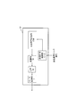
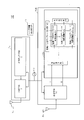
- FIG. 13 is a block diagram showing in detail the internal configuration of the radar device 1B of the third embodiment.
- the radar device 1B is configured to include a reference signal oscillator Lo, a radar transmitter Tx, and a radar receiver RxB.
- the radar receiver RxB is configured to include the reception RF unit 10 to which the reception antenna Rx-ant is connected and the signal processor 11B.
- the signal processing unit 11B includes A / D conversion units 15 and 16, a correlation operation unit 17, an addition unit 18, a vehicle height vehicle speed template generation unit 19, and a total of Nrep vehicle height vehicle speed template correlation operation units # 1 to #Nrep (p 1 to Nrep), and is configured to include a road surface reflected wave signal detection unit 50, an output selection unit 20, and a detection result output unit 21.
- the road surface reflected wave signal detection unit 50 outputs the output level of the output CI (k Droad , m) of the addition unit 18 at the discrete time k Droad at which the road surface reflected wave signal is detected from the output CI (k, m) of the addition unit 18 The point in time at which the vehicle TK enters into the area of the vehicle travel lane of about the beam width ⁇ BW of the radar device 1B is detected.
- the road surface reflected wave signal detection unit 50 determines that the vehicle TK is a radar device. It is determined that the vehicle has not entered the area of the vehicle travel lane having a beam width ⁇ BW of about 1 B.
- the road surface reflected wave signal detection unit 50 determines that the vehicle TK is a beam of the radar device 1B. It is determined that the vehicle has started to enter into the area of the vehicle travel lane having a width ⁇ BW or so. Furthermore, the road surface reflected wave signal detection unit 50 outputs the output timing of the output CI (k, m start ) of the addition unit 18 at the entry start time point to each vehicle height vehicle speed template correlation operation unit #p as a start trigger signal. . That is, m is fixed at the start position and calculated as m start .
- the road surface reflected wave signal detection unit 50 outputs the start trigger signal, if the output level of the output CI (k Droad , m) of the addition unit 18 at the discrete time k Droad exceeds the predetermined level Tlev_road again, It is determined that the entry of the vehicle TK within the area of the vehicle travel lane having a beam width ⁇ BW or so of the radar device 1B has ended. Furthermore, the road surface reflected wave signal detection unit 50 outputs the output timing of the output CI (k, m start ) of the addition unit 18 at the entry end time to each vehicle height vehicle speed template correlation operation unit #p as an end trigger signal. .
- Vehicle height speed template correlation calculating unit #p based on the start trigger signal from the road surface reflected wave signal detecting unit 50, representing the number of samples of the p-th template REP #p [z u, v q ] (n i) Using the template length Length (REP #p ) and Length (REP #p ) correlation values after CI (k, m start ) of the adding unit 18 obtained for each discrete time k, Equation (31) The correlation operation is performed by aligning the timing of the discrete time k according to. Note that m start is a fixed value.
- the output selection unit 20 detects the road surface reflected wave signal detection unit 50 among the correlation values HV_CI (k, p) from the total of N rep vehicle height vehicle speed template correlation operation units #p (p is a natural number between 1 and Nrep). The following operation is performed using the correlation value output from the output timing of the start trigger signal from the output timing of the start trigger signal to the output timing of the end trigger signal. That is, it is determined whether or not there is a correlation value HV_CI (k, p) that exceeds a predetermined threshold value TH_Level.
- the vehicle TK When it is determined that the output selection unit 20 has the correlation value HV_CI (k, p) exceeding the predetermined threshold TH_Level, that is, when the formula (13) is satisfied, the vehicle TK has the beam width ⁇ of the radar device 1B. Assuming that the vehicle has passed within BW , the vehicle TK is counted as the number of vehicle passages for the vehicle flow rate. p sel represents the ordinal number of the template for which equation (13) holds.
- the output selection unit 20 uses the maximum value among the plurality of correlation values HV_CI (k, p sel ) to obtain the vehicle.
- An estimated value of the vehicle height and the vehicle speed of TK may be selected.
- the output selection unit 20 may select the estimated value of the vehicle height and the vehicle speed of the vehicle TK by performing interpolation processing using each correlation value of the plurality of vehicle height vehicle speed template correlation operation units satisfying the equation (13) .
- the radar device 1B can improve the estimation accuracy of the vehicle height and the vehicle speed of the vehicle TK without increasing the number of templates, and can reduce the circuit size.
- Output selection unit 20 the template REP #psel [z u, v q ] a (n i) height z u and the vehicle speed v q corresponding to is selected as the estimated value of the vehicle height and speed of the vehicle TK, further, Determine the car type.
- the output selection unit 20 determines whether the vehicle is a large vehicle or a small vehicle based on the vehicle height, for example, as the vehicle type determination.
- the output selection unit 20 outputs the estimated values of the vehicle height and the vehicle speed and the vehicle type determination result to the detection result output unit 21.
- the radar device 1B can detect the start time of the correlation calculation using the template based on the presence or absence of the road surface reflection wave signal when the vehicle TK is not traveling in the vehicle travel lane, and the road surface reflection wave signal is detected.
- the period that is not detected can be taken as the correlation operation period using a template.
- the radar device 1B can simplify the circuit scale of the vehicle height / vehicle speed template correlation operation unit without using the sliding correlation operation.
- the sliding correlation operation requires FIR filters of template length, that is, registers and multipliers for the number of template sizes, but in the radar device 1B, correlation operations can be performed using the number of registers for the inverse number of template sizes and multipliers. .
- the radar device 1B can detect the start time of the correlation calculation using the template, the calculation process of the vehicle height / speed template correlation calculation unit in the period in which the vehicle TK does not exist can be unnecessary. Power can be reduced.
- Output selection unit 20 selects vehicle height z u and vehicle speed v q corresponding to template REP #psel [z u , v q ] (n i ) as estimated values of vehicle height and vehicle speed of vehicle TK instead of selecting Alternatively, vehicle type determination may be performed by the following method.
- the output selection unit 20 is a template REP #psel [z u, v q ] and the vehicle speed v q [m / s] is an estimate of the corresponding vehicle speed (n i), the output timing T start of the start trigger signal And the vehicle length L car of the vehicle that has passed within the beam width ⁇ BW of the radar device 1B based on the time interval (T end -T start ) to the output timing T end of the end trigger signal using Formula (32) Estimate and use the estimated vehicle length to determine the vehicle type.
- the output selection unit 20 determines whether the vehicle is a large vehicle or a small vehicle based on the vehicle length, for example, as the vehicle type determination.
- the output selection unit 20 outputs the estimated values of the vehicle length and the vehicle speed and the vehicle type determination result to the detection result output unit 21.
- the output selection unit 20 may further perform vehicle type determination using a vehicle height estimation result.
- vehicle type determination accuracy of the output selection unit 20 can be improved.
- FIG. 14 is a block diagram showing the internal configuration of the radar device 1C of the fourth embodiment in detail.
- the radar device 1C is configured to include a reference signal oscillator Lo, a radar transmitter Tx, and a radar receiver RxC.
- the radar reception unit RxC is configured to include the reception RF unit 10 to which the reception antenna Rx-ant is connected and the signal processing unit 11C.
- the road surface reflected wave signal detection unit 50C detects an output CI (k Droad , m) of the distance selection output unit 35 at discrete time k Droad at which the road surface reflected wave signal is detected from the output CI (k, m) of the distance selection output unit 35.
- the point in time when the vehicle TK enters into the area of the vehicle travel lane of about the beam width ⁇ BW of the radar device 1C is detected based on the output level of.
- the road surface reflected wave signal detection unit 50C detects the vehicle TK. It is determined that the vehicle has not entered into the area of the vehicle travel lane of about the beam width ⁇ BW of the radar device 1B.
- the road surface reflected wave signal detection unit 50C determines that the vehicle TK has the radar device 1C. It is determined that the vehicle has started to enter the area of the vehicle travel lane having a beam width ⁇ BW of about Furthermore, the road surface reflected wave signal detection unit 50C uses the output timing of the output CI (k, m start ) of the distance selection output unit 35 at the entry start time as the start trigger signal to each vehicle height vehicle speed template correlation operation unit #s. Output. That is, CI is calculated with m as a fixed value.
- the road surface reflected wave signal detection unit 50C outputs the start trigger signal, if the output level of the output CI (k Droad , m) of the addition unit 18 at the discrete time k Droad exceeds the predetermined level Tlev_road again, It is determined that the entry of the vehicle TK within the area of the vehicle travel lane having a beam width ⁇ BW or so of the radar device 1C has ended. Further, the road surface reflected wave signal detection unit 50C outputs the output timing of the output CI (k, m start ) of the addition unit 18 at the entry end time point to each vehicle height vehicle speed template correlation operation unit #s as an end trigger signal. .
- the vehicle height / vehicle speed template correlation operation unit #s samples the s-th template REP #s (ks) [z u , v q ] (n i ) template length length (REP #s (ks)) representing the number and discrete time k s of the distance selection output unit 35 obtained for each CI (k s, m start) after the length (REP #s (ks))
- the correlation operation is performed by aligning the timings of the discrete times k according to the equation (33) using the correlation values. Note that m start is a fixed value.
- the output selection unit 20C is a start trigger signal from the road surface reflected wave signal detection unit 50C among the correlation values HV_CI (k, p) input from the total of Nrep vehicle height and speed template correlation operation units # 1 to #Nrep. The following operation is performed using the correlation value output from the output timing of the signal to the output timing of the end trigger signal.
- the vehicle TK has a beam width ⁇ of the radar device 1. Assuming that the vehicle has passed within BW , the vehicle TK is counted as the number of vehicle passages for the vehicle flow rate. p sel represents the ordinal number of the template for which equation (13) holds.
- the output selection unit 20C uses the maximum value among the plurality of correlation values HV_CI (k, p sel ) to obtain the vehicle.
- An estimated value of the vehicle height and the vehicle speed of TK may be selected.
- the output selection unit 20 may select the estimated value of the vehicle height and the vehicle speed of the vehicle TK by performing interpolation processing using each correlation value of the plurality of vehicle height vehicle speed template correlation operation units satisfying the equation (13) .
- the radar device 1 can improve the estimation accuracy of the vehicle height and the vehicle speed of the vehicle TK without increasing the number of templates, and can reduce the circuit scale.
- Output selection unit 20C template REP #psel [z u, v q ] the vehicle height z u and the vehicle speed v q corresponding to (n i), chosen as the estimated value of the vehicle height and speed of the vehicle TK, further, Determine the car type.
- the output selection unit 20C determines whether the vehicle is a large vehicle or a small vehicle based on the vehicle height, for example, as the vehicle type determination.
- the output selection unit 20 outputs the estimated values of the vehicle height and the vehicle speed and the vehicle type determination result to the detection result output unit 21.
- the radar device 1C can detect the start time of the correlation calculation using the template based on the presence or absence of the road surface reflection wave signal when the vehicle TK is not traveling in the vehicle travel lane, and the road surface reflection wave signal is detected.
- the period that is not detected can be taken as the correlation operation period using a template.
- the radar apparatus 1C can simplify the circuit scale of the vehicle height / vehicle speed template correlation operation unit without using the sliding correlation operation.
- the sliding correlation operation requires FIR filters of template length, that is, registers and multipliers for the number of template sizes, but in the radar device 1B, correlation operations can be performed using the number of registers for the inverse number of template sizes and multipliers. .
- the radar apparatus 1C can detect the start time of the correlation calculation using the template, the calculation process of the vehicle height / speed template correlation calculation unit in the period in which the vehicle TK does not exist can be unnecessary. Power can be reduced.
- Output selection unit 20C selects vehicle height z u and vehicle speed v q corresponding to template REP #psel [z u , v q ] (n i ) as estimated values of vehicle height and vehicle speed of vehicle TK instead of selecting Alternatively, the vehicle type may be determined using the following method.
- Output selection unit 20C template REP #Psel and [z u, v q] ( n i) is an estimate of the corresponding vehicle speed to the vehicle speed v q [m / s], the output timing T start of the start trigger signal ends Based on the time interval (T end -T start ) to the output timing T end of the trigger signal, the vehicle length L car of the vehicle that has passed within the beam width ⁇ BW of the radar device 1C is estimated using Formula (32) Vehicle type is determined using the estimated vehicle length.
- the output selection unit 20C determines whether the vehicle is a large vehicle or a small vehicle based on the vehicle length, for example, as the vehicle type determination.
- the output selection unit 20 outputs the estimated values of the vehicle length and the vehicle speed and the vehicle type determination result to the detection result output unit 21.
- the output selection unit 20C may further perform vehicle type determination using a vehicle height estimation result.
- the vehicle type determination accuracy of the output selection unit 20C can be improved by using two estimated values of the vehicle height estimation and the vehicle length estimation.
- the number of vehicle travel lanes of the vehicle to be detected by the radar device is one.
- the radar apparatus 1D provides a plurality of vehicle travel lanes by providing the set of the vehicle height and speed template generation unit and the vehicle height and speed template correlation operation unit according to each embodiment described above for each vehicle travel lane of the vehicle to be detected. Vehicle can be detected.
- FIG.15 (a) is a schematic diagram which shows the arrangement condition with respect to the several vehicle travel lane on XZ plane of radar apparatus 1D of 5th Embodiment, Comprising: FIG.15 (b) is a radar apparatus of 5th Embodiment.
- 15 is a block diagram showing in detail the internal configuration of the signal processing unit 11D of FIG. In FIG. 15A, the origin and each axis (X axis, Y axis, Z axis) are the same as in FIG.
- the first vehicle travel lane X L1 is closer to the origin O than the second vehicle travel lane X L2 , and the vehicle TK1 (vehicle height z 1 ) travels on the first vehicle travel lane X L1.
- TK2 vehicle height z 2
- the perspective angle from the radar device 1D to the vehicle TK1 is ⁇ (z 1 )
- the perspective angle from the radar device 1D to the vehicle TK2 is ⁇ (z 2 ).
- a signal processing unit 11D shown in FIG. 15B includes A / D conversion units 15 and 16, a correlation operation unit 17, an addition unit 18, a distance selection output unit 35, and a vehicle height vehicle speed template generation unit 61 for the first vehicle travel lane. And a second vehicle travel lane vehicle speed template generation unit 62, a first vehicle travel lane correlation calculation unit G1, a second vehicle travel lane correlation calculation unit G2, and a detection result output unit 21.
- the first vehicle travel lane correlation calculation unit G1 includes s number of vehicle height vehicle speed template correlation calculation units # 1 to #NPk, a first vehicle travel lane road surface reflected wave signal detection unit 51, and an output selection unit 20A.
- the second vehicle travel lane correlation calculation unit G2 has the same configuration as the first vehicle travel lane correlation calculation unit G1, and in the following description, the first vehicle travel lane correlation calculation unit G1 is exemplified. the operation of detecting the vehicle TK1 traveling the first vehicle travel lane X L1 will be described.
- the first vehicle travel lane vehicle height vehicle speed template generation unit 61 Since the operations of the first vehicle travel lane vehicle height vehicle speed template generation unit 61 and the second vehicle travel lane vehicle height vehicle speed template generation unit 62 are the same, the first vehicle travel lane vehicle height vehicle speed template generation unit 61 is illustrated. The operation will be described.
- the first vehicle running lane for vehicles high speed template generating unit 61 a template in the vehicle (e.g., vehicle TK1) traveling a first vehicle running lane X L1, generated according to equation (25).
- the first vehicle running lane for the correlation calculation unit G1 uses the template from the first vehicle running lane for vehicles high speed template generating unit 61, an output CI (k s, m) from the distance selection output unit 35 and the correlation of Process the operation.
- the operation of each part of the correlation calculation unit G1 for the first vehicle travel lane is the same as the vehicle height / speed template correlation calculation unit #s, the road surface reflected wave signal detection unit 50C and the output selection unit 20C of the fourth embodiment (see FIG. 14). The description is omitted because it is similar.
- the detection result output unit 21 combines the calculation results of the first vehicle travel lane correlation calculation unit G1 and the second vehicle travel lane correlation calculation unit G2 into a traffic system (not shown) that monitors the road traffic volume. It transmits via a network of a predetermined interface.
- the radar device 1D has a small reception level of the reflected wave signal from the vehicle for each vehicle traveling in a plurality of vehicle travel lanes due to the shape of each vehicle, as in the radar device of each embodiment described above.
- the estimation accuracy of the vehicle speed and the height or the vehicle length of each vehicle can be improved, and the vehicle type can be determined.
- a radar device is a template of phase change of a reflected wave signal according to a distance relationship between a target and a radar device, and a relative velocity relationship between a target and a moving object on which the radar device is installed.
- FIG. 16 is a schematic view showing an arrangement state of a vehicle TK on which the radar device 1E of the sixth embodiment is mounted.
- the mounting position of the radar device 1E on the vehicle TK is such that, for example, the antenna directivity of the radar device 1E is any of the side surface direction of the vehicle, the side direction of the front or rear of the vehicle, diagonally forward or diagonally backward.
- the radar device 1E of this embodiment is mounted on the side of the vehicle.
- FIG. 17 is a block diagram schematically showing the internal configuration of a radar device 1E according to the sixth embodiment.
- FIG. 18 is a block diagram showing in detail the internal configuration of the radar device 1E of the sixth embodiment.
- the transmission interval Tw and the transmission period Tr of the radar transmission signal in the radar device 1E of the present embodiment are the same as the transmission period Tw and the transmission period Tr of the radar transmission signal of the radar device 1 shown in FIG.
- FIG. 16 shows a top view of a vehicle TK on which the radar device 1E is mounted.
- the main beam directions of the transmitting antenna and the receiving antenna of the radar device 1E are taken as the Y axis direction
- the direction perpendicular to the main beam direction of the transmitting antenna of the radar device 1E is taken as the X axis.
- the centers of the aperture surfaces of the transmitting antenna and the receiving antenna of the radar device 1E are set as an origin at which the X axis and the Y axis intersect.
- the radar device 1E is mounted on the side of the vehicle in FIG. 16 and the traveling direction of the vehicle TK coincides with the X axis, the traveling direction of the vehicle TK may not coincide with the X axis.
- the target to be detected is stationary, the velocity vector of the vehicle TK which radar apparatus 1E is mounted a V s, the X-axis and the angle formed between [psi, X-axis component of the velocity vector of the vehicle TK Is V s cos ⁇ , and the Y-axis component is V s sin ⁇ .
- the wedge is a parameter depending on the mounting angle at which the radar device 1E is mounted on the vehicle TK, and is a known fixed value.
- the main beam direction of the radar device 1E is the direction of the inclination angle ⁇ with respect to the side surface of the vehicle.
- the radar device 1E transmits a radar transmission signal generated by the radar transmission unit Tx from the transmission antenna Tx-ant, and receives a reflected wave signal in which the radar transmission signal is reflected by the target at the reception antenna Rx-Ant.
- the radar device 1E performs signal processing on the received reflected wave signal to obtain the distance R from the radar device 1E to the vehicle reflecting portion P (R, ⁇ ) of the target and the direction of the stationary target as viewed from the radar device 1E. Estimate the angle ⁇ .
- R represents the distance from the radar device 1E to the vehicle reflecting portion P of the target
- ⁇ represents the angle from the Y axis to the vehicle reflecting portion P of the target.
- the radar device 1 shown in FIG. 17 includes a reference signal oscillator Lo, a radar device speed detection unit 40, a radar transmission unit Tx, and a radar reception unit RxE.
- the radar transmission unit Tx includes a transmission signal generation unit 2 and a transmission RF unit 3 to which a transmission antenna Tx-ant is connected.
- the reference signal oscillator Lo is connected to the radar transmitter Tx and the radar receiver RxE, and supplies a signal from the reference signal oscillator Lo to the radar transmitter Tx and the radar receiver RxE in common, thereby enabling the radar transmitter Tx and the radar
- the processing of the receiving unit RxE is synchronized.
- the radar reception unit RxE has a reception RF unit 10 to which the reception antenna Rx-ant is connected, and a signal processing unit 11E.
- Radar transmitter The configuration and operation of the radar transmitter Tx are the same as those of the above-described embodiments, and thus the description thereof is omitted.
- the radar reception unit Rx shown in FIG. 18 has a reception RF unit 10 to which the reception antenna Rx-ant is connected, and a signal processing unit 11E.
- the reception RF unit 10 includes an amplifier 12, a frequency conversion unit 13, and a quadrature detection unit 14.
- the signal processing unit 11E includes A / D conversion units 15 and 16, a correlation operation unit 17, an addition unit 18, a distance / azimuth template generation unit 19E, N rep distance / velocity template correlation operation units #p (p is 1 to Nrep). Nrep is a predetermined natural number), an output selection unit 20, and a detection result output unit 21.
- the radar device speed detection unit 40 detects the moving speed and moving direction of the mobile unit on which the radar device 1E is mounted, and outputs the detected moving speed and moving direction to the distance / azimuth template generation unit 19E.
- the radar device speed detection unit 40 detects the moving speed by detecting the number of revolutions of the wheel per unit time.
- the radar device speed detection unit 40 detects the moving direction by converting the amount of tilt of the wheel from the amount of rotation of the steering wheel.
- the velocity vector of the moving object detected by the radar device velocity detection unit 40 is assumed to be Vs.
- the radar receiver RxE periodically calculates a signal processing section in the signal processor 11 for each transmission cycle Tr.
- reception RF unit 10 and the A / D conversion units 15 and 16 in the signal processing unit 11E are the same as those of the above-described embodiments, and thus the description thereof is omitted.
- the distance / orientation template generation unit 19E generates a distance / velocity template using a parameter indicating the positional relationship between the radar device 1E and the target based on the following properties.
- the relative velocity detected by the radar device 1E changes according to the azimuth angle ⁇ with respect to the direction from the radar device 1E to the vehicle reflecting portion P of the target with reference to the Y-axis direction shown in FIG.
- the X-axis component V s cos ⁇ and the Y-axis component V s sin ⁇ of the moving speed Vs of the vehicle TK are the detection values of the radar device speed detection unit 40, and the unknown parameters are based on the Y axis direction shown in FIG. It is an azimuth angle ⁇ with respect to the direction from the radar device 1E to the vehicle reflection part P of the target.
- the azimuth angle ⁇ with respect to the direction from the radar device 1E to the vehicle reflecting portion P of the target with respect to the Y-axis direction shown in FIG. 16 varies with time according to equation (35).
- #p represents the ordinal number of the combination of the parameter set of the distance R u and the azimuth ⁇ q for a total of N rep, and # p is from # 1 to #N rep.
- n i is the number of samples of the phase component of the template REP #p [R u , ⁇ q].
- direction (theta) q is shown by Numerical formula (37).
- the distance / orientation template generation unit 19E a plurality of distances R u and the predetermined number of bits of the phase change of the reflected wave signal corresponding to a combination of azimuth .theta.q (e.g., 1 bit or 2 bits) template quantized by It may be generated.
- the template When quantizing with one bit, the template can be expressed using two values, and when quantizing with two bits, the template can be expressed using four values. Therefore, the storage capacity of the distance / azimuth template generation unit 19E can be reduced, and the circuit scale of each of the distance / velocity template correlation calculation units # 1 to #Nrep can be reduced.
- the output selection unit 20 determines a predetermined threshold TH_Level based on each correlation value HV_CI (k, p, m) from the total of N rep distance / velocity template correlation operation units #p (p is a natural number from 1 to Nrep). It is determined whether there is a correlation value HV_CI (k, p, m) that exceeds. The output selection unit 20 determines that there is a correlation value HV_CI (k, p, m) exceeding a predetermined threshold value TH_Level, that is, when the equation (38) is established, the distance R u of the distance / velocity template The azimuth ⁇ q is output to the detection result output unit 21 as a detection value of the distance and the azimuth of the target.
- the radar device 1E when the radar device 1E is mounted on a mobile object (for example, a vehicle), the radar device 1E according to the present embodiment has the distance relationship between the stationary target and the radar device 1E, the target, and the radar device The target of the phase change template of the reflected wave signal according to the relative velocity relationship with the mobile on which 1E is mounted, and the correlation calculation between the transmission signal and the transmission signal (reception signal) reflected by the target, The distance and azimuth can be estimated.
- the present disclosure is useful as a radar device that improves the vehicle type determination accuracy of a vehicle regardless of the shape of the vehicle.
Landscapes
- Engineering & Computer Science (AREA)
- Radar, Positioning & Navigation (AREA)
- Remote Sensing (AREA)
- Physics & Mathematics (AREA)
- General Physics & Mathematics (AREA)
- Computer Networks & Wireless Communication (AREA)
- Electromagnetism (AREA)
- Radar Systems Or Details Thereof (AREA)
- Traffic Control Systems (AREA)
Abstract
Description
先ず、本開示に係るレーダ装置の各実施形態を説明する前に、各実施形態の内容に至る経緯として、車両感知器にレーダ装置を用いた従来技術を、図19~図21を参照して説明する。
図1(a)は第1の実施形態におけるレーダ装置1のYZ平面上における配置状況を示す模式図、図1(b)は第1の実施形態のレーダ装置1のXZ平面上における配置状況を示す模式図である。図2は、第1の実施形態のレーダ装置1の内部構成を簡略に示すブロック図である。図3は、第1の実施形態のレーダ装置1の内部構成を詳細に示すブロック図である。図4は、レーダ送信信号の送信区間Twと送信周期Trとの関係を示す図である。図5は、送信信号生成部2の変形例の内部構成を示すブロック図である。
なお、以下の各実施形態では、レーダ装置1の検出対象として車両TKを例示しているが、検出対象は車両TKに限定されず、例えば人でも良い。
次に、レーダ送信部Txの各部の構成を、図3を参照して詳細に説明する。
次に、レーダ受信部Rxの各部の構成を、図3を参照して説明する。
レーダ受信部Rxは、送信周期Tr毎に、信号処理部11における信号処理区間として周期的に演算する。


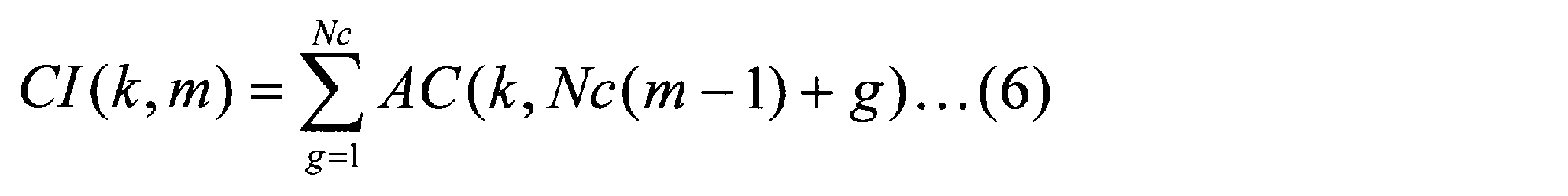

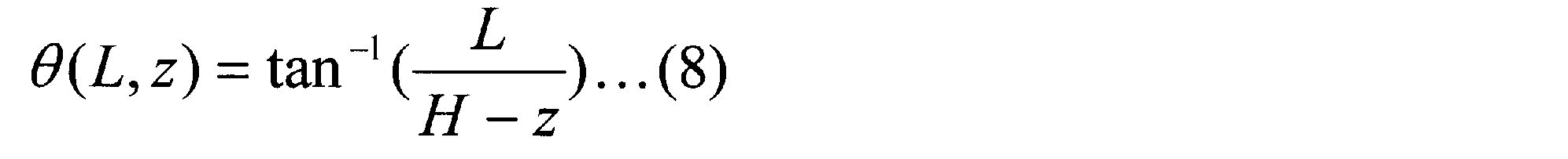


図10(a)は第2の実施形態のレーダ装置1AのYZ平面上における配置状況を示す模式図、図10(b)は第2の実施形態のレーダ装置1AのXZ平面上における配置状況を示す模式図である。図10(a)及び(b)において、原点、各軸(X軸,Y軸,Z軸)は図1(a)及び(b)と同様のため、説明を省略する。車高zを有する車両TKは、車速vにて+Y軸方向に走行する。


第3の実施形態では、第1の実施形態のレーダ装置1のレーダ受信部Rxに路面反射波信号検出部50を更に設ける(図13参照)。第3の実施形態でも数式(20)が成り立ち、車両TKが+Y方向に走行する場合にビーム幅θBWに含まれるθの範囲において最も車両TKが早く検出されるθは、数式(29)により示される。


第4の実施形態では、第2の実施形態のレーダ装置1Aのレーダ受信部RxAに路面反射波信号検出部50Cを更に設ける(図14参照)。図14は、第4の実施形態のレーダ装置1Cの内部構成を詳細に示すブロック図である。第4の実施形態では、第2又は第3の実施形態と異なる内容について説明し、第2又は第3の実施形態と同様な内容の説明は省略する。レーダ装置1Cは、基準信号発振器Lo、レーダ送信部Tx及びレーダ受信部RxCを含む構成である。
上述した各実施形態では、レーダ装置の検出対象となる車両の車両走行レーンは1つであった。第5の実施形態では、レーダ装置1Dの検出対象となる車両の車両走行レーンは複数(例えば2つ)である。レーダ装置1Dは、上述した各実施形態の車高車速テンプレート生成部と車高車速テンプレート相関演算部の組とを、検出対象となる車両の車両走行レーン毎に設けることで、複数の車両走行レーンに対して車両を検出できる。
以上、上述した各実施形態では、レーダ装置を、路面GNDから所定の高さHの位置に設置した場合を前提として説明したが、移動体(例えば車両)にレーダ装置が搭載された場合でも、本開示に係るレーダ装置は、ターゲットとレーダ装置との間の距離関係と、ターゲットとレーダ装置が設置された移動体との相対的な速度関係とに応じた反射波信号の位相変化のテンプレートと、送信信号とターゲットにより反射された送信信号(受信信号)との相関演算により、静止しているターゲットの距離及び方位角を推定できる。
レーダ送信部Txの構成及び動作は、上述した各実施形態と同様であるので、説明を省略する。
次に、レーダ受信部Rxの各部の構成を、図18を参照して説明する。
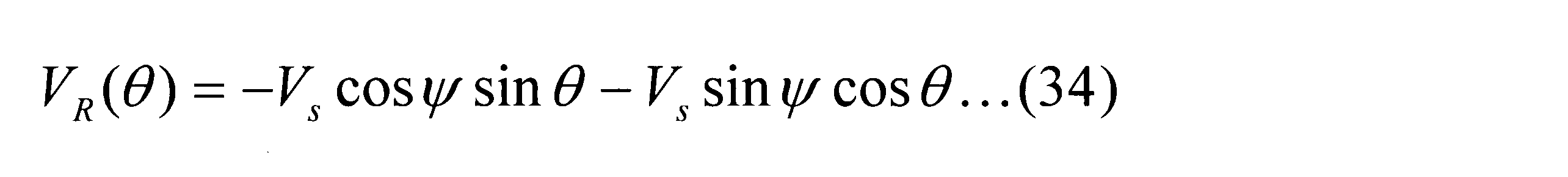
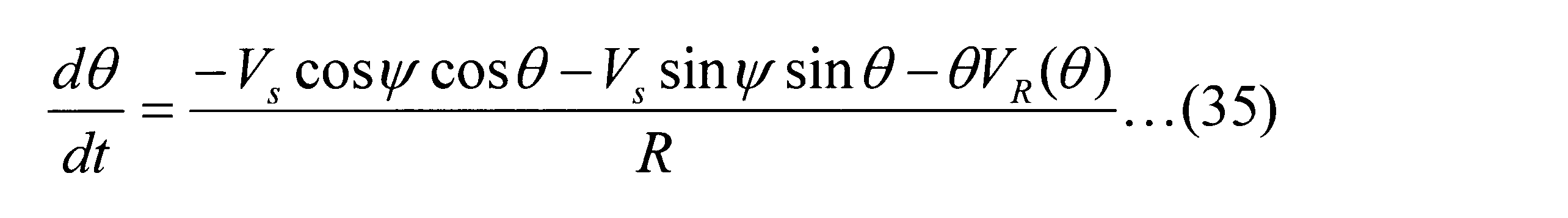
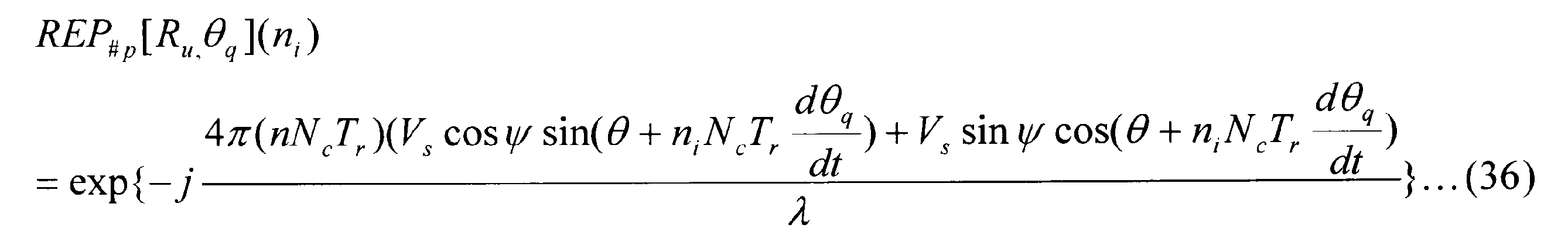


2 送信信号生成部
3 送信RF部
4 符号生成部
5 変調部
6 LPF
7 D/A変調部
8、13 周波数変換部
9、12 増幅器
10 受信RF部
11、11A、11B、11C、11D 信号処理部
14 直交変調部
15、16 A/D変換部
17 相関演算部
18 加算部
19 車高車速テンプレート生成部
20、20A 出力選択部
21 検出結果出力部
35 距離選択出力部
50 路面反射波信号検出部
#1、#p、#Nrep、#Npk 車高車速テンプレート相関演算部
Rx、RxA、RxB、RxC レーダ受信部
Tx レーダ送信部
Claims (12)
- 路面から所定の高さの位置に設置されたレーダ装置であって、
所定の俯角方向に傾けられた送信アンテナから高周波のレーダ送信信号を、前記所定の高さの位置から前記路面に向かって送信するレーダ送信部と、
前記路面を走行する車両にて反射された前記レーダ送信信号である反射波信号を用いて前記路面を走行する車両の位置パラメータ及び車速を推定するレーダ受信部と、を含み、
前記レーダ受信部は、
前記反射波信号と前記レーダ送信信号の送信符号とを基に相関演算する相関演算部と、
N個の前記車両の位置パラメータ及び車速に応じた、前記反射波信号における位相成分の変化量を、N個のテンプレートとして生成するテンプレート生成部と、
前記生成された前記N個のテンプレートのいずれかと、前記反射波信号と前記レーダ送信信号の送信符号との相関値とを基に相関演算するN個のテンプレート相関演算部と、
前記N個のテンプレート相関演算部の各出力を基に、前記生成されたN個のテンプレートのうちいずれかのテンプレートに応じた前記車両の位置パラメータ及び車速を基に車種判別を行う出力選択部と、を有するレーダ装置。 - 請求項1に記載のレーダ装置であって、
前記位置パラメータは、前記車両の高さ、又は、前記レーダ装置と前記車両との距離であるレーダ装置。 - 請求項1又は2に記載のレーダ装置であって、
前記レーダ受信部は、
前記反射波信号と前記レーダ送信信号の送信符号との相関値を、所定回数加算する加算部と、を更に有し、
各々の前記テンプレート相関演算部は、
前記加算部の出力と前記生成された前記N個のテンプレートのいずれかを基に相関演算するレーダ装置。 - 請求項1~3のうちいずれか一項に記載のレーダ装置であって、
前記出力選択部は、
前記N個のテンプレート相関演算部の各出力のうち所定の閾値を超える出力が複数ある場合に、前記所定の閾値を超える出力の最大値を推定値として選択するレーダ装置。 - 請求項1~3のうちいずれか一項に記載のレーダ装置であって、
前記出力選択部は、
前記N個のテンプレート相関演算部の各出力のうち所定の閾値を超える出力が複数ある場合に、前記所定の閾値を超える複数の出力を用いて補間処理し、前記補間処理後の出力を推定値として選択するレーダ装置。 - 請求項1~5のうちいずれか一項に記載のレーダ装置であって、
各々の前記テンプレート生成部は、
N個の前記車両の位置パラメータ及び車速に応じた、前記反射波信号における位相成分の実数成分の変化量を、N個のテンプレートとして生成するレーダ装置。 - 請求項6に記載のレーダ装置であって、
各々の前記テンプレート生成部は、
N個の前記車両の位置パラメータ及び車速に応じた、前記反射波信号における位相成分の虚数分の変化量を、N個のテンプレートとして生成するレーダ装置。 - 請求項3~7のうちいずれか一項に記載のレーダ装置であって、
各々の前記テンプレート相関演算部は、
前記加算部の出力を所定の間隔にてダウンサンプルするダウンサンプル部と、
前記ダウンサンプル後の前記加算部の出力と、前記生成された前記N個のテンプレートのいずれかを基に相関演算する相関演算部と、を含むレーダ装置。 - 請求項3に記載のレーダ装置であって、
前記所定の俯角方向は、
前記レーダ送信信号のビーム幅範囲に、前記レーダ装置と前記レーダ装置の直下を走行する前記車両との間の前記レーダ送信信号の行路が含まれる方向であって、
前記テンプレート生成部は、
各々のサンプルタイミングにおけるレンジビンに前記レーダ送信信号の行路が含まれる場合の前記車両の位置パラメータを用いて、前記車両の位置パラメータ及び車速に応じたNp(<N)個のテンプレートを生成するレーダ装置。 - 請求項9に記載のレーダ装置であって、
前記レーダ受信部は、
前記生成された前記Np個のテンプレートに応じて、前記加算部の出力を、前記Np(<N)個の前記テンプレート相関演算部に出力する距離選択出力部と、を更に有するレーダ装置。 - 請求項3に記載のレーダ装置であって、
前記レーダ受信部は、
前記加算部の出力を基に、前記路面からの路面反射波信号を検出し、前記レーダ送信信号のビーム幅範囲に対応する検出エリアに前記車両が通過開始タイミングを検出する路面反射波信号検出部と、を更に有し、
各々の前記テンプレート相関演算部は、
前記路面反射波信号の検出時刻以降における前記加算部の各出力を基に相関演算するレーダ装置。 - 請求項3に記載のレーダ装置であって、
前記レーダ受信部は、
前記加算部の出力を基に、前記路面からの路面反射波信号を検出し、前記レーダ送信信号のビーム幅範囲に対応する検出エリアに前記車両が通過開始タイミング及び通過終了タイミングを検出する路面反射波信号検出部と、を更に有し、
前記N個のテンプレート相関演算部の各出力を基に、前記生成されたN個のテンプレートのうちいずれかのテンプレートに応じた前記車両の車速を推定値として選択し、前記通過開始タイミング及び前記通過終了タイミングを基に前記車両の車長を推定する出力選択部と、を有するレーダ装置。
Priority Applications (5)
| Application Number | Priority Date | Filing Date | Title |
|---|---|---|---|
| EP19157765.9A EP3508878A1 (en) | 2012-03-19 | 2013-03-12 | Radar device |
| JP2013547772A JP6106601B2 (ja) | 2012-03-19 | 2013-03-12 | レーダ装置 |
| US14/118,087 US9322905B2 (en) | 2012-03-19 | 2013-03-12 | Radar device |
| EP13765234.3A EP2829893B1 (en) | 2012-03-19 | 2013-03-12 | Radar device |
| US15/074,713 US9547073B2 (en) | 2012-03-19 | 2016-03-18 | Radar device |
Applications Claiming Priority (2)
| Application Number | Priority Date | Filing Date | Title |
|---|---|---|---|
| JP2012-062493 | 2012-03-19 | ||
| JP2012062493 | 2012-03-19 |
Related Child Applications (2)
| Application Number | Title | Priority Date | Filing Date |
|---|---|---|---|
| US14/118,087 A-371-Of-International US9322905B2 (en) | 2012-03-19 | 2013-03-12 | Radar device |
| US15/074,713 Continuation US9547073B2 (en) | 2012-03-19 | 2016-03-18 | Radar device |
Publications (1)
| Publication Number | Publication Date |
|---|---|
| WO2013140747A1 true WO2013140747A1 (ja) | 2013-09-26 |
Family
ID=49222229
Family Applications (1)
| Application Number | Title | Priority Date | Filing Date |
|---|---|---|---|
| PCT/JP2013/001621 Ceased WO2013140747A1 (ja) | 2012-03-19 | 2013-03-12 | レーダ装置 |
Country Status (4)
| Country | Link |
|---|---|
| US (2) | US9322905B2 (ja) |
| EP (2) | EP3508878A1 (ja) |
| JP (1) | JP6106601B2 (ja) |
| WO (1) | WO2013140747A1 (ja) |
Cited By (4)
| Publication number | Priority date | Publication date | Assignee | Title |
|---|---|---|---|---|
| WO2015045224A1 (ja) * | 2013-09-27 | 2015-04-02 | パナソニック株式会社 | レーダ装置及び物体検出方法 |
| WO2018047805A1 (ja) * | 2016-09-09 | 2018-03-15 | 日本電気株式会社 | 移動音源速度推定装置、速度監視システム、移動音源速度推定方法、および移動音源速度推定用プログラムが記憶された記憶媒体 |
| KR20180080729A (ko) * | 2017-01-04 | 2018-07-13 | 주식회사 에스원 | 반사판 기반 레이더 감지기에서 차량 신호에 의한 오작동 방지 방법 및 이를 이용한 차량 신호에 의한 오작동 방지 시스템 |
| JP2022149417A (ja) * | 2021-03-25 | 2022-10-06 | 住友電気工業株式会社 | インフラ用電波レーダ、インフラ用電波レーダのデータ補正方法、補正用データ生成装置、補正用データ生成方法、及びコンピュータプログラム |
Families Citing this family (18)
| Publication number | Priority date | Publication date | Assignee | Title |
|---|---|---|---|---|
| US9470784B2 (en) * | 2011-12-02 | 2016-10-18 | Panasonic Corporation | Radar device |
| JP6037273B2 (ja) * | 2012-10-16 | 2016-12-07 | パナソニックIpマネジメント株式会社 | レーダ信号処理装置、レーダ信号処理方法、およびレーダ信号処理プログラム |
| US9513365B2 (en) * | 2013-02-21 | 2016-12-06 | Panasonic Corporation | Radar system |
| US9405003B2 (en) * | 2013-02-26 | 2016-08-02 | Panasonic Corporation | Radar apparatus |
| JP6552167B2 (ja) * | 2014-07-16 | 2019-07-31 | 株式会社デンソー | 車載レーダ装置および報知システム |
| JP6375250B2 (ja) * | 2015-03-03 | 2018-08-15 | パナソニック株式会社 | レーダ装置 |
| CN107408337B (zh) * | 2015-05-22 | 2020-06-16 | 松下知识产权经营株式会社 | 道路信息探测装置及道路信息探测方法 |
| US10177598B1 (en) * | 2015-08-26 | 2019-01-08 | Mehdi Mozafari | Energy storage system |
| JP2017173227A (ja) * | 2016-03-25 | 2017-09-28 | パナソニック株式会社 | レーダ装置及びレーダ方法 |
| JP2017227529A (ja) * | 2016-06-22 | 2017-12-28 | パナソニックIpマネジメント株式会社 | レーダ装置および追従対象決定方法 |
| CN110097763B (zh) * | 2018-01-30 | 2021-08-10 | 保定市天河电子技术有限公司 | 一种多车道车辆速度测量方法及系统 |
| CN108446023B (zh) * | 2018-03-20 | 2021-02-02 | 京东方科技集团股份有限公司 | 虚拟现实反馈装置及其定位方法、反馈方法和定位系统 |
| US10998984B2 (en) * | 2018-05-04 | 2021-05-04 | Massachuusetts Institute of Technology | Methods and apparatus for cross-medium communication |
| CN109143191B (zh) * | 2018-08-06 | 2023-01-06 | 中国航空工业集团公司雷华电子技术研究所 | 一种提高机载雷达全地形精细化检测能力的方法 |
| CN110361735B (zh) * | 2019-07-22 | 2023-04-07 | 成都纳雷科技有限公司 | 一种基于测速雷达的车辆测速方法及装置 |
| KR102653404B1 (ko) * | 2020-05-08 | 2024-04-02 | 주식회사 에이치엘클레무브 | 차량의 제어 장치 및 제어 방법 |
| JP2022122197A (ja) * | 2021-02-09 | 2022-08-22 | 株式会社アイシン | 物体検出装置及び移動体制御装置 |
| CN116859380B (zh) * | 2023-09-05 | 2023-11-21 | 长沙隼眼软件科技有限公司 | 目标航迹的测量方法、装置、电子设备及存储介质 |
Citations (5)
| Publication number | Priority date | Publication date | Assignee | Title |
|---|---|---|---|---|
| JPS52128168A (en) * | 1976-04-20 | 1977-10-27 | Matsushita Electric Ind Co Ltd | Car type discrimination device |
| JPS5825962B2 (ja) | 1976-06-11 | 1983-05-31 | 松下電器産業株式会社 | 車種判別方式 |
| JPH0552950A (ja) | 1991-08-29 | 1993-03-02 | Oki Electric Ind Co Ltd | 移動体の性状を測定する装置および移動体の速度測定方法 |
| JPH11272988A (ja) * | 1998-03-25 | 1999-10-08 | Hino Motors Ltd | 交通量調査装置 |
| JP2000056013A (ja) * | 1998-08-04 | 2000-02-25 | Meisei Electric Co Ltd | 飛翔体計測評価方法 |
Family Cites Families (12)
| Publication number | Priority date | Publication date | Assignee | Title |
|---|---|---|---|---|
| US5101200A (en) * | 1989-06-09 | 1992-03-31 | Swett Paul H | Fast lane credit card |
| DE4325672A1 (de) * | 1993-07-30 | 1995-05-04 | Siemens Ag | Verfahren zur Geschwindigkeitsmessung und Klassifizierung von Fahrzeugen mittels eines Verkehrsradargerätes |
| US7388205B1 (en) * | 1995-10-23 | 2008-06-17 | Science Applications International Corporation | System and method for target inspection using discrete photon counting and neutron detection |
| US7045787B1 (en) * | 1995-10-23 | 2006-05-16 | Science Applications International Corporation | Density detection using real time discrete photon counting for fast moving targets |
| WO1997042520A1 (en) | 1996-05-08 | 1997-11-13 | Andrews Grealie A Jr | Radar/sonar system concept for extended range-doppler coverage |
| US20060047102A1 (en) | 2004-09-02 | 2006-03-02 | Stephen Weinhold | Spheroidal polyester polymer particles |
| JP4265803B2 (ja) * | 2005-11-22 | 2009-05-20 | 三菱電機株式会社 | レーダシステム |
| TW201133412A (en) * | 2010-03-19 | 2011-10-01 | Cct Co Ltd | Method of using radar vehicle detector to determine vehicle type, speed, and radar detection zone width |
| US8736458B2 (en) * | 2010-04-29 | 2014-05-27 | Signature Research, Inc. | Weigh-in-motion scale |
| CA2839194C (en) * | 2011-06-17 | 2017-04-18 | Leddartech Inc. | System and method for traffic side detection and characterization |
| JP5825962B2 (ja) | 2011-09-30 | 2015-12-02 | 京セラ株式会社 | 窒化珪素質焼結体およびこれを用いた溶湯金属用部材ならびに耐磨耗性部材 |
| US9248832B2 (en) * | 2014-01-30 | 2016-02-02 | Mobileye Vision Technologies Ltd. | Systems and methods for detecting traffic signal details |
-
2013
- 2013-03-12 WO PCT/JP2013/001621 patent/WO2013140747A1/ja not_active Ceased
- 2013-03-12 EP EP19157765.9A patent/EP3508878A1/en not_active Withdrawn
- 2013-03-12 EP EP13765234.3A patent/EP2829893B1/en active Active
- 2013-03-12 JP JP2013547772A patent/JP6106601B2/ja not_active Expired - Fee Related
- 2013-03-12 US US14/118,087 patent/US9322905B2/en active Active
-
2016
- 2016-03-18 US US15/074,713 patent/US9547073B2/en active Active
Patent Citations (5)
| Publication number | Priority date | Publication date | Assignee | Title |
|---|---|---|---|---|
| JPS52128168A (en) * | 1976-04-20 | 1977-10-27 | Matsushita Electric Ind Co Ltd | Car type discrimination device |
| JPS5825962B2 (ja) | 1976-06-11 | 1983-05-31 | 松下電器産業株式会社 | 車種判別方式 |
| JPH0552950A (ja) | 1991-08-29 | 1993-03-02 | Oki Electric Ind Co Ltd | 移動体の性状を測定する装置および移動体の速度測定方法 |
| JPH11272988A (ja) * | 1998-03-25 | 1999-10-08 | Hino Motors Ltd | 交通量調査装置 |
| JP2000056013A (ja) * | 1998-08-04 | 2000-02-25 | Meisei Electric Co Ltd | 飛翔体計測評価方法 |
Non-Patent Citations (1)
| Title |
|---|
| RYO YUMIBA: "Study on Application of In-vehicle Millimeter-wave Radar to Vehicle Sensor", IPSJ SIG TECHNICAL REPORT, 2004-ITS-18, 28 September 2004 (2004-09-28) |
Cited By (10)
| Publication number | Priority date | Publication date | Assignee | Title |
|---|---|---|---|---|
| WO2015045224A1 (ja) * | 2013-09-27 | 2015-04-02 | パナソニック株式会社 | レーダ装置及び物体検出方法 |
| JP2015068700A (ja) * | 2013-09-27 | 2015-04-13 | パナソニック株式会社 | レーダ装置及び物体検出方法 |
| US10126417B2 (en) | 2013-09-27 | 2018-11-13 | Panasonic Corporation | Radar apparatus and object detecting method |
| WO2018047805A1 (ja) * | 2016-09-09 | 2018-03-15 | 日本電気株式会社 | 移動音源速度推定装置、速度監視システム、移動音源速度推定方法、および移動音源速度推定用プログラムが記憶された記憶媒体 |
| JPWO2018047805A1 (ja) * | 2016-09-09 | 2019-06-24 | 日本電気株式会社 | 移動音源速度推定装置、速度監視システム、移動音源速度推定方法、および移動音源速度推定用プログラム |
| US11360201B2 (en) | 2016-09-09 | 2022-06-14 | Nec Corporation | Device for estimating speed of moving sound source, speed monitoring system, method for estimating speed of moving sound source, and storage medium in which program for estimating speed of moving sound source is stored |
| KR20180080729A (ko) * | 2017-01-04 | 2018-07-13 | 주식회사 에스원 | 반사판 기반 레이더 감지기에서 차량 신호에 의한 오작동 방지 방법 및 이를 이용한 차량 신호에 의한 오작동 방지 시스템 |
| KR101927359B1 (ko) * | 2017-01-04 | 2018-12-11 | 주식회사 에스원 | 반사판 기반 레이더 감지기에서 차량 신호에 의한 오작동 방지 방법 및 이를 이용한 차량 신호에 의한 오작동 방지 시스템 |
| JP2022149417A (ja) * | 2021-03-25 | 2022-10-06 | 住友電気工業株式会社 | インフラ用電波レーダ、インフラ用電波レーダのデータ補正方法、補正用データ生成装置、補正用データ生成方法、及びコンピュータプログラム |
| JP7582008B2 (ja) | 2021-03-25 | 2024-11-13 | 住友電気工業株式会社 | インフラ用電波レーダ、インフラ用電波レーダのデータ補正方法、補正用データ生成装置、補正用データ生成方法、及びコンピュータプログラム |
Also Published As
| Publication number | Publication date |
|---|---|
| US20140085127A1 (en) | 2014-03-27 |
| US20160202348A1 (en) | 2016-07-14 |
| JP6106601B2 (ja) | 2017-04-05 |
| US9547073B2 (en) | 2017-01-17 |
| US9322905B2 (en) | 2016-04-26 |
| EP2829893B1 (en) | 2019-05-08 |
| EP2829893A1 (en) | 2015-01-28 |
| JPWO2013140747A1 (ja) | 2015-08-03 |
| EP2829893A4 (en) | 2015-04-01 |
| EP3508878A1 (en) | 2019-07-10 |
Similar Documents
| Publication | Publication Date | Title |
|---|---|---|
| WO2013140747A1 (ja) | レーダ装置 | |
| JP6304257B2 (ja) | レーダ装置、車両及び移動体速度検出方法 | |
| US11747435B2 (en) | Techniques for angle resolution in radar | |
| JP6432221B2 (ja) | レーダ装置 | |
| EP2983007B1 (en) | Radar apparatus and object sensing method | |
| JP6365251B2 (ja) | レーダ装置 | |
| EP3220162B1 (en) | Radar device and position-determination method | |
| JP5503961B2 (ja) | 観測信号処理装置 | |
| WO2013080570A1 (ja) | レーダ装置 | |
| US10416274B2 (en) | Passive radar location of objects | |
| JP2016151424A (ja) | レーダ装置 | |
| US20210173078A1 (en) | Object detection apparatus | |
| JP7224292B2 (ja) | レーダ装置およびそれを備える自動車 | |
| CN115362387B (zh) | 用于确定角度信息的方法 | |
| US20210286048A1 (en) | Radar device | |
| US10393871B2 (en) | Method for computationally simple range-doppler-angle tracking using goerzel filter | |
| US20110156945A1 (en) | Observation signal processing apparatus | |
| CN112771402B (zh) | 用于在雷达系统中进行检测的方法 |
Legal Events
| Date | Code | Title | Description |
|---|---|---|---|
| ENP | Entry into the national phase |
Ref document number: 2013547772 Country of ref document: JP Kind code of ref document: A |
|
| 121 | Ep: the epo has been informed by wipo that ep was designated in this application |
Ref document number: 13765234 Country of ref document: EP Kind code of ref document: A1 |
|
| WWE | Wipo information: entry into national phase |
Ref document number: 14118087 Country of ref document: US |
|
| WWE | Wipo information: entry into national phase |
Ref document number: 2013765234 Country of ref document: EP |
|
| NENP | Non-entry into the national phase |
Ref country code: DE |