WO2013140964A1 - タイヤ形成用の剛性中子 - Google Patents
タイヤ形成用の剛性中子 Download PDFInfo
- Publication number
- WO2013140964A1 WO2013140964A1 PCT/JP2013/055137 JP2013055137W WO2013140964A1 WO 2013140964 A1 WO2013140964 A1 WO 2013140964A1 JP 2013055137 W JP2013055137 W JP 2013055137W WO 2013140964 A1 WO2013140964 A1 WO 2013140964A1
- Authority
- WO
- WIPO (PCT)
- Prior art keywords
- tire
- core
- thermal expansion
- radial direction
- coefficient
- Prior art date
- Legal status (The legal status is an assumption and is not a legal conclusion. Google has not performed a legal analysis and makes no representation as to the accuracy of the status listed.)
- Ceased
Links
Images





Classifications
-
- B—PERFORMING OPERATIONS; TRANSPORTING
- B29—WORKING OF PLASTICS; WORKING OF SUBSTANCES IN A PLASTIC STATE IN GENERAL
- B29D—PRODUCING PARTICULAR ARTICLES FROM PLASTICS OR FROM SUBSTANCES IN A PLASTIC STATE
- B29D30/00—Producing pneumatic or solid tyres or parts thereof
- B29D30/06—Pneumatic tyres or parts thereof (e.g. produced by casting, moulding, compression moulding, injection moulding, centrifugal casting)
- B29D30/0601—Vulcanising tyres; Vulcanising presses for tyres
- B29D30/0661—Rigid cores therefor, e.g. annular or substantially toroidal cores
-
- B—PERFORMING OPERATIONS; TRANSPORTING
- B29—WORKING OF PLASTICS; WORKING OF SUBSTANCES IN A PLASTIC STATE IN GENERAL
- B29C—SHAPING OR JOINING OF PLASTICS; SHAPING OF MATERIAL IN A PLASTIC STATE, NOT OTHERWISE PROVIDED FOR; AFTER-TREATMENT OF THE SHAPED PRODUCTS, e.g. REPAIRING
- B29C33/00—Moulds or cores; Details thereof or accessories therefor
- B29C33/38—Moulds or cores; Details thereof or accessories therefor characterised by the material or the manufacturing process
-
- B—PERFORMING OPERATIONS; TRANSPORTING
- B29—WORKING OF PLASTICS; WORKING OF SUBSTANCES IN A PLASTIC STATE IN GENERAL
- B29D—PRODUCING PARTICULAR ARTICLES FROM PLASTICS OR FROM SUBSTANCES IN A PLASTIC STATE
- B29D30/00—Producing pneumatic or solid tyres or parts thereof
- B29D30/06—Pneumatic tyres or parts thereof (e.g. produced by casting, moulding, compression moulding, injection moulding, centrifugal casting)
- B29D30/0601—Vulcanising tyres; Vulcanising presses for tyres
- B29D30/0606—Vulcanising moulds not integral with vulcanising presses
-
- B—PERFORMING OPERATIONS; TRANSPORTING
- B29—WORKING OF PLASTICS; WORKING OF SUBSTANCES IN A PLASTIC STATE IN GENERAL
- B29D—PRODUCING PARTICULAR ARTICLES FROM PLASTICS OR FROM SUBSTANCES IN A PLASTIC STATE
- B29D30/00—Producing pneumatic or solid tyres or parts thereof
- B29D30/06—Pneumatic tyres or parts thereof (e.g. produced by casting, moulding, compression moulding, injection moulding, centrifugal casting)
- B29D30/08—Building tyres
- B29D30/10—Building tyres on round cores, i.e. the shape of the core is approximately identical with the shape of the completed tyre
- B29D30/12—Cores
-
- B—PERFORMING OPERATIONS; TRANSPORTING
- B29—WORKING OF PLASTICS; WORKING OF SUBSTANCES IN A PLASTIC STATE IN GENERAL
- B29C—SHAPING OR JOINING OF PLASTICS; SHAPING OF MATERIAL IN A PLASTIC STATE, NOT OTHERWISE PROVIDED FOR; AFTER-TREATMENT OF THE SHAPED PRODUCTS, e.g. REPAIRING
- B29C33/00—Moulds or cores; Details thereof or accessories therefor
- B29C33/02—Moulds or cores; Details thereof or accessories therefor with incorporated heating or cooling means
-
- B—PERFORMING OPERATIONS; TRANSPORTING
- B29—WORKING OF PLASTICS; WORKING OF SUBSTANCES IN A PLASTIC STATE IN GENERAL
- B29K—INDEXING SCHEME ASSOCIATED WITH SUBCLASSES B29B, B29C OR B29D, RELATING TO MOULDING MATERIALS OR TO MATERIALS FOR MOULDS, REINFORCEMENTS, FILLERS OR PREFORMED PARTS, e.g. INSERTS
- B29K2995/00—Properties of moulding materials, reinforcements, fillers, preformed parts or moulds
- B29K2995/0012—Properties of moulding materials, reinforcements, fillers, preformed parts or moulds having particular thermal properties
-
- B—PERFORMING OPERATIONS; TRANSPORTING
- B29—WORKING OF PLASTICS; WORKING OF SUBSTANCES IN A PLASTIC STATE IN GENERAL
- B29L—INDEXING SCHEME ASSOCIATED WITH SUBCLASS B29C, RELATING TO PARTICULAR ARTICLES
- B29L2030/00—Pneumatic or solid tyres or parts thereof
Definitions
- the present invention relates to a rigid core for forming a tire that can uniformize the thermal expansion amount of the core body during vulcanization and improve the quality of the finished tire.
- a tire forming method using a rigid core a having a core body a1 having a tire molding surface as on the outer surface (hereinafter referred to as a core method) (For example, refer to Patent Document 1).
- tire constituent members such as carcass ply, belt ply, sidewall rubber, and tread rubber are sequentially pasted on the tire molding surface as to finish the raw tire t into a finished tire (an already vulcanized product tire). It is formed in substantially the same shape as the above. Thereafter, the raw tire t is put into the vulcanizing mold b together with the rigid core a, and the raw tire t is placed between the core body a1 which is an inner mold and the vulcanizing mold b which is an outer mold. It is vulcanized.
- the core body a1 is heated from a low temperature state of 100 ° C. or less to a high temperature state close to 150 ° C. in the vulcanization mold b in order to heat vulcanize the raw tire t. Therefore, thermal expansion occurs in the core body a1, and the shape dimension of the core body a1 changes in the vulcanization mold b.
- the thermal expansion ⁇ 1 in the cross-sectional direction is a thermal expansion that expands so that the outer surface as expands outward in the meridional section of the core body a1.
- the thermal expansion ⁇ 2 in the radial direction is a thermal expansion in which the ring-shaped core body a1 expands so as to expand toward the outer side in the tire radial direction with the tire axis i as the center.
- the core body a1 has a different expansion amount d in a portion of the cross section.
- the thermal expansion ⁇ 2 in the radial direction is added to the thermal expansion ⁇ 1 in the cross-sectional direction, and the expansion amount d increases.
- the thermal expansion ⁇ 2 in the radial direction is offset from the thermal expansion ⁇ 1 in the cross-sectional direction, and the expansion amount d decreases.
- the vulcanization mold b is managed at a substantially constant temperature (for example, about 160 ° C.) throughout the vulcanization process. Therefore, the shape dimension of the cavity surface bs of the vulcanization mold b hardly changes. Therefore, due to the unevenness of the expansion amount d of the core body a1 described above, the vulcanization pressure to the green tire t (the pressing force against the cavity surface bs) is large on the tread side and small on the bead side. It is not uniform. As a result, on the bead side where the vulcanization pressure is low, there is a problem that the vulcanization is insufficient and the tire quality is deteriorated such that the air remaining in the tire is difficult to be discharged.
- a substantially constant temperature for example, about 160 ° C.
- an object of the present invention is to provide a rigid core for forming a tire that can suppress unevenness of the thermal expansion amount of the core body, make the vulcanization pressure to the raw tire uniform, and improve the tire quality. It is said.
- the invention of claim 1 of the present application includes a core body having a tire molding surface that forms a raw tire by sequentially attaching tire constituent members to an outer surface, and the tire molding surface.
- a rigid core that vulcanizes and molds the raw tire between the vulcanization mold and the core body by being put into the vulcanization mold together with the green tire formed above,
- the core body is composed of a plurality of split core pieces that are split into the tire radial direction inside and outside at a tire radial direction position P including a maximum width position P0 where the tire molding surface protrudes most outward in the tire axial direction.
- the outer divided core piece arranged on the outer side in the tire radial direction from the maximum width position P0 and the inner divided core piece arranged on the inner side in the tire radial direction from the maximum width position P0 have a coefficient of thermal expansion.
- the coefficient of thermal expansion of the inner divided core piece is larger than the coefficient of thermal expansion of the outer divided core piece.
- the core body includes a plurality of split core pieces of three or more, and each split core piece is formed of a metal material having a different coefficient of thermal expansion, and is arranged on the inner side in the tire radial direction.
- the divided core piece is characterized by having a larger coefficient of thermal expansion.
- the core body is formed by a plurality of divided core pieces that are divided inward and outward in the tire radial direction.
- the split core piece disposed on the outer side in the tire radial direction from the maximum width position P0 and the split core piece disposed on the inner side in the tire radial direction are formed of metal materials having different thermal expansion coefficients, and the tire radius The thermal expansion coefficient of the split core piece on the inner side in the direction is made larger than the thermal expansion coefficient of the split core piece on the outer side in the tire radial direction.
- the expansion amount is increased by using a metal material having a high thermal expansion coefficient. be able to.
- the expansion amount is reduced by using a metal material having a low coefficient of thermal expansion.
- the vulcanization pressure on the raw tire during vulcanization molding can be made uniform, and the tire quality is improved by suppressing insufficient vulcanization and the occurrence of air pockets inside the tire at parts where the vulcanization pressure is low be able to.
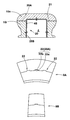
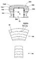
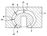
- FIG. (A) and (B) are the side view and perspective view of a core main body. It is explanatory drawing which shows an example of the connection means which connects split core pieces. It is explanatory drawing which shows the other example of a connection means. It is sectional drawing which shows the other example of a core main body. It is explanatory drawing which shows an example of the connection means which connects split core pieces. It is explanatory drawing which shows the other example of a connection means. It is sectional drawing which shows the evaluation position of the gap
- FIG. (A) to (C) are conceptual diagrams showing the structure of the core body in Table 2. FIG. It is sectional drawing explaining a core construction method. (A), (B) is a conceptual diagram explaining the problem in the conventional rigid core.
- the rigid core 1 of the present embodiment includes an annular core body 2 having a tire molding surface S on the outer surface.
- tire constituent members such as a carcass ply, a belt ply, a sidewall rubber, and a tread rubber are sequentially pasted on the tire molding surface S, thereby forming a green tire t having substantially the same shape as the finished tire.
- the green tire t is put into the vulcanization mold b together with the rigid core 1 as in the prior art, and the green tire is inserted between the core body 2 as the inner mold and the vulcanization mold b as the outer mold.
- Vulcanization molding is performed by heating and pressurizing t.
- the tire molding surface S includes the tread molding surface portion Sa that forms the inner surface of the tread portion ta of the raw tire t, the sidewall molding surface portion Sb that forms the inner surface of the sidewall portion tb, and the inner surface of the bead portion tc. It consists of a bead molding surface part Sc to be formed.
- the tire molding surface S is formed in substantially the same shape as the inner surface shape of the finished tire.
- the rigid core 1 includes the core body 2 and a cylindrical core 3 inserted into the center hole 2H of the core body 2, except for the core body 2, A conventional well-known structure can be adopted. Therefore, only the core body 2 will be described below.
- the core body 2 of the present example has a hollow shape having a lumen 4 concentric with the core body 2 in the inside thereof, and the raw tire t is heated inside the lumen 4.
- heating means such as an electric heater is arranged.
- the heating means may be configured to fill the lumen 4 with a heating fluid such as steam.
- the said core main body 2 is formed from the several core segment 9 divided
- the core segment 9 includes first and second core segments 9A and 9B that are alternately arranged in the circumferential direction.
- the dividing surfaces 9s at both ends in the circumferential direction are inclined in the direction in which the circumferential width decreases toward the inside in the radial direction.
- the dividing surfaces 9s at both ends in the circumferential direction are inclined in the direction in which the circumferential width increases inward in the radial direction.
- the core body 2 can be disassembled by sequentially moving inward in the radial direction from the second core segment 9B, and sequentially taking out from the bead hole of the finished tire after vulcanization molding.
- the core 3 prevents the core segments 9 from moving inward in the radial direction, and connects the core segments 9 together.
- the core body 2 of the present embodiment has a tire radial direction at a tire radial direction position P including a maximum width position P0 where the tire molding surface S protrudes most outward in the tire axial direction. It is formed by a plurality of divided core pieces 10 that are divided into inner and outer sides.
- the said core main body 2 is formed from two division
- the core body 2 in this example is divided into a plurality of core segments 9 in the tire circumferential direction as described above. Therefore, in the case of this example, each core segment 9 is formed by the split core pieces 10i, 10o inside and outside in the tire radial direction.
- the radially inner and outer divided core pieces 10i, 10o are connected by connecting means 20 described later, and constitute one core segment 9, respectively.
- an outer split core piece 10 o disposed on the outer side in the tire radial direction from the maximum width position P 0 and an inner split section disposed on the inner side in the tire radial direction from the maximum width position P 0.
- the child piece 10i is formed of metal materials having different coefficients of thermal expansion ⁇ . Moreover, the coefficient of thermal expansion ⁇ i of the inner divided core piece 10i is larger than the coefficient of thermal expansion ⁇ o of the outer divided core piece 10o.
- the core body 2 By configuring the core body 2 in this way, in the region where the expansion amount is small due to the thermal expansion in the radial direction (that is, the region radially inward from the maximum width position P0), Since a metal material having a large coefficient of thermal expansion ⁇ i is used for the child piece 10i, the amount of expansion can be increased. On the contrary, in the region where the expansion amount is large due to the thermal expansion in the radial direction (that is, the region outside in the radial direction from the maximum width position P0), the thermal expansion coefficient ⁇ o is small in the outer divided core piece 10o. Since a metallic material is used, the amount of expansion can be reduced.
- the core body 2 as a whole can be kept low in non-uniform expansion, and the vulcanization pressure applied to the raw tire t during vulcanization molding can be made uniform.
- the ratio ( ⁇ i / ⁇ o) of the thermal expansion coefficients ⁇ i and ⁇ o is preferably 1.07 or more, more preferably 1.34 or more.
- the connecting means 20 includes guide means 20A that is formed on the dividing surface 21 and connects the inner and outer divided core pieces 10i, 10o so as to be relatively movable in the tire axial direction.
- this guide means 20A in this example, a guide groove 22a that is recessed in one of the divided surfaces 21 and extends in the tire axial direction, and a guide rib 22b that is provided in the other divided surface 21 and is guided by the guide groove 22a.
- FIG. 3 illustrates a case where the guide grooves 22a and the guide ribs 22b are so-called dovetails and tenon tenons having a trapezoidal cross section.
- the guide means 20A can be constituted by only one set of guide pair 22.
- the guide groove 22a and the guide rib 22b may be rectangular in cross section. In such a case, it is preferable to form the plurality of guide pairs 22 toward the tire axis i in the first core segment 9A that is at least wide.
- the connecting means 20 has, for example, a U-shaped cross section extending along the surface of the lumen 4 (sometimes referred to as an inner hole surface 4S), and the inner hole surfaces of the inner and outer divided core pieces 10i, 10o.
- a holder 20B for aligning 4S is included.
- this holder 20B and each divided core piece 10i, 10o are connected by a screw metal fitting.
- the holder 20B can extend and deform in the radial direction by the thermal expansion ⁇ 2 when each of the split core pieces 10i, 10o undergoes thermal expansion ⁇ 2 in the radial direction, and thus does not hinder the effects of the present invention.
- the core body 2 can be formed by three or more divided core pieces 10 that are divided inward and outward in the tire radial direction at a plurality of tire radial direction positions P including the maximum width position P0.
- the tire radial direction position P is the maximum width position P0
- the case where the core body 2 is divided into four divided core pieces 10i1, 10i2, 10o1, 10o2 by being composed of three positions with the radial position PL is exemplified.
- each of the split core pieces 10i1, 10i2, 10o1, 10o2 is formed of a metal material having a different coefficient of thermal expansion ⁇ , and the split core piece 10 disposed on the inner side in the tire radial direction is closer to the thermal expansion coefficient ⁇ .
- the core body 2 As a result, it is possible for the core body 2 as a whole to keep the non-uniformity of the expansion amount lower, and the vulcanization pressure to the raw tire t during vulcanization molding can be made more uniform.
- the ratio ( ⁇ i2 / ⁇ o1) of the thermal expansion coefficients ⁇ i2 and ⁇ o1 is preferably 1.07 or more, and more preferably 1.34 or more.
- ⁇ o1 It may be formed by ⁇ o2
- Each of the split core pieces 10 i 1, 10 i 2, 10 o 1, 10 o 2 is also connected by the connecting means 20 to constitute one core segment 9.
- the connecting means 20 is the same as in the case of two divisions, and as shown in FIGS. 6 and 7, guide means 20A for connecting adjacent divided core pieces so as to be relatively movable in the tire axial direction, And a holder 20B for aligning the inner hole surface 4S of the child piece.
- a core body for forming a pneumatic tire having a tire size of 195 / 65R15 was prototyped based on the specifications in Table 2, and each core body was heated from a normal temperature of 20 ° C. to 150 ° C. The temperature of the core was increased by thermal expansion, and the outer shape of each core body was measured using a laser displacement meter.
- the measurement results were superimposed on the dimension after thermal expansion of the cavity surface of the vulcanization mold, and the gap amount g between the outer surface of the core body was determined and displayed as an index.
- the gap amount g is obtained by indexing the ratio of the gap amount after thermal expansion to the gap amount before thermal expansion of the core body.
- Table 2 shows the evaluation positions J1 to J4 shown in FIG. The gap amount g is indicated. The smaller the variation in the gap amount g at each of the evaluation positions J1 to J4, the more uniform the vulcanization pressure is. Evaluation position J1--Equatorial position of the tread part; Evaluation position J2--buttress part; Evaluation position J3--Maximum width position; Evaluation position J4--Clinch part;
- the vulcanization temperature conditions at the time of vulcanization molding are as follows. Vulcanizing mold --- 160 ° C Core body --- 150 ° C
- 9A to 9C conceptually show the structure of the core body, and the metal materials MA to ME used in the respective parts are shown in Table 1 above.
- the embodiment can uniformize the vulcanization pressure to the raw tire at the time of vulcanization molding, and can suppress the occurrence of air accumulation inside the tire and improve the tire quality.
Landscapes
- Engineering & Computer Science (AREA)
- Mechanical Engineering (AREA)
- Manufacturing & Machinery (AREA)
- Moulds For Moulding Plastics Or The Like (AREA)
- Heating, Cooling, Or Curing Plastics Or The Like In General (AREA)
Abstract
中子本体の熱膨張量の不均一を抑え、タイヤ品質を向上させる。中子本体は、タイヤ成形面の最大巾位置(PO)を含むタイヤ半径方向位置(P)にてタイヤ半径方向内外に分割される複数の分割中子片(10i、10o)からなる。前記最大巾位置よりもタイヤ半径方向外側に配される分割中子片(10o)と、タイヤ半径方向内側に配される分割中子片(10i)とは、熱膨張率が異なる金属材料により形成される。前記内側の分割中子片(10i)の熱膨張率は、前記外側の分割中子片(10o)の熱膨張率よりも大である。
Description
本発明は、加硫成形時における中子本体の熱膨張量を均一化し、仕上がりタイヤの品質を向上しうるタイヤ形成用の剛性中子に関する。
近年、空気入りタイヤの形成精度を高めるため、図10に示すように、外表面にタイヤ成形面asを有する中子本体a1を具える剛性中子aを用いたタイヤ形成方法(以下中子工法という場合がある。)が提案されている(例えば特許文献1参照。)。
この中子工法では、前記タイヤ成形面as上に、カーカスプライ、ベルトプライ、サイドウォールゴム、トレッドゴム等のタイヤ構成部材を順次貼り付けて生タイヤtを仕上がりタイヤ(既加硫の製品タイヤに相当する。)とほぼ同形状にて形成する。その後、この生タイヤtを前記剛性中子aごと加硫金型b内に投入し、内型である中子本体a1と外型である加硫金型bとの間で前記生タイヤtを加硫成形している。
このとき前記中子本体a1は、生タイヤtを加熱加硫するために、加硫金型b内にて100℃以下の低温状態から150℃に近い高温状態まで加熱される。そのため前記中子本体a1には熱膨張が発生し、中子本体a1の形状寸法が加硫金型b内で変化する。
ここで、前記熱膨張として、図11(A)に概念的に示すように、断面方向の熱膨張ε1と、半径方向の熱膨張ε2が発生する。断面方向の熱膨張ε1とは、中子本体a1の子午断面において、外表面asが外側に膨らむように膨張する熱膨張である。又半径方向の熱膨張ε2とは、リング状の中子本体a1が、タイヤ軸心iを中心としてタイヤ半径方向外側に向かって拡径するように膨張する熱膨張である。その結果、図11(B)に概念的に示すように、中子本体a1は、その断面の部分部分で膨張量dが相違する。特に、タイヤ成形面asの最大巾位置P0よりもトレッド側(半径方向外側)では、断面方向の熱膨張ε1に半径方向の熱膨張ε2が加算されて膨張量dが大きくなる。逆に最大巾位置P0よりもビード側(半径方向内側)では、断面方向の熱膨張ε1から半径方向の熱膨張ε2が相殺されて膨張量dが小さくなる。
これに対し、前記加硫金型bは、加硫工程全般に亘ってほぼ一定の温度(例えば160℃程度)で管理される。従って、加硫金型bのキャビティ面bsの形状寸法は、ほとんど変化しない。そのため、前述の中子本体a1の膨張量dの不均一が原因して、生タイヤtへの加硫圧力(キャビティ面bsへの押し付け力)がトレッド側では大、ビード側では小となるなど均一でなくなる。その結果、加硫圧力が低いビード側において、加硫が不十分となったり、またタイヤ内部に残留する空気が排出され難くなるなどタイヤ品質を低下させるという問題が生じる。
そこで本発明は、中子本体の熱膨張量の不均一を抑えて、生タイヤへの加硫圧力を均一化でき、タイヤ品質を向上させうるタイヤ形成用の剛性中子を提供することを目的としている。
上記課題を解決するために、本願請求項1の発明は、外表面に、タイヤ構成部材を順次貼り付けることにより生タイヤを形成するタイヤ成形面を有する中子本体を具え、かつこのタイヤ成形面上に形成された生タイヤごと加硫金型内に投入されることにより、該加硫金型と中子本体との間で前記生タイヤを加硫成形する剛性中子であって、
前記中子本体は、前記タイヤ成形面が最もタイヤ軸方向外側に突出する最大巾位置P0を含むタイヤ半径方向位置Pにてタイヤ半径方向内外に分割される複数の分割中子片からなり、
しかも前記最大巾位置P0よりもタイヤ半径方向外側に配される外側の分割中子片と、最大巾位置P0よりもタイヤ半径方向内側に配される内側の分割中子片とは、熱膨張率が異なる金属材料により形成されるとともに、
前記内側の分割中子片の熱膨張率を、前記外側の分割中子片の熱膨張率よりも大としたことを特徴としている。
前記中子本体は、前記タイヤ成形面が最もタイヤ軸方向外側に突出する最大巾位置P0を含むタイヤ半径方向位置Pにてタイヤ半径方向内外に分割される複数の分割中子片からなり、
しかも前記最大巾位置P0よりもタイヤ半径方向外側に配される外側の分割中子片と、最大巾位置P0よりもタイヤ半径方向内側に配される内側の分割中子片とは、熱膨張率が異なる金属材料により形成されるとともに、
前記内側の分割中子片の熱膨張率を、前記外側の分割中子片の熱膨張率よりも大としたことを特徴としている。
また請求項2では、前記中子本体は、3以上の複数の分割中子片からなり、かつ各分割中子片は熱膨張率が異なる金属材料により形成されるとともに、タイヤ半径方向内側に配される分割中子片ほど、熱膨張率を大としたことを特徴としている。
本発明は叙上の如く、中子本体を、タイヤ半径方向内外に分割される複数の分割中子片によって形成している。しかも最大巾位置P0よりもタイヤ半径方向外側に配される分割中子片と、タイヤ半径方向内側に配される分割中子片とを、熱膨張率が異なる金属材料によって形成するとともに、タイヤ半径方向内側の分割中子片の熱膨張率を、タイヤ半径方向外側の分割中子片の熱膨張率よりも大としている。
そのため、半径方向の熱膨張に原因して膨張量が小となる領域(即ち最大巾位置P0よりも半径方向内側の領域)では、熱膨張率の高い金属材料を用いることで膨張量を増加させることができる。逆に、半径方向の熱膨張に原因して膨張量が大となる領域(即ち最大巾位置P0よりも半径方向外側の領域)では、熱膨張率の低い金属材料を用いることで膨張量を減少させることができる。
そしてこれにより、中子本体全体として膨張量の不均一を低く抑えることが可能となる。その結果、加硫成型時の生タイヤへの加硫圧力を均一化でき、加硫圧力が低い部位に生じる加硫不足やタイヤ内部での空気溜まりの発生などを抑制し、タイヤ品質を向上させることができる。
以下、本発明の実施の形態について、詳細に説明する。
図1に示すように、本実施形態の剛性中子1は、外表面にタイヤ成形面Sを有する環状の中子本体2を具える。そして、このタイヤ成形面S上に、カーカスプライ、ベルトプライ、サイドウォールゴム、トレッドゴム等のタイヤ構成部材を順次貼り付けることにより、仕上がりタイヤとほぼ同形状の生タイヤtが形成される。又前記生タイヤtを、従来と同様、剛性中子1ごと加硫金型b内に投入し内型である中子本体2と外型である加硫金型bとの間で前記生タイヤtを加熱加圧することで加硫成形が行われる。
図1に示すように、本実施形態の剛性中子1は、外表面にタイヤ成形面Sを有する環状の中子本体2を具える。そして、このタイヤ成形面S上に、カーカスプライ、ベルトプライ、サイドウォールゴム、トレッドゴム等のタイヤ構成部材を順次貼り付けることにより、仕上がりタイヤとほぼ同形状の生タイヤtが形成される。又前記生タイヤtを、従来と同様、剛性中子1ごと加硫金型b内に投入し内型である中子本体2と外型である加硫金型bとの間で前記生タイヤtを加熱加圧することで加硫成形が行われる。
前記タイヤ成形面Sは、生タイヤtのトレッド部taの内表面を形成するトレッド成形面部Saと、サイドウォール部tbの内表面を形成するサイドウォール成形面部Sbと、ビード部tcの内表面を形成するビード成形面部Scとからなる。このタイヤ成形面Sは、仕上がりタイヤの内面形状とほぼ同形状に形成される。
又前記剛性中子1は、前記中子本体2と、この中子本体2の中心孔2Hに内挿される円筒状のコア3とを含んで構成されるが、前記中子本体2以外は、従来的な周知構造を採用できる。従って、以下に前記中子本体2のみ説明する。
本例の中子本体2は、その内部に、該中子本体2と同心な内腔部4を具えた中空状をなし、その内腔部4内には、前記生タイヤtを内側加熱する例えば電気ヒータなどの加熱手段(図示しない。)が配される。加熱手段としては、前記内腔部4内に、例えばスチームなどの加熱流体を充填する如く構成することもできる。
又前記中子本体2は、図2(A)、(B)に示すように、タイヤ周方向に分割された複数の中子セグメント9から形成される。この中子セグメント9は、周方向に交互に配される第1、第2の中子セグメント9A、9Bから構成される。第1の中子セグメント9Aは、周方向両端の分割面9sが、半径方向内方に向かって周方向巾が減じる向きに傾斜する。第2の中子セグメント9Bは、周方向両端の分割面9sが、半径方向内方に向かって周方向巾が増す向きに傾斜する。これにより、前記第2の中子セグメント9Bから順に半径方向内側に移動でき、加硫成形後、仕上がりタイヤのビード孔から順次取り出すことで、中子本体2を分解することができる。なお前記コア3は、各中子セグメント9の半径方向内側への移動を阻止し、各中子セグメント9を一体連結させる。
そして、本実施形態の中子本体2は、前記図1に示すように、前記タイヤ成形面Sが最もタイヤ軸方向外側に突出する最大巾位置P0を含むタイヤ半径方向位置Pにてタイヤ半径方向内外に分割される複数の分割中子片10によって形成される。
本例では、前記タイヤ半径方向位置Pが、前記最大巾位置P0のみからなる場合が示される。これにより前記中子本体2は、タイヤ半径方向内外の2つの分割中子片10i、10oから形成される。
本例の中子本体2は、前述の如く、タイヤ周方向の複数の中子セグメント9に分割されている。そのため本例の場合、各中子セグメント9が、タイヤ半径方向内外の分割中子片10i、10oによって形成されることとなる。なお半径方向内外の分割中子片10i、10o同士は、後述する連結手段20によって連結され、それぞれ一つの中子セグメント9を構成する。
前記分割中子片10において、前記最大巾位置P0よりもタイヤ半径方向外側に配される外側の分割中子片10oと、最大巾位置P0よりもタイヤ半径方向内側に配される内側の分割中子片10iとは、熱膨張率αが異なる金属材料により形成される。しかも、前記内側の分割中子片10iの熱膨張率αiを、前記外側の分割中子片10oの熱膨張率αoよりも大としている。
このように中子本体2を構成することにより、半径方向の熱膨張に原因して膨張量が小となる領域(即ち最大巾位置P0よりも半径方向内側の領域)では、前記内側の分割中子片10iに熱膨張率αiが大な金属材料を用いているため、膨張量を増加させることができる。逆に、半径方向の熱膨張に原因して膨張量が大となる領域(即ち最大巾位置P0よりも半径方向外側の領域)では、前記外側の分割中子片10oに熱膨張率αoが小な金属材料を用いているため、膨張量を減少させることができる。そしてこれにより、中子本体2全体として、膨張量の不均一を低く抑えることが可能となり、加硫成型時の生タイヤtへの加硫圧力を均一化することができる。この膨張量の均一化のために、前記熱膨張率αi、αoの比(αi/αo)は、1.07以上、さらには1.34以上が好ましい。
ここで、固体の線膨張率と体積膨張率との間には下記の関係がある。従って、前記熱膨張率αとして、線膨張率を採用することも、又体積膨張率を採用することもできる。なお下記の表1に、主な金属材料MA~MEにおける線膨張率が示される。
(体積膨張率)=3×(線膨張率)
(体積膨張率)=3×(線膨張率)

又前記連結手段20としては、例えば図3に示す構造のものが好適に採用しうる。具体的には、各中子セグメント9A、9Bにおいて、内の分割中子片10iと、外の分割中子片10oとは、それぞれタイヤ軸心iと同心な円筒状の分割面21によって隣接する。そして、前記連結手段20は、前記分割面21に形成され、内外の分割中子片10i、10o同士をタイヤ軸方向に相対移動可能に接続させるガイド手段20Aを含む。このガイド手段20Aとして、本例では、一方の分割面21に凹設されかつタイヤ軸方向にのびるガイド溝22aと、他方の分割面21に凸設されかつ前記ガイド溝22aに案内されるガイドリブ22bとの組み合わせ(以下ガイド対22という。)によって形成される場合が示される。前記図3には、前記ガイド溝22a及びガイドリブ22bが、断面台形状をなす所謂蟻溝及び蟻ほぞである場合が例示される。かかる場合、ガイド手段20Aとして一組のガイド対22のみで構成することができる。
なお図4に示すように、前記ガイド溝22a及びガイドリブ22bとして断面矩形状のものを採用することができる。かかる場合、少なくとも巾広となる第1の中子セグメント9Aにおいては、複数のガイド対22を、タイヤ軸心iに向けて形成するのが好ましい。
又前記連結手段20は、前記内腔部4の表面(内孔面4Sという場合がある。)に沿ってのびる例えば断面U字状をなし、内外の分割中子片10i、10oの内孔面4Sを整一させるホルダ20Bを含む。本例では、このホルダ20Bと各分割中子片10i、10oとが、ネジ金具によって連結される。前記ホルダ20Bは、各分割中子片10i、10oが半径方向に熱膨張ε2する際、その熱膨張ε2によって半径方向に延び変形しうるため、本発明の効果を妨げることがない。
次に、前記中子本体2は、最大巾位置P0を含む複数のタイヤ半径方向位置Pにてタイヤ半径方向内外に分割される3以上の複数の分割中子片10により形成することができる。
図5には、前記タイヤ半径方向位置Pが、最大巾位置P0と、この最大巾位置P0よりもタイヤ半径方向外側のタイヤ半径方向位置PUと、最大巾位置P0よりもタイヤ半径方向内側のタイヤ半径方向位置PLとの3位置からなることにより、前記中子本体2が、4つの分割中子片10i1、10i2、10o1、10o2に分割される場合が例示される。
図5には、前記タイヤ半径方向位置Pが、最大巾位置P0と、この最大巾位置P0よりもタイヤ半径方向外側のタイヤ半径方向位置PUと、最大巾位置P0よりもタイヤ半径方向内側のタイヤ半径方向位置PLとの3位置からなることにより、前記中子本体2が、4つの分割中子片10i1、10i2、10o1、10o2に分割される場合が例示される。
かかる場合、各分割中子片10i1、10i2、10o1、10o2を、それぞれ熱膨張率αが異なる金属材料により形成するとともに、タイヤ半径方向内側に配される分割中子片10ほど、熱膨張率αを大に設定することが好ましい。即ち、各分割中子片10i1、10i2、10o1、10o2の熱膨張率をαi1、αi2、αo1、αo2としたとき、αi1>αi2>αo1>αo2であるのが好ましい。
これにより、中子本体2全体として、膨張量の不均一をより低く抑えることが可能となり、加硫成型時の生タイヤtへの加硫圧力をより均一化することができる。なお膨張量の均一化のために、前記熱膨張率αi2、αo1の比(αi2/αo1)は1.07以上、さらには1.34以上が好ましい。
なお内側の分割中子片10i1と10i2とを互いに同じ金属材料(即ちαi1=αi2)にて形成しても良く、又外側の分割中子片10o1と10o2とを互いに同じ金属材料(即ちαo1=αo2)にて形成しても良い。この場合、4分割する利点がなくなる一方、4分割による加工コストや、組み立てコストの増加、及び精度低下などの不利を招くため好ましくはないが、実施可能である。
なお各分割中子片10i1、10i2、10o1、10o2も、連結手段20によって連結されることにより一つの中子セグメント9を構成する。前記連結手段20は、2分割の場合と同様であり、図6、7に示すように、隣り合う分割中子片同士をタイヤ軸方向に相対移動可能に接続させるガイド手段20Aと、各分割中子片の内孔面4Sを整一させるホルダ20Bとを含んで構成される。
以上、本発明の特に好ましい実施形態について詳述したが、本発明は図示の実施形態に限定されることなく、種々の態様に変形して実施しうる。
本発明の効果を確認するため、タイヤサイズ195/65R15の空気入りタイヤ形成用の中子本体を、表2の仕様に基づき試作するとともに、各中子本体を、20℃の常温から150℃まで昇温して熱膨張させ、それぞれの中子本体の外形形状を、レーザー変位計を用いて測定した。
そしてその測定結果を、加硫金型のキャビティ面の熱膨張後の寸法と重ね合わせ、中子本体の外表面との間の間隙量gを求めて指数化して表示した。なお前記間隙量gは、中子本体の熱膨張前における間隙量に対する、熱膨張後の間隙量の割合を指数化したものであり、表2には、図8に示す評価位置J1~J4における間隙量gが示される。各評価位置J1~J4での間隙量gのバラツキが小さいほど、加硫圧力が均一化していることを示す。
評価位置J1--トレッド部の赤道位置;
評価位置J2--バットレス部;
評価位置J3--最大巾位置;
評価位置J4--クリンチ部;
評価位置J1--トレッド部の赤道位置;
評価位置J2--バットレス部;
評価位置J3--最大巾位置;
評価位置J4--クリンチ部;
又前記中子本体を用いて空気入りタイヤを加硫成形した時のタイヤ内部での空気溜まりの発生状況を、指数化して表記した。数値が大きいほど空気溜まりの発生頻度が多いことを意味する。前記加硫成形時の加硫温度条件は、下記の通りである。
加硫金型---160℃
中子本体---150℃
加硫金型---160℃
中子本体---150℃
又図9(A)~(C)に、中子本体の構造を概念的に示し、各部位に用いる金属材料MA~MEは前記表1に示される。
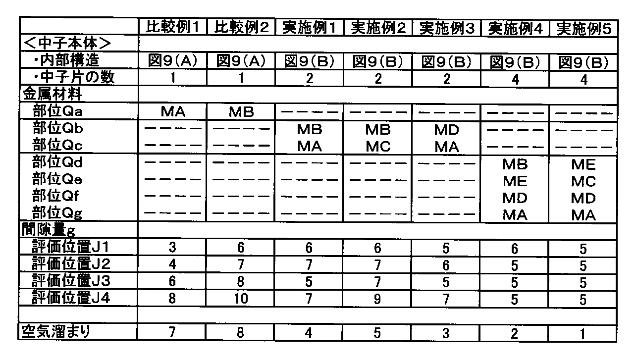
表2の如く、実施例は、加硫成型時の生タイヤへの加硫圧力を均一化でき、タイヤ内部での空気溜まりの発生を抑制しタイヤ品質を向上させうるのが確認できる。
1 剛性中子
2 中子本体
10 分割中子片
b 加硫金型
S タイヤ成形面
t 生タイヤ
2 中子本体
10 分割中子片
b 加硫金型
S タイヤ成形面
t 生タイヤ
Claims (2)
- 外表面に、タイヤ構成部材を順次貼り付けることにより生タイヤを形成するタイヤ成形面を有する中子本体を具え、かつこのタイヤ成形面上に形成された生タイヤごと加硫金型内に投入されることにより、該加硫金型と中子本体との間で前記生タイヤを加硫成形する剛性中子であって、
前記中子本体は、前記タイヤ成形面が最もタイヤ軸方向外側に突出する最大巾位置P0を含むタイヤ半径方向位置Pにてタイヤ半径方向内外に分割される複数の分割中子片からなり、
しかも前記最大巾位置P0よりもタイヤ半径方向外側に配される外側の分割中子片と、最大巾位置P0よりもタイヤ半径方向内側に配される内側の分割中子片とは、熱膨張率が異なる金属材料により形成されるとともに、
前記内側の分割中子片の熱膨張率を、前記外側の分割中子片の熱膨張率よりも大としたことを特徴とするタイヤ形成用の剛性中子。 - 前記中子本体は、3以上の複数の分割中子片からなり、かつ各分割中子片は熱膨張率が異なる金属材料により形成されるとともに、タイヤ半径方向内側に配される分割中子片ほど、熱膨張率を大としたことを特徴とする請求項1記載のタイヤ形成用の剛性中子。
Priority Applications (3)
| Application Number | Priority Date | Filing Date | Title |
|---|---|---|---|
| CN201380012346.7A CN104185541B (zh) | 2012-03-19 | 2013-02-27 | 用于形成轮胎的刚性型芯 |
| EP13764133.8A EP2818291B1 (en) | 2012-03-19 | 2013-02-27 | Rigid core for forming tire |
| US14/379,153 US9039400B2 (en) | 2012-03-19 | 2013-02-27 | Rigid core for forming tire |
Applications Claiming Priority (2)
| Application Number | Priority Date | Filing Date | Title |
|---|---|---|---|
| JP2012062357A JP5698694B2 (ja) | 2012-03-19 | 2012-03-19 | タイヤ形成用の剛性中子 |
| JP2012-062357 | 2012-03-19 |
Publications (1)
| Publication Number | Publication Date |
|---|---|
| WO2013140964A1 true WO2013140964A1 (ja) | 2013-09-26 |
Family
ID=49222427
Family Applications (1)
| Application Number | Title | Priority Date | Filing Date |
|---|---|---|---|
| PCT/JP2013/055137 Ceased WO2013140964A1 (ja) | 2012-03-19 | 2013-02-27 | タイヤ形成用の剛性中子 |
Country Status (4)
| Country | Link |
|---|---|
| US (1) | US9039400B2 (ja) |
| EP (1) | EP2818291B1 (ja) |
| JP (1) | JP5698694B2 (ja) |
| WO (1) | WO2013140964A1 (ja) |
Families Citing this family (6)
| Publication number | Priority date | Publication date | Assignee | Title |
|---|---|---|---|---|
| JP5486622B2 (ja) * | 2012-03-07 | 2014-05-07 | 住友ゴム工業株式会社 | タイヤ形成用の剛性中子 |
| JP5913266B2 (ja) | 2013-11-27 | 2016-04-27 | 住友ゴム工業株式会社 | タイヤの製造方法 |
| FR3014349B1 (fr) * | 2013-12-06 | 2016-10-21 | Michelin & Cie | Procede de decoupe de secteurs pour moules de pneumatiques |
| WO2016178970A1 (en) * | 2015-05-01 | 2016-11-10 | Compagnie Generale Des Etablissements Michelin | Method of curing a polymeric form and curing device for polymeric materials using thermal expansion |
| WO2016195633A1 (en) * | 2015-05-29 | 2016-12-08 | Compagnie Generale Des Etablissements Michelin | Curing device for polymeric materials using thermal expansion |
| US11123900B2 (en) * | 2017-09-20 | 2021-09-21 | Bell Helicopter Textron Inc. | Mold tool with anisotropic thermal properties |
Citations (4)
| Publication number | Priority date | Publication date | Assignee | Title |
|---|---|---|---|---|
| JP2003311741A (ja) * | 2002-04-23 | 2003-11-05 | Bridgestone Corp | タイヤ製造用コア |
| JP2006160236A (ja) | 2004-11-11 | 2006-06-22 | Sumitomo Rubber Ind Ltd | 空気入りタイヤ及びその製造方法 |
| JP2006264018A (ja) * | 2005-03-23 | 2006-10-05 | Yokohama Rubber Co Ltd:The | タイヤ加硫用剛性中子及び空気入りタイヤの製造方法 |
| JP2008207342A (ja) * | 2007-02-23 | 2008-09-11 | Bridgestone Corp | タイヤ加硫方法および装置 |
Family Cites Families (7)
| Publication number | Priority date | Publication date | Assignee | Title |
|---|---|---|---|---|
| US1670446A (en) * | 1928-05-22 | Method and ap-pakattjs fob making pneumatic tibes | ||
| US1170423A (en) * | 1915-07-29 | 1916-02-01 | Miller Rubber Co | Collapsible core. |
| US1213525A (en) * | 1916-07-19 | 1917-01-23 | Robert M Merriman | Collapsible core. |
| US1366750A (en) * | 1920-04-08 | 1921-01-25 | Smith Fred | Tire-casing core |
| US6113833A (en) * | 1997-07-22 | 2000-09-05 | Bridgestone Corporation | Segmented toroidal core for manufacturing pneumatic tires |
| ATE464174T1 (de) * | 1999-08-10 | 2010-04-15 | Mft Fr Pneumatiques Michelin | Steifer kern in zwei teilen, zur herstellung von luftreifen |
| JP2007050596A (ja) * | 2005-08-18 | 2007-03-01 | Bridgestone Corp | タイヤ加硫成型金型及び加硫成型方法 |
-
2012
- 2012-03-19 JP JP2012062357A patent/JP5698694B2/ja not_active Expired - Fee Related
-
2013
- 2013-02-27 US US14/379,153 patent/US9039400B2/en active Active
- 2013-02-27 WO PCT/JP2013/055137 patent/WO2013140964A1/ja not_active Ceased
- 2013-02-27 EP EP13764133.8A patent/EP2818291B1/en not_active Not-in-force
Patent Citations (4)
| Publication number | Priority date | Publication date | Assignee | Title |
|---|---|---|---|---|
| JP2003311741A (ja) * | 2002-04-23 | 2003-11-05 | Bridgestone Corp | タイヤ製造用コア |
| JP2006160236A (ja) | 2004-11-11 | 2006-06-22 | Sumitomo Rubber Ind Ltd | 空気入りタイヤ及びその製造方法 |
| JP2006264018A (ja) * | 2005-03-23 | 2006-10-05 | Yokohama Rubber Co Ltd:The | タイヤ加硫用剛性中子及び空気入りタイヤの製造方法 |
| JP2008207342A (ja) * | 2007-02-23 | 2008-09-11 | Bridgestone Corp | タイヤ加硫方法および装置 |
Non-Patent Citations (1)
| Title |
|---|
| See also references of EP2818291A4 * |
Also Published As
| Publication number | Publication date |
|---|---|
| EP2818291A4 (en) | 2015-11-18 |
| JP2013193310A (ja) | 2013-09-30 |
| EP2818291A1 (en) | 2014-12-31 |
| CN104185541A (zh) | 2014-12-03 |
| JP5698694B2 (ja) | 2015-04-08 |
| EP2818291B1 (en) | 2017-04-05 |
| US20150037443A1 (en) | 2015-02-05 |
| US9039400B2 (en) | 2015-05-26 |
Similar Documents
| Publication | Publication Date | Title |
|---|---|---|
| JP5698694B2 (ja) | タイヤ形成用の剛性中子 | |
| WO2013108537A1 (ja) | タイヤ形成用の剛性中子 | |
| CN101357510A (zh) | 轮胎成型用模具及使用了该模具的充气轮胎 | |
| CN101306580A (zh) | 用于制造充气轮胎的方法 | |
| US10695996B2 (en) | Tire vulcanization mold | |
| CN104640690B (zh) | 刚性型芯及使用该刚性型芯制造充气轮胎的方法 | |
| US9731463B2 (en) | Rigid inner mold for forming tire, and method of manufacturing tire using the same | |
| JP5486622B2 (ja) | タイヤ形成用の剛性中子 | |
| WO2018029729A1 (ja) | タイヤ加硫金型、タイヤ加硫装置及びタイヤの製造方法 | |
| US9144947B2 (en) | Rigid core for forming tire | |
| CN104185541B (zh) | 用于形成轮胎的刚性型芯 | |
| JP6454082B2 (ja) | タイヤ形成用の剛性中子、及びそれを用いたタイヤの製造方法 | |
| CN109986817B (zh) | 轮胎用模具以及轮胎的制造方法 | |
| JP4604783B2 (ja) | タイヤ加硫用剛性中子及び空気入りタイヤの製造方法 | |
| JP6641799B2 (ja) | タイヤ金型 | |
| CN102371695B (zh) | 充气轮胎的制造方法以及成型装置 | |
| JP2007015278A (ja) | タイヤ用ブラダー及びタイヤ製造方法 | |
| JP2019010779A (ja) | タイヤ加硫方法及び空気入りタイヤ | |
| JP2008119975A (ja) | タイヤの製造方法 |
Legal Events
| Date | Code | Title | Description |
|---|---|---|---|
| 121 | Ep: the epo has been informed by wipo that ep was designated in this application |
Ref document number: 13764133 Country of ref document: EP Kind code of ref document: A1 |
|
| WWE | Wipo information: entry into national phase |
Ref document number: 14379153 Country of ref document: US |
|
| NENP | Non-entry into the national phase |
Ref country code: DE |
|
| REEP | Request for entry into the european phase |
Ref document number: 2013764133 Country of ref document: EP |
|
| WWE | Wipo information: entry into national phase |
Ref document number: 2013764133 Country of ref document: EP |